

SAJ 8000m Series, 8000m-2S2R2GH, 8000m-2SR75GH, 8000m-2S1R5GH, 8000m-4T1R5GH User Manual
...
8000m Series Compact AC Drive
User Manual
Version Code :8000m-E-602000600-1705

8000m Series
- 1 -
Preface
First of all, thank you for purchasing 8000m Series Compact AC Drive!
This user manual introduces how to use 8000m series variable frequency drives
(VFDs) properly. Please read this user manual carefully before carrying out works
such as installation, commissioning, maintenance, etc.
Improper usage of VFDs would result in unpredictable accident, please deliver this
user manual to your end user. At the same time, please use VFDs until completely
understands safety instructions.
Attentions:
Illustrations in this user manual are for the convenience of understanding by user,
and it might be a bit different to the product you have purchased. As most of the
illustrations are showing the condition of VFD product with cover or safety guard
removed, please note that cover or safety guard must be installed back as required,
then operate strictly according to this user manual.
SAJ always continually improve the products, all technical parameters are subject to
change without notice. It would be possible that the old version manual is
inconformity to the new products you received. Please always use the user manual
which is included in the same package of product. If the user manual is lost or
incomplete, or there are problems or doubts, please ring the hotline of service center
of SAJ Company on 400-159-0088.

8000m Series
- 2 -
CONTENTS
Preface ................................................................................................... - 1 -
SAFETY INSTRUCTION ................................................................... - 5 -
Manual Conventions ............................................................................ - 9 -
Chapter 1 Introduction to the 8000m series VFD ........................ - 10 -
1.1 Model Description ...................................................................... - 10 -
1.2 Namplate Example ..................................................................... - 10 -
1.3 Model Table ................................................................................ - 11 -
1.4 Specifications ............................................................................. - 11 -
1.5 Dimensions and Sizes ................................................................ - 14 -
1.6 Keypad Tray Dimensions ........................................................... - 15 -
1.7 RS485 Interface .......................................................................... - 16 -
1.8 Braking Resistor Selection Table ............................................... - 16 -
Chapter 2 Installation and Wiring ................................................. - 17 -
2.1 Installation .................................................................................. - 17 -
2.2 Wiring ......................................................................................... - 22 -
Chapter 3 Keypad Operation ............................................................ - 26 -
3.1 Keypad Operation ...................................................................... - 26 -
3.2 Operation Details ....................................................................... - 27 -
Chapter 4 Function Parameter Table ............................................... - 30 -
4.1 Symbol Conventions: ................................................................. - 30 -
4.2 Function Parameter Table ........................................................... - 30 -

8000m Series
- 3 -
Chapter 5 Function Parameter Description ..................................... - 56 -
5.1 F0 Group—Basic Function ........................................................ - 56 -
5.2 F1 Group: Start and Stop Parameters ......................................... - 66 -
5.3 F2 Group: Motor Parameters ..................................................... - 70 -
5.4 F3 Group: Vector Control Parameters ........................................ - 73 -
5.5 F4 Group: V/F Control Parameters ............................................ - 76 -
5.6 F5 Group Input Terminals Parameters ....................................... - 81 -
5.7 F6 Group Output Terminals Parameters ..................................... - 92 -
5.8 F7 Group Display Interface Parameters ..................................... - 98 -
5.9 F8 Group Auxiliary Function Parameters ................................ - 101 -
5.10 F9 Group PID Control Parameters ......................................... - 108 -
5.11 FA Group Protection Parameters and Fault Records .............. - 115 -
5.12 FB Group Swing Frequency and Counting Meter Parameters- 121 -
5.13 FC Group RS485 Communication Parameters ...................... - 124 -
5.14 FD Group Multi-step Speed and Simple PLC Parameters ..... - 127 -
Chapter 6 Trouble Shooting ............................................................ - 130 -
6.1 Fault and Trouble Shooting ...................................................... - 130 -
6.2 Common Faults and Solutions ................................................. - 134 -
Chapter 7 EMC ................................................................................ - 135 -
7.1 Definition ................................................................................. - 135 -
7.2 Introduction to EMC Standard ................................................. - 135 -
7.3 EMC Guideline ........................................................................ - 135 -
Chapter 8 Communication Protocol ............................................... - 139 -
8.1 Communication Interface ......................................................... - 139 -
8.2 Communication Modes ............................................................ - 139 -

8000m Series
- 4 -
8.3 Frame Format ........................................................................... - 139 -
8.4 Protocol Function ..................................................................... - 141 -
8.5 Note .......................................................................................... - 145 -
8.6 CRC Checksum ........................................................................ - 146 -
8.7 Example .................................................................................... - 147 -
8.8 Data Address Table of Function Code ...................................... - 149 -

8000m Series
- 5 -
SAFETY INSTRUCTION
Read this user manual thoroughly before installation, operation, maintenance or
inspection of the variable frequency drive (VFD). In this manual, safety instructions
are classified as “WARNING” or “CAUTION”.
WARNING: Indicate a potentially dangerous situation which, if not avoided,
can result in death or serious injury to personnel.
CAUTION: Indicate a potentially dangerous situation which, if not avoided, can
result in minor or moderate injury and damage to equipment. It may also be used for
warning against unsafe practices.
Even items described as ( CAUTION) may result in a vital accident in some
situations. Please follow these important notes:
■ Checking Before installation
◎Do not install or operate any VFD that is damaged or has missing parts. Failing to follow
this rule can result in facility damage or severe injury.
■ Installation
◎When installing or handling the VFD, please hold the bottom of the product otherwise its case only,
thus prevent its falling and being damaged.
◎
Install the VFD on nonflammable material like metal, and keep away from flammable or
explsive object, heat source, and such environment. Otherwise it may cause a fire.
◎
Make sure that the mounting environment free of metal dust. Otherwise it may cause damage
to the VFD.
◎When VFDs is installed inside an electrical cabinet or other kind of enclosure, please install
fans or other cooling devices, and keep ventilation well enough to ensure the enclosure
temperature below 40
℃, or the VFD may be damaged due to extreme high rise of temperature.

8000m Series
- 6 -
■ Wiring
◎Ensure only qualified electrical engineering personnel for wiring work . Otherwise it
can cause an electrical shock or damage to the VFD.
◎Make sure VFD is isolated from power supply by the circuit breaker. Otherwise it may
cause electrical shock or a fire.
◎Make sure that the ground terminal is grounded correctly. Otherwise it may cause
an electrical shock.
◎Do not touch the main circuit terminals, and keep the wiring of VFD main terminals
from contacting to the enclosure, or it can cause electrical shock.
◎Terminals for brake resistor are (+) and PB. Do not wire to other terminals, otherwise
will cause a fire.
◎Before wiring, ensure the VFD’s rated input voltage and phases is compatible to the
input power source, or it can cause a fire or personal injury.
◎Never connect the AC power supply to output terminals U, V and W. Otherwise the
VFD will be damaged and the guarantee is voided.
◎Never carry out withstand voltage test to the VFD, for example by a megohm meter.
Otherwise it may cause damage to the VFD.
◎VFD’s main circuit wiring and control circuit wiring should be separated, or run
vertically from each other. Otherwise it may cause interference to the control signals.
◎Main circuit wiring cable leads should be crimped with cable lugs in insulated sleeve.
◎If the cable length between the VFD and the motor is greater than 50 meters, it is
recommended to use an output reactor to protect the VFD and the motor.

8000m Series
- 7 -
■ Operating
◎It is only allowed to power on the VFD after the wirng is finished and its cover is
reinstalled. It is strictly prohibit to remove the cover of VFD while power is on, otherwise
it may cause electric shock.
◎Before programming a VFD with fault auto reset or restart option after power off, the
mechanical device need to be implemented with safety measures first, otherwise it can lead
to personal injury.
◎”STOP/RESET” key may become invalid as a result of some function setting. It is
recommended to install an independent emergency circuit breaker for the VFD control
system, otherwise it may result in personal injury.
◎When the power is on, the VFD’s terminals may have electricity also even if it is in stop
mode. Do not touch U, V, W terminals and motor connection terminals. Otherwise it may
cause an electrical shock.
◎Do not use a magnetic contactor to control the start and stop of the VFD. Otherwise it
may cause the VFD to be damaged.
◎Before starting, please make sure that the motor and mechanical device can be run with
the VFD’s accelerating time setting in their safe range. Otherwise may result in device
damage.
◎Do not touch the heat sink or braking resistor. Otherwise it may cause harmful burns to
the body.
◎Never modify the parameters casually in unnecessary conditions, as the VFD’s default
parameter setting has already meet the requirements of most mechanical devices. Even if
some devices have special requirements, it is only needed to modify some necessary
parameters. Otherwise, it may cause device damage by improper parameter modification.

8000m Series
- 8 -
■ Maintenance
◎Never touch the VFD the connection terminals when power is on. Otherwise it may
cause an electrical shock.
◎Only qualified electrical engineering personnal can be authorized to do the jobs of
maintenance, checking, or parts replacement.
◎After the power supply is OFF, make sure the charge LED is OFF , the residual voltage
is not exist, or wait at least 10 minutes, before carrying out maintenance or inspection.
Otherwise it may cause damage or injury.
◎PCB has CMOS integrated circuit parts, never touch with bare hand, or static electricity
may cause damage to the PCB.
■ Other
◎Modification to the VFD without permission is strictly prohibited, otherwise can cause
severe injury. Arbitrarily modification of VFD will result in service guarantee voided.

8000m Series
- 9 -
Manual Conventions
In this manual we refer to 8000m Series Variable Frequency Drives as: drive,
inverter, VFD, 8000m, 8000m drive, AC drive or 8000m Series Compact AC Drive.

8000m Series
- 10 -
Chapter 1 Introduction to the 8000m series VFD
1.1 Model Description
1.2 Namplate Example

8000m Series
- 11 -
1.3 Model Table
1.4 Specifications
Control Characteristics
Control Mode V/F control
Starting Torque 0.5Hz 100%
Speed Control Range 1:20
Precision of Speed
Regulation
±1.0%
Overload Capacities
Model G: 60 seconds at 150% rated current; one second at 180%
rated current.
V/F Curve Options Three options: Linear, Square and Multipoint.
DC Injection Braking
Function
Braking start frequency: 0.00~Max. frequency limit;
Braking time:0.1~50.0s;
Braking current:0 ~150% of rated current(model G);
Braking start waiting time:0.0~50.0s.
Jog Operation
Jog frequency range: 0.00-max.frequency;
Accel./Decel. time of jog operation:0.1~3600s.
Accel./Decel. Time Accel./Decel. time range:0.1~3600s
Torque Boosting Manual setting:0.1~30.0%; Automatic setting:0.0%
Drive Model
Rated Output
Power kW
Rated Input
Current A
Rated Output
Current A
Motor Power
kW
Single-phase 220V±15%
8000m-2SR4GH 0.4 4.5 2.4 0.4
8000m-2SR75GH 0.75 8.2 4.5 0.75
8000m-2S1R5GH 1.5 14.2 7 1.5
8000m-2S2R2GH 2.2 23 10 2.2
Three-phase 380V±15%
8000m-4TR75GH 0.75 3.4 2.5 0.75
8000m-4T1R5GH 1.5 5 3.7 1.5
8000m-4T2R2GH 2.2 5.8 5.0 2.2

8000m Series
- 12 -
Input & Output Characteristics
Start Frequency 0.01~10Hz
Rated Input Voltage
220V/380V ± 15%
Rated Input
Frequency
50/60Hz,fluctuation range:±5%
Frequency Reference
Resolution
Analog signals: max. frequency × 0.1%; Digital setting:0.01Hz
Output Voltage 0: rated input voltage
Output Frequency
Range
0.00~600Hz
Peripheral I/O Characteristics
Digital Input
Terminals
4 inputs (programmable)
Analog Input
Terminals
AVI: 0~10V or 0/4~20mA (Jumper 10)
Relay Output 1 relay output (programmable)
Open Collector
Output
1 channel (programmable)
Analog Output FM: 0~10V; 0/4~20mA (Jumper 12)
Basic Functions
Operating Command
Channels
Three channels: keyboard, control input terminals, serial
communication interface. These channels can be switched by
several methods.
Frequency
References
7 references including panel potential meter, UP/DOWN key digital
setting, communication and PID control, etc.
Auxiliary Frequency
Reference
1 auxiliary frequency references, can be used in frequency
combination or adjustment.
Multi-step speed &
Simple PLC Function
14 steps multi-step speed control can be carried out by control input
terminals or built-in simple PLC function.
Built-in PID Function
Closed loop control of system variables such as pressure, speed or
temperature can be carried out by a built-in Proportional + Integral
+ Derivative (PID) controller.

8000m Series
- 13 -
Swing Frequency
Function
Suitable for some textile and chemical fiber machines by
programmable controlling of the triangular frequency references.
AVR Function
Automatic Voltage Regulation (AVR), automatically keep the
output voltage constant when power supply is not stable.
Stall Prevention
Stall Prevention automatically control the decelerating procedure
by monitoring the bus voltage and prevent overvoltage fault caused
by high inertia or rapid deceleration.
Communication
Function
RS485 communication with standard modbus protocol.
Automatic Energy
Saving Control
Automatic decrease output voltage while in the situation of light
load, to achieve efficient energy saving.
Fault Protection
Function
Over- current , over voltage, under- voltage, over temperature, lack
of phase, etc.
Personalized function
LED Display
16 parameters can by displayed including running frequency, DC
bus voltage, output voltage, output current, etc.
Password Setting
Four-digit non-zero password can be set and become effective after
exit the password programming mode and wait 1 minute.
Parameter Lock
Function
This function can be used to lock the parameter when running or
stop in order to avoid wrong operation.
Application Environment
Efficiency
At rated power
≥ 93% as 45kW and below;
≥ 95% as 55kW and above。
Location
Indoor away from sunlight, dust, corrosive gas, oil fog, driping
water or condensation.
Elevation 1000m or less
Ambient Temperature
-10℃ ~+40℃
Humidity 95% RH or less
Vibration < 5.9 m/s2 (0.6G)

8000m Series
- 14 -
1.5 Dimensions and Sizes
Dimensions Drawing
Single phase 220V 1.5-2.2kW and 3-phase380V 0.75kW-2.2kW
Single phase 220V 0.4-0.75kW

8000m Series
- 15 -
1.6 Keypad Tray Dimensions
Voltage
Class
Drive Model
Dimensions(mm)
Diameter of
installation
hole(mm0
W W1 H H1 D
Single
Phase
220V
8000m-2SR4GH
81.3 67.4 151.3 133 132.8
Φ5
8000m-2SR75GH
8000m-2S1R5GH
99.3 86.8 164.7 147.4 152
8000m-2S2R2GH
Three
Phase
380V
8000m-4TR75GH
8000m-4T1R5GH
8000m-4T2R2GH

8000m Series
- 16 -
1.7 RS485 Interface
Terminal Symbol
Function Specifications
S+ Positive pole of differential signal
Standard
RS485
interface
S- Negative pole of differential signal
+5V Positive pole of extension power (+5V)
GND Negative pole of extension power
1.8 Braking Resistor Selection Table
Inverter Model
Recommended Power
of Brake Resistor
Recommended
Resistance Value of
Brake Resistor
Brake Unit
8000m-2SR4GH 50W ≥150Ω
Standard
Accessory Inside
8000m-2SR75GH 80W ≥150Ω
8000m-2S1R5GH 100W ≥100Ω
8000m-2S2R2GH 100W ≥70Ω
8000m-4TR75GH 150W ≥300Ω
8000m-4T1R5GH 150W ≥220Ω
8000m-4T2R2GH 250W ≥200Ω

8000m Series
- 17 -
Chapter 2 Installation and Wiring
2.1 Installation
2.1.1 Installation Environment
◎The ambient temperature exerts great influences on the service life of the VFDs
and is not allowed to exceed the specified temperature range (-10℃ to 40℃ ).
◎A VFD is easy to generate large amount of heat during operation. Thus VFDs
should be mounted vertically with screws on the surface of incombustible objects,
with sufficient spaces nearby for heat sinking.
◎VFDs should be mounted in the place without vibration or with vibration of less
than 0.6G, especially away from those kinds or machine such as punch.
◎The inverter should be mounted in locations away from direct sunlight, high
humidity, condensate, corrosive gas, explosive gas, oil dirt, dust, and metal powder
etc.
2.1.2Installation Orientation & Clearance
Single Drive & multi drives (Side by Side) Installation

8000m Series
- 18 -
Multi Drive (up and down) Installation
When take up and down installation, air deflector should be installed between upper
and lower VFD, as illustrated below.

8000m Series
- 19 -
2.1.4 Electric Elements and Material
Peripheral Electric Elements
Connection Diagram

8000m Series
- 20 -
2.1.5 Descriptions of External Electrical Parts
Name Mounting Location Function
Circuit
Breaker
Front end of input circuit
Disconnect the power supply when the
backward equipment is over current.
Contactor
Between the circuit breaker
and inverter input side
Power ON/OFF of inverter. Do not use the
contactor as the switch of inverter. Otherwise,
it may cause damage to the inverter.
AC Reactor
at the Input
Side
Input side of inverter
1. Improve the power factor of the input side.
2. Eliminate the harmonic wave at the input
side effectively and prevent other equipment
from damage.
3. Eliminate the input current unbalance
caused by unbalance between the power
phases.
EMC Input
Filter
Input side of inverter
1. Reduce the external conduction and
radiation interference of inverter.
2. Decrease the conduction interference
flowing from the power end to the inverter and
improve the anti-interference capacity of the
inverter.
AC Reactor
at the
Output Side
Between inverter output side
and motor. Close to inverter.
The inverter output side generally has higher
harmonics. When the motor is far from
inverter, since there are many distributed
capacitors in the circuit, certain harmonics
may cause resonance in the circuit and bring
the following two impacts:
1. Degrade the motor insulation performance
and damage the motor when running for long
time.
2. Generate large leakage current and cause
frequent inverter protection.
Generally, installation of output AC reactor is
recommended when the distance between
inverter and motor exceeds 50m.
2.1.6 Table of Recommended Circuit Breaker, Contactor and Wire

8000m Series
- 21 -
Inverter Model
Circuit
Breaker
(MCCB) (A)
Recommend
ed Contactor
(A)
Conducting
Wire of Main
Circuit at the
Input Side
(mm2)
Conducting
Wire of Main
Circuit at the
Input Side
(mm2)
Conducting
Wire of
Control
Circuit
(mm2)
8000m-2SR75GB 16 10 2.5 2.5 1.0
8000m-2SR75GB 16 10 2.5 2.5 1.0
8000m-2S1R5GB 20 16 4.0 2.5 1.0
8000m-2S2R2GB 32 20 6.0 4.0 1.0
8000m-4TR75GB 10 10 2.5 2.5 1.0
8000m-4T1R5GB 16 10 2.5 2.5 1.0
8000m-4T2R2GB 16 10 2.5 2.5 1.0
2.1.7 Table of Recommended Reactor
Inverter Model
AC Reactor at the Input
Side
AC Reactor at the output
Side
Voltage
Current (A)
Inductance
(mH)
Current (A)
Inductance
(mH)
8000m-2SR75GB 2 7 2 7
220V
8000m-2SR75GB 2 7 2 7
8000m-2S1R5GB 5 3.8 5 3.8
8000m-2S2R2GB 7.5 2.5 7.5 2.5
8000m-4TR75GB 2 7 2 3
380V
8000m-4T1R5GB 5 3.8 5 1.5
8000m-4T2R2GB 7 2.5 7 1

8000m Series
- 22 -
2.2 Wiring
2.2.1 Wiring Diagram
Note:
1. ◎ refers to terminals of main circuit; ○ refers to terminals of control circuit.
2. For 220V single phase inverter, the terminals of main circuit are R and S.

8000m Series
- 23 -
2.2.2 Main Circuit Terminals
Terminals Descriptions
R, S and T
AC power inputterminals.
3-phase: R, S and T
Single phase: R and S
U, V and W AC power output terminals (For connecting motor)
(+) DC bus terminal of positive pole
PB Terminal for connecting brake resistor outside
Grounding terminal
2.2.3 Jumper Options
FM Jumper J2 Note
0-10VDC
Default
0-20mA
AVI Jumper J10 Note
0-10VDC
Default
0-20mA

8000m Series
- 24 -
2.2.4 Precautions on Main Circuit Wiring
2.2.4.1 Terminals R, S and T
The wiring at the input side of inverter has no phase sequence requirement. When
input single-phase power, use terminal R and T.
2.2.4.2 DC Bus Terminals (+) and PB of Brake Resistor
The (+) terminal of DC bus have residual voltage right after power-off.
Wait until the CHARGE indicator is OFF and make sure that the voltage is less
than 36V before wiring. Otherwise it may cause electrical shock.
The cable length of brake resistor should be less than 5m.
2.2.4.3 Terminals U, V and W
Capacitor device or surge absorber cannot be connected to inverter output side by
terminals U, V and W. Otherwise, it may cause frequent inverter protection or
damage to inverter.
If motor cable is too long, it may generate electrical resonance easily due to the
impact of distributed capacitance and thus damage the motor insulation or generate
higher leakage current to cause inverter protection. When the length of motor cable
is longer than 50m, installing AC reactor at the output side is necessary.
2.2.4.4 Grounding Terminal
The terminal should be grounded reliably. The resistance value of grounding cable
should be less than 10Ω. Otherwise, it may cause fault or damage to the inverter.
Do not share the grounding terminal with zero line of power supply.

8000m Series
- 25 -
2.2.5 Control Circuit Terminals
Symbol Terminal Name Function
M1~M4
Multi-functional digital
input terminals
Do not connect additional power source
directly.
A digital input is ON when it is connected to
GND, and will be OFF when it is opened.
Action current is 10mA.
GND Ground terminal Zero potential of +10V and +24V
MO1
Multi-functional open
collector output terminal
(Optical coupling isolating)Max. DC
48V/50mA
AVI Analog input terminal
Default: Input voltage range DC 0~10V (input
impedance:20kΩ)
Option: DC current 0-20mA (Jumper J10)
10V Analog reference voltage 10V ±5%, Max. current: 30mA
FM Analog output terminal
Default: DC voltage 0-10V
Option: DC current 4-20mA (Jumper J2)
TA/TB/ TC
Programmable Relay
Output
TA-TB: normally open;
TB-TC: normally closed;
Contact capacity:
AC 250V / 3A/ normally open
AC 250V / 3A / normally closed
+24V +24V power supply
Output current: Maxi. 200mA, usually used as
power of digital input/output terminals and
external sensor.
2.2.5 Precautions for Connecting Control Circuit Terminals
It is necessary to use shielded cable and twisted pair cable well-grounded (inverter
side). The cable should be more than 20cm away from power electricity cables and
conductors. Do not run the control cable paralleling to power electricity cables, try
vertically.

8000m Series
- 26 -
Chapter 3 Keypad Operation
3.1 Keypad Operation
3.1.1 Keypad Outline
3.1.2 Keys Description
Symbol Key Name Function Description
PRGM Program/ Exit key Enter or exit of menu, parameter modification
ENT Enter key Progressively enter menu and confirm parameter
UP
increase key
Progressively increase data or function codes.
DOWN decrease
key
Progressively decrease data or function codes.

8000m Series
- 27 -
<<
Shift key
Use it to select displayed parameters cyclically during
running or stop status. In parameter setting mode, press
this key to select the bit to be modified.
RUN/STOP
Run/Stop/Reset
key
For start, stop and reset operation, depends on control
mode setting.
3.1.3 Indicator Light Description
Indicator Light Description
Run light on: Drive running
Hz light on: Frequency Display
V light on: Voltage Display
A light on: Current Display
3.2 Operation Details
3.2.1 Parameter Setting
Three levels of menu are as following:
· Function code group (first-class)
· Function code (second-class)
· Setting parameter of function code (third-class)
Remarks:
Pressing PRGM or ENT can return to the second-class menu from the third-class
menu. The difference is: Pressing ENT will save the setting parameters into control
board, and return to the second-class menu with shifting to the next function code
automatically. While pressing PRGM will directly return to the second-class menu
without saving the parameters, and keep staying at the current function code.

8000m Series
- 28 -
For example:
Change function code F1.01 from 0.50Hz into 05.00Hz as shown in the following
flow chart:
Flow Chart of Parameter Setting
Under the third-class menu, if the parameter has no flickering bit, it means that the
function code cannot be modified. The possible reasons include:
(1) The parameter of this function code can’t be modified, such as actually detected
parameter, operation records and so on.
(2) This function code can’t be modified during running status, but can be modified
during stop status.

8000m Series
- 29 -
3.2.2 Fault Reset
When inverter malfunction occurs, it will display the relative fault information. Use
the RUN/STOP key or terminals (determined by F5 group) to reset the fault. After
fault reset, inverter is at stand-by status. If not reset when inverter is at fault status, it
will keep operation protection status and cannot run.
3.2.4 Password Setting
When F7.00 is set to be non-zero, the parameter will be the user’s password.
After exit the function code editing status, the password will be effective after
one minute. And then press the PRGM key again to try to access the function
code editing mode, the inverter panel will display “0.0.0.0”. The password
must be input correctly to access it. If it is necessary to cancel the password
function, set F7.00 to zero.
Notice: When the inverter is powered on, system will execute initialization first and
inverter panel displays “A13” with four lights on. After initialization, inverter
accesses into stand-by status.

8000m Series
- 30 -
Chapter 4 Function Parameter Table
4.1 Symbol Conventions:
“○”: The parameters can be modified both at stop and running status.
“◎”: The parameters cannot be modified at running status.
“●”: The parameters are actual-detecting record value or factory preserved settings
and cannot be modified.
4.2 Function Parameter Table
Function
Code
Function Descriptions
Minimum
Unit
Factory
Setting
Modification Type
F0 Group: Basic Parameters
F0.00
Control mode
selection
0: Reserved
1:V/F control
1 ●
F0.01
Control command
source
0:Keypad
1:Terminals
2: Communications (RS485)
0 ●
F0.02
Options for keypad
/ terminals
frequency
ascending and
descending control
0: Valid and saved when
power-off
1: Valid and not saved when
power-off
2: Invalid
3: Valid at running status.
Changed into the setting value
of F0.08 when restart after stop.
0 ○
F0.03
Settings of master
frequency source X
0: Up/down key
1: Potentiometer of panel
2: AVI terminal
1 ●

8000m Series
- 31 -
Function
Code
Function Descriptions
Minimum
Unit
Factory
Setting
Modification Type
F0.03
Settings of master
frequency source X
3: Reserved
4: Reserved
5: Reserved
6: Multi-function digital input
terminals
7: PLC
8: PID
9: Communication interface
1 ●
F0.04
Settings of
auxiliary
frequency source Y
0: AVI terminal
1: Reserved
2: Reserved
1 ●
F0.05
Setting range of
auxiliary
frequency source Y
when it is
superposed
0 : Relative to the maxi.
Frequency
1: Relative to master frequency
setting source X
0 ●
F0.06 Reserved
F0.07
Frequency
reference selection
0:X
1: Y
2: X and Y
3: Max. value of (X, Y)
0 ○
F0.08
Keypad setting
frequency
0.00Hz~ F0.10 0.01Hz 50.00 Hz ○
F0.09
Running direction
selection
0: Forward
1: Reverse
2: Reverse running prohibited
0 ●
F0.10
Max. output
frequency
10.00~600.00Hz 0.01Hz 50.00Hz ●
F0.11
Upper limit
frequency source
selection
0: Keypad (F0.12)
1: AVI terminal
2: Reserved
3: Multi-function digital input
terminals
4: Communication interface
0 ○

8000m Series
- 32 -
Function
Code
Function Descriptions
Minimum
Unit
Factory
Setting
Modification Type
F0.12
Upper limit
frequency
F0.14~ F0.10 0.01Hz 50.00Hz ○
F0.13 Reserved
F0.14
Lower limit
frequency
0.00Hz~ F0.12 0.01Hz 0.00Hz ○
F0.15
The function of
lower limit
frequency
0 : Running at lower limit
frequency
1: Stop frequency point
2: Sleep frequency point
0 ○
F0.16
Carrier frequency
setting
1.0~15.0kHz 1kHz
Different
according
to the
inverter
type
○
F0.17
PWM mode
selection
0:PWM mode 1
1:PWM mode 2
2:PWM mode 3
0 ●
F0.18
Acceleration time
1
0.1~3600.0s 0.1s
Different
according
to the
inverter
type
○
F0.19
Deceleration time
1
0.1~3600.0s 0.1s
Different
according
to the
inverter
types
○
F0.20
Default setting
restoring
0: No operation
1: Restore to factory setting
2: Fault record clearing
0 ●
F0.21
Parameter lock and
unlock
0: Unlock parameter
1: Lock parameter
0 ○

8000m Series
- 33 -
Function
Code
Function Descriptions
Minimum
Unit
Factory
Setting
Modification Type
F0.22~
F0.24
Reserved
F0.25
Cooling fan
running method
0: Keep running when power on
1: Reserved
1 ○
F1 Group: Start and Stop Parameters
F1.00 Start mode
0:Start directly
1:DC braking first and then start
2:Speed tracing and start
0 ●
F1.01 Start frequency 0.00~10.00Hz 0.01Hz 1.50Hz ○
F1.02
Hold time of start
frequency
0.0~50.0s 0.1s 0.0s ○
F1.03
DC braking current
before start
0.0~150.0% 0.10% 0.00% ○
F1.04
DC braking time
before start
0.0~50.0s 0.1s 0.0s ○
F1.05 Stop mode
0: Deceleration to stop
1: Coast to stop
0 ○
F1.06
Trigging frequency
of DC braking at
stop
0.00~ F0.10 0.01Hz 0.00Hz ○
F1.07
Waiting time
before DC braking
at stop
0.0~50.0s 0.1s 0.0s ○
F1.08
DC braking current
at stop
0.0~150.0% 0.10% 0.00% ○
F1.09
DC braking time at
stop
0.0~50.0s 0.1s 0.0s ○
F1.10
Dead time between
FWD and REV
0.0~3600.0s 0.1s 0.0s ○
F1.11 Terminals control 0: Disabled 1 ○

8000m Series
- 34 -
Function
Code
Function Descriptions
Minimum
Unit
Factory
Setting
Modification Type
option when power
on
1: Enabled
F1.12 ~
F1.17
Reserved
F1.18
Wake-up time
delay
0.0~3600s 0.1s 0.0s ○
F1.19
Restart option after
power-off
0: Disabled
1:Enabled
0 ○
F1.20
Waiting time of
restart after
power-off
0.0~3600s 0.1s 0.0s ○
F1.21
Over modulation
option
0: Disabled
1:Enabled
0 ○
F2 Group: Motor Parameters
F2.00 Drive model
0:General model (G)
1:Pump model (P)
0 ●
F2.01 Motor rated power 0.4~7.5kW 0.1kW
Different
according
to
inverter
model
●
F2.02
Motor rated
frequency
10.00Hz~ F0.10 0.01Hz 50.00Hz ●
F2.03
Motor rated
rotation speed
0~36000rpm 1rpm
Different
according
to
inverter
model
●
F2.04
Motor rated
voltage
0~480V 1V ●
F2.05 Motor rated current 0.8~2000A 0.1A ●

8000m Series
- 35 -
Function
Code
Function Descriptions
Minimum
Unit
Factory
Setting
Modification Type
F2.06
Motor stator
resistance
0.001~65.53Ω 0.001Ω ○
F2.07
Motor rotator
resistance
0.001~65.53Ω 0.001Ω ○
F2.08
Motor stator
inductance
0.1~6553mH 0.1mH ○
F2.09
Motor rotator
mutual inductance
0.1~6553mH 0.1mH ○
F2.10
Motor no-load
current
0.1~655.3A A ○
F2.11 Reserved
F2.12 Reserved
F3 Group: Vector Control Parameters
F3.00
Proportional gain 1
of speed loop
0~100 20 ○
F3.01
Integral time 1 of
speed loop
0.01~10.00s 0.01s 0.50s ○
F3.02
Low frequency
point of switch
0.00Hz~F3.05 0.01Hz 5.00Hz ○
F3.03
Proportional gain 2
of speed loop
0~100 1 25 ○
F3.04
Integral time 2 of
speed loop
0.01~10.00s 0.01s 1.00s ○
F3.05
High frequency
point of switch
F3.02~F0.10 1Hz 10.00Hz ○
F3.06
Coefficient of slip
compensation at
VC control mode
50~200% 1% 100% ○
F3.07 Upper limit torque
0.0 ~200.0% (Drive rated
current)
0.10% 150.00% ○

8000m Series
- 36 -
Function
Code
Function Descriptions
Minimum
Unit
Factory
Setting
Modification Type
F3.08~F
3.09
Reserved
F3.10
Pre-alarm option
when overload
0: Not detect
1: Effective during running and
keep running after alarm
2: Effective during running
and stop after alarm (fault
code:E023)
3: Effective during constant
running and keep running after
alarm
4: Effective during constant
running and stop after alarm
1 ○
F3.11
Detecting level of
pre-alarm when
overload
1.0~200.0% (referred to inverter
rated current)
0.10% 150.00% ○
F3.12
Detecting time of
pre-alarm when
overload
0~600s 1s 1s ○
F4 Group: V/F Control Parameters
F4.00 V/F curve selection
0: Linear curve
1: User-defined curve
2: 1.3 square torque-step-down
curve
3: 1.7 square torque-step-down
curve
4: 2 square torque-step-down
curve
0 ●
F4.01 Torque boost 0.0 %(auto) 0.1%~30.0% 0.10% 1.00% ○
F4.02
Torque boost
cut-off frequency
0.0~50.0% (relative to motor
rated frequency)
0.10% 20.00% ●
F4.03 V/F frequency 1 0.00Hz~F4.05 0.01Hz 0.00Hz ●

8000m Series
- 37 -
Function
Code
Function Descriptions
Minimum
Unit
Factory
Setting
Modification Type
F4.04 V/F voltage 1 0.0%~100.0% 0.10% 0.00% ●
F4.05 V/F frequency 2 F4.03~F4.07 0.01Hz 25.00Hz ●
F4.06 V/F voltage 2 0.0%~100.0% 0.10% 50.00% ●
F4.07 V/F frequency 3 F4.05~motor rated frequency 0.01Hz 50.00Hz ●
F4.08 V/F voltage 3 0.0%~100.0% 0.10% 100.00% ●
F4.09
Coefficient of V/F
Slip compensation
0.0%~200.0% 0.10% 0.00% ○
F4.10
Energy-saving
selection
0:Disabled
1:Enabled automatically
0 ○
F4.11 Reserved
F4.12
Low-frequency
threshold of
restraining
oscillation
0~10 2 ○
F4.13
High-frequency
threshold of
restraining
oscillation
0~10 0 ○
F4.14 Reserved
F4.15
Boundary
frequency of
restraining
oscillation
0.00Hz~F0.10 (Maxi.
frequency)
0.01Hz 30.00Hz ○
F4.16 Reserved
F4.17
AVR function
selection
0:Invalid
1:Valid all the time
2: Only invalid during
deceleration
1 ○

8000m Series
- 38 -
Function
Code
Function Descriptions
Minimum
Unit
Factory
Setting
Modification Type
F5 Group: Input Terminals Parameters
F5.00
M1 terminal
function
0:Invalid 1:Forward run (FWD)
2:Reverse run (REV)
3:3-wire control
4:Forward jog run (FJOG)
5:Reverse jog run (RJOG)
6: Coast to stop
7: Fault reset (RESET)
8: Pause running
9: External fault input N. O.
10: UP Key command
11: DOWN Key command
12: Clear UP/DOWN setting
13: Frequency setting source
switch between X and Y
14: Frequency setting source
switch between X and (X+Y)
15: Frequency setting source
switch between Y and (X+Y)
16: Multi-step speed terminal 1
17: Multi-step speed terminal 2
18: Multi-step speed terminal 3
19: Multi-step speed terminal 4
20: Multi-step speed pause
21: Acceleration/deceleration
time selection terminal 1
22: Acceleration/deceleration
time selection terminal 2
23: Restart simple PLC af ter
pause
1 ●
F5.01
M2 terminal
function
2 ●
F5.02
M3 terminal
function
7 ●
F5.03
M4 terminal
function
0 ●

8000m Series
- 39 -
Function
Code
Function Descriptions
Minimum
Unit
Factory
Setting
Modification Type
F5.04 Reserved
24: Simple PLC pause
25: PID pause
26: Swing frequency pause
(maintain at current frequency)
27: Reset after swing frequency
pause (reset to central
frequency)
28: Counter reset
29:Reserved
30:Acceleration/deceleration
prohibited
31:Counter triggering
32:Clear UP/DOWN setting
temporarily
33: Reserved
34: Length counting input
35: Length counting clear up
36: Command source switch
37: Terminal input delay output
38: Reserved
F5.05 Reserved 0 ●
F5.06 ~
F5.08
Reserved
F5.09
VDI Virtual Input
terminal
function(Note:
VDI input is VDO
output, without
limit by On/off
filter times F5.10)
0 ●
F5.10 On/off filter times 1~10 5 ○
F5.11
Terminal control
mode
0:2-wire control mode 1
2:2-wire control mode 2
3:3-wire control mode 1
4:3-wire control mode 2
0 ●
F5.12
Frequency
changing rate
through UP/
DOWN terminal
adjusting
0.01~50.00Hz/s 0.01Hz/s 0.50Hz/s ○
F5.13 AVI lower limit 0.00V~10.00V 0.01V 0.00V ○

8000m Series
- 40 -
Function
Code
Function Descriptions
Minimum
Unit
Factory
Setting
Modification Type
F5.14
Setting value
corresponding to
AVI lower limit
-100.0%~100.0% 0.10% 0.00% ○
F5.15 AVI upper limit 0.00V~10.00V 0.01V 10.00V ○
F5.16
Setting value
corresponding to
AVI upper limit
-100.0%~100.0% 0.10% 100.00% ○
F5.17
AVI input filter
time
0.00s~10.00s 0.01s 0.10s ○
F5.18~F
5.22
Reserved
F5.23 M1 On delay 0.0s ~ 6000.0s 0.1s 0.0s ○
F5.24 M1 Off delay 0.0s ~ 6000.0s 0.1s 0.0s ○
F5.25 M2 On delay 0.0s ~ 6000.0s 0.1s 0.0s ○
F5.26 M2 Off delay 0.0s ~ 6000.0s 0.1s 0.0s ○
F5.27 ~
F5.32
Reserved
F6 Group: Output Terminals Parameters
F6.00
MO1 output
selection
0: No output
1: Motor forward running
2: Motor reverse running
3: Fault output
4: Frequency detecting level
FDT output
5: Frequency reached
6: Running at zero speed
7: Upper limit frequency
reached
1 ○
F6.01 Reserved

8000m Series
- 41 -
Function
Code
Function Descriptions
Minimum
Unit
Factory
Setting
Modification Type
F6.02
Relay 1 output
selection
8: Lower limit frequency
reached
9:Frequency setting value less
than lower limit frequency
10:FDT reached
11:Accumulative running time
reached
12:PLC cycle completed
13: VFD overload pre-alarm
14: User customized output
15:Running frequency detection
16: Terminal input delay output
17: VFD stand-by
3 ○
F6.03~F
6.04
Reserved
F6.05
FM output lower
limit
0.0~100.0% 0.10% 0.00% ○
F6.06
FM lower limit
corresponding to
output
0.00V~10.00V 0.01V 0.00V ○
F6.07
FM output upper
limit
0.0~100.0% 0.10% 100.00% ○
F6.08
FM upper limit
corresponding to
output
0.00V~10.00V 0.01V 10.00V ○
F6.09
FM output
selection
0:Running frequency
1:Setting frequency
2:Running rotation speed
3:Output current
4:Output voltage
5:Reserved
6:Reserved
7:Reserved
8: Analog AVI input value
9: Reserved
10: Reserved
0 ○

8000m Series
- 42 -
Function
Code
Function Descriptions
Minimum
Unit
Factory
Setting
Modification Type
F6.10~F
6.13
Reserved
F6.14
User defined
output
variability option
(EX)
0:Running frequency
1:Setting frequency
2:DC bus voltage
3:Output current
4:Output voltage
5:Sign of start and stop status
6:Sign of control status
7:Counter value
8:Counting meter value
9:Inverter module temperature
10:AVI input value
11:Reserved
F6.15
Comparison
method of user
defined output
Units digit: comparison test
method
0: Equal (EX==X1)
1: Equal or greater than
2: Equal or less than
3: Interval comparison
(X1≤EX≤X2)
4:Units digit test (EX&X1=X2)
Tens digit : output method
0: False value output
1: Real value output
0 ○
F6.16
User defined
output dead zone
0~65535 0 ○
F6.17
Output comparison
value X1
0~65535 0 ○
F6.18
Output comparison
value X2
0~65535 0 ○
F7 Group: Display Interface Parameters
F7.00 User password 0~9999 0 ○

8000m Series
- 43 -
Function
Code
Function Descriptions
Minimum
Unit
Factory
Setting
Modification Type
F7.01~F
7.03
Reserved
F7.04
RUN/STOP key
stop function
0:Only valid for keypad setting
1:Valid for both keypad setting
and terminals setting
2:Valid for both keypad setting
and communication interface
setting
3:Valid for all control mode
0 ○
F7.05 Reserved
F7.06
Running status
display selection 1
0~0xFFFF
BIT0:Running frequency
BIT1:Setting frequency
BIT2:DC bus voltage
BIT3:Output voltage
BIT4:Output current
BIT5:Running speed
BIT6:Linear speed
BIT7:Reserved
BIT8:Reserved
BIT9:PID setting value
BIT10:PID feedback value
BIT11:Input terminals status
BIT12:Output terminals status
BIT13:Reserved
BIT14:Counter value
BIT15:Current step of
multi-step
speed and PLC
35 ○

8000m Series
- 44 -
Function
Code
Function Descriptions
Minimum
Unit
Factory
Setting
Modification Type
F7.07
Running
status display
selection 2
1~0xFFFF
BIT0:AVI value
BIT1: Reserved
BIT2:Reserved
BIT3: Motor overload ratio
BIT4: Inverter overload ratio
BIT5:Running time
BIT6:Counting meter value
BIT7~BIT15: Reserved
0 ○
F7.08
Stop status display
selection
0~0xFFFF
BIT0: Setting frequency
BIT1: DC bus voltage
BIT2:Input terminal status
BIT3:Output terminal status
BIT4:PID setting value
BIT5:PID feedback value
BIT6:AVI value
BIT7:Reserved
BIT8:Reserved
BIT9: Current step of multi-step
speed and PLC
BIT10:Reserved
BIT11:Counting meter value
BIT12~BIT15:Reserved
3 ○
F7.09
Inverter module
temperature
0~100℃ 1℃
◎
F7.10
Inverter software
version
◎
F7.11
Accumulative
running time
0~9999h 1hour
◎
F7.12
Accumulative
power-on time
0~9999h 1hour
◎
F7.13 Reserved

8000m Series
- 45 -
Function
Code
Function Descriptions
Minimum
Unit
Factory
Setting
Modification Type
F8 Group: Auxiliary Function Parameters
F8.00
Jog running
frequency
0.00~F0.10 0.01Hz 5.00Hz ○
F8.01
Jog running
acceleration time
0.1~3600s 0.1s
Defined
by
inverter
model
○
F8.02
Jog running
deceleration time
0.1~3600s 0.1s ○
F8.03
Acceleration time
2
0.1~3600s 0.1s ○
F8.04
Deceleration time
2
0.1~3600s 0.1s ○
F8.05
Acceleration time
3
0.1~3600s 0.1s ○
F8.06
Deceleration time
3
0.1~3600s 0.1s ○
F8.07
Acceleration time
4
0.1~3600s 0.1s ○
F8.08
Deceleration time
4
0.1~3600s 0.1s ○
F8.09 Jump frequency 1 0.00~F0.10 0.01Hz 0.00Hz ○
F8.10 Jump frequency 2 0.00~F0.10 0.01Hz 0.00Hz ○
F8.11
Jump frequency
width
0.00~F0.10 0.01Hz 0.00Hz ○
F8.12
Frequency
detection
value(FDT)
0.00~F0.10 0.01Hz 50.00Hz ○
F8.13 FDT hysteresis 0.0~100.0% 0.10% 5.00% ○
F8.14
Detecting range of
reached frequency
0.0~100.0% (Maxi. Frequency) 0.10% 0.00% ○

8000m Series
- 46 -
Function
Code
Function Descriptions
Minimum
Unit
Factory
Setting
Modification Type
F8.15
Braking threshold
voltage
115.0~140.0% (Standard DC
bus voltage)
0.10% 120.00% ○
F8.16
Speed display
coefficient
0.1~999.9% 0.10% 100.00% ○
8.17
Option as running
time reached
0:Keep running
1:Stop
0 ○
F8.18
Running time
setting
0~9999h 1h 9999 ○
F8.19 Droop control 0.00Hz~10.00Hz 0.01Hz 0.00Hz ○
F8.20
Panel
p
otentiometer filter
time selection
0.00~10.00s 0.01s 0.10s ○
F8.21
Output delay time
selection
0~9999s 0.1s 0.0s ○
F8.22
Lower limit of
frequency
detecting
0.00~Maxi. Frequency 0.01Hz 20.00Hz ○
F8.23
Upper limit of
frequency
detecting
0.00~Maxi. Frequency 0.01Hz 40.00Hz ○
F8.24 Reserved
F8.25
Inverter rated
power
0.4~700.0kW 0.1kW
Defined
by
inverter
model
◎
F8.26
Inverter rated
current
0.0~2000A 0.1A
◎
F8.27
Linear speed
display coefficient
0.1~ 999.9% (linear speed =
mechanical speed * F8.27)
0.10% 1.00% ○
F8.28 ~
F8.29
Reserved
F9/FE Group PID Control Parameters

8000m Series
- 47 -
Function
Code
Function Descriptions
Minimum
Unit
Factory
Setting
Modification Type
F9.00 PID setting source
0:Keypad (F9.01)
1:Analog terminal AVI
2:Reserved
3:Communication interface
4:Muli-function digital input
terminals
0 ○
F9.01 PID preset value 0.0%~100.0% 0.10% 0.00% ●
F9.02
PID feedback
selection
0:Analog terminal AVI
1:Reserved
2:Reserved
3:Communication interface
0 ○
F9.03
PID output
characteristic
0: Positive
1: Negative
0 ○
F9.04
Proportional gain
(Kp)
0.0~100.0 0.1 0.1 ○
F9.05 Integral time (Ti) 0.01~10.00s 0.01s 0.10s ○
F9.06
Differential time
(Td)
0.00~10.00s 0.01s 0.00s ○
F9.07
Sampling period
(T)
0.01~100.0s 0.01s 0.10s ○
F9.08
PID control
deviation limit
0.0~100.0% 0.10% 0.00% ○
F9.09
Feedback loss
detecting time
0.0~100.0% 0.10% 0.00% ○
F9.10
Feedback lost
detecting time
0.0~3600.0s 0.1s 1.0s ○
F9.11
PID sleep function
option
0: PID normal working
1: PID sleep
0 ○
F9.12
PID sleep detecting
delay time
0.0~3600.0s 0.1s 3.0s ○

8000m Series
- 48 -
Function
Code
Function Descriptions
Minimum
Unit
Factory
Setting
Modification Type
F9.13
PID wake-up
threshold
0.0~100.0% 0.10% 0.00% ○
F9.14
PID wake-up
detecting delay
time
0.0~3600.0s 0.1s 3.0s ○
F9.15
Lower retaining
frequency of PID
sleep detecting
0.00Hz~20.00Hz 0.01Hz 10.00Hz ○
F9.16
PID Lower
retaining
frequency running
time
0.0~3600.0s 0.01s 10.0s ○
F9.17~F
9.18
Reserved
FA Group: Protection and Malfunction Parameters
FA.00
Motor overload
protection
0: Protection Disabled
1: Normal motor with low speed
compensation
2: Variable frequency motor
without low speed
compensation
2 ●
FA.01
Motor over load
protection current
20.0%~120.0% (motor rated
current)
0.10% 100.00% ○
FA.02
Threshold for
frequency reducing
at instantaneous
power failure
70.0%~110.0% (standard bus
voltage)
0.10% 80.00% ○
FA.03
Frequency
reducing rate at
instantaneous
power failure
0.00Hz~F0.10 0.01Hz 0.00Hz ○
FA.04
Over-voltage
stalling protection
0:Disabled
1:Enabled
0 ○

8000m Series
- 49 -
Function
Code
Function Descriptions
Minimum
Unit
Factory
Setting
Modification Type
FA.05
Over-voltage
stalling protection
point
110~150% 1% 120% ○
FA.06
Auto current
limiting level
50~200% 1% 160% ○
FA.07
Frequency
decrease rate
during current
limiting
0.00~50.00Hz/s 0.01Hz/s
10.00Hz/
s
○
FA.08
Auto current
limiting selection
0:Enabled
1: Disabled at constant speed
1 ○
FA.09
Fault auto-reset
times
0~3 0 ○
FA.10
Fault auto-reset
interval
0.1~100.0s 0.1s 1.0s ○
FA.11 Reserved
FA.12
Phase-lack
protection of input
0:Disabled
1:Enabled
1 ○
FA.13
Phase-lack
protection of
output
0: Disabled
1:Enabled
1 ○
FA.14
Fault type last two
time
0: No fault
1: Inverter module fault
(E001)
2. Over-current during
acceleration
(E002)
3: Over-current during
deceleration
(E003)
4: Over-current at constant
◎
FA.15 Fault type last time
◎

8000m Series
- 50 -
Function
Code
Function Descriptions
Minimum
Unit
Factory
Setting
Modification Type
FA.16 Current fault type
speed (E004)
5: Over-voltage during
acceleration
(E005)
6: Over-voltage during
deceleration (E006)
7: Over-voltage at constant
speed (E007)
8: Hardware overvoltage (E008)
9: Under voltage of DC bus
(E009)
10: Drive overload (E010)
11: Motor overload (E011)
12: Phase-lack of input (E012)
13: Phase-lack of output (E013)
14: Module overheat (E014)
15: External fault (E015)
16: Communication fault (E016)
17: Reserved
18: Current detection fault
(E018)
19: Reserved
20: Reserved
21: Reserved
22: EEPROM fault (E022)
23: Overload pre-alarm (E023)
24: PID feedback loss fault
(E024)
25: Running time reached
(E025)
26: Counting meter reached
(FULL)
◎
FA.17
Running frequency
at current fault
Hz
◎

8000m Series
- 51 -
Function
Code
Function Descriptions
Minimum
Unit
Factory
Setting
Modification Type
FA.18
Output current at
current fault
A
◎
FA.19
DC bus voltage at
current fault
V 0.0V
◎
FA.20
Input terminal
status when fault
occurs
0
◎
FA.21
Output terminal
status when fault
occurs
0
◎
FB Group: Swing Frequency and Counting Meter Parameters
FB.00
Swing frequency
range
0.0~100.0% (relative to setting
frequency)
0.10% 0.00% ○
FB.01
Skip frequency
range
0.0~50.0% (relative to swing
frequency bandwidth)
0.10% 0.00% ○
FB.02
Rising time of
swing frequency
0.1~3600.0s 0.1s 5.0s ○
FB.03
Dropping time of
swing frequency
0.1~3600.0s 0.1s 5.0s ○
FB.04
Fixed length
control mode
0:Start from zero when power
on
1:Start from counting meter of
the last time
0.1s 5.0s ○
FB.05
Roller perimeter
for fixed length
control
0~9999cm 1cm 100cm ○
FB.06
Fixed length
setting
0~9999m 1m 1000m ○

8000m Series
- 52 -
Function
Code
Function Descriptions
Minimum
Unit
Factory
Setting
Modification Type
FB.07 Clear length value 0:Invalid 1:Valid 0 ○
FB.08
Counter value
setting
FB.09~9999 0 ○
FB.09
Designated counter
value
0~FB.08 0 ○
FB.10
Length unit
selection
0 :Actual counting length =
displayed length* 1m
1: Actual counting length=
displayed length* 10m
0 ○
FC Group: RS485 Communication Parameters
FC.00 Local address
1~247, 0 refers to the broadcast
address
1 ○
FC.01 Baud rate selection
0:1200BPS
1:2400BPS
2:4800BPS
3:9600BPS
4:19200BPS
5:38400BPS
3 ○
FC.02
Data bit check and
format
0: No check (N, 8, 1) for RTU
1: Even parity check (E, 8, 1) for
RTU
2: Odd parity check (0, 8, 1) for
RTU
3: No check (N, 8, 2) for RTU
4: Even parity check (E, 8, 2) for
RTU
5: Odd parity check (0, 8, 2) for
RTU
0 ○
FC.03
Communication
response delay
time
0~200ms 1ms 5ms ○

8000m Series
- 53 -
Function
Code
Function Descriptions
Minimum
Unit
Factory
Setting
Modification Type
FC.04
Communication
timeout fault
setting
0.0 (invalid), 0.1~100.0s 0.1s 0.0s ○
FC.05
Method of
disposing
communication
timeout fault
0:Alarm and coast to stop
1:No alarm and continue to run
2:No alarm but stop according
to
F1.05 (only when F0.01= 2)
3: No alarm but stop according
to F1.05
1 ○
FC.06
Transmission
response action
Unit’s digit:
0: Response to writing
1: No response to writing
Ten’s place:
0:Value not saved when
poweroff
1: Value saved when power-off
0 ○
FD Group:Multi-step Speed and Simple PLC Parameters
FD.00
Simple PLC
operation method
0:Stop after operation once time
1:Keep the f inal value af ter
operation once time 2:Operation
in cycles
0 ○
FD.01
Memory option of
simple PLC when
power-off
0: Invalid 1:Valid 0 ○
FD.02 Multi-step speed 0 -100~100% 0.10% 0.00% ○
FD.03
0
th
step running
time
0.0~6553s(m) 0.1s(m) 0.0s ○
FD.04 Multi-step speed 1 -100~100% 0.10% 0.00% ○
FD.05
1
st
step running
time
0.0~6553s(m) 0.1s(m) 0.0s ○

8000m Series
- 54 -
Function
Code
Function Descriptions
Minimum
Unit
Factory
Setting
Modification Type
FD.06 Multi-step speed 2 -100~100% 0.10% 0.00% ○
FD.07
2
n
d
step running
time
0.0~6553s(m) 0.1s(m) 0.0s ○
FD.08 Multi-step speed 3 -100~100% 0.10% 0.00% ○
FD.09
3
r
d
step running
time
0.0~6553s(m) 0.1s(m) 0.0s ○
FD.10 Multi-step speed 4 -100~100% 0.10% 0.00% ○
FD.11
4
th
step running
time
0.0~6553s(m) 0.1s(m) 0.0s ○
FD.12 Multi-step speed 5 -100~100% 0.10% 0.00% ○
FD.13
5
th
step running
time
0.0~6553s(m) 0.1s(m) 0.0s ○
FD.14 Multi-step speed 6 -100~100% 0.10% 0.00% ○
FD.15
6
th
step running
time
0.0~6553s(m) 0.1s(m) 0.0s ○
FD.16 Multi-step speed 7 -100~100% 0.10% 0.00% ○
FD.17
7
th
step running
time
0.0~6553s(m) 0.1s(m) 0.0s ○
FD.18 Multi-step speed 8 -100~100% 0.10% 0.00% ○
FD.19
8
th
step running
time
0.0~6553s(m) 0.1s(m) 0.0s ○
FD.20 Multi-step speed 9 -100~100% 0.10% 0.00% ○
FD.21
9
th
step running
time
0.0~6553s(m) 0.1s(m) 0.0s ○

8000m Series
- 55 -
Function
Code
Function Descriptions
Minimum
Unit
Factory
Setting
Modification Type
FD.22
Multi-step speed
10
-100~100% 0.10% 0.00% ○
FD.23
10
th
step running
time
0.0~6553s(m) 0.1s(m) 0.0s ○
FD.24
Multi-step speed
11
-100~100% 0.10% 0.00% ○
FD.25
11
th
step running
time
0.0~6553s(m) 0.1s(m) 0.0s ○
FD.26
Multi-step speed
12
-100~100% 0.10% 0.00% ○
FD.27
12
th
step running
time
0.0~6553s(m) 0.1s(m) 0.0s ○
FD.28
Multi-step speed
13
-100~100% 0.10% 0.00% ○
FD.29
13
th
step running
time
0.0~6553s(m) 0.1s(m) 0.0s ○
FD.30~F
D.33
Reserved
FD.34
Acceleration time
of 0
th~7th
steps
0~0xFFFF 0 ○
FD.35
Acceleration time
of 8
th
~15th steps
0~0xFFFF 0 ○
FD.36 PLC restart method
0: Restart from 1
st
step
1: Restart from break-off
frequency
0 0 ○
FD.37
PLC operation
time unit
0: second (s) 1: minute (m) 0 ○
FE~FF Group: Reserved Factory Parameters

8000m Series
- 56 -
Chapter 5 Function Parameter Description
5.1 F0 Group—Basic Function
Select one operation mode for the drive.
0: Reserved
1: V/F control
V/F control is suitable to applications which do not require high accuracy of torque
and speed control, such as fans and pumps etc. In those applications, a VFD can
drive multiple motors simultaneously.
Select the channel of the control command of the VFD.
The control command of a VFD includes: start, stop, forward, reverse and jogging.
0: keypad
The command of start and stop can be executed through the key of RUN/STOP on
the keypad.
1: terminals
The VFD is controlled by multi-function digital input terminals M1~M4.
2: communications
F0.00
Control Mode Selection Factory Setting 1
Setting
Options
0 Reserved
1 V/F control
F0.01
Control command source Factory Setting 0
Setting
Options
0 Keypad
1 Terminals
2 Communication (RS485)
8000m Series
- 57 -
The upper controller gives the command of start and stop through the method of
communication.
The frequency of the VFD can be set through “▲”and “▼” and UP/DOWN
terminal(frequency ascending control/frequency descending control), it has the
highest priority and can be combined with any other channels used for frequency
setting. Its main function is to finish the fine adjustment of output frequency of the
VFD in commissioning process of control system.
0: valid, and the VFD can save data when powered off. The frequency data of VFD
can be set, and after powered off, the VFD can save the set value. When powered
on next time, the previous saved value can be combined with the present setting
value automatically.
1: valid, but the VFD cannot save data when powered off. The frequency data of
VFD can be set, however after power-off, the VFD will not save this setting value.
2:invalid, the “▲”and “▼” on keypad and the function of UP/DOWN terminal is
invalid, and the settings will be cleared automatically.
3:When the VFD is in running condition, the control of “▲”and “▼” on keypad
and the function of UP/DOWN terminal is valid. When stopped, the settings of
“▲”and “▼” on keypad and the UP/DOWN terminal will be zeroed out.
Note: when users restore the default value of the functional parameters of the VFD,
the setting frequency value of the keypad and UP/DOWN terminal will be zeroed
out.
F0.02
Options for keypad / terminals frequency
ascending and descending control
Factory
Setting
0
Setting
Options
0 Valid and saved when power-off
1 Valid and not saved when power-off
2 Invalid
3
Control is valid while running, and is invalid while stop.
When stopped or power off, the VFD will not save data

8000m Series
- 58 -
Select the input channel of master frequency of the VFD. Altogether 8 master
frequency channels are available:
0: digital setting of the panel
The initial value is the value of F0.08 “keypad setting frequency”.
The settings of frequency value of the VFD can be adjusted through ▲and ▼ key
and the multi-function digital input terminal UP/DOWN terminal.
1: settings by a potentiometer of the panel
2: AVI
Option of AVI is that the frequency is determined by one of the analog input
terminals. A standard VFD unit has 2 analog input terminals, among them AVI is
input by voltage 0~10V;by using jump line selection, ACI can be chose in the way
of 0~10V voltage and 0/4~20mA current.
3: Reserved
4: Reserved
5: Reserved
6: Multi-step speed terminals
F0.03
Settings of master frequency source X Factory Setting 1
Setting Options
0 Digital setting Up/down key
1 Potentiometer of panel
2 AVI terminal
3 Reserved
4 Reserved
5 Reserved
6 Multi-step speed terminals
7 Simple PLC
8 PID
9 Communication interface

8000m Series
- 59 -
Select the running method of multi-function digital input. The parameters of F5
group “input terminals” and FD group “Multi-step Speed and Simple PLC
Parameters” need to be set in order to determine the corresponding relation between
the command signal and the command frequency.
7: Simple PLC
Select the mode of simple PLC. When the source of frequency is Simple PLC, the
parameters of FD group “Multi-step Speed and Simple PLC Parameters” need to be
set in order to determine the command frequency.
PID:Select PID control. And the F9 group “PID function” parameters need to be set.
The running frequency of the VFD is the output of PID’s function. As for the
implication of PID setting source, preset value and feedback source etc please see
the introduction of F9 group “PID function”.
Communication interface
This means the master source of frequency is given by the upper controller through
communication methods.
F0.04
Settings of auxiliary frequency source Y Factory Setting 0
Setting Options
0 AVI
1 Reserved
2 Reserved
When the auxiliary frequency source is used as an independent frequency command
channel(that is the selection of frequency changes from X to Y), its direction for
usage is the same as master frequency source X.
F0.05
Setting range of auxiliary frequency source Y
when it is superposed
Factory Setting 0
Setting Options
0 Relative to the max. frequency
1 Relative to the master frequency source X
F0.06 Reserved
When the frequency source is selected as superposed frequency source(set F0.07 as
8000m Series
- 60 -
1 or 3), the two parameters are used to determine the adjustable range of the
auxiliary frequency source. F0.05 can determine the corresponding range reference
for the auxiliary frequency source, if the corresponding object is the maximum
frequency(F0.10), the range of the auxiliary frequency source will be fixed; if the
corresponding object is the master frequency source X, the range of the auxiliary
frequency source will change along with the change of master frequency source X.
F0.07
Frequency reference selection Factory Setting 0
Setting
Options
0 Mater frequency source X
1 Auxiliary frequency source Y
2 Mater frequency source X plus auxiliary frequency source Y
3
Max. value of (mater frequency source X, auxiliary frequency
source Y)
0: Present frequency reference is master frequency source X
1: Present frequency reference is auxiliary frequency source Y
2: Present frequency reference is master frequency source X plus auxiliary
frequency source Y
3: Select the bigger one of the value of master frequency source X and auxiliary
frequency source Y as the frequency reference
F0.08
Keypad setting frequency Factory Setting 50.00 Hz
Setting Options
0.00Hz~ F0.10 (the setting value is valid when the master or
auxiliary frequency source is digital setting)
When the master frequency source is selected as “digital setting UP/DN key”, the
value of this functional code is the original value of the frequency settings of the
VFD.

8000m Series
- 61 -
F0.09
Running direction selection Factory Setting 0
Setting Options
0 Forward
1 Reverse
2 Reverse running prohibited
The turning direction of the motor can be changed through setting options of this
functional code. It is equivalent to adjusting any two lines (U, V, W) of the motor for
changing the turning direction.
Note: The turning direction of electric motor will return to its original state after
initialization of parameters. Please use this very cautiously under the occasion that
the system has finished debugging procedures and any change of the turning
direction of electric motor is prohibited.
F0.10
Max. output frequency Factory Setting 50.00Hz
Setting Options
10.00~600.00Hz
F0.11
Upper limit frequency source selection Factory Setting 0
Options
0 Keypad setting (F0.12)
1
AVI terminal (100% corresponds to the setting
frequency of F0.12)
2 Reserved
3
Multi-step speed terminals (Multi-step speed frequency
setting is the upper limit frequency)
4 Communications interface
Define the source of the upper limit frequency. The upper limit frequency can come
from keypad settings (F0.12), or from analog inputs. When using an analog input to
set the upper limit frequency, the value of 100% of the analog input is corresponding
to F0.12.
8000m Series
- 62 -
F0.12
Upper limit frequency Factory Setting 50.00Hz
Setting Options
F0.14~ F0.10
F0.13 Reserved
F0.14
Lower limit frequency Factory Setting 0.00Hz
Setting Options
0.00Hz~ Upper limit frequency F0.12
When the VFD starts running, it will starts from the start frequency. In the
running process, if the command frequency is lower than the lower limit frequency,
the VFD will run at the lower limit frequency, stop or run at zero speed, and the
running mode at this situation can be set by F0.15.
F0.15
The function of lower limit frequency Factory Setting 0
Setting
Options
0 Running at lower limit frequency
1 Stop
2 Sleep
Selecting the running mode of the VFD when the set frequency is lower than the
lower limit frequency. In order to avoid the long term low speed operation of the
electric motor, this functional parameter can be used to select the stop mode.
F0.16
Carrier frequency setting Factory Setting According to model
Setting Options
1.0~15.0kHz
This function can adjust the carrier frequency of the VFD. By adjusting carrier
frequency, the motor noises can be improved, the resonance point of mechanical
system can be avoided and the influences of earth leakage and interference from
VFD can be reduced.
When the value of carrier frequency is set higher, the motor loss will drop, the
temperature rise of motor will decrease, but the loss of VFD will rise, the
temperature rise of the VFD will increase and the interference to VFD will also
increase.

8000m Series
- 63 -
Following is Influences to the corresponding performances while adjusting the
carrier frequency:
Carrier frequency Low → High
Motor noises Loud → Low
Output current waveform Bad → Good
Temperature rise of motor High → Low
Temperature rise of VFD Low → High
Leakage current Small → Large
Exterior radiation interference Small → Large
0:PWM mode 1, this mode is a normal PWM mode, when the frequency is low, the
motor noise is low, on the contrary the noise is loud.
1: PWM mode 2, the motor noise is low when the motor runs in this mode, but the
motor temperature rise is high. The rated power of the VFD should be degraded if
this function is chosen.
2: PWM mode 3,the motor noise is loud when the motor runs in this mode, but this
mode has a very good inhibiting effect for electric-mechanic oscillation.
F0.18
Acceleration time 1 Factory Setting According to model
Setting scope
0.1~3600.0s
F0.19
Deceleration time 1 Factory Setting According to model
Setting scope
0.1~3600.0s
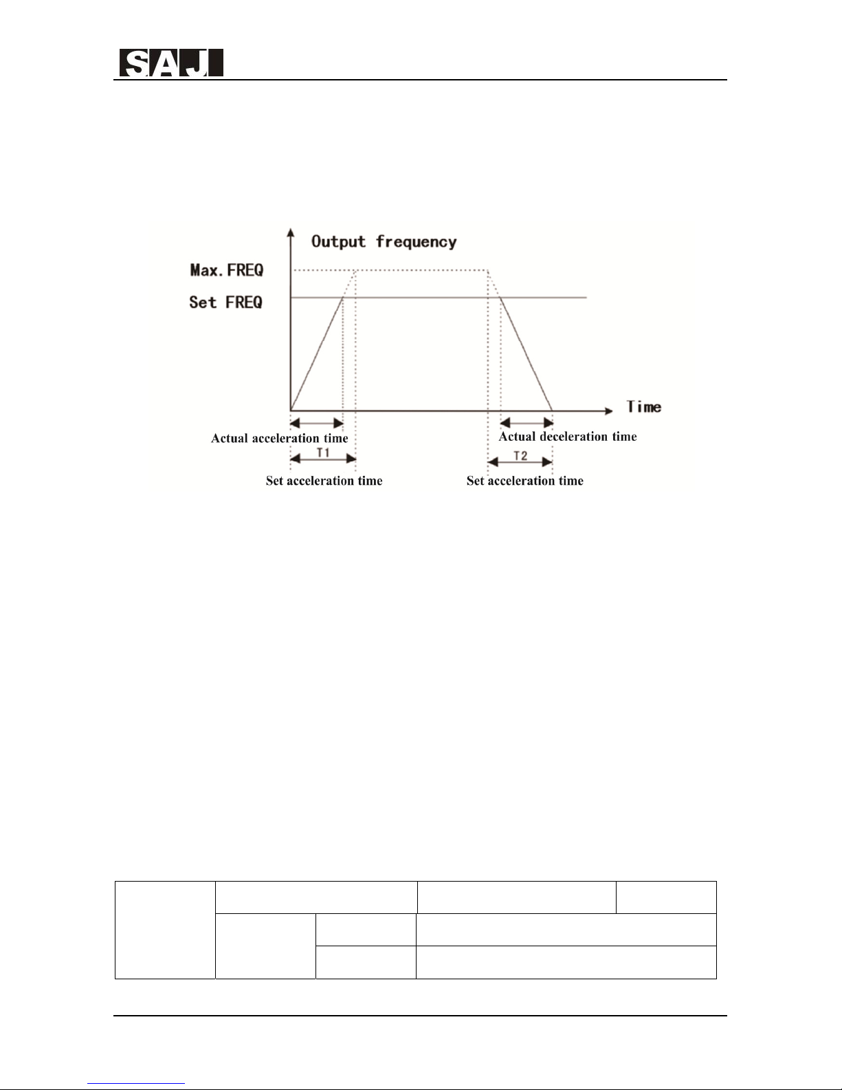
Acceleration time 1 means the needed time T1 that the VFD accelerate from 0Hz to
the Max. output frequency(F0.10).
F0.17
PWM mode selection Factory Setting 0
Setting
Options
0 PWM mode 1
1 PWM mode 2
2 PWM mode 3
8000m Series
- 64 -
Deceleration time 1 means the needed time T2 that the VFD decelerate from the
Max. output frequency(F0.10)to 0Hz.
See the diagram below:
Figure xx Sketch Map of Acceleration and Deceleration Time
Note: The difference between the actual acceleration/deceleration time and the set
acceleration/ deceleration time.
Totally 4 groups of acceleration and deceleration time are optional.
Group 1: F0.18, F0.19;
Group 2: F8.03, F8.04
Group 3: F8.05, F8.06
Group 4: F8.07, F8.08.
The acceleration and deceleration time can be selected through the multi-function
digital input terminals (F5.00~F5.03).
F0.20
Default Setting Restoring Factory Setting 0
Setting
Options
0 No operation
1 Restore to factory setting

8000m Series
- 65 -
2 Fault record clearing
O: No operation
1: The VFD restores all the parameters (except parameters from group F2) to factory
settings.
2: The VFD clears all the recent default records.
F0.21
Parameter lock and unlock Factory Setting 0
Setting
Options
0 Unlock parameter
1 Lock parameter
0:Unlock parameter
1: Lock parameter. After being locked, all the parameters can not be changed except
F0.21.
F0.22~F0.24 Reserved
F0.25
Cooling fan running method Factory Setting 1
Setting
Options
0 Keep running when power on
1 Reserved
0: Keep running when power on. When the VFD is powered on, the cooling fan
keeps running.
1: Automatic running. When the VFD is in operation, the cooling fan is also in
operation; when the VFD stops, the cooling fan will stop after 30s’ time delay.

8000m Series
- 66 -
5.2 F1 Group: Start and Stop Parameters
F1.00
Start mode Factory Setting 0
Setting Options
0 Start directly
1 DC braking first and then start
2 Speed tracing and start
0: Start directly: start from the frequency of start.
1: DC braking first and then start: DC braking first according to the set mode of
F1.03 and F1.04, then start from the frequency of start. This is suitable for the
occasion that the small inertial load may cause inversion at start up.
2: Speed tracing and start
The VFD will judge the rotational speed and direction of the electric motor, and then
start at relevant frequency traced from the rotational speed of the electric motor, thus
the rotating electric motor can start smoothly without surge. This is suitable for the
occasion that the large inertial load power off suddenly and start up again.
In order to ensure the performance of speed tracing and start, accurate parameters
for electric motor should be set. (See F2 group)
F1.01
Start frequency Factory Setting 1.50Hz
Setting Scope
0.00~10.00Hz
F1.02
Hold time of start frequency Factory Setting 0.0s
Setting Scope
0.0~50.0s
The VFD operates from the start frequency (F1.01), after the hold time of start
frequency (F1.02), the VFD will accelerate to the target frequency according to the
set time of acceleration. If the target frequency is lower than the start frequency,
the VFD will be in standby mode. The start frequency will not be restricted by the
lower limit frequency.

8000m Series
- 67 -
In order to ensure the torque of the VFD when starting, please set appropriate start
frequency. And to build up the magnetic flow when the electric motor is start,
please keep the start frequency for some time and then speed up.
If the frequency reference (frequency source) is lower than start frequency, the
VFD cannot start, and keep in standby mode.
When switching between forward and reverse direction of motor rotation, the hold
time of start frequency will not take effect. The hold time is not included in the speed
up time, but in the running time of simple PLC function.
F1.03
DC braking current before start Factory Setting 0.0%
Setting Scope
0.00~150.0%
F1.04
DC braking time before start Factory Setting 0.0s
Setting Scope
0.0~50.0s
DC barking before start is usually used to make the electric motor totally stop before
starting.
If the starting mode is DC barking before starting, the VFD will brake in DC current
according to the pre-set DC braking current, and the VFD will begin to run after the
pre-set time of DC braking current. If the pre-set time of DC braking current is 0, the
VFD will start directly without DC braking.
The larger the DC braking current is, the stronger the braking force.
DC braking current before start is a percentage with respect to the rated current of
the VFD.
F1.05
Stop mode Factory Setting 1
Setting Options
0 Deceleration to stop
1 Coast to stop
0: Deceleration to stop
After the stop command having taken effect, the VFD will reduce output frequency

8000m Series
- 68 -
in accordance with deceleration mode and the defined acceleration and
deceleration time, and the VFD will stop if the frequency reduced to 0.
1: Coast to stop
After the stop command having taken effect, the VFD immediately ceases to output.
The VFD will coast to stop according to mechanical inertia.
F1.06
Trigging frequency of DC braking at stop Factory Setting 0.00Hz
Setting Scope
0.00Hz~F0.10
F1.07
Waiting time before DC braking at stop Factory Setting 0.0s
Setting Scope
0.0~50.0s
F1.08
DC braking current at stop Factory Setting 0%
Setting Range
0.0~150.0%
F1.09
DC braking time at stop Factory Setting 0.0s
Setting Range
0.0~50.0s
Trigging frequency of DC braking at stop: in the process of deceleration and slowing
down, as soon as the VFD reaches this frequency, it will stop and go into the process
of DC braking.
Waiting time before DC braking at stop: before DC braking, the VFD ceases to
output, after this delay it begins DC braking. This function is used to avoid transient
fault caused by DC braking when the speed is too high.
DC braking current at stop: means the added current of DC braking. The bigger the
current is, the stronger the effect of DC braking. The braking current of the power of
halt is the percentage of rated current of the VFD.
DC braking time at stop: the added time for DC braking. If this value is 0, means
there is no DC braking process, the VFD will stop according to the set deceleration
and halt process.

8000m Series
- 69 -
F1.10
Dead-zone time between FWD and REV Factory Setting 0.0s
Setting Range
0.0~3600s
The transient time at zero output frequency in the process of setting the FWD and
REV transient process
As below:
Schematic Diagram of the Dead Time between FWD and REV
F1.11
Terminals control option when power on Factory Setting 0
Setting Options
0 Disabled
1 Enabled
F1.12-F1.17 Reserved
F1.18
Wake-up delay time (effective in sleep and
standby mode)
Factory Setting 0.0s
Setting Range
0.0~3600s
When F0.15=2, only if the time that the set frequency is equal or greater than the
lower limit frequency exceeds the set vale of F1.18 can the VFD begin to operate.
F1.19
Restart option after power-off Factory Setting 0
Setting Options
0~1
0: Restart is prohibited. This means that after powered off and powered on again, the
VFD will not start automatically.

8000m Series
- 70 -
1: Restart is allowed. This means that after powered off and powered on again, the
VFD will restore to the previous running status automatically. That is, if the VFD is
in running status before power-off, it will delay the waiting time(F1.20) of restart
after power-on next time and then start operation automatically (when controlled by
terminals, the running terminals must be in closed status),if the VFD is stopped
before power-off, it will not start automatically after powered on again.
F1.20
Waiting time of restart after
power-off
Factory Setting 0.0s
Setting Range
0.0~3600s
Note: when F1.19 is 1, this setting is effective.
F1.21
Over modulation option Factory Setting 0.0s
Setting Range
0.0~3600s
0:Over modulation function invalid
1:Over modulation function valid
This function is suitable for the working conditions that the VFD increases the
output voltage by increasing the utilization rate of its own bus bar voltage in long
term low voltage of power grid and long term overload.
5.3 F2 Group: Motor Parameters
F2.00
Drive model Factory Setting 0
Setting Options
0 General model (G)
1 Pump model (P)
Note: Users can set the parameters of this group to change model type and take
advantage of the combination of G/P. The 220V inverter only has General model
(G).
0: Suitable for the constant torque load with the appointed parameters

8000m Series
- 71 -
1: Suitable for the variable torque load (load of draught fans, water pumps)of the
appointed parameters
F2.01
Motor rated power Factory Setting 0
Setting Range
0.4~7.5kW
F2.02
Motor rated frequency Factory Setting 50.00Hz
Setting Range
10.00Hz~F0.10
F2.03
Motor rated rotation
speed
Factory Setting Defined by inverter model
Setting Range
0~36000rpm
F2.04
Motor rated voltage Factory Setting Defined by inverter model
Setting Options
0~480V
F2.05
Motor rated current Factory Setting
Different according to inverter
model
Setting Range
0.8~2000A
F2.06
Motor stator resistance Factory Setting Defined by inverter model
Setting Range
0.001~65.53Ω
F2.07
Motor rotator resistance Factory Setting Defined by inverter model
Setting Range
0.001~65.53Ω
Attention
Please set the parameters according to the nameplate of the electric motor.
To make sure the superior control performance of vector control, please set accurate
parameters, accurate parameter identification comes from the right settings of rated
parameters of the electric motor.
In order to ensure control performance, please configure the electric motor according to the
standards of electric motor adaption of the VFD. If the gap between motor power and the
standard adaptation motor is too large, the control performance of the VFD will decline
sharply.

8000m Series
- 72 -
F2.08
Motor stator inductance Factory Setting Defined by inverter model
Setting Options
0.1~6553mH
F2.09
Motor rotator mutual
inductance
Factory Setting Defined by inverter model
Setting Range
0.1~6553mH
F2.10
Motor no-load current Factory Setting Defined by inverter model
Setting Range
0.1~655.3A
After automatic tuning of electric motor finished normally, the setting values of
F2.06~F2.10 will update automatically.
Every time after changing the rated power of F2.01, the VFD will restore the
standard default parameters of F2.06~F2.10.(Quadru-pole Y series asynchronous
motor)
If the spot situation do not allow tuning for electric motor, it is possible to refer to the
known parameters of the electric motors of same type and input the parameters
manually.
F2.11~F2.12 Reserved

8000m Series
- 73 -
5.4 F3 Group: Vector Control Parameters
F3.00
Proportional gain 1 of speed loop Factory Setting 20
Setting Options
0~100
F3.01
Integral time 1 of speed loop Factory Setting 0.50s
Setting Options
0.01~10.00s
F3.02
Low frequency point of switch Factory Setting 5.00Hz
Setting Options
0.00Hz~F3.05
F3.03
Proportional gain 2 of speed loop Factory Setting 25
Setting Options
0~100
F3.04
Integral time 2 of speed loop Factory Setting 1.00s
Setting Options
0.01~10.00s
F3.05
High frequency point of switch Factory Setting 10.00Hz
Setting Options
F3.02~F0.10
When the VFD is running at different frequency, different speed loop PI parameters
can be selected. If the running frequency is lower than the value of low frequency
point of switch (F3.02), the speed loop PI adjustable parameters should be F3.00 and
F3.01.If the running frequency is higher than the value of high frequency point of
switch (F3.05), the speed loop PI adjustable parameters should be F3.03 and F3.04.
When the operation frequency is between the low frequency point of switch and
high frequency point of switch, the PI parameters are linear switching of the two
group PI parameters.

8000m Series
- 74 -
By adjusting the proportion coefficient and integral time of speed regulator, the
dynamic response speed of vector control can be adjusted. Increase proportional
gain and reduce integral time can both speed up the dynamic response of speed loop.
The conditions of too large proportional or too short integral time will cause system
oscillation.
Recommended adjustment method:
If the factory parameters cannot meet the requirements, conduct trimming on the
basis of factory parameters, firstly increase the proportional gain and ensure that the
system will not oscillate, then reduce integral time so that the system owns fast
response and small overshoot.
Note: Inappropriate setting of PI parameters will lead to large speed overshoot, even
cause over-voltage fault when overshoot falls back.
As for no speed sensor vector control, this parameter is used for adjusting rotating
speed of electric motor. When the work load of electric motor is heavy and the
speed is too slow, increase this parameter, contrarily decrease this parameter.
As for speed sensor vector control, this parameter can adjust the out put current of
the VFD in same workload.
F3.06
Coefficient of slip compensation at VC
control mode
Factory Setting 100%
Setting Options
50%~200%

8000m Series
- 75 -
Under speed control mode, the VFD output the maximum value of torque, set
100.0% which is correspondent to the rated output(or rated torque) current of the
VFD.
0:no detection
1: Overload pre-alarm is detected effective in operation (including acceleration,
deceleration and constant speed), go on operation after detection
2: Overload pre-alarm is detected effective in operation (including acceleration,
give alarm (E023) and stop after detection
3: Overload pre-alarm is detected effective in constant speed, go on operation after
detection
4: Overload pre-alarm is detected effective in constant speed, go on operation after
detection, give alarm (E023)and stop after detection
F3.07
Upper limit torque Factory Setting 150%
Setting Options
0.0 ~200.0% (Drive rated current)
F3.08-F3.09 Reserved
F3.10
Pre-alarm option when overload Factory Setting 1
Setting Options
0 ~4
F3.11
Detecting level of pre-alarm when
overload
Factory Setting 150.00%
Setting Options
1.0~200.0% (referred to inverter
rated current)
F3.12
Detecting time of pre-alarm when
overload
Factory Setting 1s
Setting Options 0~600s

8000m Series
- 76 -
5.5 F4 Group: V/F Control Parameters
This group of codes are only effective for V/F control(F0.00=1), but are invalid for
vector control.
V/F control is fit for fans,pumps and other general loads, or the situation of one
VFD drives several electric motors, or the situation that the frequency of the VFD
has too much difference with that of the electric motor.
F4.00
V/F curve selection Factory Setting 0
Setting Options
0 Linear curve
1 User-defined curve
2 1.3 square torque-step-down curve
3 1.7 square torque-step-down curve
4 2 square torque-step-down curve
0:Linear curve, suitable for situations of ordinary constant torque load.
1:User-defined curve,suitable for special loads such as water extractor,
hydro-extractor etc.Now by setting the parameters of F F4.03~ F4.08, you can get
any curve about V/F relations.
2:1.3 square torque-step-down.
3:1.7 square torque-step-down.
4: 2 square torque-step-down curve.
F4.01
Torque boost Factory Setting 3.0%
Setting Options
0.0 %(auto) 0.1% ~30.0%
F4.02
Torque boost cut-off frequency Factory Setting 20.0%
Setting Options
0.0~50.0% (relative to motor rated
frequency)
In order to make up for the feature of low-frequency torque of V/F control, do a lift

8000m Series
- 77 -
makeup for the output voltage of the VFD when it is in low frequency.
If the settings for torque boost is too high, the electric motor will become too hot
and the VFD will be in over-current. Generally, when setting the torque boost, do
not exceed 8.0%.
Adjust this parameter effectively can avoid over-current when start up. As for large
load, it is recommended to increase this parameter, and reduce this when the load
is light.
When torque is increased to 0.0, the VFD will in the status of automatic torque boost,
the VFD will automatically calculate the needed torque boost value according to the
parameters of stator resistance etc.
Torque boost and torque cutoff frequency:under this frequency, the torque of torque
boost is effective, but if exceed this set frequency, the torque boost will be invalid.
Diagram of Manual Torque Boost
V1: Voltage of manual torque boost
F1: Cutoff frequency of torque boost
vb: Max.output voltage
Fb: The rated operating frequency

8000m Series
- 78 -
F4.03
V/F frequency 1 Factory Setting 5.00Hz
Setting Options
0.00Hz~F4.05
F4.04
V/F voltage 1 Factory Setting 12.0%
Setting Options
0.0%~100.0%
F4.05
V/F frequency 2 Factory Setting 10.00Hz
Setting Options
F4.03~F4.07
F4.06
V/F voltage 2 Factory Setting 26.0%
Setting Options
0.0%~100.0%
F4.07
V/F frequency 3 Factory Setting 20.00Hz
Setting Options
F4.05~motor rated frequency
F4.08
V/F voltage 3 Factory Setting 45.0%
Setting Options
0.0%~100.0%
The 6 parameters of F4.03~F4.08 define multistage V/F curve.
The setting values of V/F curves are determined by the load characteristics of the
electric motor.
Note: the relationships of the three voltage and frequency must meet: V1<V2<V3,
F1<F2<F3. When the frequency is low, high voltage setting may cause over-heating
of motor or even burn the motor, and the VFD may lose speed because of
over-current or get into over-current protection.
V1 ~ V3: Voltage percentage of 1~3 multistage V/F curve
F1 ~ F3: frequency point of 1~3 multistage V/F curve
Fb: rated motor frequency F2.02
This is effective for V/F control. Setting this parameter can make up the speed
F4.09
Coefficient of V/F Slip compensation Factory Setting 0.00%
Setting Options
0.0%~200.0%
8000m Series
- 79 -
deviation because of load in V/F control, and make sure that the speed of electric
motor can remain stable when the load changes. When V/F speed deviation
compensation coefficient is set as 100%, this means if the electric motor is in rated
load, the compensated speed deviation will be the rated slip of the electric motor.
As for the rated speed deviation of the electric motor, the VFD will get the value
by automatic calculation of the rated frequency of electric motor and rated speed of
F2 group. Refer to the following principles to adjust the speed deviation
coefficient:when the load is the rated load, and set the speed deviation coefficient
as 100%, the rotational speed of the electric motor driven by VFD will basically
close to the given speed.
When the electric motor is no-load or is operating in light load, by testing the load
current and adjusting output voltage properly to realize the purpose of automatic
energy saving.
Note: this function is specially effective for loads like fans, pumps, etc.
Most electric motors are easy to have current oscillations when operate in some
certain frequencies, some of the motors may not operate stably,or even cause
F4.10
Energy-saving selection Factory Setting 0
Setting Options
0 Disabled
1 Enabled automatically
F4.11 Reserved
F4.12
Low-frequency threshold of restraining
oscillation
Factory Setting 1
Setting Options
0~10
F4.13
High-frequency threshold of restraining
oscillation
Factory Setting 0
Setting Options
0~10

8000m Series
- 80 -
over-current to the VFD. F4.16 can restrain oscillation, when set F4.12 and F4.13
into small values, the outcome of restraint will be prominent, and the current will
increase obviously, however, when set these values too high, the outcome of
restraint will be weak.
F4.14 Reserved
F4.15 is the demarcation point of frequency of F4.12 and F4.13.
Under V/F control, when it is needed to stop quickly and there is no brake resistance,
select “only invalid under slowdown” can greatly reduce the possibility of over
voltage fault and alarm. While in the condition that brake resistance exists and there
is no need to slow down quickly, please select “Valid all the time”.
F4.15
Boundary frequency of restraining oscillation Factory Setting 30.00Hz
Setting Options
0.00Hz~F0.10 (Maxi.
Frequency)
F4.16 Reserved
F4.17
AVR function selection Factory Setting 1
Setting Options
0 Invalid
1 Valid all the time
2 Only invalid during deceleration

8000m Series
- 81 -
5.6 F5 Group Input Terminals Parameters
The standard unit of a 8000m series VFD has 4 multi-function digit input terminals
and 1 analog input terminal.
F5.00 M1 terminal function Factory Setting 1
F5.01 M2 terminal function Factory Setting 2
F5.02 M3 terminal function Factory Setting 7
F5.03 M4 terminal function Factory Setting 0
F5.04 Reserved Factory Setting 0
F5.05 Reserved Factory Setting 0
F5.06 Reserved Factory Setting 0
F5.07 Reserved Factory Setting 0
F5.08 Reserved Factory Setting 0
F5.09 Reserved Factory Setting 0
These parameters are used to set the corresponding functions of digit multi-function
input terminals or virtual multi-function digital input, the optional functions are as
follows:
Setting
Values
Functions Descriptions
0 No function
Even has signal input, the VFD will not act. The
unused terminals can be set as no function in case
of preventing malfunction.
1 Run forward (FWD)
Control terminals for running forward and
reverse.
2 Run reverse (REV)
3 3-wire control
The terminal determines the operation mode of
AC drive as 3-wire control. For details, please
refer to the description of function code of F5.11
3-wire control.
4 Jog forward (FJOG) FJOG is jog forward operation, RJOG is jog

8000m Series
- 82 -
5 Jog reverse (RJOG)
reverse operation. As for the frequency and the
acceleration and deceleration time of jog
operation, refer to the detailed description of
function code of F8.00, F8.01 and F8.02.
6 Coast to stop
The VFD blocks output, the shutdown process of
electric motor is not controlled by the VFD. As for
large inertia loads and no requirements for the
time of shutdown, this is the usual method. The
definition of this method is the same as that
defined in F1.05.
7 Fault reset (RESET)
External fault reset function. This function is the
same as that of RESET on keyboard. Remote fault
reset is implemented by this function.
8 Pause running
The VFD slows down, but all the operating
parameters are in memory state, such as PLC, the
swing frequency, and PID parameters. As soon as
this signal disappears, the VFD returns to the
status before shutdown.
9 External fault input N. O.
Set the terminal as this function, as this terminal
closed, the VFD will report E015 fault and stop.
10
Frequency setting
increasing(UP)
If the frequency is determined by external
terminals, the terminals with the two functions are
used as increment and decrement commands for
frequency modification.
When the frequency source is digital setting, they
are used to adjust the frequency.
11
Frequency setting
decreasing(DOWN)
12 Clear UP/DOWN setting
Clear the frequency values set through
UP/DOWN.
13
Frequency setting source
switch between X and Y
If the present frequency source is X, switch to
frequency source Y.
14
Frequency setting source
switch between X and
(X+Y)
If the present frequency source is X, switch to
frequency source X+Y.
15
Frequency setting source
switch between Y and
If the present frequency source is Y, switch to
frequency source X+Y.

8000m Series
- 83 -
(X+Y)
16 Multi-step speed terminal 1
The setting of 16 speeds can be implemented
through combinations of these four terminals. For
details, please refer to annex 1.
17 Multi-step speed terminal 2
18 Multi-step speed terminal 3
19 Multi-step speed terminal 4
20 Multi-step speed pause
Shield the terminal function of multi-step speed
selection, and maintain the setting value to current
status.
21
Acceleration/deceleration
time selection terminal 1
Select 4 settings of acceleration and deceleration
time by the combine of the digit status of these
two terminals.
22
Acceleration/deceleration
time selection terminal 2
23
Restart simple PLC after
pause
Restart the process of simple PLC and clear up the
memory information of the previous PLC
24 Simple PLC pause
Executing process of simple PLC pauses, operate
all the time at the current speed
25 PID pause
PID is invalid temporarily, the VFD maintains the
present output of frequency, will not adjust by
PID.
26
Swing frequency pause
(maintain at current
frequency)
The VFD maintains temporarily at the present
output of frequency
27
Reset after swing frequency
pause (reset to central
frequency)
The frequency of the VFD resets to central
frequency
28 Counter reset This will clear up the status of counter
29 Reserved
30
Acceleration/deceleration
prohibited
Keep the VFD not influenced by outer
signals(except the stop command), maintains the
present output frequency.
31 Counter triggering
32
Clear UP/DOWN setting
temporarily
When the terminal is closed, this can clear up the
set frequency of UP/DOWN; when the terminal is

8000m Series
- 84 -
disconnected, it will go back to the frequency of
UP/DOWN setting.
33 Reserved
34 Length counting input
Length counting by the input signal. If the signal
of counting input is a pulse signal, it is needed to
transfer it into a discrete signal by a relay(the
frequency of input signal should be lower than
200Hz)
35 Length counting clear up Clear up the present values of counting meter
36
Control command source
switching
When the terminal is defined as this function, and
when terminal input is switching, it can select
command source between keypad command and
terminal command.
37 Terminal input delay output
When the terminal is defined as this function, the
close time of this terminal exceeds the setting
value of F8.21, and the function of the digital
output such as relay is defined as 16, the digital
output will be activated as closed, or it will
disconnect
38 Reserved

8000m Series
- 85 -
Attached Table 1- Instruction of Multi-step speed
K4 K3 K2 K1
Freque
ncy setting
Correspondi
ng parameters
OFF OFF OFF OFF Multi-ste
p speed 0
FD.02
OFF OFF OFF ON Multi-ste
p speed 1
FD.04
OFF OFF ON OFF Multi-ste
p speed 2
FD.06
OFF OFF ON ON Multi-ste
p speed 3
FD.08
OFF ON OFF OFF Multi-ste
p speed 4
FD.10
OFF ON OFF ON Multi-ste
p speed 5
FD.12
OFF ON ON OFF Multi-ste
p speed 6
FD.14
OFF ON ON ON Multi-ste
p speed 7
FD.16
ON OFF OFF OFF Multi-ste
p speed 8
FD.18
ON OFF OFF ON Multi-ste
p speed 9
FD.20
ON OFF ON OFF Multi-ste
p speed 10
FD.22
ON OFF ON ON Multi-ste
p speed 11
FD.24
ON ON OFF OFF Multi-ste
p speed 12
FD.26
ON ON OFF ON Multi-ste
p speed 13
FD.28
Reserved FD.30
Reserved FD.32

8000m Series
- 86 -
Attached Table 2 Instruction of Acceleration/Deceleration Time
Terminal 2 Terminal 1
Seletion of
accleration/decelerat
ion time
Corresponding
parameters
OFF OFF Acceleration
time1
F0.18、F0.19
OFF ON Acceleration
time2
、
F8.03 F8.04
ON OFF Acceleration
time3
、
F8.05 F8.06
ON ON Acceleration
time4
、
F8.07 F8.08
Sensitivity setting of the multi-function digital input terminals: If the digital input
terminals are interfered and result in malfunction in some cases, increase this
parameter setting for better anti-interference, but maybe the terminal sensitivity will
then decrease also.
This parameter defines 4 control modes of VFD by terminal inputs.
0: 2-wire control mode 1. This mode is the most usual one. By terminal command
of M1(FWD) and M2(REV), the motor will run forward or reversed as shown in
the following table and wiring diagram.
F5.10
On/off filter times Factory Setting 5
Setting Options
1~10
F5.11
Terminal control mode Factory Setting 0
Setting Options
0:2-wire control mode 1
1:2-wire control mode 2
2:3-wire control mode 1
3:3-wire control mode 2

8000m Series
- 87 -
K1 K2 Motor Control
OFF OFF STOP
ON OFF FORWARD
OFF ON REVERSE
ON ON STOP
1: 2-wire control mode 2. In this mode,M1(FWD) is the enable terminal and the
direction is determined by M2(REV).
K1 K2 Motor Control
OFF OFF STOP
OFF ON STOP
ON OFF FORWARD
ON ON REVERSE

8000m Series
- 88 -
2: 3-wire control mode 1. In this mode,Mn is the enable terminal and the direction
is controlled respectively by M1(FWD), M2(REV).
To start a motor, close and enable Mn terminal, then with the rising edge of pulse
input of M1 or M2 terminals, the motor will run forward or reverse.
To stop VFD, it should be done by disconnecting Mn terminal input signal.
Note:
SB1: FWD switch
SB2: STOP switch
SB3: REV switch
Mn is one of the multi-function digital input terminals, and its corresponding
terminal function should be set as 3, which means “3-wire control mode”.
3: 3-wire control mode 2. In this mode, Mn is the enable terminal. The running
command is controlled by M1(FWD) and the direction is controlled by M2(REV).
To start a motor, close and enable Mn terminal, the rising edge of pulse input of
M1 is for running command, and M2 input is for direction control.
The STOP command is done by disconnecting Mn terminal signal.
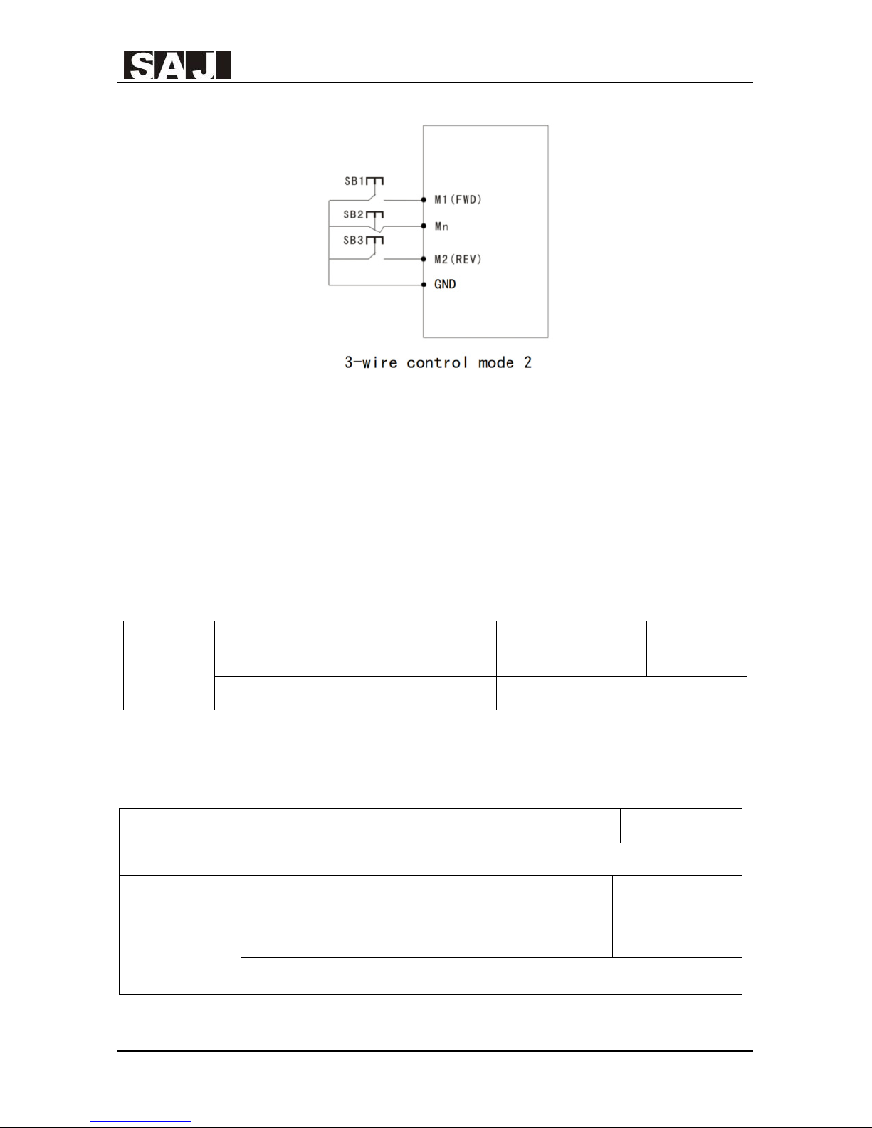
8000m Series
- 89 -
Note:
SB1: RUN switch
SB2: STOP switch
SB3: FWD/REV switch
Mn is one of the multi-function digital input terminals, and its corresponding
terminal function should be set as 3, which means “3-wire control mode”.
This parameter is used to adjust the frequency changing rate of terminal
UP/DOWN; the rate unit is Hz/s.
F5.13
AVI lower limit Factory Setting 0.00V
Setting Options
0.00V~10.00V
F5.14
Setting value
corresponding to AVI
lower limit
Factory Setting 0.0%
Setting Options
-100.0%~100.0%
F5.12
Frequency changing rate through
UP/ DOWN terminal adjusting
Factory Setting 0.50Hz/s
Setting Options 0.01~50.00Hz/s

8000m Series
- 90 -
F5.15
AVI upper limit Factory Setting 10.00V
Setting Options
0.00V~10.00V
F5.16
Setting value
corresponding to AVI
upper limit
Factory Setting 100.0%
Setting Options
-100.0%~100.0%
F5.17
AVI input filter time Factory Setting 0.10s
Setting Options 0.00s~10.00s
F5.18~F5.22 Reserved
These parameters are used to define the relationship between the analog input and
the corresponding setting. When the analog input exceeds the scope between the
defined upper and lower input limits, the analog value is calculated as the upper or
lower input limits reached.
When the analog input is current input, 1 mA current corresponds to 0.5 V voltage.
In different applications, 100% of analog input corresponds to different nominal
values. For details, refer to the description of different applications.
The following examples illuminate the setting situations.
8000m Series
- 91 -
F5.23
M1 On delay Factory Setting 0.0s
Setting Options
0.0s ~ 6000.0s
F5.24
M1 Off delay Factory Setting 0.0s
Setting Options
0.0s ~ 6000.0s
F5.25
M2 On delay Factory Setting 0.0s
Setting Options
0.0s ~ 6000.0s
F5.26
M2 Off delay Factory Setting 0.0s
Setting Options
0.0s ~ 6000.0s
F5.27~F5.32 Reserved
On delay of digital input terminal means the delay time for the setting function of
the input terminal to take effect after the input switch is closed.
Off delay of digital input terminal means the delay time for the setting function of
the input terminal not to take effect after the input switch is opened.

8000m Series
- 92 -
5.7 F6 Group Output Terminals Parameters
8000m series VFD provides 1 multi-functional digital output (with optical coupler),
1 multi-functional relay output, 1 multi-functional analog output.
F6.00 MO1 output selection Factory Setting 1
F6.01 Reserved
F6.02 Relay 1 output selection Factory Setting 3
F6.03~F6.04 Reserved
The function options for the multifunctional digital and relay outputs are shown as
following table:
Setting
value
Function Instructions
0 No output The terminal has no function.
1 VFD FWD running
When the VFD is in FWD running status,
the output becomes ON.
2 VFD REV running
When the VFD is in REV running status, the
output becomes ON.
3 Fault output
When the VFD stops due to a fault, the
output becomes ON.
4
Frequency detecting
level FDT output
For details, please refer to F8.12,F8.13
5 Frequency reached For details, please refer to F8.14
6
Running at zero
speed
If the VFD runs with the output frequency of
0, the output becomes ON.
7
Upper limit
frequency reached
If the running frequency reaches the upper
limit, the output becomes ON.
8
Lower limit
frequency reached
If the running frequency reaches the lower
limit, the output becomes ON.
9
Frequency setting
value less than lower
limit frequency
When the selected frequency reference is
less than the frequency lower limit, the
output becomes ON.
10 FDT reached When the selected frequency reference
8000m Series
- 93 -
Setting
value
Function Instructions
reach the FDT level, the output becomes
ON.
11
Accumulative
running time reached
If the accumulative running time of the
VFD exceeds the time set in F8.17, the
output becomes ON.
12
PLC cycle
completed
When simple PLC operation completes one
cycle, the output becomes on as a pulse
signal with width of 250 ms.
13
VFD overload
pre-alarm
The output becomes ON after the pre-alarm
time as the VFD reaching pre-alarm
threshold value.
14
User Customized
Output
Users can customize the output function,
refer to F6.14~f6.18
15
Running frequency
detection
When the running frequency is less or equal
to the setting of F8.22, or is larger or equal
to the setting of F8.23, the output becomes
ON; When the output frequency is between
F8.22 and F8.23, the output becomes OFF.
16
Terminal input delay
output
As a multifunction digital input is set as the
function of Terminal Input Delay Output, if
the time-lasting exceeds the time setting of
F8.21 after input is closed, the output
becomes ON.
17 VFD stand-by
When the VFD is Power on and is in STOP
status without any fault occurring (include
LU fault, the output becomes ON; After the
VFD turns into running, or there is a fault,
the output becomes OFF.
8000m Series
- 94 -
F6.09 AM output selection Factory Setting 0
The signal scope of analog output FM is 0V~10V or 0mA~20mA.
The analog output scope calibration is as following table.
Setting
value
Function
Analog output 0.0%~100.0%
Corresponding value
0 Running frequency 0~Maximun output frequency
1 Setting frequency 0~Maximun output frequency
2
Running rotation
speed
0~Running rotation speed correspond to
maximum output frequency
3 Output current 0~2 times of motor rated current
4 Output voltage 0~1.2 times of VFD rated voltage
5~7 Reserved
8
Analog AVI input
value
0~10V
9~10 Reserved
F6.05
FM output lower limit Factory Setting 0.0%
Setting Options 0.0~100.0%
F6.06
FM lower limit
corresponding to output
Factory Setting 0.00V
Setting Options 0.00V~10.00V
F6.07
FM output upper limit Factory Setting 100.0%
Setting Options 0.0~100.0%
F6.08
FM upper limit
corresponding to output
Factory Setting 10.00V
Setting Options 0.00V~10.00V
F6.10~F6.13 Reserved
The above function codes define the corresponding relation between the FM output
range and the analog output signal limits. When the output exceeds the scope
between the defined upper and lower input limits, the analog output signal is

8000m Series
- 95 -
calculated as the upper or lower input limits reached.
When the analog output is current output, 1mA current corresponds to 0.5V
voltage.
In different applications, 100% of analog output corresponds to different nominal
values. For details, refer to the description of different applications.
F6.14
User defined output
variability option (EX)
Factory Setting 0
Setting Options
0:Running frequency
1:Setting frequency
2:DC bus voltage
3:Output current
4:Output voltage
5:Sign of start and stop status
6:Sign of control status
7:Counter value
8:Counting meter value
9:Inverter module temperature
10:AVI input value
11:Reserved
This parameter is used as the selection of reference variable for the user defined
output. The selected EX is used as the comparison value.

8000m Series
- 96 -
F6.15
Comparison method of
user defined output
Factory Setting 0
Setting Options
Units digit: comparison test
method
0: Equal (EX==X1)
1: Equal or greater than
2: Equal or less than
3: Interval comparison
(X1≤EX≤X2)
4:Bits test (EX&X1=X2)
Tens digit : output method
0: False value output
1: True value output
Unit digit selection defines the comparison method: Take the variable selected by
F6.14 as the test object and compare it with the comparison value set by F6.17 and
F6.18.
Tens digit selection defines output method: Selection of the false or true value
output mode. The false value output mode means if it cannot meet the comparison
condition, it will output, and if it can meet the condition it won’t output. The true
value output mode means if it can meet the comparison condition, it will output,
and if it cannot meet the condition it won’t output.
F6.16
User defined output
dead zone
Factory Setting 0
Setting Options 0~65535
When the comparison method of F6.15 is greater than /equal to or less than or
equal to, F6.16 is used to define the dead zone that take comparison value X1 as
zone center. The dead zone only takes effect for F6.15 comparison method 1 and 2,
not for method 0, 3 and 4. For example, When F6.15 is set as 11, as the EX
increases from zero and become greater than or equal to X1 + F6.30, the output is
valid; when the EX decreased until less than or equal to X1.F6.30, output is
invalid.

8000m Series
- 97 -
F6.17
Output comparison value
X1
Factory Setting 0
Setting Options 0~65535
F6.18
Output comparison value
X2
Factory Setting 0
Setting Options 0~65535
This two parameters is used to set the comparison value of user-defined output.
The following is an example of user-defined output:
1. When the setting frequency is required to be greater than or equal to 20.00HZ, the
relay is closed;
Set the parameters as follows: F6.02 = 14, F6.28 = 1, F6.15 = 11, F6.16 = 0, F6.31 =
2000;
2. When the bus voltage is require to be less than or equal to 500.0V, the relay is
closed; In order to avoid relay operates frequently when the detection voltage
fluctuate ±5V at 500.0V, it requires to process the dead intervalwithinthe range of
(500.0-5.0) - (500.0 + 5.0) .
Set the parameters as follows: F6.02 = 41, F6.28 = 2, F6.29 = 01, F6.30 = 50, F6.31
= 5000;
3. When the AC drive is reversed, the relay is closed:
Set the parameters as follows: F6.02 = 41, F6.28 = 5, F6.29 = 14, F6.31 = 8, F6.32 =
8;
4. When AI1 input is greater than 3.00V and less than or equal to 6.00V, the relay is
closed:
Set the parameters as follows: F6.02 = 41, F6.28 = 13, F6.29 = 13, F6.31 = 300,
F6.32 = 600

8000m Series
- 98 -
5.8 F7 Group Display Interface Parameters
F7.00
User Password
Factory Setting 0
Setting Options 0~9999
The password protection will take effect after this parameter is set as a non zero
digit.
0000: Clear the password being set before, and disable password protection;
Restoring factory setting can also clear password.
After password is set and has take effect, if the password isn’t correct, user can not
enter parameter menu display. Only give a correct password to enter parameter
display and edition mode. The password being set must be keep in mind.
Password protection will take effect 1 minute after withdrawing from parameter
edition mode. While the password protection has been enabled, “0.0.0.0” will be
displayed first as the PRGM is pressed for entering parameter edition mode.
Password must be input correctly, or the edition mode will never been enabled.
F7.01~F7.03 Reserved
F7.04
RUN/STOP key stop
function
Factory Setting 0
Setting Options
0:Only valid for keypad setting
1:Valid for both keypad setting and
terminals setting
2:Valid for both keypad setting and
communication interface setting
3:Valid for all control mode
F7.05 Reserved
F7.06 Running status display Factory Setting 35

8000m Series
- 99 -
selection 1
Setting Options
0~0xFFFF
BIT0:Running frequency
BIT1:Setting frequency
BIT2:DC bus voltage
BIT3:Output voltage
BIT4:Output current
BIT5:Running speed
BIT6:Linear speed
BIT7:Reserved
BIT8:Reserved
BIT9:PID setting value
BIT10:PID feedback value
BIT11:Input terminals status
BIT12:Output terminals status
BIT13:Reserved
BIT14:Counter value
BIT15:Current step of multi-step
speed and PLC
F7.07
Running
status display
selection 2
Factory Setting 0
Setting Options
1~0xFFFF
BIT0:AVI value
BIT1: Reserved
BIT2: Reserved
BIT3: Motor overload ratio
BIT4: Inverter overload ratio
BIT5: Running time
BIT6: Counting meter value
BIT7~BIT15: Reserved
F7.08
Stop status display
selection
Factory Setting 3
Setting Options
0~0xFFFF
BIT0: Setting frequency
BIT1: DC bus voltage
BIT2: Input terminal status
 Loading...