


Version code
:8000B-E201208-1MB
8000B Series Enhanced Inverter
User Manual

-I-
8000B Series
TABLE OF CONTENTS
Notes for Safe Operation………………………………........…………01
Notes for Other Important Operations………………...............……06
Chapter 1 Select the Right Type……………………............………08
1.1 Description of Model……………………………………….........................…08
1.2 Description of Nameplate…………………………………..................………08
1.3 8000B Series Inverter Table……………………………..............……………09
1.4 Specications of 8000B Series Inverter……………….................…………10
1.5 Outline Drawing and Dimensions……….............................................……12
1.6 Selection Instruction Table of Brake Resistor and Brake Unit…….........…17
Chapter 2 Mechanical and Electric Installation………….............18
2.1 Mechanical Installation………………………………….....................………18
2.2 Electric Installation………………………………...........................…………19
Chapter 3 Wiring…………………………...................………………23
3.1 Standard Wiring Diagram………………………….................………………23
3.2 Terminal Descriptions of Main Circuit and Control Circuit…...............……27
Chapter 4 Operation……………………………………….............…32
4.1 Keypad Description………………………………..........................…………32
4.2 Operation Process…………………………………............................………33
Chapter 5 Function Code Table…………….............………………36
Chapter 6 Trouble Shooting………………………............…………64
6.1 Fault and Trouble Shooting………………...........................................……64
6.2 Common Faults and Solutions……………….....................…………………68
Chapter 7 Data Address Table of Function Code...…............…..69

-II-
8000B Series
PRECAUTION
Never modify the products. Failure to observe this warning
can result in electrical shock or personal injury. SAJ is not
responsible for any modification of the frequency products
made by the user, since that will void your guarantee.

-01-
8000B Series
Notes for Safe Operation
Read this instruction manual thoroughly before installation, operation,
maintenance or inspection of the frequency inverters. In this manual, safe
operation are classied as “WARNING” or “CAUTION”.
WARNING
Indicate a potentially dangerous situation which, if not avoided, could result
in death or serious injury to personnel.
CAUTION
Indicate a potentially dangerous situation which, if not avoided, could result
in minor or moderate injury and damage to equipment. It may also be used
for warning against unsafe practices.
Even items described as ( CAUTION) may result in a vital accident in some
situations. Please follow these important notes:
NOTE
These are steps to be taken to ensure proper operation.
Before Installation
WARNING
Do not install or operate any frequency inverter that is damaged or has
missing parts.
Choose the motor of insulation class B or above. Otherwise it may cause
an electrical shock.
-02-
8000B Series
Installation
WARNING
Instal l the fre quenc y inver ter on nonf lammabl e ma teri al like metal.
Otherwise it may cause a fire.
WARNING
Make sure that the mounting environment away from metal dust. Otherwise
it may cause damage to the frequency inverter.
CAUTION
When mount over two inverters in the same cabinet or enclosure, install a
fan or other cooling device to keep the temperature inside below 50℃.
Do not let the conductor head or screws fall into the inside of the inverter.
Otherwise it may cause damage to the inverter.
Wiring
WARNING
Ensure only qualified personnel to operate. Otherwise it can cause an
electrical shock.
Make sure the inverter is isolated from power supply by the circuit breaker.
Otherwise it may cause a fire.
Verify that the power supply is turned OFF before start wiring. Otherwise it
may cause an electrical shock or fire.
Make sure that the ground terminal is grounded correctly. Otherwise it may
cause an electrical shock.

-03-
8000B Series
CAUTION
Never connect the AC power supply to output terminals U, V and W.
Otherwise the inverter will be damaged and the guarantee is invalid.
Make sure that wiring conform to EMC requirements and local power safe
standard. Make sure to use right wire according to this instruction manual.
Otherwise it may cause an accident.
Braking resistor or braking unit cannot be directly connected to DC bus
terminals (P+) and (N-). Otherwise it may cause a fire.
Before Turn on the AC Power Supply
WARNING
Make sure that the voltage of inverter conforms to the local power supply
voltage. Verify that the wiring of input and output is correct and there is no
short-circuit in peripheral circuit. Tighten the terminal screws. Other wise
these may cause damage to the inverter.
Turn on the input AC power only af ter the front cover is put correctly.
Otherwise it may cause an electrical shock.
CAUTION
Never perform a hi-pot or withstand voltage test of the inverter. Otherwise
it may cause damage to the inverter.
Make sure that the optional parts are connected correctly. Otherwise it
may cause damage to the inverter.

-04-
8000B Series
When the Power is On
WARNING
Do not open or remove the front cover when operation. Otherwise it may
cause an electrical shock.
Never touch the inverter and optional parts by wet hands. Never touch the
connection terminals. Otherwise it may cause an electrical shock.
When the power is on, the inverter will automatically check the power
supply circuit. Do not touch U, V, W terminals and motor connection
terminals. Otherwise it may cause an electrical shock.
CAUTION
It is dangerous for the personnel to approach the motor and load during
rotation of the motor. Do not change the factor y parameters or settings
unnecessarily. Otherwise it may cause a damage or injury.
Operation
WARNING
When select the function of restart, do not approach the mechanical load.
Otherwise it may cause an injury if it restarts suddenly.
Do not touch the heat sink or discharging resistor. Otherwise it may cause
harmful burns to the body.
Never change or check signals if not a professional or qualified personnel.
Otherwise it may cause damage and injury.
CAUTION
Make sure nothing fall into the mechanical load or inverter. Otherwise it
may cause damage.
Start or stop inverter by corresponding but tons only. Other wise it may
cause damage.

-05-
8000B Series
Maintenance
WARNING
After the main circuit power supply is OFF, make sure the charge LED
is OFF when maintain or inspect. Never maintain or inspect the inverter
and mechanical load when the power supply is still ON. Otherwise it may
cause damage and injury.
Only qualified or authorized professional personnel can maintain, replace
and inspect the inverter. Otherwise it may cause damage and injury.

-06-
8000B Series
Notes for Other Important Operations
CAUTION
1. Check Insulation of the Motor
Check insulation of the motor and wire when the motor is used again after
long time idle or for the rst time. Disconnect the wire between the motor and
the inverter before check insulation. Make sure the insulation resistor is not
below 5MΩ.
2. Thermal Overload Protection of the Motor
When the rated capacity of inverter is larger than that of the motor, install
thermal overload re lay for the motor or re gulate the mot or protection
parameters of the inverter.
3. Consider the Bearing Capability of the Load
The inverter can provide output frequency from 0 Hz to 600 Hz. If the motor
needs to work at over 50 Hz, user should consider the bearing capability of
the load.
4. Avoid Mechanical Resonance Frequency
Regulate the skip frequency parameter of the inverter to avoid mechanical
resonance frequency of the load.
5. Prohibition of Installation of Phase Advancing Capacitor
If a phase advancing capacitor or surge suppressor is connected in order to
improve the power factor, it may become overheated and damaged by inverter
high harmonic components. Also, the inverter may malfunction because of
over current.
6. Installation of Magnetic Contactor
If a magnetic contactor is installed at the power supply side, do not use it to
control the start of the inverter. If necessary, the time span should be one hour
or above. Otherwise frequent switching may cause the inverter to malfunction.
If a magnetic contactor is installed between the output terminals and motor
(output side of the inverter), make sure there is no output of inverter before
switch on and off. Otherwise it may cause damage to the inverter.

-07-
8000B Series
7. Allowable Voltage Range and Power Supply Phase
Make sure the inverter works under allowable voltage range. If necessary, use
boosting transformer or step-down transformer to change the voltage of power
supply. Never change the 3-phase of inverter into 2-phase. Otherwise it will
cause damage to the inverter.
8. Thunder Stroke Protection
Even there is protection device to protect the inverter from induction thunder
stroke, it’s necessary for users in frequent thunder stroke area to install other
protective device.
9. Altitude and Degradation Use
At an altitude of 1000m or above, it could be better that use the motor with
lower rated capacity. Otherwise the inverter may become overheated because
of rare air. For example, in order to control the motor of 4kW rated capacity, it
could be better to use 5.5kW inverter.
10. Dispose of Scrap Inverter
The scrap capacitor of main circuit and PCB (printed-circuit board) may
explode when it is burned. In order to protect the environment, do not burn
waste plastic parts and scrap capacitor.
11. Choose the Right Matching Inverter for the Motor
The standard matching motor is 4-pole inductive motor. If not, choose the right
matching inverter according to the rated current of the motor.
According to the actual working situation of the motor, the factory setting
of motor standard parameter can be revised. Otherwise it may cause low
efciency to the unit.
-08-
8000B Series
Chapter 1 Select the Right Type
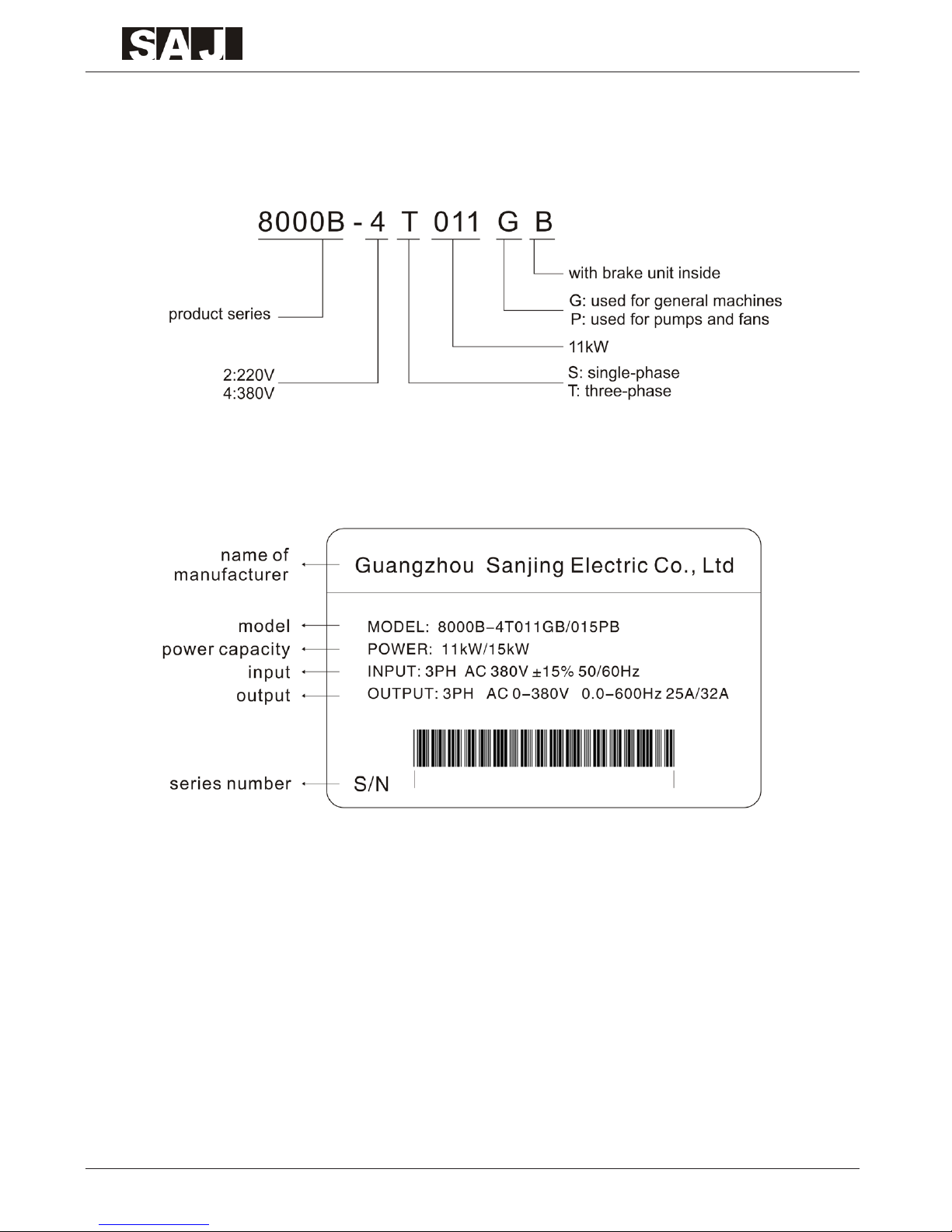
1.1 Description of Model
1.2 Description of Nameplate
-09-
8000B Series
1.3 8000B Series Inverter Table
Inverter Model
G/P
Power
capacity
kW
Rated Input
Current
A
Rated Output
Current
A
Motor
Capacity
kW G/P
Single-phase 220V±15%
8000B-2SR75GB 0.75 8.2 4.5 0.75
8000B-2S1R5GB 1.5 14.2 7 1.5
8000B-2S2R2GB 2.2 23 10 2.2
Three-phase 380V±15%
8000B-4TR75GB 0.75 3.4 2.5 0.75
8000B-4T1R5GB 1.5 5 3.7 1.5
8000B-4T2R2GB 2.2 5.8 5.0 2.2
8000B-4T004GB/4T5R5PB 4/5.5 10/15 9/13 4/5.5
8000B-4T5R5GB/4T7R5PB 5.5/7.5 15/20 13/17 5.5/7.5
8000B-4T7R5GB 7.5 20 17 7.5
8000B-4T011GB/4T015PB 11/15 26/35 25/32 11/15
8000B-4T015GB/4T18R5PB 15/18.5 35/38 32/37 15/18.5
8000B-4T18R5GB 18.5 38 37 18.5
8000B-4T022G/4T030P 22/30 46/62 45/60 22/30
8000B-4T030G/4T037P 30/37 62/76 60/75 30/37
8000B-4T037G 37 76 75 37
8000B-4T045G/4T055P 45/55 90/105 90/110 45/55
8000B-4T055G/4T075P 55/75 105/140 110/150 55/75
8000B-4T075G/4T093P 75/93 140/160 150/176 75/93
8000B-4T093G/4T110P 93/110 160/210 176/210 93/110
8000B-4T110G 110 210 210 110
8000B-4T132G/4T160P 132/160 240/290 250/300 132/160
8000B-4T160G/4T185P 160/185 290/330 300/340 160/185
8000B-4T185G 185 330 340 185
8000B-4T200G/4T220P 200/220 370/410 380/415 200/220
8000B-4T220G/4T250P 220/250 410/460 415/470 220/250
8000B-4T250G/4T280P 250/280 460/500 470/520 250/280
8000B-4T280G/4T315P 280/315 500/580 520/600 280/315
8000B-4T315G 315 580 600 315
8000B-4T350G 350 620 640 350
8000B-4T400G 400 670 690 400

-10-
8000B Series
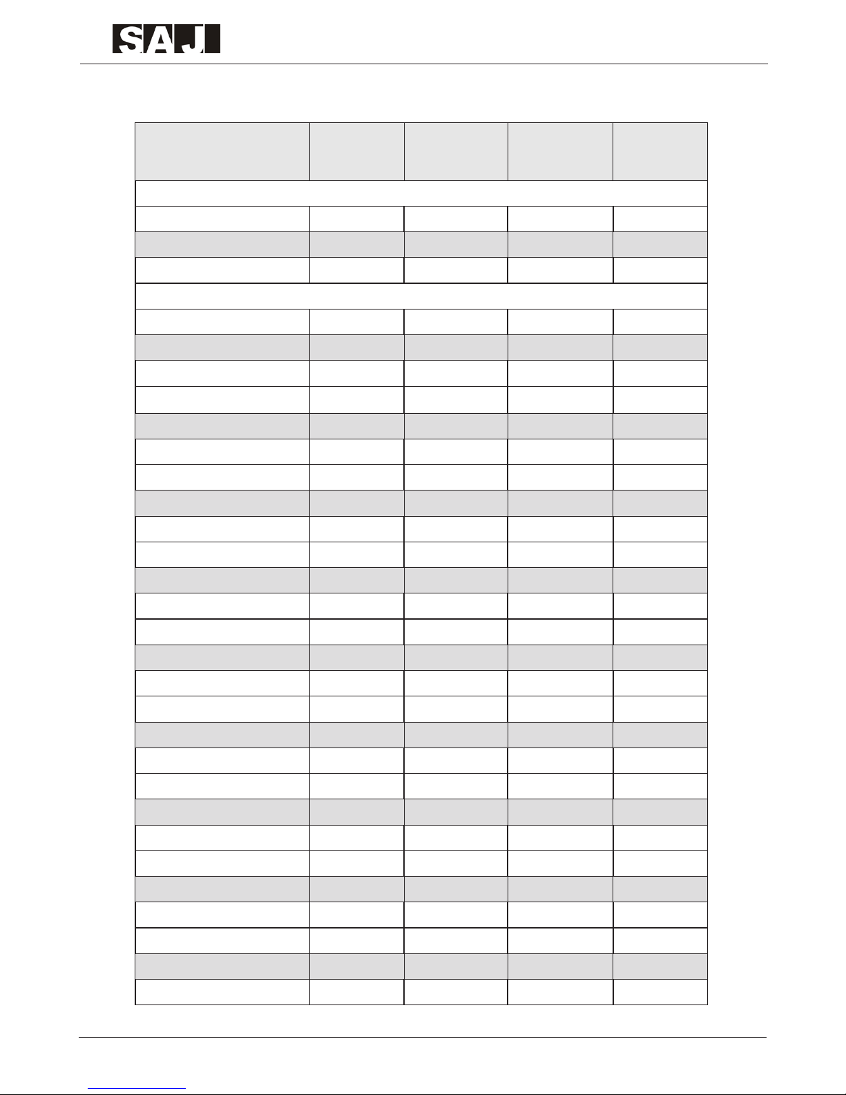
1.4 Specications of 8000B Series Inverter
Characteristics
of Controlling
Control Mode Sensorless vector control V/F control
Start Torque 0.5Hz 150% 0.5Hz 100%
Rotation Speed
Ratio
1:200 1:100
Precision
of Speed
Regulation
±0.5% ±1.0%
Overload
Capability
M od el G: 1 50 % ab ov e th e ra te d cu rr e n t fo r 6 0
seconds;180% above the rated current for one second.
M od e l P : 12 0% a b o v e t h e r a t ed c ur r e n t fo r 60
seconds;150% above the rated current for one second.
V/F curve
Three se l e c ti o n type: Line a r type,Squar e type an d
Multipoint type.
DC Brake
DC brake frequency:0.00~max. frequency;
brake time:0.1~50.0s;
Br a k e c u rren t :0 ~15 0 % of rate d cu rr en t(m o de l G) ;
0~10 0% of rated current:model P);
Brake waiting time:0.0~50.0s
Jog Operation
Jog frequency range:0.00 -max.frequency;
Accel./Decel. time of jog operation:0.1~3600s.
Accel./Decel.
Time
Accel./Decel. time range:0.1~3600s
Torque
Boosting
Manual setting:0.1~30.0%; Automatic setting:0.0
I/O
Characteristics
Start
Frequency
0.50~10Hz
Input Voltage 220V/380V ± 15%
Input
Frequency
50/60Hz,fluctuation range:±5%

-11-
8000B Series
I/O
Characteristics
Input
Frequency
Resolution
Analog setting:max. frequency × 0.1%;
Digital setting:0.01Hz
Output Voltage 0~rated input voltage
Output
Frequency
Range
0.00~600Hz
Digital Input
Terminals
Six (programmable)
Analog Input
Terminals
AVI:0 ~10V; ACI:0~10V or 0/4~20mA
Relay Output 1 relay output
Open Collector
Output
Provide 1 channel programmable
Analog Output
0.75~2.2kW:FM:0~10V; AM:0/4~20mA
4~400kW:FM:0~10V; AM:0~10V / 0/4 -20mA
Basic
Functions
Frequency
Setting
Channels
Three channels:setting by keyboard, set ting by control
terminals, setting by serial communicat ion inter face.
These channels can be switched.
Frequency
Setting Source
8 methods including panel knob setting, UP/DOWN key
setting and PID setting, etc.
Simple PLC
Function
16 steps speed control can be carried out by simple PLC
function inside and terminals.
PID Function
Close-loop controlling system can be carried out by PID
inside.
Swing
Frequency
Function
Suit a b l e fo r te x ti l e and chemi c al fibe r mach i n e by
controlling the triangular frequency.
AVR Function
Automatically keep the output voltage constant when
power supply is not stable.
-12-
8000B Series
Other
Functions
LED Display
16 par a m e t er s ca n by dis p l ayed in cl u d in g run n i n g
freq u e nc y, DC bus vo l t ag e , out p u t volt a g e, ou tp u t
current, etc.
Communication
Function
RS485 with standard MOBUS protocol.
Password
Setting
Four-digit password can be set and beco me effe ctive
after 1 minute.
Parameter Lock
Function
This function can be used to lock the parameter when
running or stop in order to avoid wrong operation.
Fault Protection
Function
O v er - c u r r en t, ov e r v ol ta ge , un d e r - vo lt ag e , o v er
temperature, lack of phase, etc.
Application
Environment
Location
Indoor away from sunlight, dust, corrosive gas, oil fog,
water drop, steam.
Elevation 1000m or less
Ambient
Temperature
-10℃~+40
℃
Humidity 95% RH or less
Vibration < 5.9 m/s2 (0.6G)
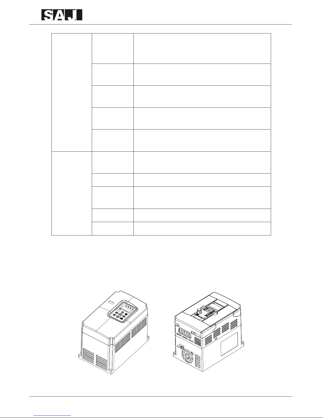
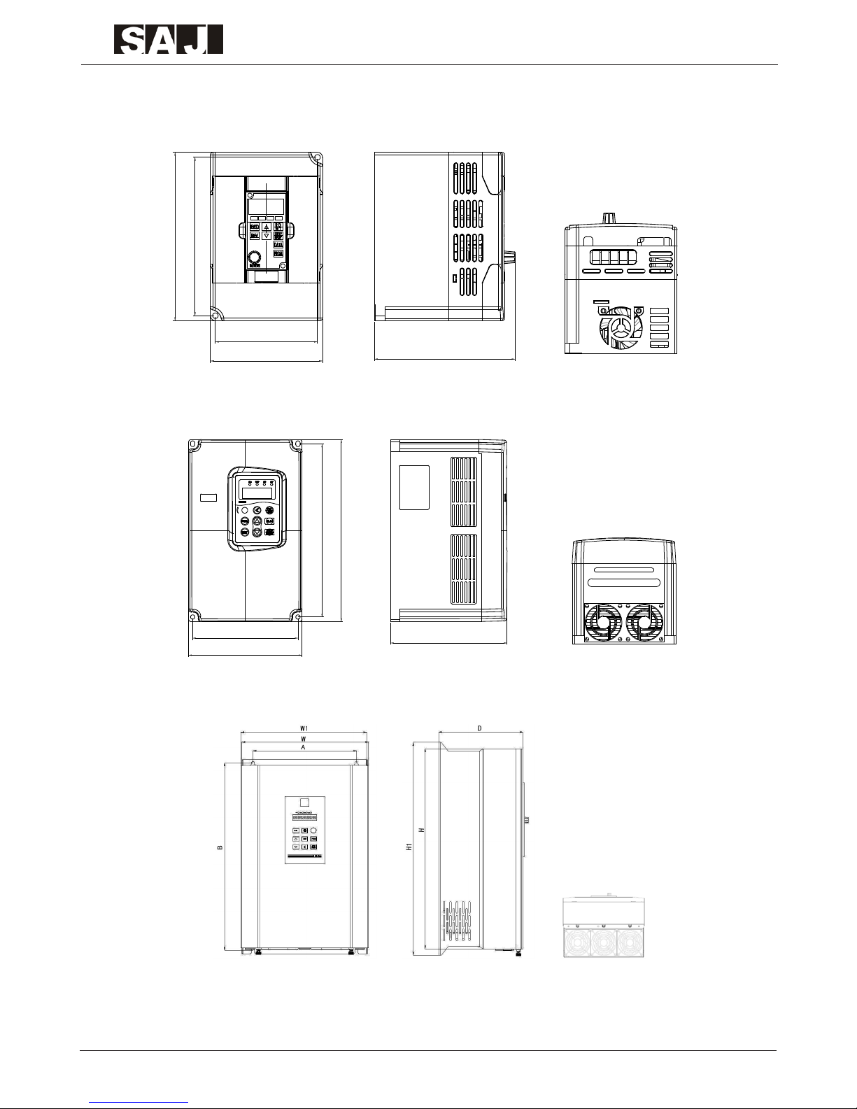
1.5 Outline Drawing and Dimensions
1.5.1 Outline Drawing
-13-
8000B Series
1.5.2 Dimensions
1.5.2.1 Dimensions Drawing
W
A
B
H
D
D
W
A
B
D
0.75kW~2.2kW (model G)
A
W
B
H
D
A
W
B
H
D
4kW~7.5kW (model G)
11kW~110kW (model G)

-14-
8000B Series
132kW~185kW (model G)
200kW~250kW (model G)
280kW~400kW (model G)

-15-
8000B Series
1.5.2.2 Dimensions Table
Inverter Model
Installation
Dimensions
(mm)
Appearance Dimensions (mm)
Hole
Diameter
(mm)
A B H H1 W W1 D
8000B-2SR75GB
92 142.7 151.7 101 126.8 ø58000B-2S1R5GB
8000B-2S2R2GB
8000B-4TR75GB
92 142.7 151.7 101 126.8 ø58000B-4T1R5GB
8000B-4T2R2GB
8000B-4T004GB/4T5R5PB
144.4 237 249.5 155.5 159.5 ø5.98000B-4T5R5GB/4T7R5PB
8000B-4T7R5GB
8000B-4T011GB/4T015PB
156.6 378.3 364 396 214 221.7 190.5 ø68000B - 4T015GB/4T18R5PB
8000B-4T18R5GB
8000B-4T022G/4T030P
235 447 424 463 285 289.6 210.3 ø780 00B - 4T030G/4T037P
8000B-4T037G
8000B-4T045G/4T055P
260 580 544 595.5 380 390 284.8 ø10
8000B-4T055G/4T075P
8000B-4T075G/4T093P
343 674 650 701.5 473 485 318 ø108000B-4T093G/4T110P
8000B-4T110G
8000B-4T132G/4T160P
449 902.5 927 1359 580 384 ø108000B - 4T160G/4T185P
8000B-4T185G
8000B-4T200G/4T220P
420 1162 1131.5 1481.6 680 400.5 ø128000B-4T220G/4T250P
8000B-4T250G/4T280P
8000B-4T280G/4T315P
520 1300 1355 1765 800 392.5 ø14
8000B-4T315G
8000B-4T350G
8000B-4T400G
-16-
8000B Series
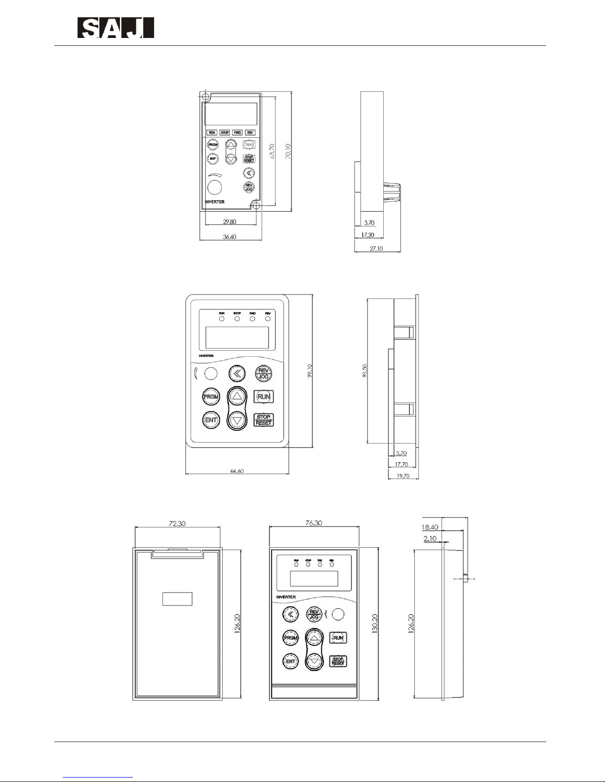
1.5.2.3 Dimensions of Extension Keyboard
0.75kW~2.2kW (model G)
4kW~7.5kW (model G)
11kW~400kW (model G)

-17-
8000B Series
1.6 Selection Instruction Table of Brake Resistor and Brake Unit
Inverter Model
Recommended
Power of Brake
Resistor
Recommended
Resistance Value
of Brake Resistor
Brake Unit
8000B-2SR75GB 80W ≥150Ω
Standard
Accessory
Inside
8000B-2S1R5GB 100W ≥100Ω
8000B-2S2R2GB 100W ≥70Ω
8000B-4TR75GB 150W ≥300Ω
8000B-4T1R5GB 150W ≥220Ω
8000B-4T2R2GB 250W ≥200Ω
8000B-4T004GB/4T5R5PB 300W ≥130Ω
8000B-4T5R5GB/4T7R5PB 400W ≥90Ω
8000B-4T7R5GB 500W ≥65Ω
8000B-4T011GB/4T015PB 800W ≥43Ω
8000B-4T015GB/4T18R5PB 1000W ≥32Ω
8000B-4T18R5GB 1300W ≥25Ω
8000B-4T022G/4T030P 1500W ≥22Ω
Additional
Accessory
(external)
8000B-4T030G/4T037P 2500W ≥16Ω
8000B-4T037G 3.7 kW ≥16.0Ω
8000B-4T045G/4T055P 4.5 kW ≥16Ω
8000B-4T055G/4T075P 5.5 kW ≥8Ω
8000B-4T075G/4T093P 7.5 kW ≥8Ω
8000B-4T093G/4T110P 4.5 kW×2 ≥8Ω×2
8000B-4T110G 5.5 kW×2 ≥8Ω×2
8000B-4T132G/4T160P 6.5 kW×2 ≥8Ω×2
8000B-4T160G/4T185P 16kW ≥2.5Ω
8000B-4T185G 20 kW ≥2.5Ω
8000B-4T200G/4T220P 20 kW ≥2.5Ω
8000B-4T220G/4T250P 22 kW ≥2.5Ω
8000B-4T250G/4T280P 12.5 kW×2 ≥2.5Ω×2
8000B-4T280G/4T315P 14kW×2 ≥2.5Ω×2
8000B-4T315G 16kW×2 ≥2.5Ω×2
8000B-4T350G 17kW×2 ≥2.5Ω×2
8000B-4T400G 14 kW×3 ≥2.5Ω×3
-18-
8000B Series
Chapter 2 Mechanical and Electric Installation
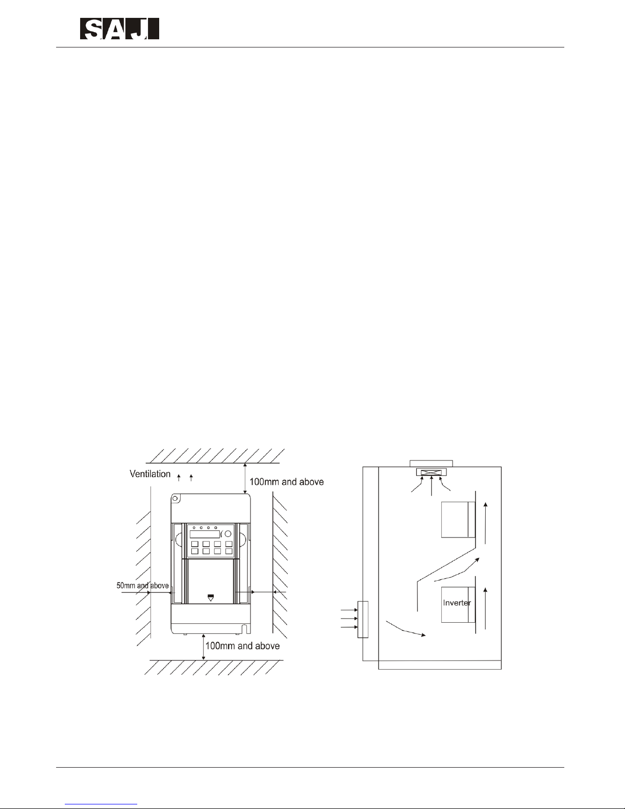
2.1 Mechanical Installation
2.1.1 Installation Environment
The ambient temperature exerts great influences on the service life of the
inverter and is not allowed to exceed the allowable temperature range
(-10℃to 40℃).
The inverter should be mounted on the surface of incombustible articles, with
sufficient spaces nearby for heat sinking. The inverter is easy to generate
large amount of heat during operation. The inverter should be mounted
vertically on the base with screws.
The inverter should be mounted in the place without vibration or with vibration
of less than 0.6G
The inverter should be mounted in locations away from direct sunlight, high
humidity, condensate, corrosive gas, explosive gas, oil dirt, dust, and metal
powder etc.
2.1.2 Installation Space and Distance
When take up-down installation, air deector should be installed between
upper inverter and lower inverter.

-19-
8000B Series
2.1.3 Drawing of Moving the Front Cover
2.2 Electric Installation
2.2.1 Connecting of Peripheral Equipments

-20-
8000B Series
2.2.2 Recommended Table of External Electrical Parts
Inverter Model
Circuit
Breaker
(MCCB)
(A)
Recommended
Contactor (A)
Conducting
Wire of
Main Circuit
at the Input
Side (mm2)
Conducting
Wire of
Main Circuit
at the Input
Side (mm2)
Conducting
Wire of
Control
Circuit
(mm2)
8000 B-2SR75GB 16 10 2.5 2.5 1.0
8000 B-2S1R5GB 20 16 4.0 2.5 1.0
8000 B-2S2R2GB 32 20 6.0 4.0 1.0
8000 B-4TR75GB 10 10 2.5 2.5 1.0
8000 B-4T1R5G B 16 10 2.5 2.5 1.0
8000 B-4T2R2GB 16 10 2.5 2.5 1.0
8000 B-4T004GB/4T5R5PB 25 16 4.0 4.0 1.0
8000 B-4T5R5GB/4T7R5PB 32 25 4.0 4.0 1.0
8000 B-4T7R5GB 40 32 4.0 4.0 1.0
8000 B-4T011GB/4T015PB 63 40 4.0 4.0 1.0
8000 B-4T015GB/4T18R5PB 63 40 6.0 6.0 1.0
8000 B-4T18R5GB 100 63 6.0 6.0 1.5
8000 B-4T022G/4T030P 100 63 10 10 1.5
8000 B-4T030G/4T037P 125 100 16 10 1.5
8000 B-4T037G 160 100 16 16 1.5
8000 B-4T045G/4T055P 200 125 25 25 1.5
8000 B-4T055G/4T075P 200 125 35 25 1.5
8000 B-4T075G/4T093P 250 160 50 35 1.5
8000 B-4T093G/4T110P 250 160 70 35 1.5
8000 B-4T110G 350 350 120 120 1.5
8000 B-4T132G/4T160 P 40 0 400 150 150 1.5
8000 B-4T160G/4T185P 50 0 400 185 185 1.5
8000 B-4T185G 600 600 150*2 150*2 1.5
8000 B-4T200G/4T220P 600 600 150*2 150*2 1.5
8000 B-4T220G/4T250P 600 600 150*2 150*2 1.5
8000 B-4T250G/4T280P 800 600 185*2 185*2 1.5
8000 B-4T280G/4T315P 800 800 185*2 185*2 1.5
8000 B-4T315G 800 800 150*3 150*3 1.5
8000 B-4T350G 800 800 150*4 150*4 1.5
8000 B-4T400G 100 0 1000 150* 150*4 1.5

-21-
8000B Series
2.2.3 Recommended Table of Reactor
Inverter Model
AC Reactor at the
Input Side
AC Reactor at the
output Side
DC Reactor
Voltage
Current
(A)
Inductance
(mH)
Current
(A)
Inductance
(mH)
Current
(A)
Inductance
(mH)
8000 B-2SR75GB 2 7 2 7 3 28
220V8000 B-2S1R5GB 5 3.8 5 3.8 6 11
8000 B-2S2R2GB 7.5 2.5 7.5 2.5 6 11
8000 B-4TR75GB 2 7 2 3 3 28
380V
8000 B-4T1R5G B 5 3.8 5 1.5 6 11
8000 B-4T2R2GB 7 2.5 7 1 6 11
8000 B-4T004GB/4T5R5PB 10 1.5 10 0.6 12 6.3
8000 B-4T5R5GB/4T7R5PB 15 1.0 15 0.25 23 3.6
8000 B-4T7R5GB 20 0.75 20 0.13 23 3.6
8000 B-4T011GB/4T015PB 3 0 0.60 30 0.087 33 2
8000 B-4T015GB/4T18R5PB 40 0.42 40 0.066 33 2
8000 B-4T18R5GB 50 0.35 50 0.052 40 1.3
8000 B-4T022G/4T030P 60 0.28 60 0.045 50 1.08
8000 B-4T030G/4T037P 80 0.19 80 0.032 65 0.80
8000 B-4T037G 90 0.16 90 0.030 78 0.70
8000 B-4T045G/4T055P 120 0.13 120 0.023 95 0.5 4
8000 B-4T055G/4T075P 150 0.10 150 0.019 115 0.45
8000 B-4T075G/4T093P 200 0.08 200 0.014 160 0.36
8000 B-4T093G/4T110P 250 0.0 6 250 0.011 180 0.33
8000 B-4T110G 250 0.06 250 0.011 250 0.26
8000 B-4T132G/4T160 P 290 0.0 4 290 0.008 250 0.26
8000 B-4T160G/4T185P 330 0.0 4 330 0.008 340 0.18
8000 B-4T185G 400 0.04 400 0.005 460 0.12
8000 B-4T200G/4T220P 49 0 0.03 490 0.004 460 0.12
8000 B-4T220G/4T250P 490 0.03 490 0.004 460 0.12
8000 B-4T250G/4T280P 530 0.03 530 0.0 03 650 0.11
8000 B-4T280G/4T315P 60 0 0.02 600 0.003 650 0.11
8000 B-4T315G 660 0.02 660 0.0 02 800 0.06
8000 B-4T350G 400*2 0.04 400*2 0.005 460*2 0.12
8000 B-4T400G 490*2 0.03 490*2 0.004 460*2 0.12

-22-
8000B Series
2.2.4 Descriptions of External Electrical Parts
Name Mounting Location Function
Circuit
Breaker
Front end of input circuit
Disconnect the power supply when the back ward
equipment is over current.
Contactor
Between the circuit
breaker and inverter
input side
Po w er ON / OFF of in ve rt er . Do not us e th e
contactor as the switch of inver ter. Otherwise, it
may cause damage to the inverter.
AC Reactor
at the Input
Side
Input side of inverter
1. Improve the power factor of the input side.
2. Eliminate the harmonic wave at the input side
effec t i v e l y and pr event ot h e r equipment fr o m
damage.
3. Eliminate the input current unbalance caused by
unbalance bet ween the power phases.
EMC Input
Filter
Input side of inverter
1. Reduc e the ex ternal conduction and radiation
interference of inverter.
2. Decrease the conduction inter ference flowing
from the power end to the inverter and improve the
anti-interference capacity of the inverter.
DC Reactor
Additional parts of
8000B series inverter
1. Improve the power factor at the input side.
2. Im pr o v e th e wh o le ef f ic ie nc y and the r ma l
stability of the inverter.
3. Eliminate the impact of higher harmonics at the
input side on the inverter and reduce the external
conduction and radiation interference.
AC Reactor
at the
Output Side
Between inver ter output
side and motor. Close to
inverter.
The inve r te r ou t p u t si de genera l ly ha s hi g h e r
harmonic s. When the motor is far from inverter,
since there are many distributed capacitors in the
circuit, certain harmonics may cause resonance in
the circuit and bring the following t wo impacts:
1. Degrade the motor insulation performance and
damage the motor when running for long time.
2. Gener ate la r g e leakage cur r e n t and cause
frequent inver ter protection.
Generally, installation of output AC reactor is
recommended when the distance between inverter
and motor exceeds 50m.

-23-
8000B Series
Chapter 3 Wiring
3.1 Standard Wiring Diagram
3.1.1 Wiring Diagram of 0.75kW~2.2kW (model G) (3-phase,380V)
Note:
1. ◎ refers to terminals of main circuit; ○ refers to terminals of control circuit.
2. 0.75kW~2.2kW (model G) : brake unit is standard part inside.
3. 0.75kW~2.2kW (model G) of single-phase/220V: main circuit terminals are
R and T.

-24-
8000B Series
3.1.2 Wiring Diagram of 4kW~7.5kW (model G) (3-phase,380V)
Note:
1. ◎refers to terminals of main circuit; ○refers to terminals of control circuit.
2. 4kW~7.5kW (model G) : brake unit is standard part inside.

3.1.3 Wiring Diagram of 11kW~18.5kW (model G) (3-phase,380V)
Note:
1. ◎refers to terminals of main circuit; ○ refers to terminals of control circuit.
2. 11kW~18.5kW (model G) : brake unit is standard part inside.

-26-
8000B Series
3.1.4 Wiring Diagram of 22kW~400kW (model G) (3-phase,380V)
Note:
1. ◎refers to terminals of main circuit; ○ refers to terminals of control circuit.
2. 22kW~400kW (model G) : brake unit is additional part outside.
3. 22kW~400kW (model G) : DC reactor is additional part outside.

-27-
8000B Series
3.2 Terminal Descriptions of Main Circuit and Control Circuit
3.2.1 Main Circuit Terminals:
(1) Main circuit terminals (0.75kW~2.2kW (model G) with built-in brake unit)
(2) Main circuit terminals (4kW~7.5kW (model G) with built-in brake unit)
(3) Main circuit terminals (11kW~18.5kW (model G) with built-in brake unit)
(4) Main circuit terminals (22kW~37kW (model G))
(5) Main circuit terminals (45kW~110kW (model G))
(6) Main circuit terminals (132kW~400kW (model G))

-28-
8000B Series
Terminals Descriptions
R, S, T Terminals of AC power input.
U,V, W Terminals of AC power output
(+), (-) Spare terminals for connecting external brake unit.
P Spare terminal for connecting external DC reactor.
PB Spare terminal for connecting external brake resistor.
Grounding terminal
3.2.2 Precautions on Main Circuit Wiring
3.2.2.1 Terminals R, S and T
The wiring at the input side of inverter has no phase sequence requirement.
When input single-phase power, use terminal R and T.
3.2.2.2 DC Bus Terminals (+) and (-)
The (+) and (-) terminals of DC bus have residual voltage right after power-off.
Wait until the CHARGE indicator is OFF and make sure that the voltage is less
than 36V before wiring. Otherwise it may cause electrical shock.
When use external brake unit for inverter of 22kW and above, the poles of (+)
and (-) should not be connected reversely. Otherwise, it may cause damage to
inverter and even cause re.
The cable length of brake unit should be less than 10m. Use twisted pair cable
or connect in parallel.
Do not connect brake resistor directly to the DC bus. Otherwise, it may cause
damage to inverter and even cause re.
3.2.2.3 Terminals (+) and PB of Brake Resistor
The terminals of brake resistor are effective only for inverter of 18.5kW and
below with built-in brake unit.
The cable length of brake resistor should be less than 5m.
3.2.2.4 Terminals P and (+) of External Reactor
For inverter of 22kW and above, the reactor is additional part which is
connected externally.

3.2.2.5 Terminals U, V and W
Capacitor device or surge absorber can not be connected to inverter output
side by terminals U, V and W. Otherwise, it may cause frequent inverter
protection or damage to inverter.
If motor cable is too long, it may generate electrical resonance easily due to
the impact of distributed capacitance and thus damage the motor insulation or
generate higher leakage current to cause inverter protection. When the length
of motor cable is longer than 50m, installing AC reactor at the output side is
necessary.
3.2.2.6 Grounding Terminal
The terminal should be grounded reliably. The resistance value of
grounding cable should be less than 10Ω. Otherwise, it may cause fault or
damage to the inverter.
Do not share the grounding terminal with zero line of power supply.
3.2.3 Control Circuit Terminals
0.75kW~2.2kW Control Circuit Terminals
TA TB TC M1 M2 M3 M4 M5 M6 GND FM AM ACI 10V AVI GND MCM MO1
4kW~400kW Control Circuit Terminals
Communication Terminals
1 2 3 4 5 6 7 8
S+ S- +15V GND +5V NC +5V GND

-30-
8000B Series
Type
Terminal
Symbol
Function
Interface
Standard
Computer
Communication
S+ 485 difference signal positive terminal
Standard RS485
communication
interface
S- 485 difference signal negative terminal
+5V Extension power positive terminal (+5V)
+15V Extension power positive terminal(+15V)
GND Extension power negative terminal
3.2.4 Descriptions of Control Circuit Terminals
Symbol Terminal Name Function
M1~M6
Multi-function
digital input
terminal
0.75-2.2kW (G): Digital terminals can not be connected
to power directly.
When connected to GND terminal, it is power-on and
the corresponding current is 10mA.
4kW and above: Opt i ca l cou p li n g iso l a ti o n inp u t
compatible with +24V and COM.
Input voltage range:9-36V, input impedance:3.3kΩ
MO1
Multi-function
output terminal
(optical coupling isolating)Max. DC 48V/50mA
MCM
Common terminal
of multi-function
output terminal
(optical coupling isolating)Max. DC 48V/50mA
AVI
Analog input
terminal 1
Input voltage range:DC 0~10V (input impedance:20kΩ)
ACI
Analog input
terminal 2
1. input range:DC 0-10V or 0/4~20mA . It is selected
by jumper JP1 on control board. The default is current
input. 1-2Pin: voltage input; 2-3Pin: current input.
2. Input impedance:20kΩ when input voltage; 500Ω
when input current.
10V
Analog reference
voltage
10V ±5%,max. current: 30mA
GND
Analog grounding
terminal
Zero potential referring to +10V
FM
Analog output
terminal 1
FM:0 ~10V

-31-
8000B Series
AM
Analog output
terminal 2
Output range: 0 ~10V or 0/4 -20mA. It is selected by
jumper JP2 on control board. The default is current
output.
1-2Pin: current output; 2-3Pin: voltage output.
0.75~2.2kW:0/4~20mA .
4~400kW:0~10V / 0/4~20mA .
TA/TB/
TC
Relay output
contact
TA-TB:normal open;TB-TC:normal close
Contact capacity:
AC 250V / 3A/ normal open
AC 250V / 3A / normal close
+24V
+24V power
supply
Output current: Maxi. 200mA,usually used as power of
digital input /output terminals and external sensor.
COM
+24V power
supply
Output current: Maxi. 200mA,usually used as power of
digital input /output terminals and external sensor.
3.2.5 Precautions for Connecting Control Circuit Terminals
It is necessary to use shielded cable and twisted pair cable with well-grounded
(inverter side). The cable length should be more than 20cm away from main
circuit and strong electricity circuit. In order to avoid interference which can
cause inverter fault, use vertical connection instead of parallel connection.

-32-
8000B Series
Chapter 4 Operation
4.1 Keypad Description
4.1.1 Keypad Schematic Diagram
4.1.2 Key Function Description
Symbol Key Name Function Description
PRGM Program/ Exit key Enter or exit of menu, parameter modification
ENT Data enter key
P ro g r e ss i ve ly e nt er m en u a n d c on f ir m
parameter.
UP increase key Progressively increase data or function codes.
DOWN decrease key Progressively decrease data or function codes.
≤ Shift key
Use it to select displayed parameters cyclically
du r ing running or stop statu s . In pa r ameter
setting mode, press this key to select the bit to
be modified.
RUN Run key Start to run the inverter in keypad control mode.
STOP/
RESET
Stop/reset key
In running status, restricted by function code
F7.04, it can be used to stop the inver ter,
In malfunction alarm status, not restricted by
function code F7.04, it can be used to reset the
inverter.
REV/JOG Shortcut key Determined by function code F7.03.

-33-
8000B Series
4.1.3 Indicator Light Description
Indicator Light Name Description
RUN Light on: inverter running status.
STOP Light on: inverter stops or malfunction status.
FWD
Lights of FWD and RUN are on at the same time: inverter
for ward running status.
REV
Lights of REV and RUN are on at the same time: inverter
reversely running status.
4.2 Operation Process
4.2.1 Parameter Setting
Three levels of menu are as following:
·Function code group (rst-class)
·Function code (second-class)
·Setting parameter of function code (third-class)
Remarks:
Pressing PRGM or ENT can return to the second-class menu from the thirdclass menu. The difference is: Pressing ENT will save the setting parameters
into control board, and return to the second-class menu with shifting to the
next function code automatically. While pressing PRGM will directly return to
the second-class menu without saving the parameters, and keep staying at
the current function code.
For example: change the parameter 00.50Hz of function code F1.01 into
05.00Hz as the following ow chart shows:
Flow Chart of Parameter Setting

-34-
8000B Series
Under the third-class menu, if the parameter has no ickering bit, it means that
the function code cannot be modied. The possible reasons include:
(1) The parameter of this function code can’t be modified, such as actually
detected parameter, operation records and so on.
(2) This function code can’t be modified during running status, but can be
modied during stop status.
4.2.2 Fault Reset
When inverter malfunction occurs, it will display the relative fault information.
Use the STOP/ RESET key or terminals (determined by F5 group) to reset the
fault. After fault reset, inverter is at stand-by status. If not reset when inverter
is at fault status, it will keep operation protection status and cannot run.
4.2.3 Motor Parameter Autotuning
When select SVC control mode (sensorless vector control), make sure that
motor nameplate parameters are correctly input into the inverter. Inverter will
match standard motor parameter according to nameplate parameter. In order
to achieve precise control, autotuning is necessary. Refer to the following
steps:
Firstly, set the parameter of F0.01 to 0. This means that select the keypad
to control stop or start. Then input the following parameters according to the
motor nameplate:
F2.01: Motor rated power
F2.02: Motor rated frequency
F2.03: Motor rated rotation speed
F2.04: Motor rated voltage
F2.05: Motor rated current
Remarks:
If motor can be uncoupled with its load completely, set the parameter of
F2.11 to 1 (complete tuning) and then push RUN key, inverter can calculate
the parameter of motor. During autotuning process, the panel of inverter will
display –RUN-. When it displays –END-, the autotuning process is nished.
If motor cannot be uncoupled with its load, set the parameter of F2.11 to 2
(static tuning) and push RUN key, inverter will auto-detect the parameters

-35-
8000B Series
of motor stator resistor, rotator resistor and leakage inductance, while the
parameters of motor mutual inductance and no-load current are not detected.
The parameters of motor mutual inductance and no-load current can be
calculated by the following formula:
IO:motor no-load current
Lm: motor mutual inductance
Lδ: motor leakage inductance
U: motor rated voltage
I: motor rated current
f: motor rated frequency
η: motor power factor
4.2.4 Password Setting
When F7.00 is set to be non-zero, the parameter will be the user’s password.
After exit the function code editing status, the password will be effective after
one minute. And then press the PRGM key again to try to access the function
code editing mode, the inverter panel will display “0.0.0.0”. The password
must be input correctly to access it. If it is necessary to cancel the password
function, set F7.00 to zero.
Notice:
When the inverter is powered on, system will execute initialization first and
inverter panel displays “8000” with four lights on. After initialization, inverter
accesses into stand-by status.

-36-
8000B Series
Chapter 5 Function Code Table
Notice:
“○”:
The parameters can be modied at stop or running status.
“◎”:
The parameters cannot be modied at running status.
“●”:
The parameters which are actual-detecting record value cannot be modied.
Function
Code
Function Descriptions
Minimum
Unit
Factory
Setting
Modi-
cation
Type
F0 Group: Basic Parameters
F0.00
Control mode
selection
0: Sensorless vector control
1:V/F control
1
●
F0.01
Run command
source
0:Keypad
1:Terminals
2: Communications (RS485)
0
●
F0.02
Setting value
valid or not
of keypad /
terminals
0: Valid and saved when poweroff
1: Va l id an d n o t sav e d w h en
power-off
2: Invalid
3 . Va l id a t ru nn i n g s t a tu s .
Changed into the set ting value
of F0.08 when restart after stop.
0
○
F0.03
Master
frequency
setting source X
0: Up/down key
1: Potentiometer of panel
2: AVI terminal
3: ACI terminal
4: Reserved
5: Reserved
6: Mu l t i- fu nc t io n digit a l inpu t
terminals
7: PLC
8: PID
9: Communication inter face
1
●
F0.04
Auxiliary
frequency
setting source Y
0: AVI terminal
1: ACI terminal
2: Reser ved
1
●

-37-
8000B Series
Function
Code
Function Descriptions
Minimum
Unit
Factory
Setting
Modi-
cation
Type
F0.05
Range of
auxiliary
frequency
setting source Y
0 : R e l a t i v e t o t h e m a x i .
frequency
1: Relative to master frequency
setting source X
0
●
F0.06 Reserved
F0.07
Frequency
setting source
selection
0:X
1: Y
2: X and Y
3: Max. value of (X, Y)
0
○
F0.08
Keypad setting
frequency
0.00Hz~ F0.10 0.01Hz 50.00 Hz
○
F0.09
Running
direction
selection
0: Forward
1: Reverse
2: Reverse running prohibited
0
●
F0.10
Max. output
frequency
10.00~600.00Hz 0.01Hz 50.00Hz
●
F0.11
Upper limit
frequency
setting source
0:Keypad (F0.12)
1:AVI terminal
2: ACI terminal
3: Mu l t i- fu nc t io n digit a l inpu t
terminals
4: Communication interface
0
○
F0.12
Upper limit
of running
frequency
F0.14~ F0.10 0.01Hz 50.00Hz
○
F0.13 Reserved
F0.14
Lower limit
of running
frequency
0.00Hz~ F0.12 0.01Hz 0.00Hz
○

-38-
8000B Series
Function
Code
Function Descriptions
Minimum
Unit
Factory
Setting
Modi-
cation
Type
F0.15
The function
of lower limit
frequency
0 : R u n n i n g a t l o w e r l i m i t
frequency
1: Stop frequency point
2: Sleep frequency point
0
○
F0.16
Carrier
frequency
1.0~15.0kHz 1kHz
Different
according
to the
inverter
type
○
F0.17
PWM mode
selection
0:PWM mode 1
1:PWM mode 2
2:PWM mode 3
0
●
F0.18
Acceleration
time 1
0.1~3600.0s 0.1s
Different
according
to the
inverter
type
○
F0.19
Deceleration
time 1
0.1~3600.0s 0.1s
Different
according
to the
inverter
type s
○
F0.20 Default setting
0:No operation
1: Restore to factory setting
2:Fault record clearing
0
●
F0.21
Parameter lock
setting
0: Unlock parameter
1: Lock parameter
0
○
F0.22
Acceleration/
deceleration
method
0: Linear method
1: Reserved
0
●
F0.23 Reserved
F0.24 Reserved

-39-
8000B Series
Function
Code
Function Descriptions
Minimum
Unit
Factory
Setting
Modi-
cation
Type
F0.25
Cooling fan
running method
(only for 4kW
and above
inverter)
0: Keep running when power on
1: Automatic running
1
○
F1 Group: Star t and Stop Parameters
F1.00 Start mode
0:Start directly
1:DC braking first and then start
2:Speed tracing and star t
0
●
F1.01 Start frequency 0.00~10.00Hz 0.01Hz 1.50Hz
○
F1.02
Hold time of
start frequency
0.0~50.0s 0.1s 0.0s
○
F1.03
DC braking
current before
start
0.0~150.0% 0.1% 0.0%
○
F1.04
DC braking time
before start
0.0~50.0s 0.1s 0.0s
○
F1.05 Stop mode
0: Deceleration to stop
1: Coast to stop
0
○
F1.06
Starting
frequency of DC
braking
0.00~ F0.10 0.01Hz 0.00Hz
○
F1.07
Waiting time
before DC
braking
0.0~50.0s 0.1s 0.0s
○
F1.08
DC braking
current
0.0~150.0% 0.1% 0.0%
○

-40-
8000B Series
Function
Code
Function Descriptions
Minimum
Unit
Factory
Setting
Modi-
cation
Type
F1.09 DC braking time 0.0~50.0s 0.1s 0.0s
○
F1.10
Dead time
between FWD
and REV
0.0~3600.0s 0.1s 0.0s
○
F1.11
Terminals
enable option
when power on
0: Disabled
1: Enabled
1
○
F1.12
~
F1.17
Reserved
F1.18
Wake-up time
delay
0.0~3600s 0.1s 0.0s
○
F1.19
Restart option
after power-off
0: Disabled
1:Enabled
0
○
F1.20
Waiting time of
restart
0.0~3600s 0.1s 0.0s
○
F1.21
Over
modulation
option
0: Disabled
1:Enabled
0
○
F2 Group: Motor Parameters
F2.00 Inverter model
0:General model (G)
1:Pump model (P)
0
●
F2.01
Motor rated
power
0.4~700.0kW 0.1kW
Different
according
to
inverter
model
●
F2.02
Motor rated
frequency
10.00Hz~ F0.10 0.01Hz 50.00Hz
●

-41-
8000B Series
Function
Code
Function Descriptions
Minimum
Unit
Factory
Setting
Modi-
cation
Type
F2.03
Motor rated
rotation speed
0~36000rpm 1rpm
Different
according
to
inverter
model
●
F2.04
Motor rated
voltage
0~480V 1V
●
F2.05
Motor rated
current
0.8~2000A 0.1A
●
F2.06
Motor stator
resistance
0.001~65.53Ω 0.001Ω
○
F2.07
Motor rotator
resistance
0.001~65.53Ω 0.001Ω
○
F2.08
Motor stator
inductance
0.1~6553mH 0.1mH
○
F2.09
Motor rotator
mutual
inductance
0.1~6553mH 0.1mH
○
F2.10
Motor no-load
current
0.1~655.3A A
○
F2.11
Motor
parameters
autotuning
0:No autotuning
1:Autotuning completely(no load)
2:Static autotuning(with load)
0
●
F2.12 Reser ved
F3 Group: Vector Control Parameters
F3.00
Propor tional
gain 1 of speed
loop
0~100 20
○
F3.01
Integral time 1
of speed loop
0.01~10.00s 0.01s 0.50s
○
F3.02
Low frequency
point of switch
0.00Hz~F3.05 0.01Hz 5.00Hz
○

-42-
8000B Series
Function
Code
Function Descriptions
Minimum
Unit
Factory
Setting
Modi-
cation
Type
F3.03
Propor tional
gain 2 of speed
loop
0~100 1 25
○
F3.04
Integral time 2
of speed loop
0.01~10.00s 0.01s 1.00s
○
F3.05
High frequency
point of switch
F3.02~F0.10 1Hz 10.00Hz
○
F3.06
Coefficient
of slip
compensation
at VC control
mode
50~200% 1% 100%
○
F3.07
Upper limit
torque
0 . 0 ~2 0 0 .0 % (i nv e r te r r at e d
current)
0.1% 150.0%
○
F3.08 Reserved
F3.09 Reserved
F3.10
Pre-alarm
option when
overload
0: Not detect
1: Effective during running and
keep running after alarm
2: Ef f e c t i ve d u r in g r u n n i n g
a n d s t o p a f t e r a la r m ( f a ul t
code:E023)
3: Ef fe c ti v e du ri ng co n sta nt
running and keep running after
alarm
4: Ef fe cti ve du ri n g c o nst ant
running and stop after alarm
1
○
F3.11
Detecting level
of pre-alarm
when overload
1.0~200.0% (referred to inverter
rated current)
0.1% 150.0%
○
F3.12
Detecting time
of pre-alarm
when overload
0~ 600s 1s 1s
○

-43-
8000B Series
Function
Code
Function Descriptions
Minimum
Unit
Factory
Setting
Modi-
cation
Type
F4 Group: V/F Control Parameters
F4.00
V/F curve
selection
0: Linear curve
1: User-defined curve
2: 1.3 square torque -step - down
cur ve
3: 1.7 square torque-step-down
cur ve
4: 2 sq uare torque - step- d o w n
cur ve
0
●
F4.01 Torque boost
0.0 %(auto)
0.1%~30.0%
0.1% 1.0%
○
F4.02
Torque
boost cut-off
frequency
0.0 ~50. 0 % (r el at i ve to moto r
rated frequency)
0.1% 20.0%
●
F4.03
V/F frequency
1
0.00Hz~F4.05 0.01Hz 0.00Hz
●
F4.04 V/F voltage 1 0.0%~100.0% 0.1% 0.0%
●
F4.05
V/F frequency
2
F4.03~F4.07 0.01Hz 25.00Hz
●
F4.06 V/F voltage 2 0.0%~100.0% 0.1% 50.0%
●
F4.07
V/F frequency
3
F4.05~motor rated frequency 0.01Hz 50.00Hz
●
F4.08 V/F voltage 3 0.0%~100.0% 0.1% 100.0%
●
F4.09
Coefficient
of V/F Slip
compensation
0.0%~200.0% 0.1% 0.0%
○
F4.10
Energy-saving
selection
0:Disabled
1:Enabled automatically
0
○
F4.11 Reserved

-44-
8000B Series
Function
Code
Function Descriptions
Minimum
Unit
Factory
Setting
Modi-
cation
Type
F4.12
Low-frequency
threshold of
restraining
oscillation
0~10 2
○
F4.13
High-frequency
threshold of
restraining
oscillation
0~10 0
○
F4.14 Reserved
F4.15
Boundary
frequency of
restraining
oscillation
0.00Hz~F0.10 (Maxi. frequency) 0.01Hz 30.00Hz
○
F4.16 Reserved
F4.17
AVR function
selection
0:Invalid
1:Valid all the time
2 : O n l y i n v a l i d d u r i n g
deceleration
1
○
F5 Group: Input Terminals Parameters
F5.00
M1 terminal
function
0:Invalid
1:Forward run (FWD)
2:Reverse run (REV)
3:3-wire control
4:For ward jog run (FJOG)
5:Reverse jog run (RJOG)
6: Coast to stop
7: Fault reset (RESET)
8: Pause running
9: External fault input N. O.
10: UP Key command
11: DOWN Key command
12: Clear UP/DOWN setting
1
●
F5.01
M2 terminal
function
2
●

-45-
8000B Series
Function
Code
Function Descriptions
Minimum
Unit
Factory
Setting
Modi-
cation
Type
F5.02
M3 terminal
function
13: Fre q u e ncy setti n g sour c e
switch between X and Y
14: Freq u e ncy setti n g sou r c e
switch between X and (X+ Y)
15: Fre q u ency sett i n g sour c e
switch between Y and (X+ Y)
16: Multi-step speed terminal 1
17: Multi-step speed terminal 2
18: Multi-step speed terminal 3
19: Multi-step speed terminal 4
20: Multi-step speed pause
21: Ac ce l e rat i o n/de c ele r atio n
time selection terminal 1
22: Ac c ele r a t ion /de c eler a t i on
time selection terminal 2
2 3 : R e se t si mp l e PL C a f t e r
pause
24: Simple PLC pause
25: PID pause
26: Swing frequency pause (stop
at current frequency)
27: Reset after swing frequency
p a u s e ( r e s e t t o c e n t r a l
frequency)
28: Counter reset
29:Reserved
30: Ac cele r at io n/d ec eler at i on
prohibited
31:Counter triggering
3 2 :C le ar UP /D OW N s et ti ng
temporarily
33: Reserved
34: Counting meter input
35: Counting meter clear up
36: Command source switch
37: Terminal input delay output
38: Reserved
7
●
F5.03
M4 terminal
function
0
●
F5.04
M5 terminal
function
0
●
F5.05
M6 terminal
function
0
●

-46-
8000B Series
Function
Code
Function Descriptions
Minimum
Unit
Factory
Setting
Modi-
cation
Type
F5.06
~
F5.09
Reserved
F5.10
On/off filter
times
1~10 5
○
F5.11
FWD/ REV
control mode
0:2-wire control mode 1
2:2-wire control mode 2
3:3- wire control mode 1
4:3- wire control mode 2
0
●
F5.12
Frequency
change rate
when UP/
DOWN setting
0.01~50.00Hz/s 0.01Hz/s 0.50Hz/s
○
F5.13 AVI lower limit 0.00V~10.00V 0.01V 0.00V
○
F5.14
AVI lower limit
corresponding
to setting value
-100.0%~100.0% 0.1% 0.0%
○
F5.15 AVI upper limit 0.00V~10.00V 0.01V 10.00V
○
F5.16
AVI upper limit
corresponding
to setting value
-100.0%~100.0% 0.1% 100.0%
○
F5.17
AVI input filter
time
0.00s~10.00s 0.01s 0.10s
○
F5.18 ACI lower limit 0.0mA~20.0mA 0.1mA 4.0mA
○
F5.19
ACI lower limit
corresponding
to setting value
-100.0%~100.0% 0.1% 0.0%
○
F5.20 ACI upper limit 0.0mA~20.0mA 0.1mA 20.0mA
○

-47-
8000B Series
Function
Code
Function Descriptions
Minimum
Unit
Factory
Setting
Modi-
cation
Type
F5.21
ACI upper limit
corresponding
to setting value
-100.0%~100.0% 0.1% 100.0%
○
F5.22
ACI input filter
time
0.00s~10.00s 0.1s 0.10s
○
F5.23
~
F5.32
Reserved
F6 Group: Output Terminals Parameters
F6.00
MO1 output
selection
0:No output
1:Motor forward running
2:Motor reverse running
3:Fault output
4: Fr eq ue nc y de t ec ting lev e l
FDT output
5:Frequency reached
6:Running at zero speed
7:Upper limit frequency reached
8:Lower limit frequency reached
9:Frequency setting value less
than lower limit frequency
10:FDT reached
11:Acc u m u l ative ru n ning ti m e
reached
12:PLC cycle completed
13:Pre-alarm when overload
14:User define output
15:Running frequency detection
16:Terminal input delay
17:Inverter stand-by
1
○
F6.01 Reserved 0
○
F6.02
Relay 1 output
selection
3
○
F6.03
Relay 2 output
selection
0
○

Function
Code
Function Descriptions
Minimum
Unit
Factory
Setting
Modi-
cation
Type
F6.04
FM output
selection
0:Running frequency
1:Setting frequency
2:Running rotation speed
3:Output current
4:Output voltage
5:Reserved
6:Reserved
7:Reserved
8: Analog AVI input value
9: Analog ACI input value
0
○
F6.05
FM output lower
limit
0.0~100.0% 0.1% 0.0%
○
F6.06
FM lower limit
corresponding
to output
0.00V~10.00V 0.01V 0.00V
○
F6.07
FM output upper
limit
0.0~100.0% 0.1% 100.0%
○
F6.08
FM upper limit
corresponding
to output
0.00V~10.00V 0.01V 10.00V
○
F6.09
AM output
selection
0:Running frequency
1:Setting frequency
2:Running rotation speed
3:Output current
4:Output voltage
5:Reserved
6:Reserved
7:Reserved
8: Analog AVI input value
9: Analog ACI input value
0
○
F6.10
AM output lower
limit
0.0~100.0% 0.1% 0.0%
○
F6.11
AM lower limit
corresponding
to output
0.00V~10.00V 0.01V 0.00V
○

-49-
8000B Series
Function
Code
Function Descriptions
Minimum
Unit
Factory
Setting
Modi-
cation
Type
F6.12
AM output
upper limit
0.0~100.0% 0.1% 100.0%
○
F6.13
AM upper limit
corresponding
to output
0.00V~10.00V 0.01V 10.00V
○
F6.14
User defined
output
variability option
(EX)
0:Running frequency
1:Setting frequency
2:DC bus voltage
3:Output current
4:Output voltage
5:Sign of start and stop status
6:Sign of control status
7:Counter value
8:Counting meter value
9:Inverter module temperature
10:AVI input value
11:ACI input value
0
○
F6.15
Comparison
method of user
defined output
Un its dig it: co m pa r is o n te st
method
0: equal (EX==X1)
1: equal or greater than
2: equal or less than
3 : i n t e r v a l c o m p a r i s o n
(X1≤EX≤X2)
4:units digit test (EX&X1=X2)
Tens digit : output method
0 : false value output
1: real value output
00
○
F6.16
User defined
dead interval
0~ 65535 0
○
F6.17
Output
comparison
value X1
0~ 65535 0
○
F6.18
Output
comparison
value X2
0~ 65535 0
○

-50-
8000B Series
Function
Code
Function Descriptions
Minimum
Unit
Factory
Setting
Modi-
cation
Type
F7 Group: Display Interface Parameters
F7.00 User password 0~9999 0
○
F7.01 Reserved
F7.02 Reserved
F7.03
REV/JOG
key function
selection
0:Switch display status
1:Clear UP/DOWN setting
2:Reverse running
3:For ward jog running
4:Quick debugging mode
2
●
F7.04
Stop function
selection of
STOP/RESET
key
0:Only valid for keypad setting
1:Valid for both keypad set t ing
and terminals setting
2:Valid for both keypad set ting
and com m u ni c at i on inter fa ce
setting
3:Valid for all control mode
0
○
F7.05 Reserved
F7.06
Running
status display
selection 1
0~ 0xFFFF
BIT0:Running frequency
BIT1:Setting frequency
BIT2:DC bus voltage
BIT3:Output voltage
BIT4:Output current
BIT5:Running speed
BIT6:Linear speed
BIT7:Reserved
BIT8:Reser ved
BIT9:PID setting value
BIT10:PID feedback value
BIT11:Input terminals status
BIT12:Output terminals status
BIT13:Reserved
BIT14:Counter value
BIT15:Current step of multi-step
speed and PLC
35
○

-51-
8000B Series
Function
Code
Function Descriptions
Minimum
Unit
Factory
Setting
Modi-
cation
Type
F7.07
Running
status display
selection 2
1~0xFFFF
BIT0:AVI value
BIT1: ACI value
BIT2:Reserved
BIT3: Motor overload ratio
BIT4: Inverter overload ratio
BIT5:Running time
BIT6:Counting meter value
BIT7~BIT15: Reser ved
0
○
F7.08
Stop status
display
selection
0~ 0xFFFF
BIT0: Setting frequency
BIT1: DC bus voltage
BIT2:Input terminal status
BIT3:Output terminal status
BIT4:PID setting value
BIT5:PID feedback value
BIT6:AVI value
BIT7:ACI value
BIT8:Reser ved
BIT9: Current step of multi-step
speed and PLC
BIT10:Reserved
BIT11:Counting meter value
BIT12~BIT15:Reserved
3
○
F7.09
Inverter module
temperature
0~100
℃
1
℃ ◎
F7.10
Inverter
software
version
◎
F7.11
Accumulative
running time
0~9999h 1hour
◎
F7.12
Accumulative
power-on time
0~9999h 1hour
◎
F7.13 Reserved

-52-
8000B Series
Function
Code
Function Descriptions
Minimum
Unit
Factory
Setting
Modi-
cation
Type
F8 Group: Auxiliary Function Parameters
F8.00
Jog running
frequency
0.00~F0.10 0.01Hz 5.00Hz
○
F8.01
Jog running
acceleration
time
0.1~3600s 0.1s
Dened
by
inverter
model
○
F8.02
Jog running
deceleration
time
0.1~3600s 0.1s
○
F8.03
Acceleration
time 2
0.1~3600s 0.1s
○
F8.04
Deceleration
time 2
0.1~3600s 0.1s
○
F8.05
Acceleration
time 3
0.1~3600s 0.1s
○
F8.06
Deceleration
time 3
0.1~3600s 0.1s
○
F8.07
Acceleration
time 4
0.1~3600s 0.1s
○
F8.08
Deceleration
time 4
0.1~3600s 0.1s
○
F8.09
Skip frequency
1
0.00~F0.10 0.01Hz 0.00Hz
○
F8.10
Skip frequency
2
0.00~F0.10 0.01Hz 0.00Hz
○
F8.11
Skip frequency
bandwidth
0.00~F0.10 0.01Hz 0.00Hz
○

-53-
8000B Series
Function
Code
Function Descriptions
Minimum
Unit
Factory
Setting
Modi-
cation
Type
F8.12 FDT level 0.00~F0.10 0.01Hz 50.00Hz
○
F8.13 FDT lag 0.0~100.0% 0.1% 5.0%
○
F8.14
Detecting range
of reached
frequency
0.0~100.0% (Maxi. frequency) 0.1% 0.0%
○
F8.15
Braking
threshold
voltage
115.0 ~140.0% (standard DC bus
voltage)
0.1% 120.0%
○
F8.16
Speed display
coefficient
0.1~999.9% 0.1% 100.0%
○
8.17
Start/stop
selection when
running time is
over
0:Keep running
1:Stop
0
○
F8.18
Running time
setting
0~9999h 1h 9999
○
F8.19 Droop control 0.00Hz~10.00Hz 0.01Hz 0.00Hz
○
F8.20
Panel filter time
selection
0.00~10.00s 0.01s 0.10s
○
F8.21
Output delay
time selection
0~9999s 0.1s 0.0s
○
F8.22
Lower limit
of frequency
detecting
0.00~Maxi. frequency 0.01Hz 20.00Hz
○
F8.23
Upper limit
of frequency
detecting
0.00~Maxi. frequency 0.01Hz 40.00Hz
○
F8.24 Reserved

-54-
8000B Series
Function
Code
Function Descriptions
Minimum
Unit
Factory
Setting
Modi-
cation
Type
F8.25
Inverter rated
power
0.4~700.0kW 0.1kW
Dened
by
inverter
model
◎
F8.26
Inverter rated
current
0.0~2000A 0.1A
◎
F8.27
Linear speed
display
coefficient
0 .1 ~ 9 9 9 . 9 % (l in e a r s p e e d =
mechanical speed * F8.27)
0.1% 1.0%
○
F8.28
~
F8.29
Reserved
F9 Group: PID parameters
F9.00
PID setting
source
0:Keypad (F9.01)
1:Analog terminal AVI
2:Analog terminal ACI
3:Communication interface
4: M ul i - f un ct i on di g it al in p ut
terminals
0
○
F9.01
Keypad PID
preset
0.0%~100.0% 0.1% 0.0%
●
F9.02
PID feedback
source
selection
0:Analog terminal AVI
1:Analog terminal ACI
2:AVI+ACI
3:Communication interface
0
○
F9.03
PID output
characteristic
0: Positive
1: Negative
0
○
F9.04
Propor tional
gain (Kp)
0.00~100.0 0.01 0.10
○
F9.05
Integral time
(Ti)
0.01~10.00s 0.01s 0.10s
○
F9.06
Dif ferential time
(Td)
0.00~10.00s 0.01s 0.00s
○

-55-
8000B Series
Function
Code
Function Descriptions
Minimum
Unit
Factory
Setting
Modi-
cation
Type
F9.07
Sampling cycle
(T)
0.01~100.0s 0.01s 0.10s
○
F9.08
Bias limit of PID
control
0.0~100.0% 0.1% 0.0%
○
F9.09
Feedback lost
detecting value
0.0~100.0% 0.1% 0.0%
○
F9.10
Feedback lost
detecting time
0.0~3600.0s 0.1s 1.0s
○
F9.11
PID sleep
function option
0: PID normal working
1: PID sleep
0
○
F9.12
PID sleep
detecting delay
time
0.0~3600.0s 0.1s 3.0s
○
F9.13
PID wake-up
threshold
0.0~100.0% 0.1% 0.0%
○
F9.14
PID wake-up
detecting delay
time
0.0~3600.0s 0.1s 3.0s
○
F9.15
Lower
frequency
of PID sleep
detecting
0.00Hz~20.00Hz 0.01Hz 10.00Hz
○
F9.16
~
F9.18
Reserved
FA Group: Protection and Malfunction Parameters
FA.00
Motor overload
protection
0:Disabled
1:Normal motor with low speed
compensation
2: V ar ia b l e f r eq ue nc y mo to r
without low speed compensation
2
●

-56-
8000B Series
Function
Code
Function Descriptions
Minimum
Unit
Factory
Setting
Modi-
cation
Type
FA.01
Motor over load
protection
20 .0 %~12 0. 0% (m o tor r at e d
current)
0.1% 100.0%
○
FA.02
Threshold of
trip-free
70.0%~110 . 0% (st a nda r d bus
voltage)
0.1% 80.0%
○
FA.03
Decrease rate
of trip-free
0.00Hz~F0.10 0.01Hz 0.00Hz
○
FA.04
Over-voltage
stall protection
0:Disabled
1:Enabled
0
○
FA.05
Over-voltage
stall protection
point
110~150% 1% 120%
○
FA.06
Auto current
limiting level
50~200% 1% 160%
○
FA.07
Frequency
decrease rate
when current
limiting
0.00~50.00Hz/s 0.01Hz/s 10.00Hz/s
○
FA.08
Auto current
limiting
selection
0:Enabled
1: Disabled at constant speed
1
○
FA.09
Fault auto reset
times
0~3 0
○
FA.10
Fault auto reset
interval
0.1~100.0s 0.1s 1.0s
○
FA.11 Reserved
FA.12
Phase-lack
protection of
input
0:Disabled
1:Enabled
1
○
FA.13
Phase-lack
protection of
output
0: Disabled
1:Enabled
1
○

-57-
8000B Series
Function
Code
Function Descriptions
Minimum
Unit
Factory
Setting
Modi-
cation
Type
FA.14
Former twice
faults type
0: No fault
1: Inv e rter mo du l e pr o t e ct i on
(E001)
2. Over-current when accelerate
(E002)
3: Over-current when decelerate
(E003)
4: Ov e r- cu r r e nt at co ns t an t
speed (E004)
5: Over-voltage when accelerate
(E005 )
6 : O v e r - v o l t a g e w h e n
decelerate (E006)
7: Ov er- v ol ta g e a t co ns ta n t
speed (E007)
8:Hardware overvoltage (E008)
9:Under voltage (E009)
10:Inverter overload (E010)
11:Motor overload (E011)
12:Phase-lack of input (E012)
13:Phase-lack of output (E013)
14:Heatsink overheating (E014)
15:External fault (E015)
16:Communication fault (E016)
17:Reser ved
18:Current detection fault (E018)
19:Motor autotuning fault (E019)
20:Reserved
21:Reserved
22:EEPROM fault (E022)
2 3 : P r e - a l a r m f a u l t w h e n
overload (E023)
24:PID feedback lost fault (E024)
25:Running time reached (E025)
2 6 :C ou n ti ng me te r re ac he d
(FULL)
◎
FA.15
Former once
fault type
◎
FA.16
Current fault
type
◎
FA.17
Running
frequency when
fault occurs
Hz
◎

-58-
8000B Series
Function
Code
Function Descriptions
Minimum
Unit
Factory
Setting
Modi-
cation
Type
FA.18
Output current
when fault
occurs
A
◎
FA.19
DC bus voltage
when fault
occurs
V 0.0V
◎
FA.20
Input terminal
status when
fault occurs
0
◎
FA.21
Output terminal
status when
fault occurs
0
◎
FB Group: Swing Frequency and Counting Meter Parameters
FB.00
Swing
frequency
bandwidth
0.0~100.0% (relative to setting
frequency)
0.1% 0.0%
○
FB.01
Skip frequency
bandwidth
0.0 ~50. 0 % (r el at i ve to swin g
frequency bandwidth)
0.1% 0.0%
○
FB.02
Rising time
of swing
frequency
0.1~3600.0s 0.1s 5.0s
○
FB.03
Dropping
time of swing
frequency
0.1~3600.0s 0.1s 5.0s
○
FB.04
Counting meter
method
0:Start from zero when power on
1:Start from counting mete r of
the last time
0.1s 5.0s
○
FB.05
Roller perimeter
of counting
meter
0~9999cm 1cm 100cm
○
FB.06
Setting value of
counting meter
0~9999m 1m 1000m
○

-59-
8000B Series
Function
Code
Function Descriptions
Minimum
Unit
Factory
Setting
Modi-
cation
Type
FB.07
Clear up
counting meter
value
0:Invalid
1:Valid
0
○
FB.08
Counter value
setting
FB.09~9999 0
○
FB.09
Designated
counter value
0~FB.08 0
○
FB.10
Counting meter
length
0 : A c t u a l c o u n t i n g le n g th =
displayed length* 1m
1: Ac t ua l co u n t in g le n g t h=
displayed length* 10m
0
○
FC Group: RS485 Communication Parameters
FC.00 Local address
1~247, 0 refers to the broadcast
address
1
○
FC.01
Baud rate
selection
0:1200BPS
1:2400BPS
2:4800BPS
3:9600BPS
4:19200BPS
5:38400BPS
3
○
FC.02 Data bit check
0: No check (N, 8, 1) for RTU
1: Even parity check (E, 8, 1) for
RTU
2: Odd parity check (0, 8, 1) for
RTU
3: No check (N, 8, 2) for RTU
4: Even parity check (E, 8, 2) for
RTU
5: Odd parity check (0, 8, 2) for
RTU
0
○
FC.03
Communication
response delay
time
0~200ms 1ms 5ms
○

-60-
8000B Series
Function
Code
Function Descriptions
Minimum
Unit
Factory
Setting
Modi-
cation
Type
FC.04
Communication
timeout fault
time
0.0 (invalid), 0.1~100.0s 0.1s 0.0s
○
FC.05
Dispose of
communication
timeout fault
0:Alarm and coast to stop
1:No alarm and continue to run
2:No alarm but stop according to
F1.05 (only when F0.01= 2)
3: No alarm but stop according
to F1.05
1
○
FC.06
Transmission
response action
Unit’s digit:
0: Response to writing
1: No response to writing
Ten’s place:
0:Value not saved when poweroff
1: Value saved when power-off
0
○
FD Group:Multi-step Speed and Simple PLC Parameters
FD.00
Simple PLC
operation
method
0:Stop after operation once time
1: Ke e p t h e f ina l val ue af te r
operation once time
2:Operation in cycles
0
○
FD.01
Memory option
of simple PLC
when power-off
0: Invalid
1:Valid
0
○
FD.02
Multi- step
speed 0
-100~100% 0.1% 0.0%
○
FD.03
0th step running
time
0.0~6553s(m) 0.1s(m) 0.0s
○
FD.04
Multi- step
speed 1
-100~100% 0.1% 0.0%
○
FD.05
1st step running
time
0.0~6553s(m) 0.1s(m) 0.0s
○

-61-
8000B Series
Function
Code
Function Descriptions
Minimum
Unit
Factory
Setting
Modi-
cation
Type
FD.06
Multi- step
speed 2
-100~100% 0.1% 0.0%
○
FD.07
2nd step running
time
0.0~6553s(m) 0.1s(m) 0.0s
○
FD.08
Multi- step
speed 3
-100~100% 0.1% 0.0%
○
FD.09
3rd step running
time
0.0~6553s(m) 0.1s(m) 0.0s
○
FD.10
Multi- step
speed 4
-100~100% 0.1% 0.0%
○
FD.11
4th step running
time
0.0~6553s(m) 0.1s(m) 0.0s
○
FD.12
Multi- step
speed 5
-100~100% 0.1% 0.0%
○
FD.13
5th step running
time
0.0~6553s(m) 0.1s(m) 0.0s
○
FD.14
Multi- step
speed 6
-100~100% 0.1% 0.0%
○
FD.15
6th step running
time
0.0~6553s(m) 0.1s(m) 0.0s
○
FD.16
Multi- step
speed 7
-100~100% 0.1% 0.0%
○
FD.17
7th step running
time
0.0~6553s(m) 0.1s(m) 0.0s
○
FD.18
Multi- step
speed 8
-100~100% 0.1% 0.0%
○
FD.19
8th step running
time
0.0~6553s(m) 0.1s(m) 0.0s
○

-62-
8000B Series
Function
Code
Function Descriptions
Minimum
Unit
Factory
Setting
Modi-
cation
Type
FD.20
Multi- step
speed 9
-100~100% 0.1% 0.0%
○
FD.21
9th step running
time
0.0~6553s(m) 0.1s(m) 0.0s
○
FD.22
Multi- step
speed 10
-100~100% 0.1% 0.0%
○
FD.23
10th step
running time
0.0~6553s(m) 0.1s(m) 0.0s
○
FD.24
Multi- step
speed 11
-100~100% 0.1% 0.0%
○
FD.25
11th step running
time
0.0~6553s(m) 0.1s(m) 0.0s
○
FD.26
Multi- step
speed 12
-100~100% 0.1% 0.0%
○
FD.27
12th step
running time
0.0~6553s(m) 0.1s(m) 0.0s
○
FD.28
Multi- step
speed 13
-100~100% 0.1% 0.0%
○
FD.29
13th step
running time
0.0~6553s(m) 0.1s(m) 0.0s
○
FD.30
Multi- step
speed 14
-100~100% 0.1% 0.0%
○
FD.31
14th step running
time
0.0~6553s(m) 0.1s(m) 0.0s
○
FD.32
Multi- step
speed 15
-100~100% 0.1% 0.0%
○
FD.33
15th step
running time
0.0~6553s(m) 0.1s(m) 0.0s
○

-63-
8000B Series
Function
Code
Function Descriptions
Minimum
Unit
Factory
Setting
Modi-
cation
Type
FD.34
Acceleration
time of 0th~7th
steps
0~ 0xFFFF 0
○
FD.35
Acceleration
time of 8th~15th
steps
0~ 0xFFFF 0
○
FD.36
PLC restart
method
0: Restart from 1st step
1: R e s t a r t f r o m b r e a k - of f
frequency
0 0
○
FD.37
PLC operation
time unit
0: second (s)
1: minute (m)
0
○
FE Group: Reserved
FF Group: Reserved Factory Parameters

-64-
8000B Series
Chapter 6 Trouble Shooting
6.1 Fault and Trouble Shooting
Fault
Code
Fault Type Reason Solution
E001 IGBT module fault
1: Acceleration time is
too short
2: IGBT module
damaged
3: Malfunction caused
by interference
4: Grounding is not
properly
1:Increase acceleration time
2: Ask for support
3: Inspect external equipment
and eliminate interference
4: Check grounding wire
E002
Over-current when
acceleration
1: Accelerate too fast
2: Input voltage is too
low
3: Inverter capacity is
too low
1:Increase acceleration time
2:Inspect the input power
supply or wiring
3:Select larger capacity
inverter
E003
Over-current when
deceleration
1: Decelerate too fast
2: Load is too heavy and
has large iner tia
3: Inverter capacity is
too low
1:Increase deceleration time
2: Add suitable braking units
3: Select larger capacity
inverter
E004
Over-current at
constant running
speed
1: Sudden change of
load
2: Input voltage is too
low
3: Inverter capacity is
too low
1:Check the load
2: Inspect the input power
supply or wiring
3: Select larger capacity
inverter
E005
Over-voltage when
acceleration
1: Input voltage
abnormal
2: Restart the motor
when instantaneous
trip-off occurs
1:Inspect input power
2:Avoid prompt restart when
trip-off
E006
Over-voltage when
deceleration
1: Decelerate too fast
2: Load is too heavy and
has large iner tia
3: Input voltage
abnormal
1: Increase deceleration time
2: Add suitable braking units
3: Inspect input power

-65-
8000B Series
Fault
Code
Fault Type Reason Solution
E007
Over-voltage at
constant running
speed
1: Input voltage
abnormal
2: Load inertia is too
large
1: Install input AC reactor
2: Add suitable braking units
E008
Hardware over-
voltage
1: Input voltage
abnormal
2: Decelerate too fast
3: Load inertia is too
large
1: Inspect the input power
supply or wiring
2:Increase deceleration time
3: Add suitable braking units
E009
Under voltage of
DC bus
Input voltage is too low Inspect power grid
E010 Inverter overload
1: Accelerate too fast
2: Restart the motor
when instantaneous
trip-off occurs
3: Input voltage is too
low
4: Load is too heavy
1:Increase acceleration time
2: Avoid prompt restart when
trip-off
3: Inspect power grid
4: Select larger capacity
inverter
E011 Motor overload
1: Input voltage is too
low
2: Improper setting of
motor rated current
3: Improper motor’s
overload protection
threshold
4: Inverter capacity is
too low
1: Inspect voltage of power
grid
2: Properly setting of motor
rated current
3: Inspect load and boost the
torque
4: Select larger capacity
inverter
E012
Phase-lack of input
side
Phase-lack of R, S, T Inspect the input power
supply or wiring
E013
Phase-lack of
output side
1: There is a broken
wire in
the output cable
2: There is a broken wire
in the motor winding.
3.: Output terminals are
loose
Check the wiring and
installation

-66-
8000B Series
Fault
Code
Fault Type Reason Solution
E014 Inverter overheat
1:Instantaneous over
current of inverter
2:Output short circuit
3: Cooling fans of
inverter stop or
damaged. Obstruction
of ventilation channel
4: Ambient temperature
is too high
5: The cables or
terminals are loose
6: Power circuit
abnormal
7: Control PCB board
abnormal
1: Refer to over current
solutions
2: Use the good wire
3: Replace cooling fan and
clear the ventilation channel
4:Decrease the ambient
temperature
5:Inspect and tighten the wire
and terminals
6 and 7: Ask for support
E015 External fault
External fault input
terminals take effect
Inspect external equipment
E016
Communication
fault
1: Improper baud rate
setting
2: Receive wrong data
3: Communication is
interrupted for long time
1: Set proper baud rate
2: Push STOP/RESET to
reset and ask for support
3: Check communication
devices and cables
E017 Reserved
E018
Current detection
fault
1: Wires or connectors
of control board are
loose
2: Amplifying circuit
abnormal
3: Hall sensor is
damaged
4: Power circuit
abnormal
1:Check the wiring and
connectors
2,3 and 4: Ask for support
E019 Autotuning fault
1: Improper setting of
motor rated parameters
2: Overtime of
autotuning
3: Too much error
1: Set rated parameters
according to motor
nameplate
2: Check motor’s wiring
3: Make motor uncoupled
with load and autotune again
E020 Reserved

-67-
8000B Series
Fault
Code
Fault Type Reason Solution
E021 Reserved
E022 EEPROM fault
1: Read/ Write fault of
control parameters
2: EEPROM damaged
Push STOP/RESET to reset
and ask for suppor t
E023
Overload pre-
alarm
1: Accelerate too fast
2: Restart the motor
when instantaneous
trip-off occurs
3: Input voltage is too
low
4: Load is too heavy
1:Increase acceleration time
2: Avoid prompt restart when
trip-off
3: Inspect power grid
4: Select larger capacity
inverter
5: Set the suitable parameter
of F3.10
E024
PID feedback lost
fault
1: Sensor disconnect or
loose contact
2: Detecting time of
disconnection is too
short
3: No feedback signal of
system
1: Check sensor installation
and connection
2: Extend the detecting time
of sensor disconnection
FULL Counting meter full
1: Setting value of
counting meter reached
2: The value of counting
meter gets to 9999m
Push STOP/RESET key to
reset

-68-
8000B Series
6.2 Common Faults and Solutions
Inverter may have following faults or malfunctions during operation, please
refer to the following solutions.
No display after power on:
· Inspect whether the voltage of power supply is the same as the inverter rated
voltage or not with multi-meter. If the power supply has problem, inspect and
solve it.
· Inspect whether the three-phase rectify bridge is in good condition or not. If
the rectication bridge is burst out, ask for support.
Power supply air switch trips off when power on:
· Inspect whether the input power supply is grounded or short circuit. Solve
this problem.
· Inspect whether the rectify bridge has been burnt or not. If it is damaged, ask
for support.
Motor doesn’t run after inverter works:
· Inspect if there is balanced three-phase output among U, V, W. If yes, then
motor could be damaged, or mechanically locked.
· If the output is unbalanced or lost, the inverter drive board or the output
module may be damaged, ask for support..
Inverter displays normally when power on, but switch at the input side
trips when running:
· Inspect whether the output side of inverter is short circuit. If yes, ask for
support.
· Inspect whether ground fault exists. If yes, solve it.
· If trip happens occasionally and the distance between motor and inverter is
too far, it is recommended to install output AC reactor.
· Inspect whether the output module is burnt or not. If yes, ask for support.

-69-
8000B Series
Chapter 7 Data Address Table of Function Code
F0.00 0
F0.01 1
F0.02 2
F0.03 3
F0.04 4
F0.05 5
F0.06 6
F0.07 7
F0.08 8
F0.09 9
F0.10 10
F0.11 11
F0.12 12
F0.13 13
F0.14 14
F0.15 15
F0.16 16
F0.17 17
F0.18 18
F0.19 19
F0.20 20
F0.21 21
F0.22 22
F0.23 23
F0.24 24
F0.25 25
F1.00 26
F1.01 27
F1.02 28
F1.03 29
F1.04 30
F1.05 31
F1.06 32
F1.07 33
F1.08 34
F1.09 35
F1.10 36
F1.11 37
F1.12 38
F1.13 39
F1.14 40
F1.15 41
F1.16 42
F1.17 43
F1.18 44
F1.19 45
F1.20 46
F1.21 47
F2.00 48
F2.01 49
F2.02 50
F2.03 51
F2.04 52
F2.05 53
F2.06 54
F2.07 55
F2.08 56
F2.09 57
F2.10 58
F2.11 59
F2.12 60
F3.00 61
F3.01 62
F3.02 63
F3.03 64
F3.04 68
F3.05 66
F3.06 67
F3.07 68
F3.08 69
F3.09 70
F3.10 71
F3.11 72
F3.12 73
F4.00 74
F4.01 75
F4.02 76
F4.03 77
F4.04 78
F4.05 79
F4.06 80
F4.07 81
F4.08 82
F4.09 83
F4.10 84
F4.11 85
F4.12 86
F4.13 87
F4.14 88
F4.15 89
F4.16 90
F4.17 91
F5.00 92
F5.01 93
F5.02 94
F5.03 95
F5.04 96
F5.05 97
F5.06 98

-70-
8000B Series
F5.07 99
F5.08 100
F5.09 101
F5.10 102
F5.11 103
F5.12 104
F5.13 105
F5.14 106
F5.15 107
F5.16 108
F5.17 109
F5.18 110
F5.19 111
F5.20 112
F5.21 113
F5.22 114
F5.23 115
F5.24 116
F5.25 117
F5.26 118
F5.27 119
F5.28 120
F5.29 121
F5.30 122
F5.31 123
F5.32 124
F6.00 125
F6.01 126
F6.02 127
F6.03 128
F6.04 129
F6.05 130
F6.06 131
F6.07 132
F6.08 133
F6.09 134
F6.10 135
F6.11 136
F6.12 137
F6.13 138
F6.14 139
F6.15 140
F6.16 141
F6.17 142
F6.18 143
F7.00 144
F7.01 145
F7.02 146
F7.03 147
F7.04 148
F7.05 149
F7.06 150
F7.07 151
F7.08 152
F7.09 153
F7.10 154
F7.11 155
F7.12 156
F7.13 157
F8.00 158
F8.01 159
F8.02 160
F8.03 161
F8.04 162
F8.05 163
F8.06 164
F8.07 165
F8.08 166
F8.09 167
F8.10 168
F8.11 169
F8.12 170
F8.13 171
F8.14 172
F8.15 173
F8.16 174
F8.17 175
F8.18 176
F8.19 177
F8.20 178
F8.21 179
F8.22 180
F8.23 181
F8.24 182
F8.25 183
F8.26 184
F8.27 185
F8.28 186
F8.29 187
F9.00 188
F9.01 189
F9.02 190
F9.03 191
F9.04 192
F9.05 193
F9.06 194
F9.07 195
F9.08 196
F9.09 197
F9.10 198
F9.11 199
F9.12 200
F9.13 201
F9.14 202
F9.15 203
F9.16 204
F9.17 205
F9.18 206

-71-
8000B Series
FA.00 207
FA.01 208
FA.02 209
FA.03 210
FA.04 211
FA.05 212
FA.06 213
FA.07 214
FA.08 215
FA.09 216
FA.10 217
FA.11 218
FA.12 219
FA.13 220
FA.14 221
FA.15 222
FA.16 223
FA.17 224
FA.18 225
FA.19 226
FA.20 227
FA.21 228
FB.00 229
FB.01 230
FB.02 231
FB.03 232
FB.04 233
FB.05 234
FB.06 235
FB.07 236
FB.08 237
FB.09 238
FB.10 239
FC.00 240
FC.01 241
FC.02 242
FC.03 243
FC.04 244
FC.05 245
FC.06 246
FD.00 247
FD.01 248
FD.02 249
FD.03 250
FD.04 251
FD.05 252
FD.06 253
FD.07 254
FD.08 255
FD.09 256
FD.10 257
FD.11 258
FD.12 259
FD.13 260
FD.14 261
FD.15 262
FD.16 263
FD.17 264
FD.18 265
FD.19 266
FD.20 267
FD.21 268
FD.22 269
FD.23 270
FD.24 271
FD.25 272
FD.26 273
FD.27 274
FD.28 275
FD.29 276
FD.30 277
FD.31 278
FD.32 279
FD.33 280
FD.34 281
FD.35 282
FD.36 283
FD.37 284

V1.0
Inverter
TEL: (00)86-20-6660 8588 6660 8519 FAX: (00)86-20-6660 8589
ADD: SAJ Innovation Park, No.9, Lizhishan Road, Science City,
Guangzhou High-tech Zone, Guangdong, P.R.China
Guangzhou Sanjing Electric CO., LTD.
 Loading...