


D S 2 11 U s e r M a n u a l
V1.07
II. General Safety Information
III. Functions
IX. Firmware Upgrading
X. Getting Familiar with Device
XI. Measurement Instructions
I. Product Overview
Contents
V. Operational Environment
VI. General Inspections
VII. Functional Inspections
VIII. Battery Charging Instructions
P1
P1
P2
P3
P3
P4
P4
P5
P5
P4
XII. Certification Marks
P7
IV. Parameters
P14
II. General Safety Information
DS211 is a digital storage oscilloscope based on an ARM Cortex -M3
compatible 32-bit platform, equipped with a 320*240 color screen
and Micro USD interface which serves as PC connection and charging.
Compact size, simple operation, easy to use.It can meet the basic
requirements for school experiment, appliance repair and electronic
engineering.
TM
I. Product Overview
1
●
avoid personal injury and prevent damage to the
device or any products connected to it.In order to
avoid possible dangers, be sure to use this
product in accordance with the provisions in order
to avoid fire or personal injury.
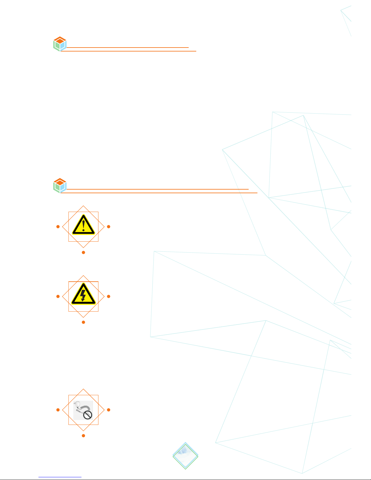
Read carefully all the following safety precautions to
● Use proper power cord.Please use power cord
specified for this product and certified for use of
your country/region .
● Connect and disconnect properly.Do not connect or
disconnect probe or test leads while they are
connected to voltage source, disconnect the
testing circuit before connecting or disconnecting
the probe.
● Observe all the terminal ratings.To avoid fire or
shock hazard, please do not measure signals at
DC40V or above to avoid damage to the
device.Consult the product manual for further
rating information before making connections to
the device.
● Do not operate in wet/damp conditions.
● Do not operate in a potentially inflammable/explosi
environment.
● Please keep the surface of the product clean and dry.

III. Functions
2
Analog bandwidth
0-200KHz
Maximum sampling rate 1MSa/s
Maximum sample
memory depth
8K
Horizontal sensitivity
Vertical sensitivity
20mV/Div~10V/Div(x1probe)
0.2V/Div~100V/Div(x10probe)
Analog input impedance
>500KΩ
Maximum input voltage
40Vpp(x1probe)
Coupling
AC/DC
Synchronous mode
Auto,Normal,Single,Scan
Auto measurement
Inbuilt signal Generator
10Hz~1MHz
(1-2-5sequence step)
Storage:
8MB Flash
Trigger mode
1uS/Div~2S/Div
(1-2-5sequence step)
Rising/Falling edge trigger
Ascend/Descend Edge
Tirgger Mode
Signal sequence/cycle/duty ratio,
peak voltage/virtual value/
max value/min value/average

3
Screen
2.8'' full color TFT LCD
Screen Resolution
320×240
Display color
65K
PC Comection
Via micro USB Cable
Recharging
Via micro USB Cable
Size
106mm×55.5mm×11mm
Battery
500mAH
Weight
66g
IV. Parameters
V. Operational Environment
Humidity:
HighTemperature 50°C,0%~60%RH:40°C~
LowTemperature: ~0°C ~ 40°C,10% 90%RH
HighTemperature: 60°C,5%~60%RH40°C ~
0°C ~ 40°C,5% 90%RHLowTemperature: ~
Operating
Conditions
Non-Operating
Conditions

VI. General Inspections
VII. Functional Inspections
Make a quick inspection of functions to ensure the device is working
soundly.Please perform following steps:
1.Turn on power and access to the homepage of the oscilloscope.
2. Place in the standard signal (e.g. square wave 1 KHz, Vpp=5V),
Insert X1 probe’s MCX end to CH A or CH B, and the probe to “WAVE
OUT”.Connect the oscilloscope with standard signals (e.g. square
wave1KHz, Vpp=5V), plug oscilloscope probe to the Input Channel,
set the switch on probe tip as 1X, connect the oscilloscope probe to
the Input Channel, align the probe slot with the socket and then plug
in.
4
VIII. Batter y Charging Instructions
When the battery voltage status turns to “ ” or display
brightness is relatively dim, please charge the battery in time;
charging is workable in both power-on and off mode.
When you get a new DS211 oscilloscope, you are advised to inspect
the product by the following steps.
1. Inspect damages caused by shipping.If the packaging carton or
the protection pad is seriously damaged, keep the package until the
oscilloscope & accessories pass the electrical and the mechanical test.
2. Inspect the product.Please contact the dealer if the following
problems occur to DS211: 1) product appearance is damaged, 2)
product doesn't work properly, 3) product does not pass performance
test.If the damage to DS211 is resulted from shipping, please keep
the package.
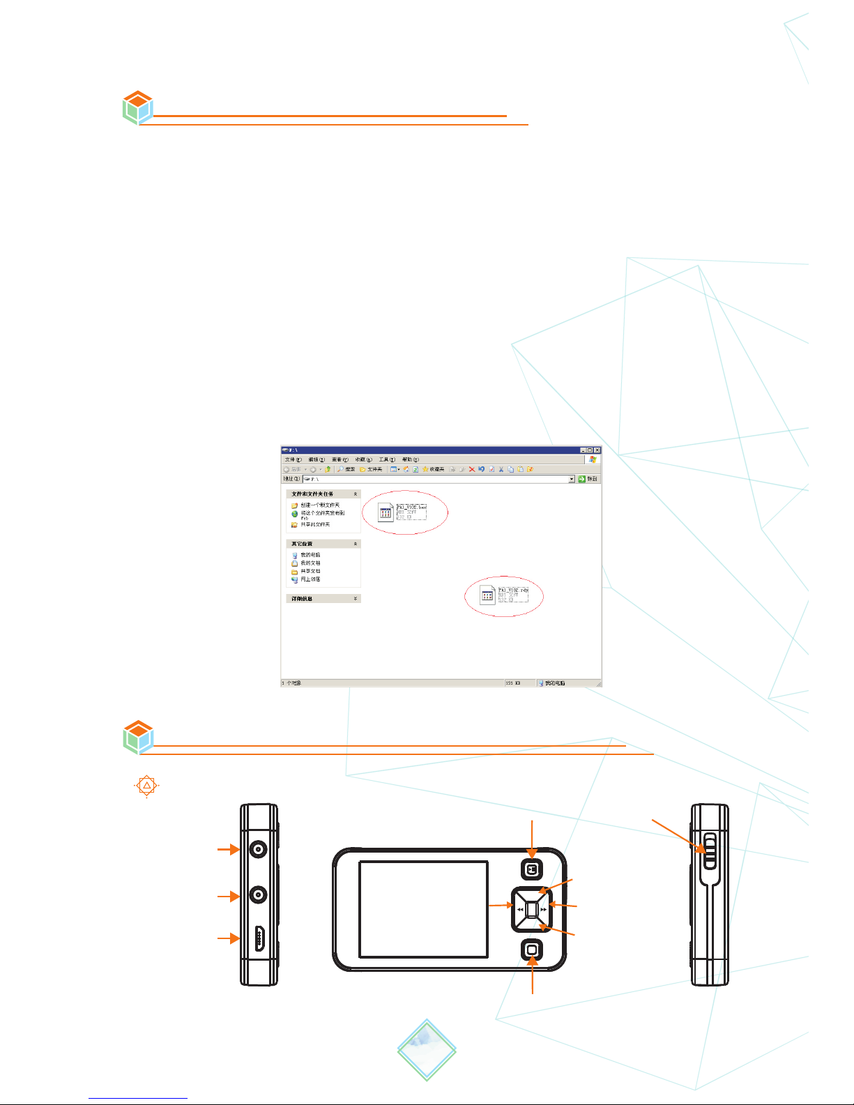
IX. Firmware Upgrading
To upgrade the firmware of oscilloscope, please carry out the
operationfollow the steps below:
1. Open web browser to visit www.minidso.com, download the newest
firmware appropriate toof your oscilloscope to your PC.
2. Press “—” button on DS211 and switch on the Power to enter into
DFU firmware upgrading mode.
3. Use USB data cord to connect DS211 to your PC, and a removable
hard disk named:“DFU V3_60_D” will appear on your PC; copy the
hex firmware to the root directory of that disk, after the extension of
the firmware changes from “hex” to “rdy”,restart DS211, and then the
upgrading process is finished.
5
X. Getting Familiar with Device
1、Interfaces & Buttons
Menu
Sign al Input
Sign al Output
USB
Stop
Powe r
Up
Down
M
+
-
Righ t
Left
INP
OUT
USB
OFF
6
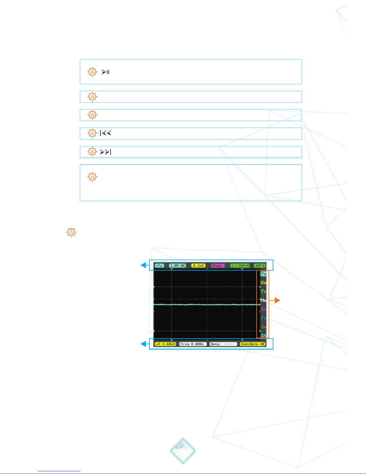
2、Main Screen Introduction
Main Screen
Parameters
Options
A B
C
D E F
G
See below for functions of each button:
Note that each item's color in Parameter Area is the same
as that in Measurement Area.
Run/pause button
Save parameter
Slide Up
+
Slide Down
-
Set parameter(Reduce,Slide Left)
On/Off Sub-menu
Save BMP(long press)
M
Auto Fit(double press)
Set parameter(Increase,Slide Right)
H
I J K L
Parameters

XI. Measurement Instructions
1、Parameters Introduction
7
Menu
Functions
(Press or to operate)
Options
B
Ordinate unit amplitude
20mV—10V(1-2-5stepping)
D
Abscissa unit amplitude
1uS—2S(1-2-5 )stepping
E
Double waveform calculation
(Inp refers to current waveform;
D/Data refers to waveform
saved previously)
-Inp/Data/-Data/Inp+D/
D-Inp/Inp-D
F
Trigmode:Rising/
falling edge
G
Trigger accuracy
±40mV—±3.9V
H
Automatic/Normal/Single/Scan
AUTO/NORM/SINGL/SCAN
A
Battery supply/USB charging
I
▲V:10.0V/
▲T:1.6mS/
Sub-item parameters
Vertical cursor parameters /
horizontal cursor parameters /
sub item parameter
J
Freq
Signal frequecy
K
Freq/Duty/
Vrms/Vavg/
Vp-p/Vmax/
Vmin
Signal frequency/Duty/
Root Mean Square voltage/
Average voltage/Min voltage
Peak-to-peak voltage/
Max voltage
L
Storage depth/File manage
SmplDpth:4K/Save001.BMP
AC/ DC coupling method

8
2、Options Introduction
Options
Yn
Xn
Tr
Me
Ex
Fn
Sn
St
Parameter Notes
Y-axis function setting (See P9)
X-axis function setting (See P9)
Trigger function setting (See P10)
Measurement function setting (See P10)
Waveform calculation function setting (See P11)
Saving and loading function setting (See P12)
Waveform output parameter setting (See P13)
System function setting (See P13)
Note: After all the changes to setting are finished, long press “ ”
to save the changes in accordance with prompts.
3、Specific Parameter Introduction
Option Setting Method
Use the "+" or "-" key to choose the options on the sliding option
area, press “M” to unfold option setting menu; use the "+" or "-"
key to select the parameter option you need and change the
current parameter value at blinking cursor via the “ ” or “ ”key.
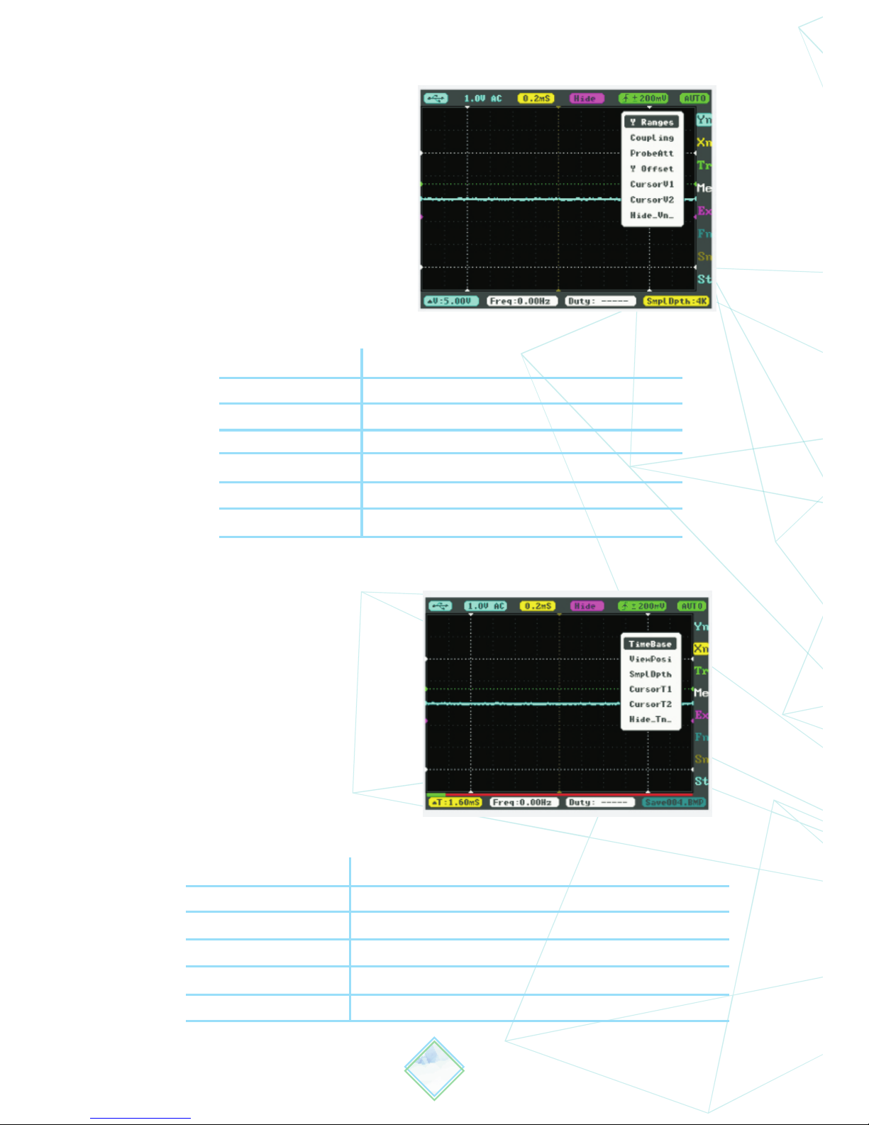
1)Yn Parameter Notes
2)Xn Parameter Notes
9
TimeBase
ViewPosi
SmplDpth
CursorT1
CursorT2
Hide_Tn_
Abscissa unit amplitude
Move horizontally to check waveform
(1k~8k)storage depth
Time measurement cursorT1
Time measurement cursorT2
Show/hide measurement cursor
Y Ranges
Coupling
ProbeAtt
Y Offset
CursorV1
CursorV2
Hide_Vn
Ordinate unit amplitude
Coupling method
Probe multiple choice X1/X10
Wave adjustment Y axis
measurement cursor V1
measurement cursor V2
Show/hide measurement cursor

3)Tr Parameter Notes
SyncMode
TrigMode
Auto Fit
Threshol
Hide_Tri
Synchronous mode
AUTO/NORM/SINGL/SCAN
trigger mode: Rising/falling edge
Automatic adjustment(Icon "F" will appear when
open, doublr click Button M to auto fit.
Horizontal Triggering Position Level)
Horizontal Triggering accuracy
Display/Hide Horizontal Triggering Position Level
4)Me Parameter Notes
Freq
Duty
Vrms
Vavg
Vp-p
Vmax
Vmin
Signal frequency
duty ratio
effective voltage value
average value
peak-to-peak value
maximum value
minimum value
10
Sensitiv

5)Ex Parameter Notes
Ext Refn
Ext Posi
Ext Hide
-Inp/Data/-Data/Inp+D/D-Inp/Inp-D
Signal position
Show/hide signal calculation
Hide the two waveform computation line (purple line):
11
Position the cursor on "EX" option, press "M” to pop-up window,
select "Ext Hide" option, and change the parameter value at the
blinking cursor to “Hide” via “ ” or “ ”, then the two waveform
computation line (purple line) will be hidden, as shown in the
following figure.

6)Fn Parameter Notes
Save Bmp
Save Dat
Save Buf
Save Csv
Save Svg
Load Dat
Load Buf
Save bmp file (waveform figure) into flash disk
Save dat file into flash disk
Save buf file (sampling buffer data) into flash disk
Save csv file (export sampling buffer data) into flash disk
Save svg file (sampling buffer figure) into flash disk
Load Dat file
Load Buf file
12
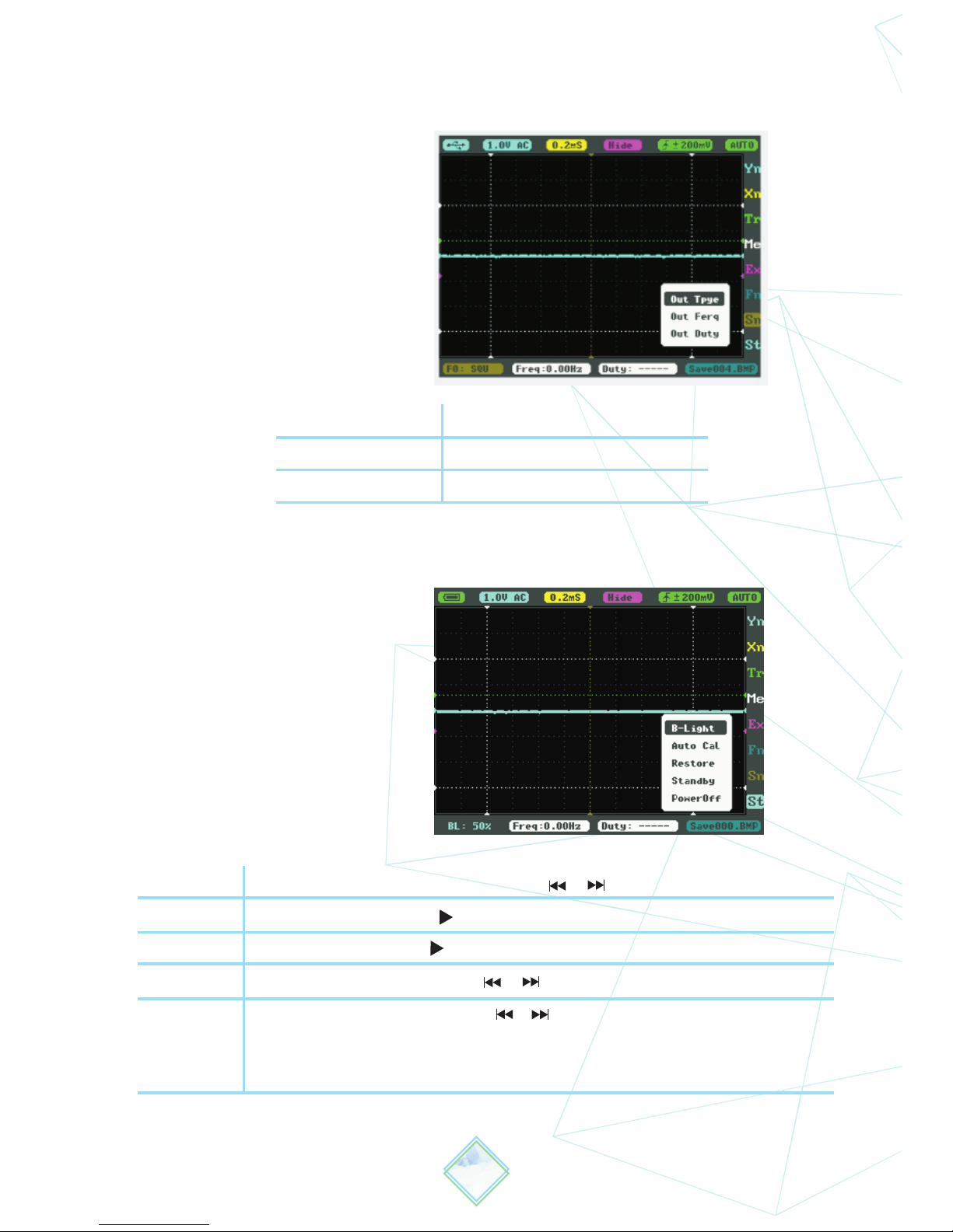
8)St Parameter Notes
B-Light
Auto Cal
Restore
Standby
PowerOff
Adjust backlight brightness(Press or to adjust brightness)
Calibrate Zero(Press to auto calibrate, save setting per prompt)
Restore Data(Press to auto calibration, save setting per prompt)
Adjust standby time(Press or to choose a standby time of 0-60 mins)
Adjust power off time(Press or to choose a power-off timeof 0-60 mins)
When connected to PC via USB data cord, it will not activate auto
power-off.
7)Sn Parameter Notes
Out Type
Out Freq
Out Duty
Output signal type
Output signal frequecy
Output signal duty cycle
13

FCC compliance statement
This device is complied with the regulation in the 15th
part of FCCregulation. Operation is subject to the
following two conditions:
(1)This device may not cause harmful interference.
(2)This device must ac ce pt any interferenc e
received, including theinterference that may cause
undesired operation.
The CE mark is a registered trademark of European
Community.
This CE mark shows that the product complies with
all the relevant European Legal Directives.
Do not dispose in domestice household waste
!
● This device complies with the WEEE Directive
(2002/96/EC)
marking requirement. This affixed product label
indicates that you must not discard this electrical or
electronic product in domestichousehold waste.
● Disposal and recycling: you must dispose the mini
oscilloscope according to local law and regulations.
As the oscilloscope contains electronic building brick
and battery, you must dispose it respectively with
garbage.
● Please dispose the battery in accordance with
local environmental regulations.
XII. Certification Marks
14
 Loading...