

User Manual
DSO NoteII
Made in China
Design by SAIN SMART
● Read carefully all the following safety precautions to avoid personal injury and prevent damage
to the device or any products connected to it. Failure to follow these safety instructions could
result in personal injuries or risk of fire.
● Use proper power cord. Please use power cord specified for this product and certified for your
country/district of use.
● Connect and disconnect properly. Do not connect or disconnect probe or test leads while they
are connected to voltage source.Before you connect or disconnect current probes, please
disconnect power to the circuit under test.
● Observe all the terminal ratings. To avoid fire or shock hazard, please do not measure signals
at DC40V or above.Please read the User Manual carefully to learn more about ratings before
connection.
● Do not operate in a humid environment.
● Do not operate in a potentially inflammable/explosive atmosphere.
● Please keep the device surface clean and dry.
Safety Statement
1. General Safety Information
- 2 -
Contents
Safety Statement
DSO NOTE II Overview
Interface Introduction
Getting Started
Functional Overview
Product Inspection
Battery Disposal
Technical Support
- 1 -
2
3
7
11
18
24
25
26

DSO NOTE II Overview
2. Operating Environment
Operating Environment
Temperature
Humidity
Requirement
Operating Condition: +0°C to 50°c
Non-operating Condition: -20°c to +60°c
Operating Condition: High Temperature:40°C to 50°C,0% to 90%RH
Low Temperature : 0° C to 40°C,10% to 90%RH
Non-operating Condition: High temperature:40°C to 60°C,5% to 95%RH
Low temperature:0° C to 40°C,5% to 95%RH
1. Specifications
Performance parameters
- 3 -
Functionalities
Coupling
Analog bandwidth
Maximum sampling rate
Analog input impedance
Maximum input voltage
Maximum sample memory depth
Horizontal sensitivity
Vertical sensitivity
AC/DC
1MHz
10MSa/s
1MΩ
±40V(X1 probe)
8K
1uS/Div~2S/Div(in 1-2-5 sequence step)
20mv/Div~10V/Div (in 1-2-5 sequence step)
Modes
Trigger mode
Synchronous mode
Math waveforms
Auto measurement
Inbuilt signal Generator
Vertical precise, horizontal precise measurement andtrigger threshold
Rising/Falling edge trigger
Auto,Normal,Single,None,Scan
A,-B,A+B,A-B,RecA,RecB,RecC
frequency, cycle time, duty cycle,DC RMS voltage/Vpp /Vmax/Vmin/Vavg
10Hz~1MHz square wave (duty adjustable) or 10Hz~20KHz Sine/Square/
Triangle/Sawtooth wave
- 4 -
2. Interface & Buttons
Storage
Operation
Dimension
Battery
Display
Inbuilt 8MB U disk storage for waveform data and images
Capacitive touchscreen,supporting swipe gestures
(100mm×56.5mm×10.7mm)
Internal 550mAh Lithium battery, external USB port
Color TFT LCD display (320X240 pixels)
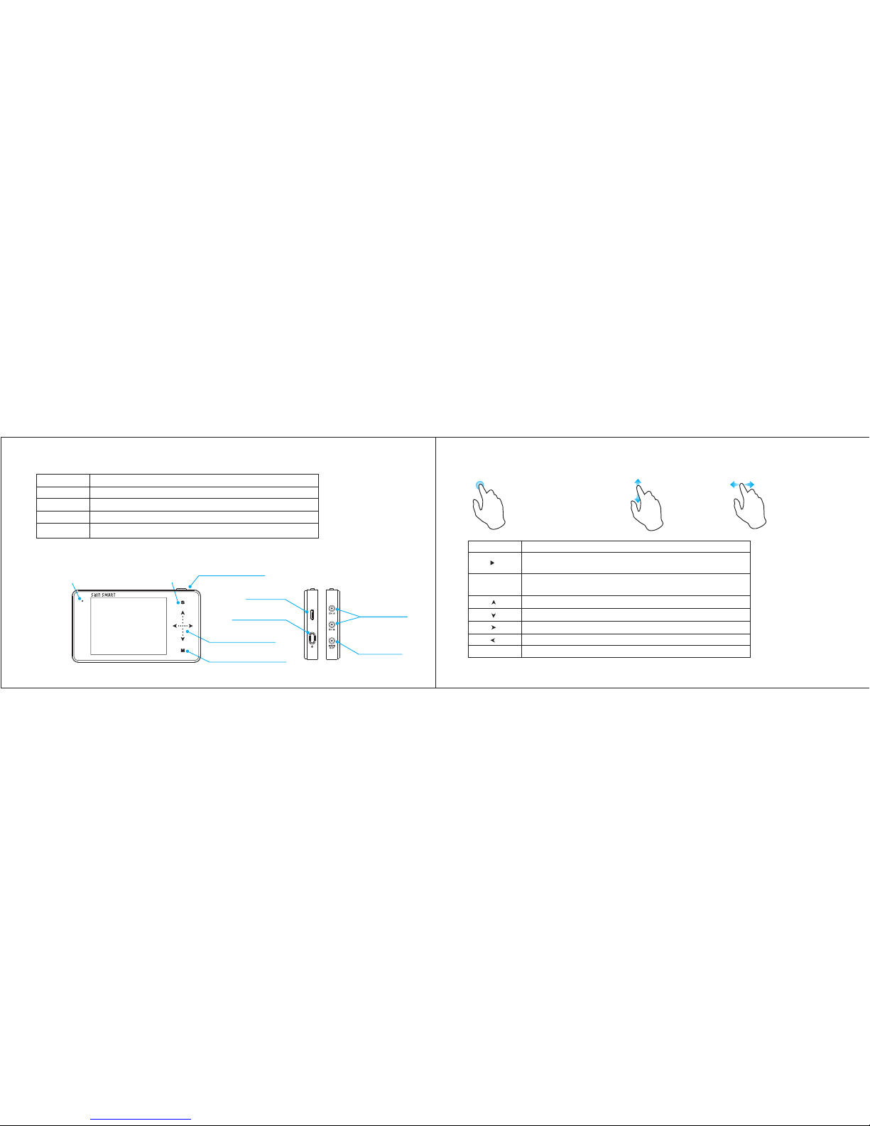
Product parameters
Run /Paus e Butto n
Sli de opti on area
Sub -menu s elect ion
Cha rge ind icato r
Sel ectio n/Con firma tion &
Dis play/ Hi de m enu
USB
Pow er Butt on
USB P ort
Wave O ut
Sig nal Inp ut
Sta ndby in dicat or
DSO NOTE II
- 5 -
3. Operation on option area
● Capacitive touchscreen
● Supporting swipe gestures
● Tap
● Vertical slide ● Horizontal slide
M
s
||
Button
Function
1) Run/Pause
2) Save current parameter/screen display(long
1) Menu display/hide
2) Sub-menu confirmation
Upward selection(Slide Up)
Downward selection( Slide Down)
Reset Parameters(Tap Right/Increase, Slide Right)
Reset Parameters(Tap Left/Reduce, Slide Left)
Sub-menu On/Off
* Note that each item's
color in Parameter Area
is the same as that in
Measurement Area.
- 6 -
Interface Introduction
Function
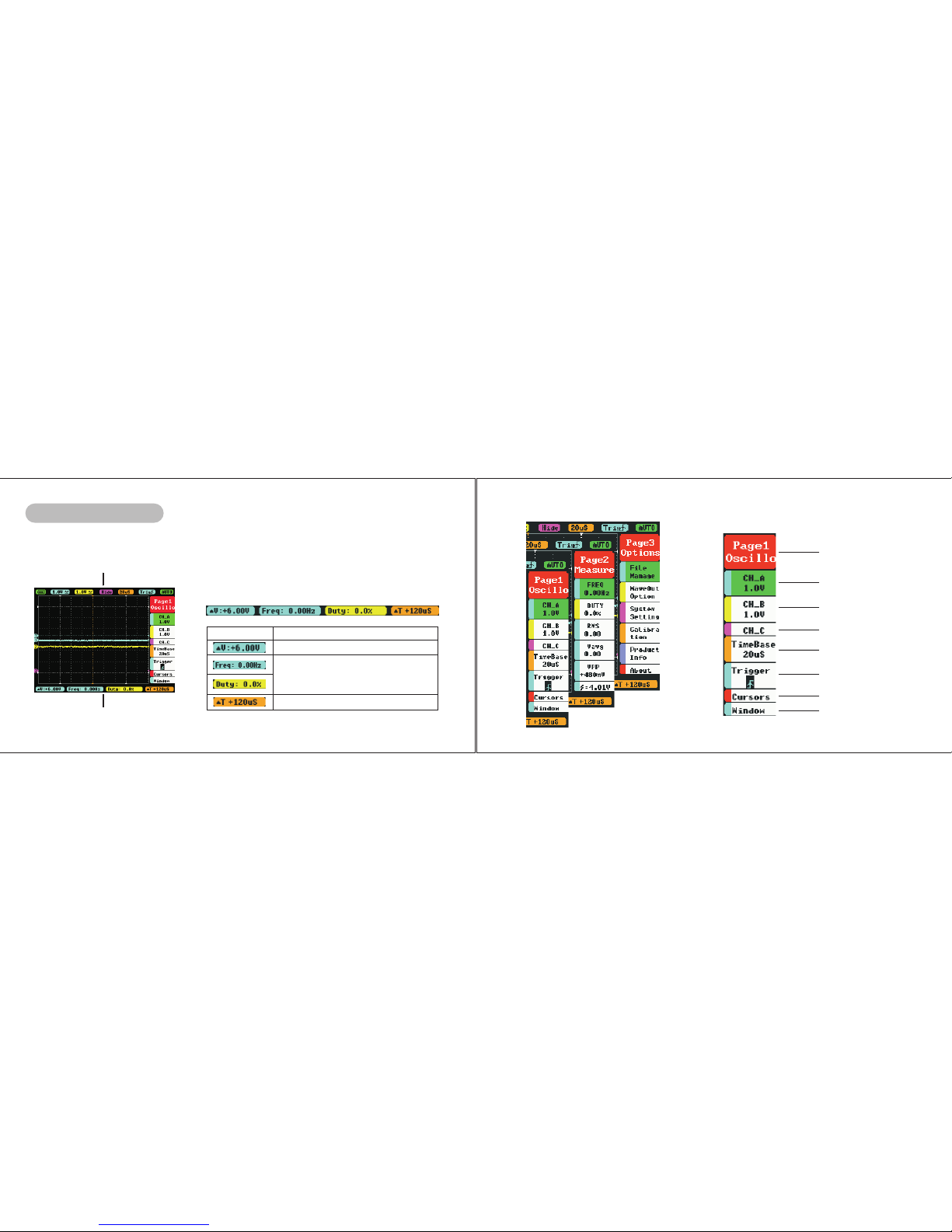
1. Home screen introduction
a.Measurement area
a.Measurement area introduction
b.Option area
c.Parameter area
Menu
△ V=V1-V2
Measured Value (Blue corresponds
with Channel A,Yellow with Channel B)
corresponding the 1st and 2nd item in
Page2
△ T=T2-T1
- 7 -
b.Option area introduction
Page1(oscilloscope)
A channel option
B channel option
C channel option
TimeBase option
Trigger option
Vernier option
Horizontal window
- 8 -
 Loading...