


CREALITY ENDER-3 V2 3D PRINTER
USER MANUAL
V1.0 Jul 2020

Contents
I. Welcome
II. NOTICES
III. Printer Components
IV. Parts Identification
V. ASSEMBLY
VI. CONTROLING THE PRINTER
VII. PREPARING FOR USE
......................................................................................................................................
.....................................................................................................................................
................................................................................................................
.................................................................................................................
................................................................................................................................
...............................................................................................
..........................................................................................................
VIII. PRINTING YOUR OWN MODELS - SLICERS
IX. MAINTENANCE
X. PROBLEM SOLVING
.......................................................................................................................
...............................................................................................................
...................................................................
02
04
06
07
09
19
23
29
31
38
01

I. Welcome
Thank you for purchasing the Creality Ender 3 V2 3D Printer from SainSmart.
This Ender-3 V2 3D Printer User Guide is designed to aid Ender-3 V2 users in the assembly and use of their new printer and to help
in getting started with 3D Printing. Even if you are familiar with 3D printing technology, we still recommend that you read through this
user manual, as there is a lot of important information about the Ender-3 V2 for you to get a better 3D printing experience.
Support:
● Documentation like this user manual, help guide etc. can be found on https://docs.sainsmart.com/
● For technical support, please email us at support@sainsmart.com.
● Help and support is also available from our Facebook group. (SainSmart 3D Printing User Group)
Scan QR code
to join the group
02

Basic Specifications
Model
Print Size
Printing Method
Number of Nozzles
Recommended Layer Thickness
Stock Nozzle Diameter
XY Axis Precision
Filament Diameter
File Format
Connectivity
Compatible Slicers
Power Specification
Total Power
Build Plate Temperature
Nozzle Temperature
Resume Printing
Filament Sensor
Dual Z-axis Screws
Language
Operating System
Print Speed
Ender-3 V2
220 x 220 x 250mm. (Build Plate size 235 x 235mm)
FDM (Fused Deposition Modelling)
1
0.1mm - 0.4mm
0.4mm
±0.2mm
Φ1.75mm
.gcode (see your slicer software for supported model formats)
Micro SD Card / USB
Cura, 3D Creator Slicer, Repetier-Host, Simplify3D and more
Input: AC 115/230V 50/60Hz Output: DC 24V
350W
≤100°C
≤250°C
Yes after Manual pause or Power failure
No
No
English / Chinese
Marlin. Slicers are available for Windows XP/Vista/7/10/Mac OS/Linux
≤180mm/s, Normally operation is 30-60mm/s.
03

II. NOTICES
Please read all the instructions in the manual and familiarize yourself with the Ender-3 V2 3D Printer User Manual before setting-up
and using your 3D printer
PLEASE FOLLOW ALL THE SAFETY WARNINGS AND NOTICES.
Failure to comply with the warnings and instructions may result in individual injury, inferior results and printer damage.
1. Work Environment and Safety
Keep your workplace tidy. Do not operate the 3D Printer in the presence of flammable liquids, gas or dust.
The printer should be placed out of the reach of children or pets.
Only operate your 3D printer in room temperatures of 5-30℃ with an ambient humidity between 20%-70%
2. Electrical Safety
● Always use a properly grounded outlet and the cable provided to prevent damage to your printer.
● Please unplug the 3D Printer if it will not be in use for a while.
● Do not use outdoors, indoor use only.
● Always keep the printer in a dry environment and out of direct sunlight.
● Do not use the 3D Printer during thunderstorms.
3. Personal Safety
● Do keep your hair, clothing and gloves away from moving parts.
● Do not operate the 3D Printer while you are tired or under the influence of drugs, alcohol or medication.
● Parts of the 3D printer will get very hot during use, Do not touch the nozzle, hot end assembly or the build plate when the printer
is warming up, printing or cooling down.
● Ensure you keep others, especially children and pets away from the printer.
04

4. CAUTION!
● Do not leave the 3D Printer unattended.
● Do not make any modifications to the printer other than any approved SainSmart upgrades.
● When removing a model be careful not to use excessive force.
● The 3D printer must only be operated in a well ventilated area, noxious gasses can be released.
● Do not exceed the maximum print temperature of your printer or the filament you are using.
● When loading or unloading filament make sure the printer nozzle is well clear of the build plate (>50mm).
5. Filament and storage
● Follow any recommendations of your filament manufacturer.
● Do not use your printer to make anything that will come into contact with food unless specifically allowed by the filament manufacturer.
● Filament should be stored in clean and dry conditions. Filaments will absorb moisture and degrade over time if not kept dry.
● Do not open the filament from it’s sealed package until it is needed.
05
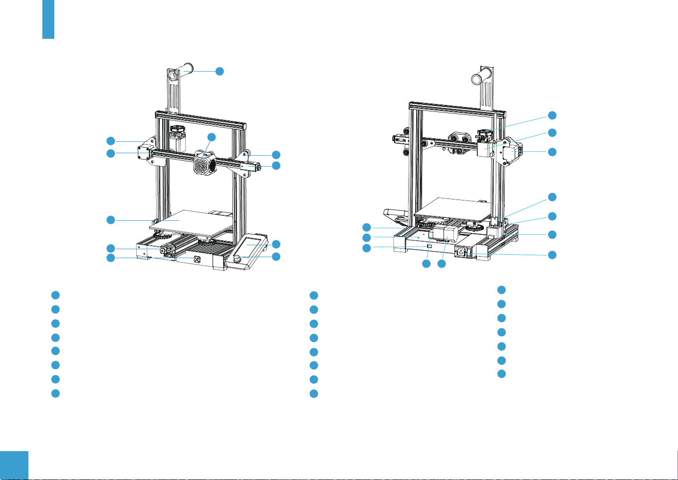
III. Printer Components
7
17
1
2
3
4
5
1
X and E-axis Assembly
2
X-axis Limit Switch
3
Printing Platform with Glass Bed and clips.
4
Y-axis belt Tensioner
5
Tool Box
6
Nozzle Assembly
7
Filament Spool Holder
8
Z-axis Roller Bracket Assembly
6
18
8
9
12
10
11
9
X-axis belt Tensioner
10
Screen
11
Rotary and press Switch
12
Machine Base
13
Power Supply
14
Voltage Selector
15
Y-axis Limit Switch
16
Y-axis Motor
13
14
15 16
17
Extruder Knob
18
E-axis Motor
19
X-axis Motor
20
Coupling
21
Z-axis Limit Switch
22
Z-axis Motor
23
Power Switch and Socket
19
20
21
22
23
06

IV. Parts Identification
1
Printer Base x 1 Display Assembly x 1 Nozzle Assembly x 1
5 6 7 8
X-axis Tensioner x 1 Z-axis Motor Assembly x 1
9
Z-axis Profile
10 11
(left) x 1
2
Z-axis Profile
(right) x 1
Gantry Profile x 1
3
Z-axis Limit Switch
Assembly x 1
12
X-axis Profile x 1
Z-axis Roller Bracket
4
Assembly
XE-axis Assembly x 1
13
Lead Screw x 1
07
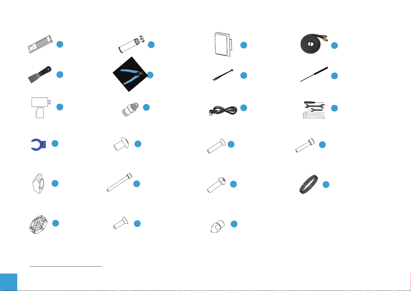
Filament Holder
14
Upright x 1
Filament Holder
15
Pipe and Nut x 1
2020 Profile
16
Cover x 2
17
Drive Belt x 1
Metal
18
Scraper x 1
SD Card and
22
Card Reader x 1
26
Joint Claw x 2
30
M5T Nut x 2
Extruder
34
Knob x 1
Diagonal
19
Cutters x 1
Bowden Tube
23
Connector x 2
Hexagon Socket
27
Flat Round Head
Screw M5X8 x 2
Hexagon Socket
Head Spring Washer
31
Combination Screw
M5X45 x 5
Hexagon Socket
Countersunk Head
35
Screw (black)
M4X14 x 1
20
Cable Tie x 1
Power
24
Cable x 1
Hexagon Socket
28
Countersunk Head
Screw M4X18 x 2
Hexagon Socket
Flat Round Head
32
Spring Washer
Combination
36
Nozzle x 1
21
Needle x 1
Wrenches and
25
Screwdrivers x 1
Hexagon Socket
Head Spring Washer
29
Combination Screw
33
Filament x 1
08
Please make sure all the above parts are included. If you are missing any part or have any questions, please email us at
support@sainsmart.com.
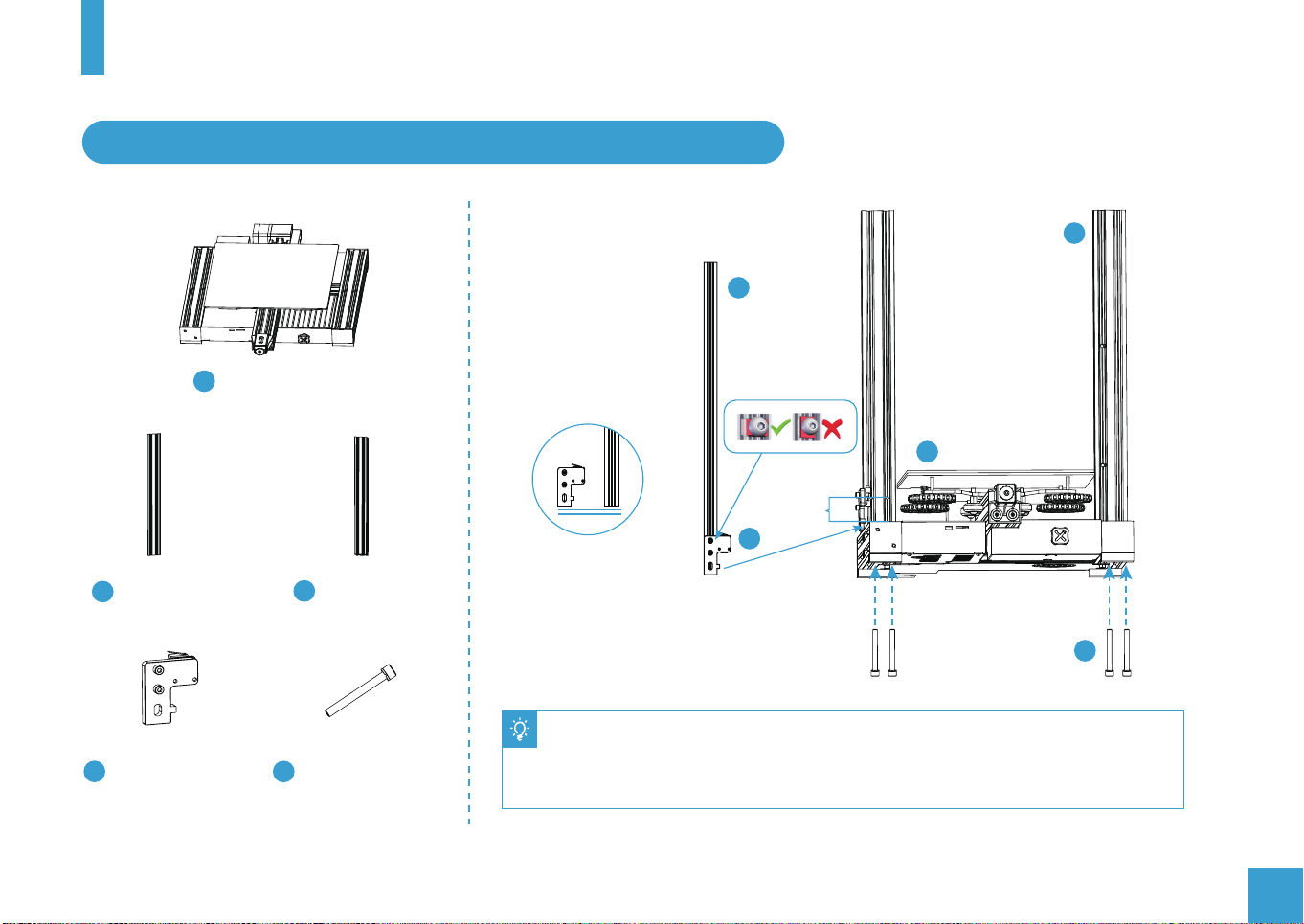
V. ASSEMBLY
1. Install Z-axis Limit Switch Assembly and Z-axis Profiles
9
Printer Base x 1
1
10
1
Short
7
Z-axis Profile
9
(left) x 1
Z-axis Limit Switch
7
Assembly x 1
Z-axis Profile
10
(right) x 1
Hexagon Socket
Head Spring Washer
31
Combination Screw
M5X45 x 5
31
● Slide the Z axis limit switch onto the Z-axis Profile (left) as in the picture above and
loosely tighten. Then use four M5X45 screw to fix the Z-axis profiles to the base.
● Slide the Z axis limit switch down until it touches the base profile and tighten the bolts.
09
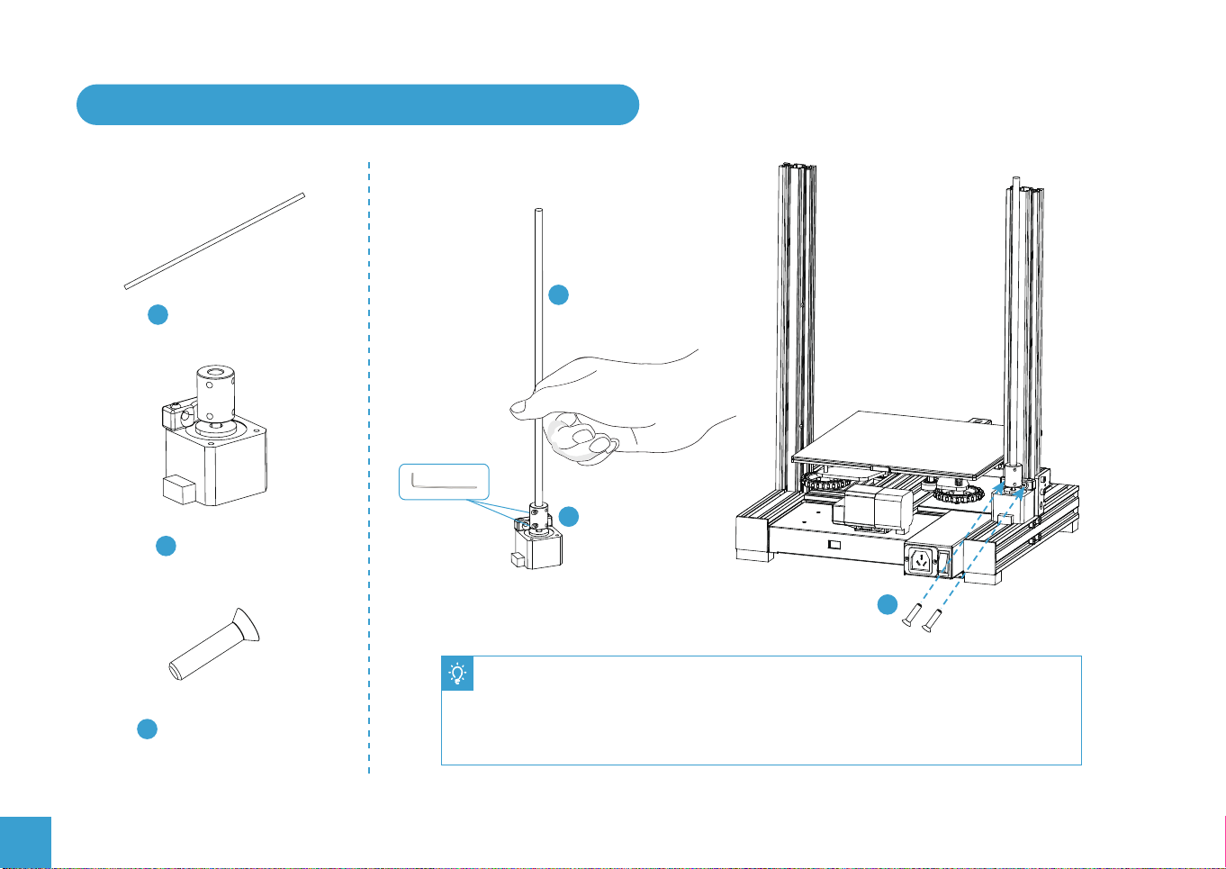
2. Install Z-axis Motor Assembly and Lead Screw
13
13
Lead Screw x 1
6
Z-axis Motor
6
Assembly x 1
28
10
Hexagon Socket
28
Countersunk Head
Screw M4X18 x 2
● Attach the motor to the profile using two M4x18 screws it needs to be secure but do
not over tighten.
● Slide the lead screw into the top of the coupler and tighten the set screw to clamp it
securely in place.
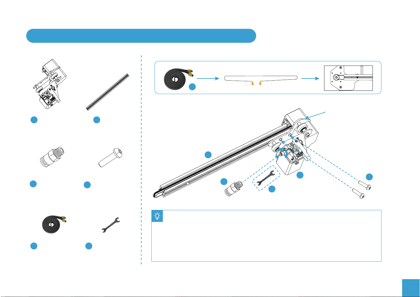
3. Install Pneumatic Joint, XE-axis Assembly and Drive Belt
17
XE-axis
8
Assembly x 1
12
X-axis
Profile x 1
12
Install the drive belt
around the pulley.
Bowden Tube
23
Connector x 2
Drive Belt x 1
17
Hexagon Socket
Flat Round Head
32
Spring Washer
Combination
Wrenches and
25
Screwdrivers x 1
8
23
25
● Tighten the Bowden tube connector firmly into the Extruder using an open-end wrench.
● Align the bolt head on the XE-Axis Assembly into the hole on the X Axis profile.
● Secure the XE-axis Assembly to the X-Axis Profile with two M4X16 screws. (Insert the
Allen key through the holes on the outer plate).
● Install the Drive belt round the pulley inside the XE-axis Assembly with the toothed side
round the pulley as shown above.
32
11
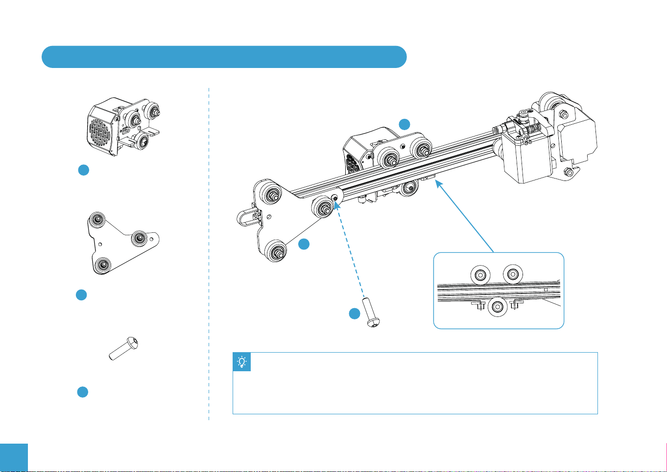
4. Install Nozzle Assembly, Z-axis Roller Bracket Assembly
3
Nozzle Assembly x 1
4
Z-axis Roller Bracket
4
Assembly
32
3
Back View
12
Hexagon Socket
Flat Round Head
32
Spring Washer
Combination
● Make sure the drive belt is in the profile slot and slide the Nozzle assembly onto the profile
as shown above.
● Attach the Z-Axis Roller Bracket Assembly to the profile, aligning the bolt head into the
hole on the profile and using the M4x16 screw into the threaded hole in the profile.
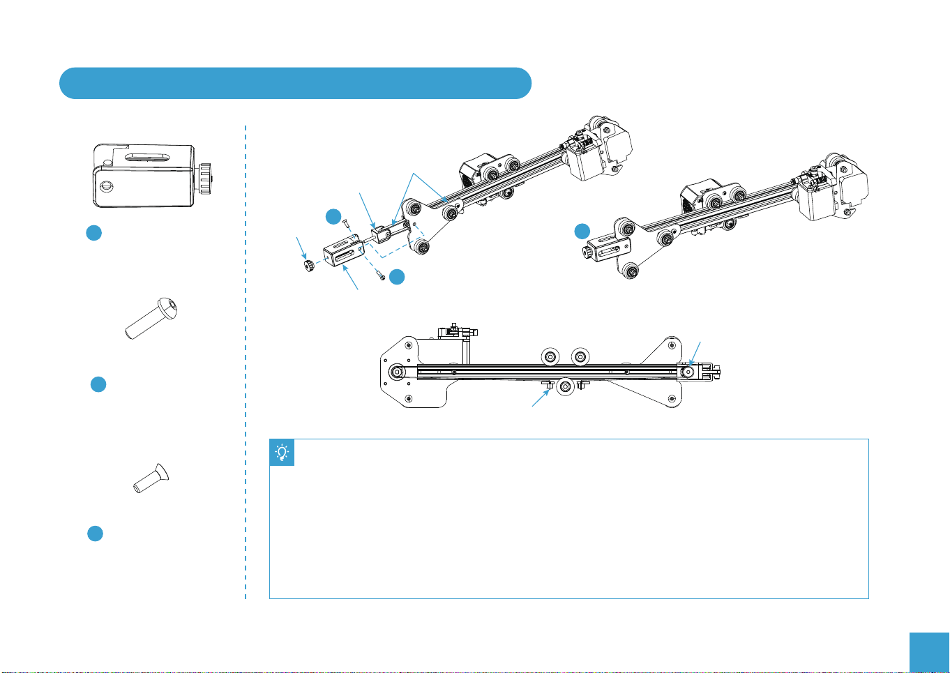
5. Install X-axis Tensioner and Connect the Drive Belt
Drive Belt
Tensioner
block
35
Installation Illustration Completed installation
32
5
X-axis Tensioner x 1
Tensioning
Knob
X-axis tensioner base
5
Hexagon Socket
Flat Round Head
32
Spring Washer
Combination
Hexagon Socket
Countersunk Head
35
Screw (black)
M4X14 x 1
Back View
copper sleeve
● Undo the tensioning knob and remove the tensioner block.
● Thread the drive belt around the pulley making sure it has not twisted and push the pulley back into the
tensioner base making the alignment is as shown in the picture above.
● Screw the tensioning knob back into place by couple of turns.
● Attach the Tensioner base to the profile Z Axis Roller Bracket assembly with a M4X16 screw on one side
and the countersunk screw (in the Tensioner block bag) on the other, both these screws use the same
threaded hole in the profile.
● Secure the ends of the drive belt by sliding the belt into the slots in the Nozzle assembly as in the picture
above.
Tensioner block
13

6. Install the Z-axis Gantry Assembly and Adjust X-axis and Y-axis Drive Belt Tension
Assembled Part After Step 5
Assembled Part After Step 2
Back
Front
A
● Turn the X-axis and Y-axis tensioner
knobs to adjust the belt tension.
A
● The belts should be taught but not over-
tight or too slack. When you press down
the drive belt, you should feel some
spring in the belt.
● If the belts are too lose they can slip
during printing ruining the result.
● If the belts are too tight they will over
stress the pulleys and motors or even
break.
B
B
● Place the lower V rollers into the grooves on the outside of the Z profiles.
● Locate the lead screw in the Brass nut on the XE Assembly and turn by hand to
screw the gantry down while guiding the other V rollers into the Z profile grooves.
● Adjust the tension of the X and Y axes drive belts as shown above.
14

7. Install the Gantry Profile and Display Assembly
29
11
Gantry Profile x 1
2
Display Assembly x 1
● Secure the Gantry profile onto the upper end of the gantry with four hexagon socket head
cap screws M5x25 and tighten securely:
● Unclip the display from the bracket, slacken the screws pre-installed on the bracket and
Hexagon Socket
29
Head Spring Washer
Combination Screw
insert the T nuts into the base profile.
● Tighten the bolts making sure the T nuts are turning to engage with the base profile.
● The display can be moved forwards and backwards to suit your preference then tighten
the bolts.
● Connect the ribbon cable to the display screen and clip it back onto the bracket.
11
Connect the display
screen Assembly
2
15

8. Install Filament Holder, Gantry Cover and Extruder Knob
Filament Holder
14
Upright x 1
Filament Holder
15
Pipe and Nut x 1
2020 Profile
16
Cover x 2
Hexagon Socket
27
Flat Round Head
Screw M5X8 x 2
30
M5T Nut x 2
Extruder
34
Knob x 1
15
16
● Insert the M5X8 bolts through the holes on the Filament holder upright and loosely attach the T nuts.
● Align the T Nuts in the top profile groove (The flat side faces towards the back of the printer) and
tighten the nuts, the T nuts will turn in the grove as it tightens.
● Attach the filament holder and secure with the plastic nut.
● Place the extruder knob onto the top of the extruder motor shaft and push the profile covers in on
both sides of the top profile.
14
27
30
34
16

9. Connect the Bowden Tube to the Extruder
Joint Claw x 2
26
Bowden Tube
● Press the collar on the extruder Pneumatic Connector in to the fitting and hold.
● Press the Bowden tube into the connector firmly until it goes no further.
● Release the collar.
● Clip the Connector spacer between the collar and the body of the connector to lock in place.
17

10. Electrical Connections
24
Power Cable x 1
18
X, E, Z-axis motor port
X, Z-axis limit switch
24
E
z
Z-axis limit switch
Z轴限位开关
Z-axis motor port
Z轴电机接口
Caution
X
X
● Select the correct input voltage
to match your local supply
(115/230V)
● Damage can occur if the
voltage is set incorrectly.
● Connect the power cord and
set the power switch to 1 to
turn it on.
● Do not unplug or connect any
cables when the machine is
turned on.

VI. CONTROLING THE PRINTER
1. Display and Controls
At the base of the screen there is a single knob, this has two functions:
1. As the knob is rotated it will move, highlighting whatever option is selected at the time.
2. The knob is also a switch, by Tapping it once, you will go into the menu option that is
highlighted at the time the button is pressed.
At the bottom of the screen is a status bar which displays the current and target temperature
for the nozzle and bed temperatures,
Print speed override value and the current distance of the Z axis above the home position.
From the main screen four options are available:
Print
This allows you to select a file from the SD card to print. Once selected, the file is loaded and
the print starts while displaying print details and progress.
Prepare
This menu allows you a number of options to get your printer ready for printing, such as manually moving the axes, auto homing the
printer (returning the Nozzle to the starting position for any print), preheating the bed and nozzle to preset values, putting the printer
in cooldown mode and selecting the display language.
Control
This allows manual selection of the fan speed, nozzle and bed temperatures and the changing of some of the default values for
motion and temperatures.
Info
Shows some information such as the current firmware version.
Each menu or submenu has a Back option at the top, to return to the previous menu Highlight this and Tap.
19

2. The Print Menu
This menu displays a list of printable files in the root directory of the SD card, if the filename is too long only
the first characters will be displayed. If there is no SD card inserted or no files are found the list will be empty.
Once a file is selected, a print is started and the print details are shown.
There are 3 options selectable from the printing display Tune, Pause and Stop
20
Model
Set nozzletemperature
Current nozzletemperature
Tuning override
Printprogress
Current hot bedtemperature
Set hot bedtemperature
Z-axis height
Tune
Tune allows you to manually modify
the current print speed, nozzle and
bed temperature and the fan speed.
There is also a Z offset control
allowing the position of the Z axis to
be modified.
Pause
Pauses the print allowing it to be
resumed.
Stop
After confirmation the print is stopped
and cannot be resumed.

3. The Prepare Menu
This allows manual control of the printer to prepare it for printing.
Functions available here are:
Move
Move the nozzle around the axes of the printer manually and control the extruder. For the XYZ axe, select whichever one you want
to move and then select the new position value, relative to the home position, you want to move to. Tap to move the nozzle to the
new position.
For the extruder the position is relative to the starting position of the extruder.
Disable Stepper
Cuts power to the stepper motors via the motherboard. This protects the motherboard from currents generated by the motors when
they are moved manually. It is important to select this before moving any of the axes manually/by hand to prevent damage, even
then only move the axes manually slowly.
Auto Home
Sends the nozzle to the home position (front left bottom) and calibrates the position.
Set home Offsets
Takes the current nozzle position as the new desired home position by setting offsets from the actual home position.
Preheat PLA or ABS
Heats the bed and nozzle and runs the cooling fan to the configured values for either PLA or ABS
Cooldown
Starts a controlled cooling down of the bed and nozzle while leaving the fans running. Use this rather than just powering off the printer!
Language selection
Select and Tap to toggle the display language (English or Chinese)
21

4. The Control Menu
Allows manual control of the printer temperatures and fan speed and modifying the default values used by the Printer for various
functions..
Functions available here are:
Temperature
Selecting this shows a sub-menu with the following options:
Nozzle Temperature
Sets the desired nozzle temperature to the value you set, the nozzle will heat up or cool down accordingly.
Bed Temperature
Sets the desired heated bed temperature to the value you set, the bed will heat up or cool down accordingly.
Fan Speed
Sets the cooling fan speed to the value you set.
Preheat PLA Settings (and ABS Settings)
Sets the temperatures and fan speed for the Prepare / Preheat (PLA or ABS) options. To save any changes you must select the
Storage Configuration option or the changes will be lost on powering off the printer.
Motion
Shows a Sub-menu allowing you to change a number of maximum limits for motion settings. We recommend that you do not change
any of these settings unless you know exactly what you are doing!
Storage Configuration
Permanently saves any changes you have made in the Motion menu or in the Temperature / Preheat PLA or ABS Settings, If not
saved then the next power on will restore the original values.
22
Read Configuration
Restores all configuration values to the ones last saved overwriting any currently changed values.
Reset Configuration
Resets all parameters to the Factory Default settings.

VII. PREPARING FOR USE
1. Bed Leveling
The first and most important step to ensure the success of
3D printing is to ensure that the build plate is parallel to the
plane in which the nozzle of the extruder travels keeping
the distance to the Build plate constant. This is also called
"leveling" in 3D printing. There are four levelling points,
one near each corner of the bed, Each uses a screw and
a levelling knob to compress a spring supporting the build
plate. Turning the knob on the screw compresses or
decompresses the spring which supports the build plate.
The directions are marked on the knobs with up and down
arrows.
To level your build plate for the first time, please follow the instructions below:
● First remove the glass from the bed of the printer, prise the 2 securing clips away from the edge of the bed and remove the glass plate.
● Peel the protective film off the glass plate, make sure it is clean on both sides and that the surface of the aluminium bed is also clean.
● Tighten the levelling knobs (anti-clockwise) to compress the springs and lower the build plate, if the knob is too slack the screw
may just turn in place rather than compressing the spring. If so hold the screw thread in place while tightening the knob until it
stays in place by itself. Lower it evenly as far as it will go but be careful that the bottom of the build plate stays clear of the ends
of the Y axis drive belt which stick up underneath it.
● Refit the glass plate, it has a smooth side and a textured side, lay it smooth side down on top of the aluminium bed, make sure it
is square and attach it using the clips, one in the front centre and one in the back centre.
● Turn on the printer and from the menus go to the Prepare menu, highlight Auto Home and Tap to select. The printer will now go
through a homing sequence which moves the nozzle to the front left corner in it’s lowest position.
● ●
23

24
The levelling points are about 30mm in from each corner. There is no need to measure exactly.
Take a thin sheet of paper (Standard A4 printer paper works well) and place it on the build plate and underneath the nozzle.
To move the nozzle around you can either move it by hand, this is easy on the Y axis just slowly slide the build plate forwards and
backwards. To move the X axis either slide the nozzle slowly across the Y axis by hand or both can be moved by using the Printer
itself. If moving the axes by hand before you do so on the prepare menu select Disable Stepper motors to prevent the stepper motors
from trying to hold their position or acting as generators feeding unwanted current back into the Printer control board. When moving
the X axis be careful to only exert pressure in the horizontal direction, do not accidentally move the Z axis up or down. Moving the
axis by printer motion controls is preferred ,certainly for X axis movements, as it removes these risks.
To move an Axis using the printer controls; The coordinates for the 4 positions will be X/Y 30/30, 30/205, 205/205, 205/30
1. From the main menu select Prepare / Move then select the Axis you want to move, in this case just X and Y so select Move X and Tap.
2. It will show a position number highlighted for the selected axis, For X and Y 0 is at the home position, the numbers are measured
away from home, to the right for X and to the back for Y.
3. To change the position rotate the knob until the required position is shown and Tap to move the nozzle to that position.
4. If needed to prevent the nozzle scraping over the bed move the Z axis up by 2mm before moving the Nozzle in the X and Y axes.
But once in the desired XY position lower it back down to Zero.
When the nozzle is in position jiggle the paper back and forth while adjusting the levelling knob to raise (or lower) the build plate
until there is just the start of friction between the paper and the nozzle.
Repeat this for all 4 corner positions. As the level position of each corner can slightly affect the others for the first time levelling the
bed it is suggested that you go through the complete process a second time starting with redoing the auto home commend.
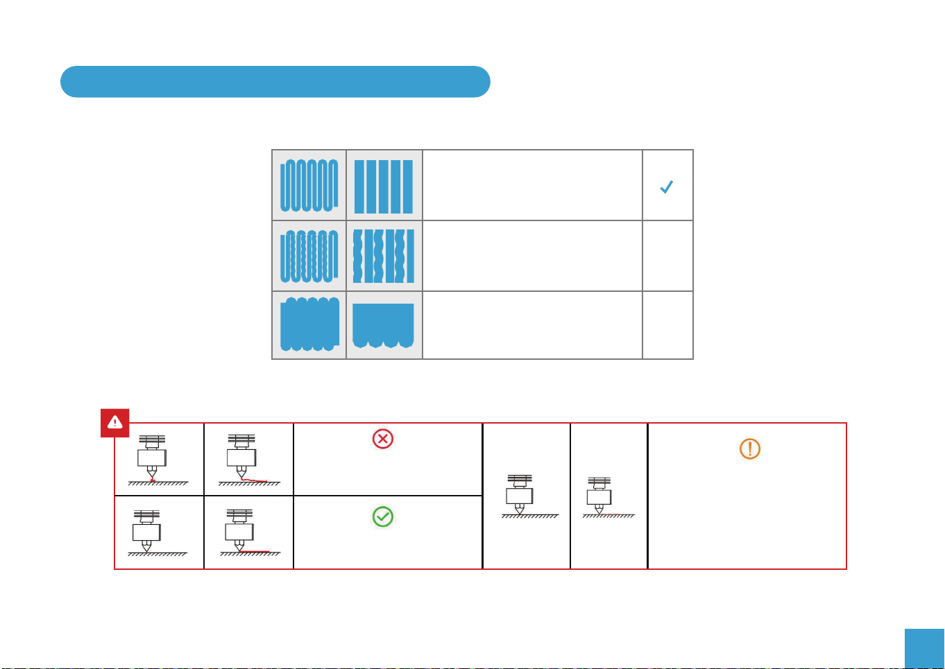
2. What a Successful First Layer should look like
The nozzle is at the correct height above
the platform.
The nozzle is too far from the platform.
This may cause the extruded material
to not stick to the build plate.
The nozzle is too close to the build plate.
This may damage the nozzle and the
build plate.
The nozzle is too far away from
the build plate, the filament cannot
adhere properly
The nozzle is at the correct height
above the build plate.
X
X
The nozzle is too close to the
build plate and the filament
cannot be fully squeezed out,
which may damage the nozzle
and build plate.
25

3. Preheating – Allowing the extruder to work
There is a safety mechanism in the firmware which prevents the extruder from working unless the nozzle is hot enough to melt the
filament. The minimum nozzle temperature before the extruder will turn is 180˚ You cannot add, remove or change the filament
unless the nozzle is hot enough for the filament to melt, even if you are disengaging the extruder and pulling or pushing the filament
manually!
To preheat both the nozzle, build plate and fan to their default settings for the filament in use:
From the main menu select Prepare / Preheat PLA or Preheat ABS. All will change to their default settings.
To control the nozzle, bed or fan separately:
From the main menu select Control / Temperature / Nozzle Temperature, Bed Temperature or Fan Speed
Dial up the value you want and Tap to implement the change.
To see or change the settings for the Preheat PLA or ABS options go to Control / Preheat PLA settings or Preheat ABS settings.
26

4. Loading or Changing Filament
1. The Nozzle must be hot to add, remove
or change filament so preheat the nozzle
before starting. Hang the filament spool
on the holder so it feeds over the top of
the spool towards the extruder..
To allow the filament to feed smoothly
cut an angle on the end of the filament
(as shown above) to help it enter the
extruder.
2. Press the lever on the extruder to separate the toothed gear and the idler.
Insert the filament into the hole in the lever, between the gear and idler and
into the hole on the other side. Keeping the lever pressed push the filament
through the Bowden tube and into the hot end and nozzle. As long as the
Nozzle is hot enough the filament should start to come out of the nozzle and
the filament is successfully loaded.
To Change Filament:
1. If there is a filament loaded, heat up the nozzle then gently pull the filament out
of the nozzle and extruder with the lever depressed.
2. Cut an angle on the end of the new filament and feed the new filament into the
extruder.
3. Once loaded extrude filament until all traces of the previous filament have been
expelled.
27

5. Start Printing from the SD Card
Printing
28
Print
Control
Prepare
Info
18524 4524
Select the Gcode file you want to print and copy it into the root directory of the SD card.
Place the SD card in the printer and from the Print/ file selection menu select the file and Tap
The file will start to print.
Printing Time
00: 40
Tune Pause
Remain Time
01: 00
Stop

VIII. PRINTING YOUR OWN MODELS - SLICERS
What is a slicer?
A program which takes a model file, the most common file formats are STL, OBJ and FBX files, etc.) and cuts it into thin slices so it
can be printed one layer on top of another by the 3D Printer. It has to take account of the printer, the filament type being used and
many other factors affecting speed and quality of the finished print before generating the Gcode file which the printer can read and
execute.
You can download G-code files from the Internet and copy them to a microSD™ card and print them without the need of building
any model files by yourself. But make sure that any Gcode you download is suitable for use on the Ender 3 V2 and you are using
the same filament type that the code was generated for.
For its features and ease of use Cura is recommended as a slicer, especially if this is your first 3D Printer. It is free to use.
You can download the current versions from the respective websites. Versions of some are provided on the SD card but we
recommend that to get the latest version, installation instructions and tutorials you download them from the internet.
To download Cura go to https://ultimaker.com/software/ultimaker-cura
There are many slicers available for most PC operating systems. Most are free to use, some require a subscription or purchase.
Follow the suppliers installation instructions and read the manuals and tutorials for the slicer you have selected.
Normally one of the first steps is to define your printer. If the Ender 3 V2 is not available Ender 3 or Ender 3 PRO can be used..
If setting up your printer manually the firmware used on the printer is Marlin, the bed size is 235x235mm and the printing size is
220x220mm with a height of 250mm. Standard Nozzle size is 0.4mm.
29

Communicating with the Printer.
There are two options:
SD Card
Send the output GCode from the slicer to a file on your PC and copy the file onto the SD card or directly save to the SD card in your
PC. Place the SD Card in the Printer and use the printer menus to select and print the file.
USB Cable
Connect the printer to your PC by the USB cable and configure the slicer to recognise it, then send the file a line at a time to the
printer over the USB cable. This depends on the slicer you use supporting USB connected printers, some slicers may duplicate
some functions available from the Printer menu such as setting the temperatures and homing and moving the nozzle around.
NOTE:
● If using this method the PC must remain on and active during the entire time it takes to print the model. Check your PC settings
and disable any Sleep options for the PC and USB ports also disable any other settings such as Auto-Reboot which could affect
the continuous operation of the PC.
● When the USB cable is connected the host provides a small amount of power to the printer, this is enough to power the main
board and display, but NOT enough to move any of the axes, heaters or fans! The Printer must be connected to the Mains supply
and turned on before pre-heating, positioning or printing!
Printing from the SD card is the recommended method.
20
30

IX. MAINTENANCE
1. Regular Checks and Maintenance
Periodically, and this depends on the usage of the printer, it is necessary to perform some simple checks and maintenance. Some
of these actions may be needed to solve a problem like cleaning a clogged nozzle. When it is first used parts of the printer will ‘bed
in’ so perform these checks often.
Routine checks:
Re level the build plate
This has been described earlier but over time the level of the build plate can change so perform the levelling checks frequently,
especially if you are having adhesion problems on the first layer.
Clean the Build Plate
Make sure the surface of the build plate is free from dust and any other contamination. Do not use abrasive cleaners! Wiping it down
using a microfiber cloth with a little Isopropyl alcohol or a no residue window cleaner is recommended.
Check the Drive belt tension
Frequently check the tension on the X and Y axis drive belts and adjust if needed. It only takes a few seconds so it is recommended
to check this before each print.
Check the extruder gear
Over time the toothed gear on the extruder can be clogged with filament fragments. Remove and clean with a stiff brush, then replace.
Check for Play in the roller assemblies
It is important to keep the V rollers and the profile extrusions that they run in clean to ensure free running. Also periodically check
that there is no binding during their movement and there is no discernible play between the rollers and the profile groves that they
run in.
21
31

Regular Maintenance:
Clean and Lubricate the Z Axis lead screw.
Dust and stray wisps of filament can adhere to the lead screw, wipe it off with a cloth and apply a small amount of lubricant to keep
everything running smoothly. A dry lubricant, PTFE based is recommended.
Nozzle Wear
The hole in the Nozzle will slowly wear away by the passage of the molten filament through it. The wear rate can be greatly
increased by the use of some filaments containing fibres or particles such as wood, metals etc. Note that nozzle wear is normal
wear and tear and is not covered by the product warranty!
Bowden tube degradation
With repeated heating and cooling the Bowden tube can degrade inside the hot end over time and may need replacing occasionally.
This degradation is increased by continuous use of high melting temperature filaments. Note that this is normal wear and tear and is
not covered by the product warranty!
22
32

2. Adjusting the V Rollers
The picture shows a 3 V Roller arrangement, Two of the rollers are fixed, just a bolt, round
spacers etc. holding the roller bearing.
Others have a nut for a spacer. This has the top and bottom holes offset from the centre so
that as the nut is turned the roller is moved into or away from the profile groove in which it
runs. This allows the pressure of the V pulley against the profile groove to be adjusted.
● If there is play present, the rollers are too slack, rotate the offset nut to tighten the roller contact so removing the play.
● If the rollers are too tight not only will they wear much faster but it can also cause sticking at various points along their travel.
To adjust
● Make sure the profile groves and the surface of the V Rollers are clean.
● Slacken the bolt securing the adjustable roller slightly, if necessary.
● Use the included spanner to rotate the hex spacer until the contact of the V rollers with the profile groove has minimal play but
is not too tight.
● Retighten the bolt.
Re-check for play and re-adjust if necessary.
23
33

3. Cleaning the Nozzle
The Nozzle will slowly accumulate bits of filament on the outside from picking up wisps, the filament curling especially when first bit
is extruded.... over time these will become hard and may stick out and make contact with the extruded filament pulling it along the
build plate.
So heat the nozzle and using a thick cloth, to avoid burning your fingers, make sure the outside is clean.
The inside of the nozzle can also become clogged due to impurities in the filament, the filament deteriorating as it cools.......
If so then this can reduce the filament flow, sometimes irregularly, resulting in thinner lines and debris in the filament.
To clean the nozzle:
● Heat it to at least the filament printing temperature, preferably to 260˚
● Remove the filament completely.
● Carefully clean the outside of the nozzle and gently clean the silicon cover around it.
● Use a correctly sized cleaning needle for the nozzle (the one included is for the standard 0.4mm nozzle)
and insert into the hot nozzle to clean it out and dislodge any blockage.
● Trim the bottom inch off the filament and re insert it.
● Extrude a few centimetres of filament to flush anything out.
If this doesn’t cure the problem repeat the process. If that doesn’t work consider changing the nozzle for a new one.
24
34

4. Changing the Nozzle
If the nozzle becomes worn or badly clogged then replace it. . This is regarded as normal wear and tear and is not covered under
the warranty.
The standard Nozzle is brass with a 0.4mm diameter and a M6 thread, these are often called MK8 nozzles.
To remove the nozzle:
Heat the nozzle and remove the filament, then allow it to cool to avoid any burns.
Raise the nozzle well away from the build plate.
Remove the cover over the hot end by unscrewing the two screws holding it in place at the back and gently unclipping it from the
mounting.
Carefully peel away the silicon cover from the hot end and nozzle and remove.
Support the heater block or hot end carefully with a spanner (not included) and unscrew the nozzle with a 6mm spanner (included)
If the nozzle will not unscrew easily heat the hot end to make sure that any filament stuck to it is molten.
If you had to heat the nozzle to remove it let it cool before proceeding for safety.
Gently clean the hot end around the nozzle.
To fit the new nozzle:
● Screw in the new nozzle just finger tight then slacken a full turn.
● Remove the clip from the pneumatic fitting, press in the collar to disengage the internal clips and make sure the Bowden tube is
pressed in firmly as far as it will go. Pull out the collar and replace the clip around the pneumatic fitting to lock the tube in place.
● Now reheat the nozzle, once it is up to temperature support the heater block with a spanner and tighten the nozzle into the heater
block. The final tightening must be performed with it hot (180˚+) to allow for thermal expansion.
● Once again let it cool to avoid burns and then replace the silicon cover followed by outer cover over the hot end with the fans.
NOTE: Before replacing the fan cover it is a good idea to clean out any dirt or filament wisps from the inside of the fans and grilles.
35

5. Changing the Bowden Tube
Over time the Bowden tube connecting the extruder to the nozzle can deteriorate in the hot end, especially at hot print temperatures.
Also the constant flexing of the tube can cause it to rub on the internal clamps in the pneumatic connections causing it to weaken.
If this occurs it will need to be replaced. This is regarded as normal wear and tear and is not covered under the warranty.
To replace the tube:
● Follow the instructions above for removing the nozzle, remove if completely.
● Remove the clip from the pneumatic fitting at the top of the hot end, press
the collar in to release the internal clamps and pull out the old tube. Repeat
the process at the extruder pneumatic fitting.
● If the tube has distorted and will not release from the pneumatic fittings
unscrew them from the Extruder and hot end, in that case it is recommended
to replace the pneumatic fittings along with the tube.
● If the tube does not release from the hot end heat it up to 180˚ to melt any
filament which may be holding it in.
● It is a good idea to check that the hole down the centre of the hot end is clean
and free from any bits of filament before inserting the new tube.
● Make sure the top end of the nozzle is clean and screw it back into the heater
block finger tight and slacken it by 1 full turn.
● Make sure the ends of the new tube are cut cleanly and squarely and that the
pneumatic fittings are firmly screwed in. Press the collar in on the fitting at the
top of the hot end and firmly push the new tube in until it is firmly seated
against the top of the nozzle.
● Follow the instructions above for replacing the nozzle.
Collar
Spacer
Paneumatic Coupling
Heat Sink
Bowden Tube
Heat Break
Heater Block
Nozzle
36

6. Updating the Firmware
Over time new releases of the router firmware may become available. On the Ender 3 V2 this is a very simple process.
The new firmware is contained in a .bin file, check any release notes provided to see what changes have been made.
● Download the file to your computer and copy the file to the root directory of the Micro SD card.
● With the router turned off insert the micro SD card, then power on the router.
● The screen will remain blank while the firmware is updated (10-20 seconds) and then the normal boot process will take place.
At this point the update is complete!
You can verify the update version by checking the firmware version number on the Info screen.
The .bin file can be deleted from the SD card but the update will only occur once even if the file is still present on the SD card.
Some slicers offer an update the firmware option when the printer is connected via the USB cable, we strongly recommend using
the SD card method.
37

X. PROBLEM SOLVING
NOTE: If your problem is not listed or none of the solutions work further support is available on our Facebook group
‘SainSmart 3D Printing User Group’ or email us at support@sainsmart.com.
Problem
The SD card is not recognised or
I cannot find my file.
The extruder will not move.
The Filament keeps breaking.
The Z, X or Y axis will not move.
Solutions?
1. The SD card is only loaded when the Printer is powered on, try turning it off and
back on again.
2. Only files present in the root directory of the SD Card with an extension of. gcode
are recognised, check that the files are in the root directory.
3. The Card may be corrupt. Try formatting the card on your PC and recopying the
files to it.
4. Try a different SD card.
1. The extruder will only move when the nozzle is hot enough to melt the filament –
set the nozzle temperature to >= 180˚.
2. Check the wire connection to the extruder motor. Unplug and re-insert.
3. Check that the nozzle is not clogged.
1. Filament must be stored in clean and dry conditions preferably in a sealed
container with a sachet of dry Silica Gel. When it absorbs too much moisture
it can become brittle.
1. Check that the axis moves freely by hand and has not been blocked by anything.
2. Check the wiring to the stepper motor, remove and reseat the plug into the stepper
motor.
38

Problem
When I Auto Home it keeps on
trying to move past the end points.
Solutions?
1. Check the wiring to the limit switches, unplug and re-plug the cables into the switch.
2. Try operating the switches by hand, you should be able to feel the switch click as it
closes. If not check the switch for any dirt or obstructions.
3. Check that the metal strip in the limit switch has not been bent too close to the
switch so preventing it from closing.
When I start a print nothing happens.
I have connected the printer by the
USB cable but the heaters and
movements don’t work
1. Check the displayed Nozzle and bed temperatures, any print will start by heating
the Nozzle and bed and wait until they are up to temperature before proceeding.
1. The USB port only supplies enough power for the motherboard and display.
Check that the mains cable is connected and that the printer is turned on.
39

www.sainsmart.com
Copyright © 2020 by SainSmart
All rights reserved. This manual or any portion thereof may not be reproduced or used in any
manner whatsoever without the written permission of the publisher, except for the use of brief
quotations embodied in critical reviews and certain other noncommercial uses permitted by
copyright law. For permission requests, write to the publisher.
support@sainsmart.com
2711 Centerville Road, Wilmington, DE, 19808, United States
 Loading...