

Sailor SP3515, SP3510 VHF, SP3530 ATEX User Manual
SAILOR SP3515 VHF
USER MANUAL

Emergency procedure
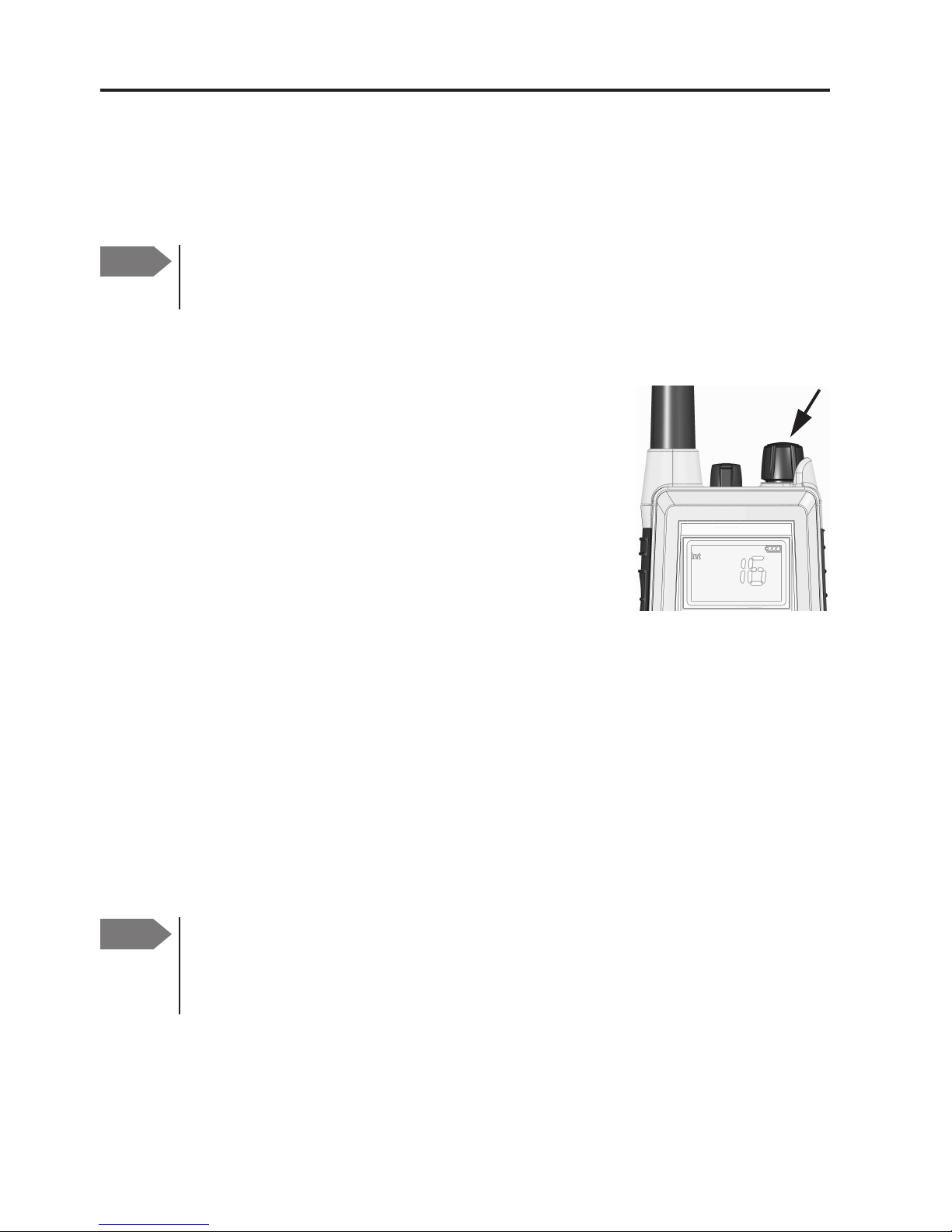
• Turn the knob at the top of the radio clockwise. The display lights up
showing the last used channel and the battery level.
• Select channel 16 (Distress or Safety), press the 16/C key.
• Press the PTT and say:
— “MAYDAY, MAYDAY, MAYDAY”,
— “This is”..... ships name repeated three times
—
— “MAYDAY”
— “This is”..... ships name and call sign,
— The ship’s position in latitude and longitude or other reference
to a known geographical location,
— The nature of distress and assistance wanted,
— Any other information which might facilitate the rescue.
— “OVER”
• Release PTT and listen for answer.
0709

i
SP3515 VHF
Document number: TT 98-124293-J
Release date: September, 2011
Copyright: © 2008 Thrane & Thrane A/S. All rights reserved.
Trademark Acknowledgements
• SAILOR is a registered trademark of Thrane & Thrane A/S.
• Other product and company names mentioned in this manual may be
trademarks or trade names of their respective owners.
Warranty limitation
IMPORTANT - The radio is a sealed waterproof unit. To create and maintain its
waterproof integrity it was assembled in a controlled environment using special
equipment. The radio is not a user maintainable unit, and under no circumstances
should the unit be opened except by authorized personnel. Unauthorized opening
of the unit will invalidate the warranty.
Disclaimer
Any responsibility or liability for loss or damage in connection with the use of this
product and the accompanying documentation is disclaimed by Thrane & Thrane.
The information in this manual is provided for information purposes only, is
subject to change without notice, may contain errors or inaccuracies, and
represents no commitment whatsoever by Thrane & Thrane. This agreement is
governed by the laws of Denmark.
Manuals issued by Thrane & Thrane are periodically revised and updated. Anyone
relying on this information should satisfy himself/herself as to the most current
version. Providers with access to Thrane & Thrane's Extranet may obtain current
copies of manuals at: http://extranet.thrane.com
Thrane & Thrane is not responsible for the content or accuracy of any translations
or reproductions, in whole or in part, of this manual from any other source.
1139

ii
Precautions
Avoid water and salt in the I/O connector and keep it
clean frequently.
Only use original Thrane & Thrane battery packs. Make
sure they are clean and dry before attaching the
transceiver. Be careful not to damage any gaskets.
Only use the original Thrane & Thrane charger for the
rechargeable battery.
Be very careful when handling the Lithium batteries.
With correct use they are safe but any misuse might
cause dangerous situations.
Never short circuit the battery terminals, never expose
the transceiver and the batteries to extreme temperature
or fire and never use any kind of violence.
Avoid close contact between the antenna and parts of
the human body. The top of the antenna must never be
closer than 5 cm to the body when transmitting.
Do not submerge the transceiver more than 1 m for 30
minutes.
Keep the transceiver at least 0.3 m away from the
magnetic compass.
0709

iii
Training information
SAILOR SP3515 VHF is designed for "occupational use only". It must be operated by
licensed personnel only.
The SP3515 complies with the FCC RF exposure limits for "Occupational Use Only".
• FCC OET Bulletin 65 Supplement C, evaluating compliance with FCC guidelines
for human exposure to radio frequency electromagnetic fields.
• American National Standards Institute (C95.1) IEEE standard for safety levels
with respect to human exposure to radio frequency electromagnetic fields,
3 kHz to 300 GHz.
• American National Standards Institute (C95.3) IEEE recommended practice for
the measurement of potentially hazardous electromagnetic fields - RF and
microwaves.
Correct use
For best performance, hold the radio vertically and 10 cm away from the head
when talking into the microphone.
Warning! Your Thrane & Thrane VHF radio generates
electromagnetic RF (radio frequency) energy when
transmitting. To ensure that you are not exposed to excessive
amounts of energy and thus to avoid health hazards from
excessive exposure to RF energy, all persons must be at least 5
cm away from the antenna when the radio is transmitting.
0703

iv
0641

v
Contents
Chapter 1 Introduction
Your VHF .............................................................................1
Performance .......................................................................2
Channels ............................................................................2
Chapter 2 Operation
Controls ..............................................................................5
Keys and buttons ................................................................5
The display .........................................................................7
Using the VHF .....................................................................8
Basic functions ...................................................................8
Other functions .................................................................. 11
Chapter 3 Batteries
Battery level indication ......................................................15
Removing and inserting the battery pack ...........................15
The battery charger ...........................................................16
Installing the charger ........................................................16
Recharging the battery ......................................................17
Chapter 4 Configuring the radio
Configuration mode ...........................................................19
Entering and using configuration mode ............................19
List of configuration settings .............................................20
0703

vi
Chapter 5 Equipment and accessories
External equipment .......................................................... 27
List of equipment .............................................................. 27
Connecting external equipment ........................................ 27
Impact on radio operation ................................................28
Accessorie connector ........................................................28
Accessories ......................................................................29
List of accessories .............................................................29
Attaching and removing the belt clip .................................31
Attaching the lanyard ........................................................31
Chapter 6 Troubleshooting
Displaying errors ..............................................................33
App. A Technical specifications
Technical data SP3515 ......................................................35
General ............................................................................35
Transmitter .......................................................................36
Receiver ...........................................................................36
Battery life guidelines ......................................................38
Dimensional drawing, transceiver ....................................39
Dimensional drawing, chargers .......................................40
Declaration of Conformity ..................................................41
App. B Attention
Goretex Membran ............................................................ 43
0740

Chapter 1
1
Introduction
Your VHF
The SP3515 VHF is designed for flexibility in daily
use. It connects easily to external equipment like
headsets and fist mikes, making the SP3515
suitable for any noisy environment.
Main features:
Unique man machine interface, an excellent
grip even with gloves, and large tactile
buttons.
Display with red adjustable backlight which
makes the display visible even at night.
Built-in “sleep” function, minimizing power
consumption and improving battery lifetime.
Selectable 12.5 kHz narrow band or 25 kHz
wide band operation.
Scrambling function for privacy calls.
CTCSS function for selective opening of
Squelch.
A lanyard and belt clip included.
A huge accessory program comes with the
SAILOR SP3500 series.
Please find the nearest SAILOR distributor on
www.thrane.com.
0643

Introduction
2
Performance
For best performance of the transceiver keep the following in mind:
• Keep clear of metal environment.
• Hold the transceiver vertically and 10 cm from lips and push the PTT
when transmitting.
• In receive mode carry the transceiver vertically with belt clips.
• To preserve battery power, adjust squelch to close the loudspeaker
when there is no signal.
• If you are in a lifeboat keep the antenna as high as possible.
Channels
This radio operates default with the following channel designators (see
also
ITU-R M.1084-4), depending on the configuration (see the notes on
the next pages):
19172560687785 US W-ch. CA W-ch.
2 10182661697886 W1 W8 W1
311192762717987 W2W9 W2
412202863728088 W3W10 W3
51321 647381 W4
61422 657482 W5
71523 667583 W6
81624 677684 W7
0740

Introduction
3
Channel modes
The notes in the following sections list the channel restrictions that apply
for each channel mode.
For information on how to select a channel mode, see
Entering and using
configuration mode
on page 19 and
CHAN
on page 20.
National frequency regulations shall always be respected and might
restrict
operation for this type of equipment.
International channels
Note:
Tx power is limited to 1 W on channels 75 and 76.
US channels
Notes:
• Tx power is limited to 1 W on channels 13, 67 and 77.
• The channels 2, 4, 60, 61, 62, 75 and 76 cannot be selected.
• The Weather channels (US W-ch. in the channel table) can only be
used in Rx direction.
• Channel 15 can only be used in Rx direction. Tx direction is blocked.
• The channels 1, 3, 5, 7, 18, 19, 21, 22, 23, 63, 64, 65, 66, 78, 79, 80, 81,
82 and 83 may only be used as simplex channels (and is marked A).
Channel 20 may be used as semi-duplex and simplex as 20A.
0740

Introduction
4
Canadian channels
Notes:
• Tx power is limited to 1 W on channels 15, 17, 20, 65, 66 and 77.
• The channels 19, 22, 63, 75, 76 and 81 cannot be selected.
• The Weather channels (CA W-ch. in the channel table) can only be
used in Rx direction.
• The channel 21 can only be used in Rx direction, marked 21B. Tx
direction is blocked.
• The channels 4, 5, 7, 18, 19, 21, 22, 61, 62, 64, 65, 66, 78, 79, 80, 81 and
82 may only be used as simplex channels (and marked A). Channel 83
may be used as semi-duplex and simplex as 83A.
Inland Waters (BI) channels
Notes:
• Tx power is limited to 1 W on channels 15 and 17.
• ATIS function is enabled on all channels.
• Dual watch and Scanning modes are disabled.
ATIS is automatically transmitted after each transmission in Inland
Waters. See
ATIS
on page 22 for information on how to program the call
sign.
0740
Chapter 2
5
Operation
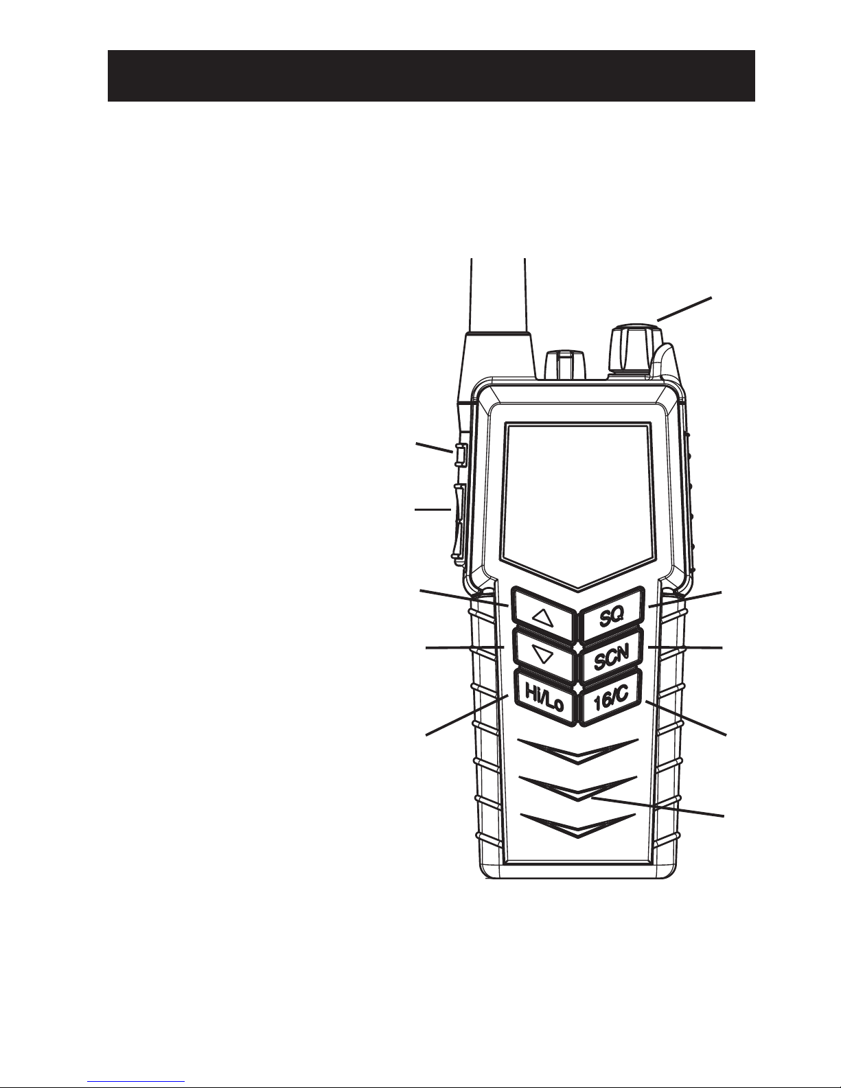
Controls
Keys and buttons
1. On/off/volume
2. Light/Lock
3. Push To Talk (PTT)
4. Up key
5. Down key
6. Hi/Lo output power
7. S qu e lc h
8. Scan
9. Priority channel (16)/
Call channel
10. Loudspeaker/microphone
1
2
3
4
5
6
7
8
9
10
0831
Operation
6
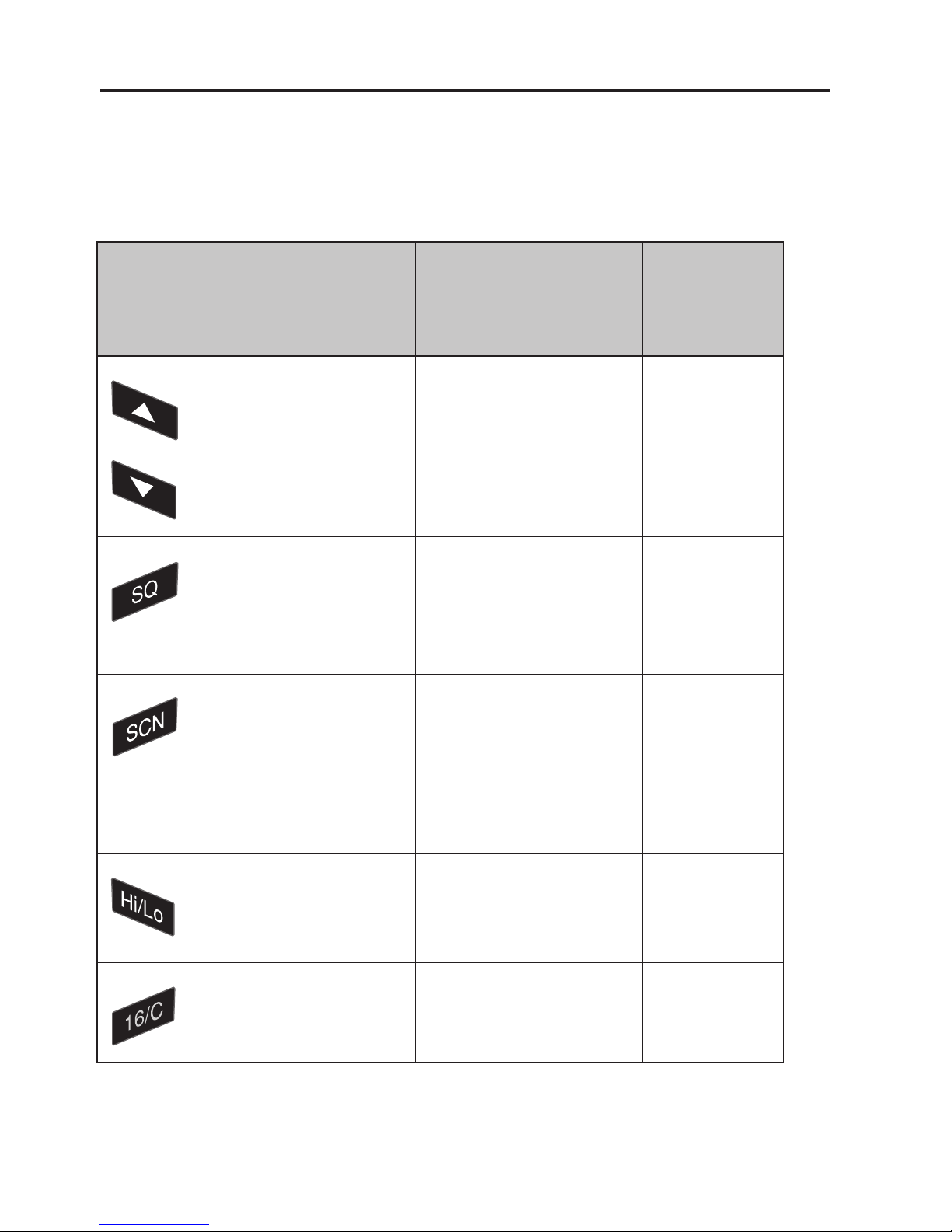
Key presses
Pressing and holding certain keys gives access to additional functions,
shown in the table below.
Key
Short press
(1 beep)
Long press
(2 beeps)
Extra long
press
(3 beeps)
Show next available
item in the list (up or
down).
Default: Channel
selection
Run through available
items, or
select tagged channels
A (
T) or B (S).
Run through
available
items if an A
or B channel
is tagged
Activate Squelch
control (Adjust with
up/down arrows).
Monitor function. Open
Squelch completely.
Set period of time in
configuration mode.
1 press: Activate/
terminate Dual/Triple
watch.
2 presses: Activate
memory scan.
Add/Delete channel
from memory scan.
Toggle between high
and low transmitter
power.
Select channel 16. Select programmed
Call channel.
Program Call
channel.
0703
Operation
7
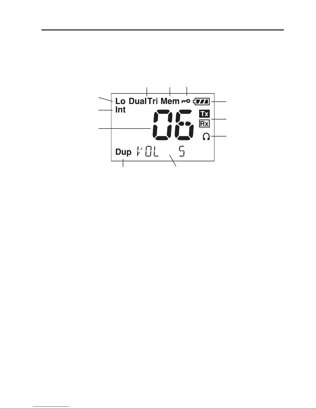
The display
The display holds various fields of information, explained below.
1. Current working channel.
2. Current channel mode.
3. “Lo”: Reduced transmitter power.
Full transmitter power is not shown in display.
4. Dual/Triple watch activated.
5. Current working channel is marked for scanning.
6. Keypad is locked.
7. Battery level indicator.
8. Transmitting (Tx) /Receiving (Rx).
9. Accessory is connected.
10. Service line for various purposes. In this example the volume level.
11. Semi-duplex channel.
1
3
456
7
8
9
10
2
11
0740
Operation
8
Using the VHF
Basic functions
Switching the radio on and off
• To switch the radio on, turn the knob at the top
of the radio clockwise.
The display lights up showing the last used
channel and the battery level.
• To switch the radio off, Turn the knob back
counter-clockwise until it clicks.
Selecting the working channel
• To select channel 16 (Distress or Safety), press the 16/C key.
• To select the Call channel, use a long press on 16/C.
• To select among all available channels, press S or T on the keypad.
For fast selection, press and hold S or T.
The display shows the currently selected channel. The bottom left corner
of the display shows “Dup” if the channel is a semi-duplex channel.
Note Before using the radio, mount the antenna at the top of the
radio. The antenna is delivered with the radio.
Note Long press on S or T can also be used to select preferred
channels. For information on how to program preferred
channels, see
Configuring the radio
on page 19.
0740
Operation
9
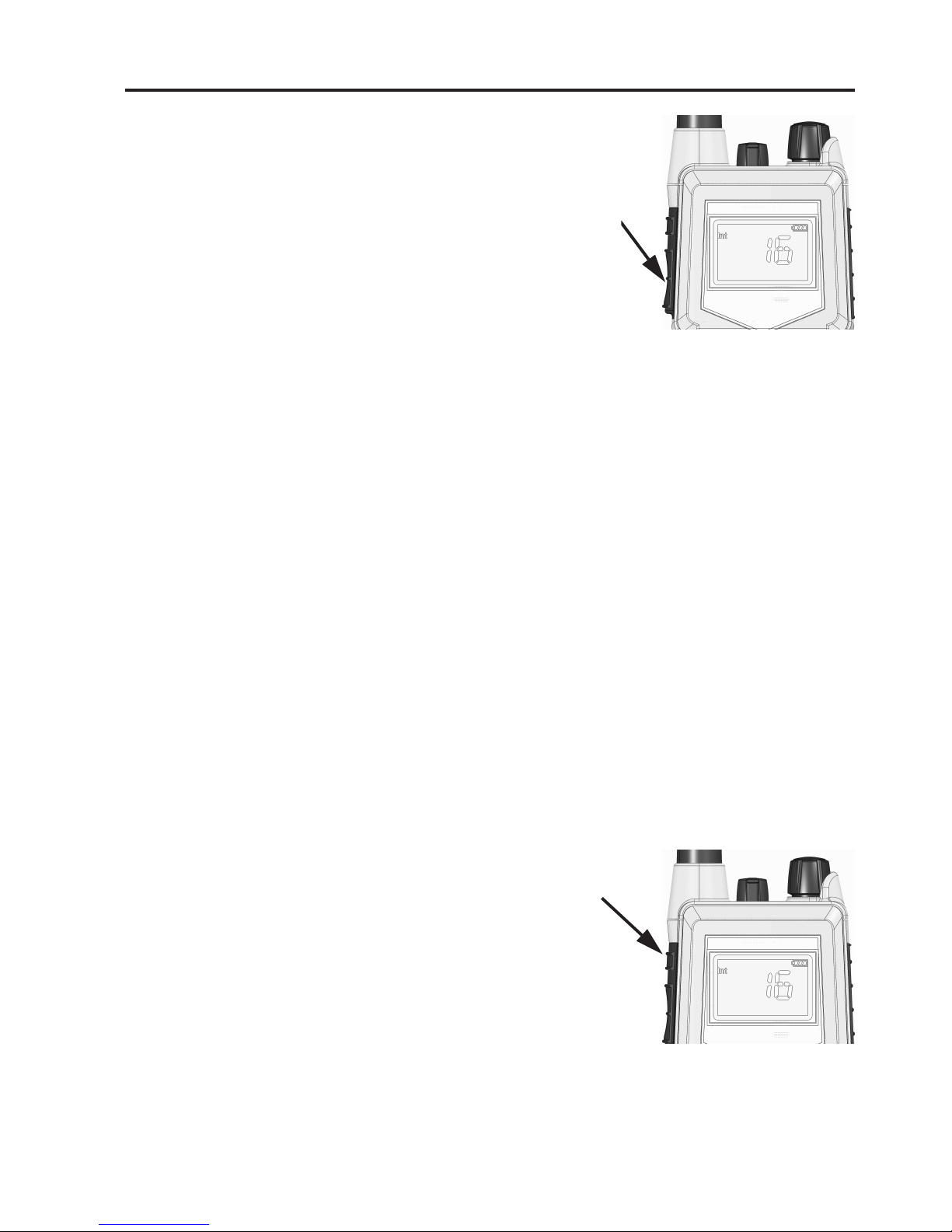
Activating a call
To activate a call to the selected channel, press and
hold the PTT button on the side of the radio.
The radio transmits as long as the PTT button is
pressed. A small Tx sign next to the channel number indicates when the radio is in transmit mode.
Adjusting the volume
• To increase the volume, turn the on/off knob at the top of the radio
clockwise.
• To decrease the volume, turn the knob counter-clockwise.
The display shows the level of the volume, e.g. “VOL 5”, while it is
adjusted.
Using Squelch control
• To activate Squelch control, press the SQ key.
• To set the Squelch level, press S (closing) or T (opening). The
display shows the Squelch level while it is adjusted, e.g. “SQ 5”.
Adjusting the display backlight
• To turn on the backlight, press the
Light/Lock button on the side of the radio.
• To adjust the backlight level, press S or T
within 3 seconds after turning on the light.
The display shows the level while it is
adjusted, e.g. “DIM MED”.
0703
 Loading...