

Page 1
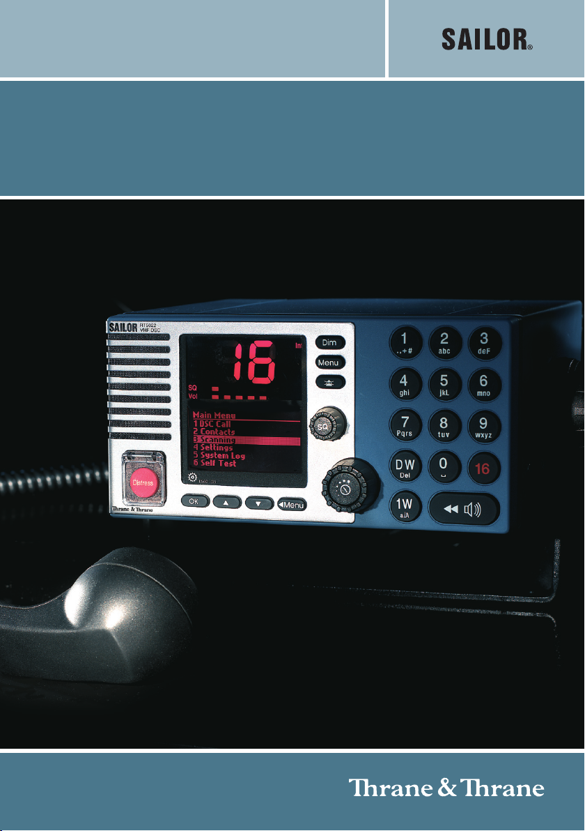
OPERATION MANUAL
SAILOR RT5022 VHF DSC
SAILOR RT5020 VHF DSC Duplex
Page 2

Page 3

Introduction
Congratulations on your new SAILOR RT5022/RT5020 VHF.
SAILOR marine equipment is specially designed for the extremely rugged conditions on
board a ship, based on more than 50 years of experience with all kinds of vessels, from
small pleasure crafts, over fishing vessels working under all climatic conditions, to the
biggest ships.
SAILOR
equipment - a position which has been maintained by means of constant and extensive
product development. We have a worldwide network of distributors with general agencies in
more than 80 countries. All our distributors are specially trained to service all your SAILOR
products.
About this manual
This manual is for the daily user of the system. Additionally, it includes a section on the
installation procedures, and - on page iii - standard distress procedures. We highly recom-
mend you to read the manual before you start using the equipment.
Notice: There may be some minor differences in the graphic layout of the product in the
manual compared to the actual physical unit.
Abbreviations used in this manual
ADDR Address
BI Channel mode when sailing on European rivers
BQ DSC Call Acknowledgement Reply
CU Control Unit
DSC Digital Selective Calling
DW Dual Watch
EOS DSC End Of Sequence
GMDSS Global Maritime Distress and Safety System
MMSI Maritime Mobile Service Identification
PTT “Push To Talk” button
RQ DSC Call Acknowledgement Request
RX Receive/r
SQ Squelch
TX Transmit/ter
UTC Universal Time Coordinated
®
is one of Europe’s leading manufacturers of maritime radio communication
®
Please note
Any responsibility or liability for loss or damage in connection with the use of this product and
the accompanying documentation is disclaimed. The information in this manual is provided
for information purposes only, is subject to change without notice, may contain errors or
inaccuracies, and represents no commitment whatsoever. This agreement is governed by
the laws of Denmark.
Doc. No.: B5022GB0 Issue: H/0622
0622
i
Page 4

Training Information
The Thrane & Thrane RT5022/RT5020 VHF radio is designed for “occupational use only”
and is also classified as such.
It must only be used in the course of employment by individuals aware of both the hazards
as well as the way to minimize those hazards.
The radio is thus NOT intended for use in an uncontrolled environment by general public.
The RT5022/RT5020 has been tested and complies with the FCC RF exposure limits for
“Occupational Use Only”. The radio also complies with the following guidelines and
standards regarding RF energy and electromagnetic energy levels including the
recommended levels for human exposure:
• FCC OET Bulletin 65 Supplement C, evaluating compliance with FCC guidelines for
human exposure to radio frequency electromagnetic fields
•
American National Standards Institute (C95.1) IEEE standard for safety levels with
respect to human exposure to radio frequency electromagnetic fields, 3 kHz to 300 GHz
• American National Standards Institute (C95.3) IEEE recommended practice for the
measurement of potentially hazardous electromagnetic fields – RF and microwaves
Below the RF exposure hazards and instructions in safe operation of the radio within the
FCC RF exposure limits established for it are described.
Warning:
Your Thrane & Thrane radio set generates electromagnetic RF (radio frequency) energy
when it is transmitting. To ensure that you and those around you are not exposed to
excessive amounts of that energy (beyond FCC allowable limits for occupational use) and
thus to avoid health hazards from excessive exposure to RF energy, FCC OET bulletin 65
establishes an Maximum Permissible Exposure (MPE) radius of 3” (0.9m) for the maximum
power of your radio (25W selected) with an half wave omni-directional antenna having a
maximum gain of 3 dB (5.2dBi). This means all persons must be at least 3” (0.9m) away from
the antenna when the radio is transmitting.
Installation:
1. An omni-directional antenna with a maximum power gain of 5.2 dBi must be mounted at
least 9.6” (2.9m) above the highest deck where people may be staying during radio
transmissions. The distance is to be measured vertically from the lowest point of the
antenna. This provides the minimum separation distance which is in compliance with RF
exposure requirements and is based on the MPE radius of 3” (0,9m) plus the 6.6” (2m)
height of an adult.
2. On vessels that cannot fulfil requirements in item 1, the antenna must be mounted so
that its lowest point is at least 3” (0.9m) vertically above the heads of people on deck and
all persons must be outside the 3” (0.9m) MPE radius during radio transmission.
• Always mount the antenna at least 3” (0.9m) from possible human access
• Never touch the antenna when transmitting
• Use only authorized T&T accessories
3. If antenna has to be placed in public areas or near people with no awareness of the radio
transmission, the antenna must be placed at a distance not less than 6” (1.8m) from
possible human access.
Failure to observe any of these warnings may cause you or other people to exceed FCC RF
exposure limits or create other dangerous conditions.
ii
0611
Page 5
Quick DSC distress call
(only for emergency use)
1. If necessary, switch on by pressing the ON/OFF button
2. Lift up the lid covering the orange key and press for 5 seconds.
3. The Alarm indicator light will flash and will be accompanied by a sound. Distress
message is sent at the continuous tone.
4. Unless stopped manually, by pressing the
distress call is automatically repeated every 3½-4½ minutes until distress acknowledg-
ment is received.
Wait for distress acknowledgement and start mayday procedure. If an alarm panel is
connected the VHF DISTRESS button on this unit will have the same functionality. All further
handling should continue in front of your main VHF DSC.
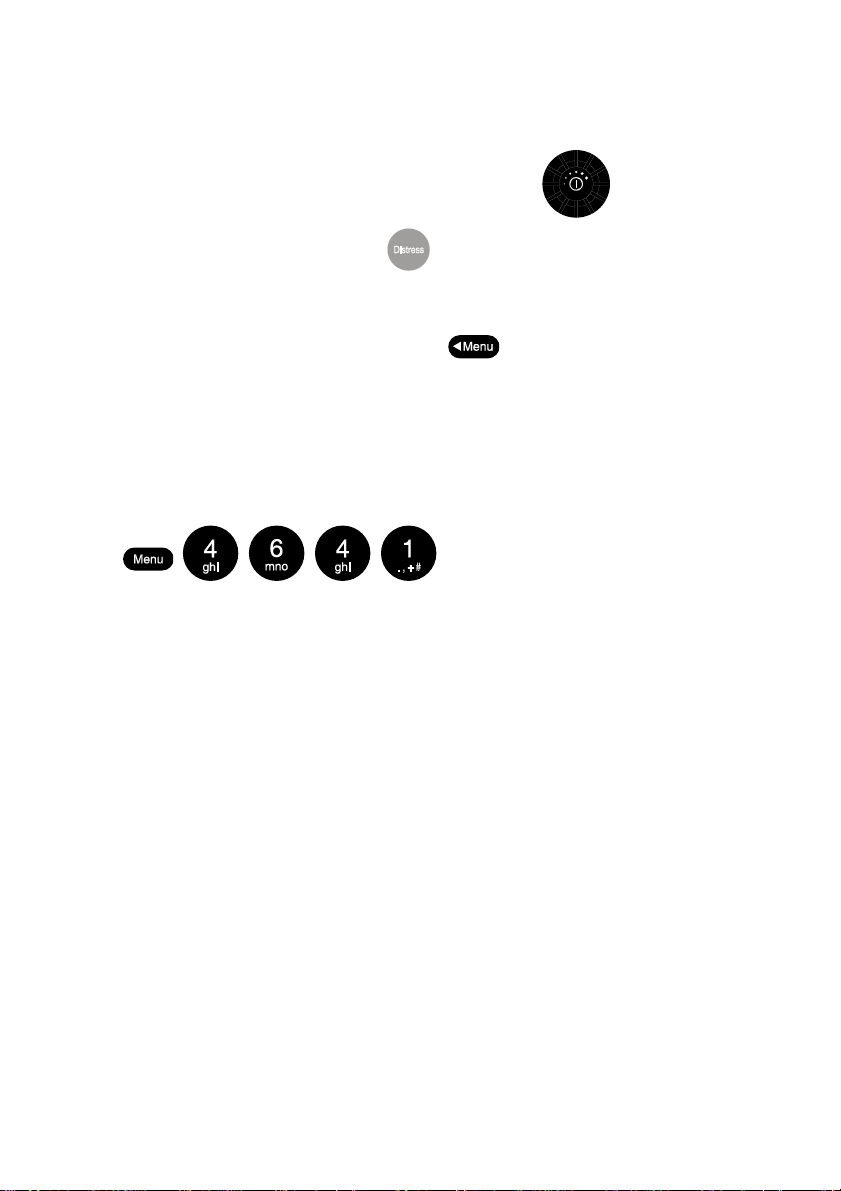
NOTE: If needed the default language (English) is obtained by pressing the following keys:
key or switching the unit off, the
Mayday procedure
When DSC distress acknowledgement is received after you have pressed DISTRESS, or if
you otherwise need to commence distress traffic via radiotelephony on the distress traffic
frequency channel 16, follow this procedure:
• “MAYDAY”,
• “this is”,
• the 9-digit identity
• the ship’s position in latitude and longitude or other reference to a known geographi
cal location,
• the nature of distress and assistance wanted,
• any other information which might facilitate the rescue.
Upon reception of a DSC distress alert from another ship in distress, you should acknowledge the receipt by radiotelephony on the distress traffic frequency channel 16, by doing the
following:
and
the call sign or other identification of the ship,
• “MAYDAY”,
• the 9-digit identity of the ship in distress, repeated 3 times,
“this is”,
• the 9-digit identity or the call sign or other identification of own ship, repeated 3times,
• “RECEIVED MAYDAY”.
0611
iii
Page 6
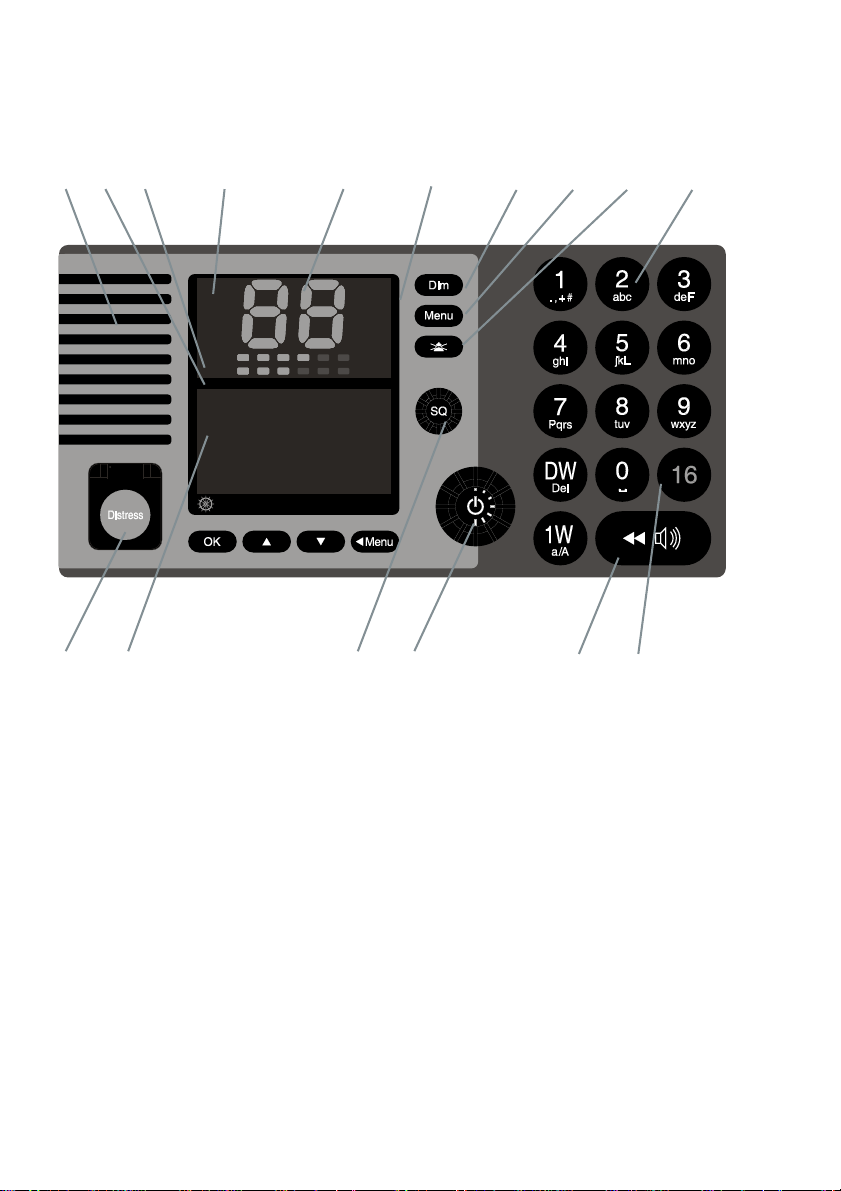
Your VHF at a glance
(RT5020/RT5022)
1 2 3 4 5 6 78910
Alarm
Call
DW
1W
SQ
Vol
0191 - 05
Int
US
BI
Tx
11 12 13 14 15 16
1. Loudspeaker
2. Volume level indicator
3. Squelch level indicator
4. Indicator lamps. Condition when lit:
1W: 1 watt transmission mode.
Alarm: Alarm call received.
Call: DSC call for you received.
DW: Dual watch mode
5. Telephone display
6. Indicators. Condition when lit:
Tx: Transmitting
Int: International channel system
activated
(Is used when sailing on any sea in the
world except in US waters)
US: US channel system activated
(Is used when sailing in US Waters)
BI: BI channel system activated
(Is used when sailing on the rivers of
Europe)
7. Dimming button
8. Menu button
9. Mute alerts
10. Keyboard.
11. DISTRESS button (Lid with spring.
Normal push button underneath)
12. Information/Message display
13. Squelch control. Adjust to silent when no
station is received
14. ON/OFF / VOLUME control
15. Replay button
16. Quick-selection key for channel 16.
iv
0611
Page 7

Contents
Introduction ............................................................................................................................... i
About this manual ................................................................................................................. i
Abbreviations used in this manual ....................................................................................... i
Training Information................................................................................................................ ii
Quick DSC distress call.......................................................................................................... iii
Mayday procedure................................................................................................................... iii
Your VHF at a glance (RT5020/RT5022) ................................................................................ iv
1 Radio communication in brief.......................................................................................... 3
1.1 Powering VHF............................................................................................................. 3
1.2 Operating VHF radio communication ......................................................................... 3
1.3 Receiving a call on Channel 16.................................................................................. 3
1.4 Making a radiotelephone call...................................................................................... 4
1.5 Speaker volume .......................................................................................................... 4
1.6 Earpiece volume ......................................................................................................... 4
1.7 Squelch ....................................................................................................................... 4
1.8 Channel selection ....................................................................................................... 5
1.9 Dual watch .................................................................................................................. 5
1.10 Replay ......................................................................................................................... 5
1.11 Dimming ...................................................................................................................... 6
1.12 Contrast....................................................................................................................... 6
2 Basic DSC operations ....................................................................................................... 7
2.1 Menu operation ........................................................................................................... 7
2.2 Receiving a DSC call.................................................................................................. 7
2.3 Transmitting DSC Calls .............................................................................................. 8
2.4 Call a ship station ....................................................................................................... 8
2.5 Call a shore station ..................................................................................................... 8
2.6 Direct call to a PSTN via a coast station.................................................................... 8
2.7 Call a group of ships ................................................................................................... 8
2.8 Create emergency calls.............................................................................................. 9
2.9 DSC call log ................................................................................................................ 9
3 Your VHF in detail ............................................................................................................ 10
3.1 Abnormal power-down.............................................................................................. 10
3.2 Settings ..................................................................................................................... 10
3.3 Automatic squelch programming.............................................................................. 10
3.4 Setting channel mode ............................................................................................... 11
3.5 Private channels ....................................................................................................... 11
3.6 Duplex channels ....................................................................................................... 11
3.7 ATIS (inland waterways only)................................................................................... 12
3.8 Transmitter power ..................................................................................................... 12
3.9 Channel scanning ..................................................................................................... 13
3.10 Creating scan tables ................................................................................................. 13
0611
1
Page 8

4 DSC operations in detail ................................................................................................. 14
4.1 MMSI Number ........................................................................................................... 14
4.2 Group MMSI number ................................................................................................ 15
4.3 Differentiating incoming calls by ringing tones ........................................................ 15
4.4 Working channel ....................................................................................................... 16
4.5 Contact list ................................................................................................................ 16
4.6 Settings for DSC ....................................................................................................... 18
4.7 Implicit behaviour for operations with DSC.............................................................. 19
4.8 Radio configuration and settings .............................................................................. 21
4.9 Voice scrambler ........................................................................................................ 22
4.10 Automatic conditions................................................................................................. 23
4.11 Software releases ..................................................................................................... 23
5 Errors and warnings........................................................................................................ 25
5.1 System event logging ............................................................................................... 25
5.2 Troubleshooting ........................................................................................................ 25
6 Menu tree .......................................................................................................................... 29
7 Optional functional devices ........................................................................................... 31
7.1 Semi-functional control unit ...................................................................................... 31
7.2 Alarm panel ............................................................................................................... 35
7.3 Printer........................................................................................................................ 36
8 Maritime Channels ........................................................................................................... 37
8.1 International channels............................................................................................... 37
8.2 US channels.............................................................................................................. 38
8.3 BI channels ............................................................................................................... 39
8.4 CA channels.............................................................................................................. 40
9 Installation ........................................................................................................................ 41
9.1 Mounting possibilities ............................................................................................... 41
9.2 Compass safe distance ............................................................................................ 47
9.3 Interface connections ............................................................................................... 48
9.4 Power supply ............................................................................................................ 55
9.5 Antenna installation and precautions ....................................................................... 55
10 Technical specifications ................................................................................................. 57
10.1 General information .................................................................................................. 57
10.2 General DSC facilities .............................................................................................. 57
10.3 Specific data for transceiver unit RT5022................................................................ 57
10.4 Specific data for transceiver unit RT5020................................................................ 58
2
0622
Page 9
1 Radio communication in brief
1.1 Po wering VHF
The VHF is turned on by a single press on the ON/OFF/Volume button. The VHF
is turned off by pressing the ON/OFF/Volume button for 3 seconds.
Always indicated by a count down window in the information display, except if the
radio is powered down in distress mode.
Any connected devices (Alarm Panel, Handset, CUs) will be operational only if
the VHF is powered.
1.2 Operating VHF radio communication
The VHF is operated by means of a handset.
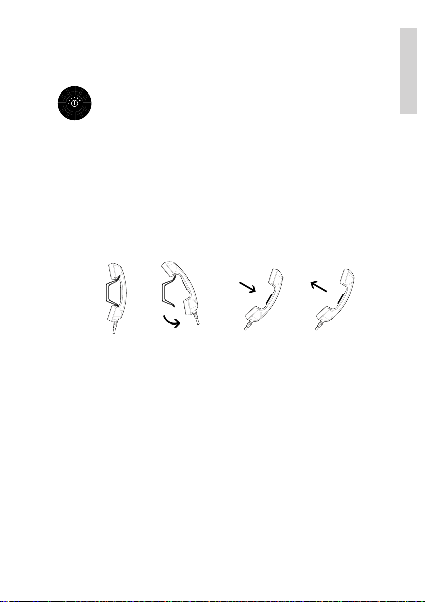
To bring the VHF in transmission mode the handset must be hooked off and the PTT button
on the handset has to be pressed. Transmission is indicated by the lighted TX indicator.
Receive mode is always reached by releasing the PTT button.
HandsetHandset
hooked on
Transmit and receive is performed on the working channel shown in the telephone display.
If the handset is used with an RT5020 duplex radio, received signal can always be monitored
in the handset earpiece. With the RT5022 simplex/semi-duplex radio the received voice
signal can only be monitored in the earpiece while PTT is released.
hooked off
Press PTT
PTT
Release PTT
PTT
Basic
1.3 Receiving a call on Channel 16
When you hear your call name in the loudspeaker:
1. Lift the handset.
2. Press the PTT key.
3. Repeat the name of the station calling you and say “This is [your ship’s name].”
4. Suggest a channel other than 16 by saying “Channel [suggested number]”.
5. Say “Over” and release the PTT key
to allow your caller to confirm the suggested new channel.
0544
3
Page 10

6. Switch to the new channel – for example, channel 71
– and begin your conversation. Press PTT only when you are talking. If you are on a
simplex channel (in other words, a channel that can carry only one transmission at a
time), always say “Over” just before releasing. With duplex channels (ship-shore
calls), the conversation can be two-way as with a normal land telephone calls.
Basic
1.4 Making a radiotelephone call
A radiotelephone call is preferably to be commenced using DSC. Alternatively the following
public calling procedure shall be used:
1. Select channel 16 (by pressing
2. Lift the handset.
3. Press the PTT key and make your call.
First, say the name of the station
you are calling three times.
Then say “This is [your ship’s name”], again three times.
Finally, say “Over”.
4. Release the PTT key to listen.
5. When answered, agree upon a channel,
switch to that channel – for example, channel 6 – and begin your conversation. Press
PTT only when you are talking. If on a simplex channel (in other words, a channel
that can carry only one transmission at a time), always say “Over” just before
releasing.
) or other agreed channel.
1.5 Speaker volume
The volume in the loudspeaker (internal and optional external) is adjusted by turning the
VOLUME control. The volume level is visualized in the telephone display. The volume can be
adjusted to a mute mode by turning the volume control left (down). If the volume is adjusted
to the mute level the VOL LED will flash.
1.6 Earpiece volume
The volume level of the default handset earpiece is adjusted by selecting the Handset
Volume menu (4.3.1).
The
information/message display.
and buttons are used to adjust the level. The level is indicated in the
1.7 Squelch
The squelch level is adjusted by using the squelch control. The actual squelch
level is visualized in the telephone display.
4
0544
Page 11
1.8 Channel selection
The system is defaulting to channel 16 after a normal power-on.
Channels can be selected using the
(increasing to next valid VHF channel) or
(decreasing channel). Channels can also be entered using the numeric keypad.
The active working channel is always shown in the upper display.
1.9 Dual watch
Dual watch is a mode where the priority channel (16) is scanned periodically for
a signal while listening on a working channel.
Dual watch is activated by pressing the DW button.
The DW indicator is lit while DW is active. Dual watch is deactivated by:
• Pressing DW – Continues to receive on the working channel.
• Pressing PTT – Transmits always on working channel
• Pressing ´16´.
• Pressing Replay - Dual watch is terminated while the message is replayed
and will then be re-invoked
Selecting a new channel while in dual watch mode will continue dual watch on the new
selected working channel, unless a signal is found on channel 16.
1.10 Replay
Replay is a facility built into the product which always will allow the operator to repeat the
latest 90 seconds of received voice data to be replayed in the acoustic devices.
Received voice data is defined when the squelch is open. This means that 90 seconds of
actual traffic could be accumulated over several hours/days.
Basic
If the 90 seconds storage limit is reached the oldest data is simply overridden with the
newest received traffic data (FIFO principle).
Activating replay
The front panel has a dedicated replay button.
A push on the replay button will bring up a (replay) window in the
information/message display. Holding down replay will drive a
counter to be updated in the display where it is determined how many
seconds of recorded data is wanted for replay - the last XX seconds
of recorded data.
If pressing the replay button in normal receive mode this will still allow the unit to receive
audio in the speaker system.
0544
5
Page 12

When releasing the replay button the replay function will take over the audio system and
start to replay the last XX seconds of data received on any channel. The time when the traffic
was received and the channel on which it was received is displayed during replay.
Volume control can be used on the replay data to adjust sound pressure in audio devices.
Basic
During replay “— —” is shown in the channel display, to indicate that listening on the live
receive signal is disabled in this situation (as well as recording is disabled). If a signal is
received on the working channel while replay is activated, this is indicated in the lower left
corner of the replay window.
Replay is interrupted when:
• Pressing
• Pressing PTT
• Receiving any message in the information/message display
, or
Recorded voice data will not survive power-down of any kind
.
1.11 Dimming
To adjust the light intensity the dim button is pressed.
While the dim button is pressed the intensity is changing. Releasing the dim
button will maintain the current light intensity.
A renewed pressing of the dim button will change the direction of the light intensity change.
If the VHF is dimmed to zero, any key press will wake up the light to a minimum visible at
night. Active text in the information/message display might prevent dimming to zero.
It is possible to reduce illumination to zero. If you press a key in this state the light will
illuminate to the lowest illuminated state for 5 seconds, where after it will return to the zero
illumination state. If a message is shown on the screen while dimming is set to zero, the
illumination is adjusted to the lowest nonzero value.
1.12 Contrast
Contrast of the information/message display (and thereby optimizing the vertical viewing
angle) can be adjusted initially by entering the Display Contrast menu. Use the arrows to
adjust contrast. The contrast will be set simultaneously during adjustment.
6
0544
Page 13
2 Basic DSC operations
When switched on, your VHF automatically monitors channel 70 for incoming DSC calls.
2.1 Menu operation
To operate DSC functionality the menu system is used. The main menu can be activated by
pressing . From the main menu all parts of the menu tree can be reached (see
chapter: Menu tree).
All menus have a unique hierarchical number. The main menu is the only menu which does
not have a number. The number is (to a certain level) displayed in the upper right corner of
the screen. If more than 6 items are available in the menu, arrows will indicate if remaining
items are to found above (
items.
The active menu item is highlighted. A press on
A press on
A press on any of the numeric keys (1 to 9) in a menu will quickly select the menu item
having the corresponding number.
A press on
is pressed in the main menu, the menu will be turned off.
Selecting the menus for transmitting DSC calls will lead to a sequence of windows (flows).
The flow sequences are controlled by the
(cancel and return to the previous window) buttons.
Following a menu hierarchy or a window flow might include a guidance text (e.g. “OK/next”
). Certain windows and lists do not show any guidance texts. These windows can
always be left by
window).
will select the item which is currently in focus.
will return to the previous menu window (normally one level up). If
(jumping to main menu) or (returning to the previous
) current items or below ( ) current displayed menu
or will move the focus.
(accept and proceed to next window) or
Basic
2.2 Receiving a DSC call
An incoming call will always be recognized by activity on the CALL indicator – and if more
severe (Distress and Urgency calls), also the ALARM indicator. When receiving a DSC call
the message will be displayed immediately in the information/message display, if not
obstructed by any other operations taking place. Received DSC calls will always be accompanied by a sound alarm.
When you receive a call you can read in the display whether the call is addressed to All
Ships, ships in a specific geographic area, a group of ships or to your ship (identified by your
MMSI number) as an individual call.
0544
7
Page 14
If you are busy you can choose to handle the call a little later (e.g. by pressing ),
which will stop the alarm sound.
When you are ready to accept the call, lift the handset or press . Your choices
handling the particular call will now appear. Follow the instructions.
Basic
If an individual call is received it will not be acknowledged before you accept the call.
2.3 Transmitting DSC Calls
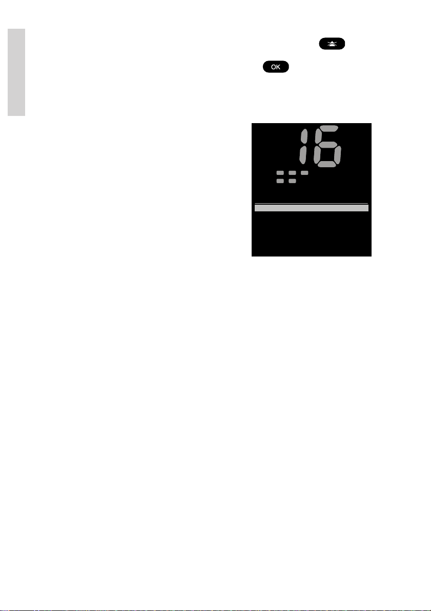
All DSC calls are initiated from the DSC Call Menu (1).
When entering a menu item, you will be guided through
the call construction. For every call generated you will
have the possibility of verifying the call before you
transmit it.
Alarm
Call
DW
1W
SQ
Vol
DSC Call
1 Station Call
2 PSTN Call
3 Group Call
4 Emergency
5 DSC Logs
Int
US
Tx
1
2.4 Call a ship station
To call a ship station and suggest a working channel, enter the Station Call menu (1.1) and
follow the instructions. Have the ships MMSI number ready if it is not available via the
contact list.
Please also refer to Section 4.1.2 for using extended sub-addressing.
2.5 Call a shore station
To call a shore station, enter the Station Call menu (1.1) and follow the instructions. Have the
shore MMSI number (00*) ready if it is not available via the contact list.
2.6 Direct call to a PSTN via a coast station
This kind of calls requires automatic/semi-automatic support from the coast station, and is
available only within some countries. If the service is not available, you will need to make a
simple shore station call and request the connection via radiotelephony.
BI
To make a direct phone call to a PSTN or a mobile phone, enter the direct phone call menu
(1.2) (PSTN Call) and follow the instructions. Have MMSI number (00*) for a reachable shore
station ready if it is not available via the contact list, as well as the public phone number you
would like to request.
2.7 Call a group of ships
To call a group of ships enter the Group Call menu (1.3) and follow the instructions. Have
the group MMSI number (0*) ready if it is not available via the contact list.
8
0544
Page 15
2.8 Create emergency calls
Emergency
1.4
2 Compose Urgency
5 Compose Distress Ack
3 Compose Safety
4 Compose Relays
1 Compose Distress
DSC Logs
1.5
2 DSC Receive Log
3 DSC Transmit
4 Printing
1 DSC Distress Log
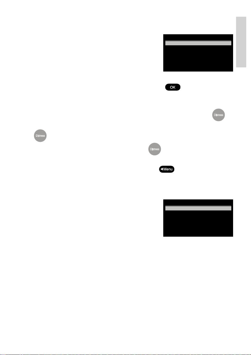
In the category of emergency calls (1.4) you will find the
following menu:
Transmitting any of these calls should be done with
caution. Please make yourself familiar to the common
procedures for using these calls.
Selecting any of the call types will lead to a call establishing flow with maximum flexibility.
You should make yourself familiar with the flow sequences, but be sure you do not actually
send the message by mistake. In other words, never press
tion window if you do not actually intend to send an emergency call.
Designated distress calls are composed entering the menu (1.4.1). From this list the Nature
of Distress is selected. A fast method to reach this selection list is a short press on .
The call completion is then continued from here. If no nature of distress is selected, but
is pressed for 5 seconds, an undesignated distress is sent.
Distress calls are always transmitted by pressing the button for 5 seconds. After you
have transmitted a distress call the VHF is in distress mode (distress call is re-transmitted
once each 3½-4½ minutes). The distress mode can be exited only by reception of the
appropriate distress acknowledgement call or if you press
power off the VHF. The VHF will start up in distress mode after a power failure.
the transmit verifica-
for 5 seconds, or if you
2.9 DSC call log
Received and transmitted DSC messages can be found
with details in the DSC Logs (1.5). A special log contains
distress related calls. The call log system will store the
last (20) calls sorted by date and time.
Basic
Each of the logs and each of the calls within the logs
have their own possible actions upon selection
(e.g. printing).
2.10 Entering your position into the system
Ship’s position and the time for this position are essential to the success of a possible rescue
operation. This information is automatically incorporated in a DSC distress call sent from the
VHF. Therefore it is important always to keep this information updated.
Normally a GPS is connected to the VHF, which ensures continued updating of position and
time.
If the VHF is not connected to an external GPS system, or a malfunction of the GPS
connection is detected by the VHF, the VHF will automatically prompt for manual update of
the position 1 minute after power-up and then every 4 hours. The position and time can
always be entered via the Set Position & Time selection in the Settings menu (4.1.1).
0605
9
Page 16

3 Your VHF in detail
3.1 Abnormal power-down
If for any reason the main power disappears for a period less than 10 minutes, the VHF will
be able to turn itself on when power is resumed (without pressing ON/OFF).
If the VHF was abnormally powered down for less than 1 minute, the VHF will start up with
the same settings as before the power failure took place (communication channel, volume,
squelch settings, etc.).
If the abnormal power down lasted more than 1 minute the VHF might start up with the
settings as they were last time the VHF was turned off normally.
Detail
3.2 Settings
All volume settings are stored as default during the power off sequence.
3.3 Automatic squelch programming
It is possible to attach a squelch level with each channel if particular noisy channels require
continuous special squelch setting. If a channel is selected squelch level is inherited from
either the global setting or a stored squelch level for that particular channel (default is that all
channels are using the global squelch level).
Storing squelch level on a channel is done while listening on that particular channel:
• Push the
• The squelch level is now automatically adjusted to suppress the noise on the
channel. While adjusting, noise is heard. The squelch level indicator follows adjustment, and finally display the required level. The squelch level is memorized on the
channel, indicated by flashing the SQ LED (flashing 3 seconds).
If a channel with a programmed squelch level is selected and the SQUELCH button is turned
the programmed squelch level for that channel is removed (global level).
During Dual Watch or Scanning only the global squelsh level is used (as indicated by the
squelch level indicator). Channel 16 squelch level is not programmable.
All programmed channel squelch levels are stored during power down and restored during
power-up sequence.
button.
10
0544
Page 17
3.4 Setting channel mode
The VHF is delivered from factory with both Int. & US channels enabled for selection from
the operation menu.
Provision of other country regions (channel tables) for selection requires the intervention by
an authorized Thrane & Thrane representative in order to enable such.
The operator selection of preferred country region (channel table) is done from menu 4.4.1
(channel mode) and the selected country region is indicated in the front panel display (note:
this does not apply to the CA channel table and any custom defined channel tables).
The selected country region is stored during power down sequence.
Using the country region BI (Inland waterways) Dual Watch (DW) and scanning mode are not
available.
3.5 Private channels
Private channels can be programmed by means of the service interface only (distributor/
dealer).
Programmed private channels become valid for selection on the front panel. Using the
/ will simply make the private channel number appear above the highest
numeric channel number. 30 (3x10) private channels are available for each enabled channel
mode. Note: In US mode private channels P0-9 will be pre-programmed with the 10 weather
channels. In CA mode, P0-2 is pre-programmed with the 3 regional weather channels.
Private channels can be selected using the numeric key pad:
Detail
• Private channels: Long press on
• Leisure channels: Long press on
• Fisher channels: Long press on
Continued activation of the keys ´3´, ´5´ or ´7´ will cause the letters F-, L- or P- respectively
to be displayed.
followed by a digit (0-9)
followed by a digit (0-9)
followed by a digit (0-9)
3.6 Duplex channels
If duplex channels are selected on an RT5022 simplex/semi-duplex radio (see chapter:
Maritime channels) the VHF will operate in semi-duplex mode meaning that the VHF is
operated in simplex mode, but uses two different frequencies to receive and transmit.
If a duplex channel is selected on an RT5020 duplex radio full duplex is supported on these
channels, meaning that both receiver and transmitter is active simultaneously.
0605
11
Page 18
3.7 ATIS (inland waterways only)
p
r
r
p
t
f
g
r
t
y
y
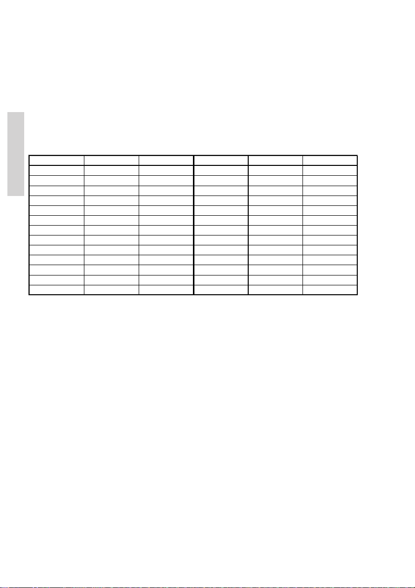
ATIS is mandatory to use in inland waterways on e.g. the Rhine. ATIS is a digital data
stream containing ships call sign coded into a DSC-like message, sent over the voice
channel each time the PTT button is released. If PTT is continuously pressed ATIS is
automatically sent each 5 minutes.
ATIS is enabled automatically when BI is selected in menu (4.4.1).
For purpose of operator comfort the received ATIS signal on the active voice channel will be
muted.
The ATIS call sign is programmable from the service interface or from menu 4.4.3. once.
The format of the programmed ATIS code is entered according to the following call sign
prefix conversion table:
Character Phonetic Value Character Phonetic Value
Detail
AAl
B Bravo 2 O Oska
C Charlie 3 P Pa
D D elta 4 Q Quebec 17
E Echo 5 R Romeo 18
FFoxtro
GGol
H H otel 8 U Uniform 21
I India 9 V Victo
JJuliet
KKilo11 XX-ra
L Lima 12 Y Yankee 25
M Mike 13 Z Zulu 26
I.e. a Dutch (MID-number 244) ship with call sign SP1234, should be programmed with the
following number:
ha 1 N Novembe
a16
6 S Sierra 19
7TTan
10 W Whiske
o20
14
15
22
23
24
244P1234
with the digit 2 entered as the first digit, and the digit 4 as the last digit.
3.8 Transmitter power
Transmitter output power can always be chosen while the radio is active. Pressing the 1W
button will toggle the transmitter power between low power (below 1W) and high power
(below 25W). The 1W indicator is lit when low power is selected. As a default any channel
shift will cause the transmitter power to be adjusted to the maximum power allowed on that
channel.
12
0544
Page 19

3.9 Channel scanning
Scanning is an extension to the dual watch functionality, by which it is possible to watch
multiple channels. It is possible to scan:
• All channels in a sequence
• A number of selected channels in a sequence organized into individual 3 scan tables
- Scan table A, B and C.
The scan type can be selected from the Scanning menu (3). The DW indicator is lit as well
(because the priority channel 16 by default is included in any scan table).
During the scan “SC” is shown in the upper display.
If an active signal is found on a channel different from channel 16 the radio remains on that
channel for 4 seconds (but still respecting dual watch requirements), where after scanning is
resumed. The telephone display is displaying the active channel.
If an active signal is found on channel 16, the VHF is locked on channel 16 until the signal
disappears, where after scanning is resumed. The telephone display is displaying the active
channel (16).
While the active scanning window is visible, scanning can be terminated by:
• Lifting the handset off the hook
• Pressing ´16´ - Channel 16 is used as working channel
• Pressing DISTRESS – Initiates DSC distress
• Pressing
(regardless of carrier state).
• Pressing Replay - Message is replayed
• Pressing any numeric key - Normal channel entry
If scanning is terminated while no active signal was found, the VHF will receive on the
working channel (as it was before scanning was initiated).
If scanning is terminated (handset hook-off) while an active signal is received, the VHF will
operate on this channel after termination.
– Working channel is used as before scanning was entered
3.10 Creating scan tables
The scanning tables are user configurable. Creating or editing a scanning table by organizing
a subset of channels (e.g. Table A) for scanning is done by selecting the Edit Scan Table A
entry (3.5.1).
Detail
Private channels (non-numeric identifiers – P, F or L) can be part of a channel table. The
number of channels in a scan table is limited to 16.
3 scan tables (A,B & C) can be defined for each enabled channel mode.
Scanning tables are stored during the power-down sequence.
0544
13
Page 20

4 DSC operations in detail
4.1 MMSI Number
To operate VHF with DSC the equipment needs to be configured with vessel’s MMSI
number. If not configured before installation, the VHF will prompt for programming of the 9digit MMSI number, at start-up.
The vessel’s MMSI number is programmable from the DSC menu (4.5). It can be programmed only once from this menu after which changing of the programmed MMSI will be
possible only through the service interface.
If the MMSI number has been programmed correctly, the number is displayed in the default
idle display after start-up. It is recommended to turn the VHF off and on before use after
MMSI programming.
Detail
4.1.1 Sub-Addressed MMSI
The VHF supports setting the 10th digit of the MMSI number to a non-zero value. This is to
be used for being able to individually address multiple VHF’s on board a single vessel (with
the same 9-digit MMSI).
The 10th digit of the MMSI number can be programmed by the operator. After programming
the vessel MMSI number the 10
th
Programming the 10
If the unit is configured to a non-zero X10 value, it will only respond to received individual
routine calls matching all 10 digits in the MMSI number. Transmitted routine calls or acknowledgements to individual routine calls are using the self-ID with non-zero digit 10.
If X10 is programmed to zero the unit reaction modes, if receiving an individual call with nonzero X10 in the address or self-ID, can be selected using the menu (4.5.6.2).
digit is done via the menu (4.5.6.1)
th
digit will always be set to 0.
Selecting 1 Acknowledge non-zero, the unit will receive the call. A call acknowledgement
will be returned to exactly the same address as received in the self-ID (default after programming the MMSI number).
Selecting 2 Acknowledge zero, the unit will receive the call. A call acknowledgement will be
returned to address as received in the self-ID, but with X10 set to zero.
Selecting 3 Reject call, will ignore the received call.
4.1.2 Using extended sub-address in a calling sequence
Entering the station call menu (1.1) allows you to address an RT call request to another radio
supporting the extended address format. If the receiver MMSI is not a coast station (00*), it is
possible to enter either 9 or 10 digits in the Enter Receiver MMSI window. Entering 9 digits
will automatically set the 10th digit to zero for the receiver address.
All other call flows than RT station call requests to a ship station are not supporting this
feature.
It is possible to create entries in the contact list with 9 or 10 digit MMSI numbers, unless they
are group station (0*) or coast station (00*) numbers.
14
0605
Page 21
4.2 Group MMSI number
If the VHF radio is configured as member of a group(s) it will receive group calls addressed
to that group.
The VHF can be configured to be part of more (up to 10) groups. The group MMSI numbers
can be programmed from menu 4.5.2.
The configured group numbers are shown as a list. A group MMSI number can be added by
selecting the <empty> list entry and press . Enter a valid group MMSI and press
.
A group number can be changed by selecting the number
OK. A group number can be removed from the list by selecting the number, press
delete the number and press
.
, edit the number and press
,
4.3 Differentiating incoming calls by ringing
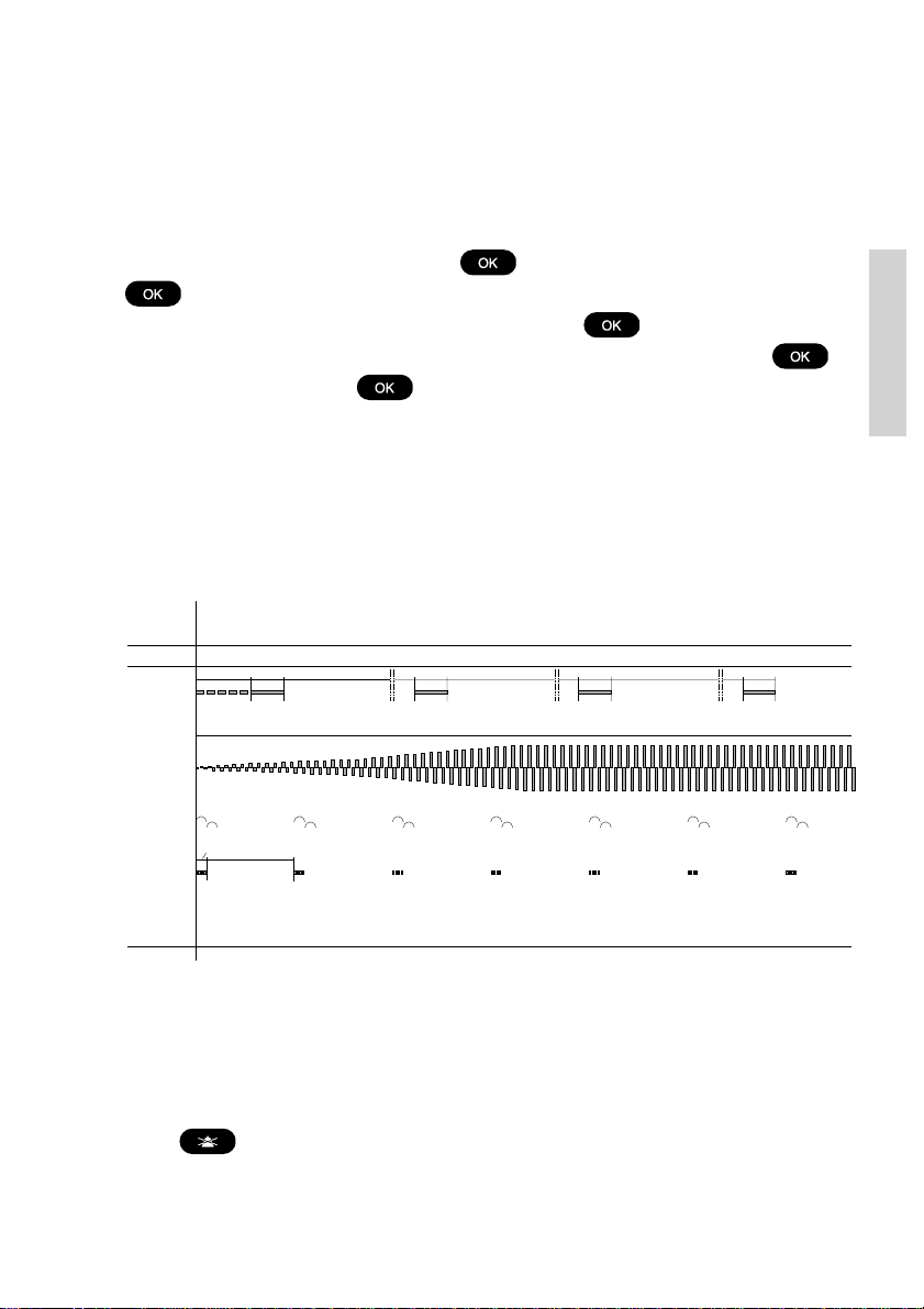
tones
The VHF rings in various ways according to the nature of the call, as shown in the following
diagram:
TONE SIGNAL
3 sec.
DISTRESS
TRANSMIT
DISTRESS
URGENCY
5 sec.
&
3 1/2 - 4 1/2 min
Tx Tx Tx Tx
3 sec.
3 1/2 - 4 1/2 min
60 sec.
3 sec.
3 1/2 - 4 1/2 min
3 sec.
Detail
SAFETY
CALLS
ROUTINE &
PSTN
39717
If an individual call acknowledgement is received, a call tone is activated that is equal to the
1 sec.
8 sec.
call tone used for receiving a call request of the same type.
Calls that are received as distress calls or calls with category distress or urgency will always
adopt the prescribed alarm sound. For any other DSC calls the call sound on reception can
be enabled/disabled from a Setup menu (4.3.2).
If a call is received initiating an alarm sound, the alarm sound may be muted by pressing the
button
in order to be able to finish current radiotelephony call. This procedure will not
affect the actual call accept procedure.
0605
15
Page 22

4.4 Working channel
A working channel will always be suggested by the system if a ship station or group is called
for a routine call. The working channel is suggested by using the following procedure:
1. Select a random channel from the list of simplex channels
2. Scan channel for traffic (open squelch)
3. If the channel is free suggest the channel.
4. If the channel is busy restart from 1.
If no channels are found to be free within 1 second no channel is suggested.
4.5 Contact list
The contact list or phone book can contain up to 200 entries.
Detail
Each entry might contain:
• Station-, group-, coast station- or public name
• Station MMSI, group MMSI, coast MMSI and/or public phone number
The contact list can be reached from the
Contacts menu (2).
Contacts
1 Call Contact
2 Show Contact
3 Add Contact
4 Edit Contact
5 Delete Contact
2
4.5.1 Calling a contact
It is possible to initiate the following calls from the Call Contact menu item (2.1):
• Individual station (ships or coast) routine radiotelephony calls
• Group routine calls
• Direct dial phone calls to a PSTN phone
Entering the Call Contact menu item will bring up a list of possible names to select. The
name list is sorted alphabetically. The alphanumeric keypad can be used for quick search on
the first letter in the contact name (using wheel mode). Selecting a contact will show data for
the contact in question. Example:
Call Contact
Name:
Peters Oil
MMSI: 003456789
PSTN no: 0045 68098765
When is pressed the appropriate call generator
will be initialized, based on the data.
If a PSTN number exists for the selected contact the PSTN call flow is initiated. Therefore it
is important the corresponding MMSI number for that contact being a coast station number.
If only an MMSI number is present for the contact, a ship station, group or coast station call
is initiated:
16
0544
Page 23
• If the MMSI number is a group number, the group call flow is entered from the
Add Contact
Name:
MMSI:
PSTN:
Save contact
Add Contact
Name:
Anders Fisker
Add Contact
Name: Anders Fisker
PSTN:
Save contact
MMSI:
window where a channel is selected.
• If a ship station number MMSI is available, the station call flow is entered from the
window where a channel is selected.
• If the MMSI number is a coast station, the operator will be led to the transmit
verification window for a station call.
4.5.1.1 Using the Contact list from the Call Sequences
Any call initiated from the DSC call menu that needs an MMSI number or PSTN number,
might search and use that number from the Contact list. If “Search for Contact” is selected
from anywhere in a call flow the contact search list is entered. Selecting the contact with
will return to the corresponding MMSI/PSTN entry window in the call flow with the
selected number information pre-filled.
4.5.2 Show contact
Via the menu item 2.2. it is possible to search for a contact’s information without changing or
initiate anything.
4.5.3 Adding a new contact
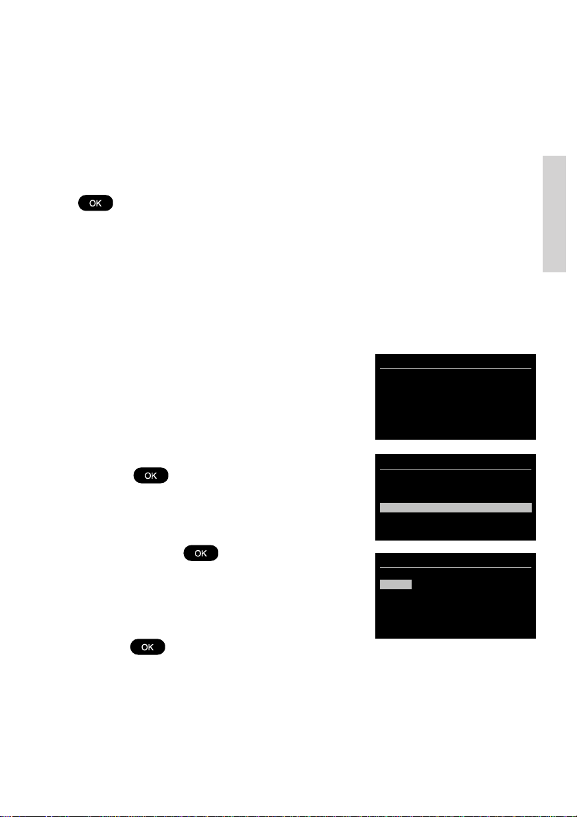
If you want to add a new contact to your list, go into menu item 2.3. The following empty
contact window will appear:
Detail
The focus bar is used to control what field the operator
wants to put information into.
Example if
After having pressed the contact information
looks as follows:
Proceed with the necessary data entries.
When finished move the focus bar to “Save contact”
and press
As a minimum a contact name and a valid MMSI number
must be entered. If a PSTN number is entered the MMSI
number for that contact must be a valid coast station
MMSI number (00*).
See also Section 4.1.2
0605
is pressed:
.
17
Page 24

4.5.4 Editing the contact list
Any contacts from the list can be edited using a similar principle as described above using
menu item 2.4.
4.5.5 Deleting a Contact Entry
Any contact can be deleted from the contact list. If menu 2.5 is selected the contact can be
searched for in the list. When found and selected with
from the contact list.
the contact will be removed
4.6 Settings for DSC
The following sections describe the settings that can be applied to different call types.
Detail
4.6.1 Special calls
The VHF is capable of supporting transmission of All Ships DSC urgency messages with
second tele-commands:
• Medical transports
• Ships and Aircrafts
These settings can be changed only from the service interface. Reception of these calls is
always possible.
If the VHF is configured for using these calls it will work in the following way:
• After powering up (normally) the VHF it will not be possible to use these call types
(message: “Call type not enabled in VHF” if selected.)
• Each of the call types can be enabled via the menu 4.5.3. (the filled square indicates
the call type that is enabled).
• After enabling the call property can be added in an All Ships Urgency call sequence.
4.6.2 Automatic ackno wledgement
The VHF can be set to automatic acknowledgement of the following calls:
• Safety position requests - Default disabled after power-up
• Safety test requests - Default enabled after power-up
• Routine polling requests - Default enabled after power-up
After power-up the behavior can be changed from menu 4.5.4.
The automatic acknowledgement (if enabled) will take place without informing the operator.
The calls are stored in the receive/transmit log. The operator might experience a short
interruption in functionality while the automatic acknowledgement takes place (e.g. scanning,
dual watch).
18
0544
Page 25

4.6.3 Automatic channel shift
The VHF can be set to automatically changing the working channel on receipt of the
following call types:
• Individual radiotelephony acknowledgement with a valid channel information
• Radiotelephony group calls with valid channel information
• Radiotelephony all ship safety calls with valid channel information
The set-up is done via menu 4.5.5. The setting will survive powering off the product.
If enabled, a received call will start the (normally) periodic alarm only once. The channel will
switch immediately after and the window is closed.
The automatic channel shift is overruled (turned to manual acknowledgement - requiring
press on OK or a hook-on to hook-off transition) if:
• Any handset is hooked off
• The received call cannot currently be presented on the information display (due to
priority)
Distress calls and all ship calls with category distress or urgency will alert continuously until
manually handled from the front panel.
4.7 Implicit behaviour for operations with DSC
This section describes assumptions and decisions made that are critical for correct functionality, but might be hidden to the operator in the display.
4.7.1 DSC transmission
All DSC calls are transmitted on channel 70 with a transmitter power of 25W. Distress,
urgency and non-test safety calls are always transmitted. Other calls are sent only if the
radio is not already recognizing a DSC message on channel 70.
Detail
4.7.2 Transmitting undesignated distress
Undesignated distress (solely created using the DISTRESS button) does not show any
message prior to the actual transmission. The following message will be sent:
Format specifier: Distress (112)
Self-Id: <Your MMSI number>
Nature of distress: Undesignated (107)
Distress coordinates: Automatically inserted if position is available (e.g. from GPS),
otherwise unknown (9999999999)
Time of position: Automatically inserted if time of position is available (e.g. from GPS),
otherwise unknown (8888)
Subsequent communication: 100
EOS: 127
0544
19
Page 26

4.7.3 Verification of a DSC call before transmission
The final step in each DSC call sequence is the verification window, in which it is possible to
verify the call that is about to be transmitted. By default only information that may be
influenced in the call setup will be displayed. Example:
What is not indicated to the user is the fact that calls are
formed
according to the specifications ITU R.493-11.
For example in a call (an individual station call request)
the following information is not shown to the user:
st
•1
tele-command: F3E/G3E Simplex TP
• EOS: Acknowledgement request (RQ = 117)
For all radiotelephony calls transmitted to all ships or to a group of ships:
Detail
• EOS: End Of Call (127)
Transmitted acknowledgement calls are not shown in any verification window before
transmission. The acknowledgement of any received individual call request will be according
to ITU R.493-11. The manipulation of the received call will be:
• Self-ID in the received call is used as address in the transmitted call
• Address in the received call is used as self-ID in the transmitted call
• EOS: Acknowledgement (BQ = 122)
st
•1
tele-command might be changed to “Unable to Comply” (104) on operator’s
request, stating the selected reason.
For all received or transmitted calls the full information can be retrieved from the DSC log.
Transmit Station Call
MMSI: 001234567
OK/send
<Menu/back
4.7.4 Receiving DSC calls with errors
Distress calls are regarded of such importance that even if they are received with errors they
will, as far as possible, be received and displayed on the screen. If a call is received with
errors this will be indicated with a “receive error” (REC ERR) marking next to the heading of
the call. In this case the full integrity of the data is not to be trusted, and the handling
possibilities (e.g. relaying the call with direct use of the received data) are limited by the
equipment.
4.7.5 Priority of DSC versus VHF
If a situation occurs where there is a conflict between the VHF and the DSC functionality (for
instance voice transmission on a working channel – using PTT, simultaneously with transmission of a DSC call), the DSC transmission will be prioritized. As a consequence the
following VHF functions may need to be re-initiated if the DSC activity has occurred while
these were active:
• Replay
• Scanning
• Dual watch
• PTT
A normal received DSC call request will appear on the screen as soon it is recognized on
channel 70. This will not affect VHF radiotelephony before OK is pressed, unless automatic
channel shift has been configured (See chapter: Automatic channel shift:)
20
0605
Page 27

4.8 Radio configuration and settings
This section describes the configuration and settings possible to control from the operator
front panel and is not described elsewhere in this manual.
If configuration of the VHF beyond these possibilities is required, contact the local T & T
representative for assistence.
4.8.1 Idle display
Whenever the radio is left in a state where the information/message display is not in use
(pure radio communication mode), the information display will return to idle or stand-by
mode. This will also be the case if the unit has no active messages on the display, or is left in
a menu, un-operated for 10 minutes.
The required and preferred default idle display is the one where position and time stored for
DSC operation are shown along with the ship’s identity (9-digit MMSI). This mode will always
appear after start-up. The user might change the default display to be blank (zero illumination
to minimize disturbance at night). To use this mode menu (4.6.2) select Idle Display .
Pressing OK will toggle the blank display to be used.
If the blank display is selected for idle display, and the radio goes into activity mode, the idle
mode will just leave the screen blank. To display the position and identity information quickly
in this mode briefly activate press the on/off button. This will result in the information screen
being displayed for 15 seconds after which it goes blank again.
4.8.2 Notations for date and time
On the idle display and when the UTC radio time needs to be manually updated the notation
for time entry is:
• yyyy/mm/dd hh:mm
Detail
In all logs (DSC logs and system logs)
• dd/mm hh:mm (in overview list)
• dd/mm-yy hh:mm:ss (in detail log descriptions)
The above notations are in force regardless of conventions that might traditionally be used in
languages other than English.
4.8.3 Language
The RT5022/RT5020 provides a selection of pre-programmed language packages. This
feature enables the presentation of the text/information display section in a language
different from the default language (English) by selecting the appropriate language in the
Language
supported. Other language selections may become available at a later stage, in which case
such will be launched with future software updates.
As the RT5022/RT5020 approvals are based on the default language (English), the following
convention for operation has been defined:
0611
menu (4.6.4). Only the language selections available in this menu point are
21
Page 28
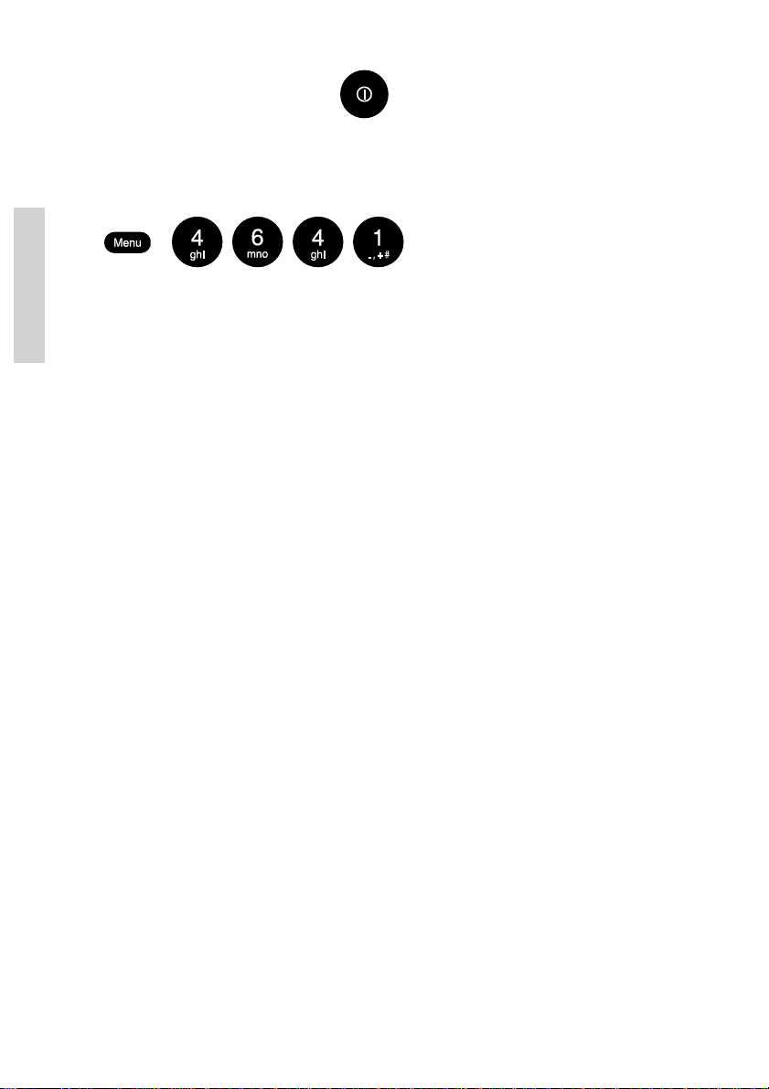
• When turning off the VHF using the button, the VHF - for regulatory reasonswill power up in the default language (English) mode when again turned on,
irrespective of which language selection had been made prior to turning off the VHF.
• The following sequence of key strokes will select the default language (except when
the VHF is in distress state – waiting for a distress acknowledgement):
Internationally recognized abbreviations such as the geographical directions (N, S, E, W),
Detail
DSC symbol notations (Ack. RQ, Ack. BQ and EOS) etc. are maintained in all the language
packages.
4.8.4 Privacy talk mode
It is possible to configure the radio to be used for a certain level of privacy. Privacy mode is
only applicable if the system is installed with CU5000 remote CU unit(s).
In privacy mode all received voice (speaker and earpiece) will be muted to the CU5000
remote units when the transceiver handset is lifted (“OC” is displayed in CU5000 display).
An incoming alarm sound will overrule privacy mode.
Privacy mode is enabled/disabled via menu 4.3.3.
4.9 Voice scrambler
For the RT5022/RT5020 products a voice scrambling option is available. The voice scrambling option is enabled by entering of a pin-code (key) into the VHF transceiver. This pin
code is uniquely matched to the serial number of the VHF, i.e. one specific pin code will
enable the scrambling option in one specific VHF only.
Once in possession of the required pin code the scrambling option is enabled from the menu
point
Scrambling Pin Code
entered from the transceiver keypad.
When the pin code has been entered and the scrambling option enabled, the scrambling
feature remains permanently available for selection.
in the System Setup menu (4.6.5). The 10-digit pin code is
For details on how to obtain the scrambling feature for your SAILOR RT5022/RT5020 VHF,
contact your local Thrane & Thrane representative.
4.9.1 Using the voice scrambler
Voice scrambling is an application that allows for two stations to set up a scrambled voice
conversation on a working channel. This means a conversation that prevents any other
station from listening to that conversation.
The synchronization key between the two parties is simply calculated from the opponents
MMSI number. This means no public key is necessary. The scrambled call can be set up
immediately between two RT5022/RT5020, if both are having the scrambler application
enabled (scramble pin code is set).No public key is necessary.
22
0611
Page 29
The scrambled call can be set up immediately between two RT5022/RT5020, if both are
having the scrambler application enabled (scramble pin code is set).
The voice scrambler can be initiated by any of the two parties from the main menu (6).
Selecting the scrambler will initiate a sequence similar to a DSC station call. The 9-digit
MMSI number of the receiver station is entered, as well as the working channel. The current
working channel is proposed in the flow (only simplex channels are allowed). A station call
request is now sent to the receiver on the DSC channel.
The call request is received on the RT5022/RT5020 as a normal DSC station call request,
but when the call is acknowledged the scrambler key is automatically negotiated between the
two stations, and conversation is scrambled (scrambling state is clearly visible on the
screen).
The scrambling-mode is abandoned in the following situations:
• Hook-on (see also 7.1.15)
• Press
• Press
• Press
• Receiving Distress or an Urgency call types
Please note that some country authorities may request clear voice identification of the two
parties before scrambling is initiated.
Scrambling on channel 16 is prohibited. Scrambling on certain other channels might be
blocked (country specific).
During scrambling the replay function is deliberately disabled.
4.10 Automatic conditions
The following automatic conditions are activated immediately after power-on:
• If the VHF is starting up with no error messages in the display, or any warning/
error sounds, all functionality is available for the equipment as described in this
manual – all software is running OK.
• The radios transmitter and transceiver circuits are constantly monitored for stable
frequency, and transmitter output power. Failures detected on these parameters will
be displayed on the VHF information display during normal operation. No special
tests need to be carried out.
Detail
0611
23
Page 30

4.11 Software releases
4.11.1 Radio software release
The RT5022/RT5020 running software version can be read out from menu 4.6.1.1. The
version information displayed is partitioned into three sections:
• Main Release X.YY.zz. Bundled sample software release tag. Will follow host
processor software tag.
• Version X.YY.zz (DSP). Sub-version for the audio DSP image.
• Version X.YY.zz (BM). Boot monitor version.
The indices are explained as the following:
Detail
• Index X is increased if major product updates are required - e.g. introduction of a
new radio model. Requires certificate update if increased.
• Index YY is increased if major feature update or serious bugs are implemented.
Requires certificate update if increased.
• Index zz. This index is increased if small software changes are made during product
life-time. For a new version the index will start as X.YY.00; small changes will add up
ie.e X.YY.01, X.YY.02 etc. For software releases with only the zz index increased,
Notified Body will be “informed” only, without the need for updating the certificate until
next X.YY.00 release is at stake. If zz equals 00 it might be omitted in the display.
4.11.2 Remote control unit software release
The CU5000 accessory units software can be read out the following way:
1. Turn off the CU.
2. Hold down [DIM] and [CH^] while turning the CU on (pressing [ON]).
3. The SW version (Xy) is shown in the display (as long as [ON] is
pressed).
The version is partitioned in two sections:
• Digit X. Major release update. Certificate update required if increased.
• Digit y. This digit is increased if small software changes are made during product lifetime. For a new version the index will start as X0; small changes will add up ie.e X1,
X2 etc. For software releases with only the y index increased, Notified Body will be
“informed” only, without the need for updating the certificate until next X0 release is
at stake.
24
0605
Page 31
5 Errors and warnings
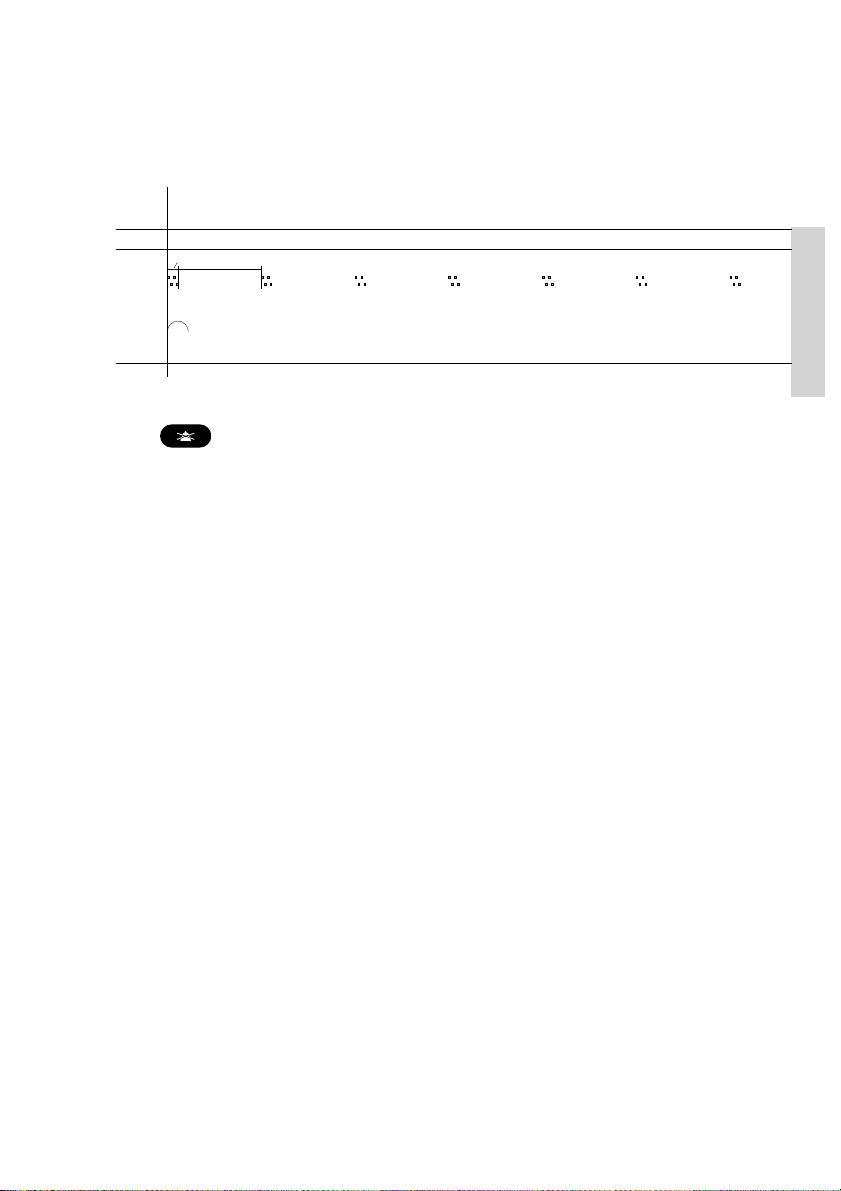
Errors and warnings are shown in the display accompanied by the sounds shown in the
figure below:
TONE SIGNAL
1 sec.
ERRORS
WARNING
& INFO
39718
In case of an error or warning message it is always possible to mute the alarm sound.
Press
the actual read-out and accept procedure for errors and warnings.
Error and warning messages are shown in the information display. Examples of a warning
can be a reminder to enter position manually each 4 hours, or that the GPS signal suddenly
is missing.
5.1 System event logging
Errors received as pop-up and information windows shall be logged in the event logging
system for later read out. The error logs are accessed from menu (4.6.3.1).
From menu 4.6.3.2 at least the following statistics are available:
• On time (<xxxx>d <yy>h <zz>m)
• Number of power failures
• Number of missing GPS situations
• Number of Tx activations
• Number of transmitted DSC calls
The information is read only on the front panel. Counters can be reset only from the service
interface
8 sec.
in order to finish the current radiotelephony call. This procedure will not affect
Detail
5.2 Troubleshooting
If you doubt that your VHF system works properly, it is of great importance that you find the
reason and assure that the equipment is properly serviced if any of the devices are failing.
You should contact your authorized dealer for tecnical support of your equipment. But, before
you do that you can go through a list of actions to fix the problem by yourself and save time.
0605
25
Page 32
5.2.1.1 Ship´s power
Ship´s power may occasionally be interrupted for a short time, e.g. if switching between land
power or generator power. The VHF equipment will turn off immediately when power is
failing. If power does not resume within 10 minutes the VHF cannot be expected to start up
automatically.
5.2.1.2 Fuses
If a press on the ON/OFF button does not turn on the VHF, though ship´s power is present,
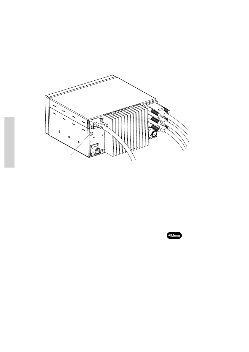
check if the fuse may have blown. The main fuse is located on the rear side of the VHF, just
below the power plug. Replace fuse with a new one, if found blown.
System
Fuse 15A ATO
5.2.2 Self-test
Symptom: Radio operation is difficult.
It is possible to make a self-test of the equipment user interface. Any entry means and
readouts can be verified in the self test. The test is executed from menu 5.
If any of the following tests are failing the local Thrane & Thrane representative should be
contacted for assistance.
5.2.2.1 Key test
All push buttons can be checked using the self-test in menu 5.1. Pressing or releasing any
key on the front panel will be echoed in the graphic display. Only exception is DISTRESS
and ON/OFF - which will maintain their functionality. These buttons may be pressed
periodically for a short time to check that they are functional. Pressing
the test.
5.2.2.2 Display test
The information/message display is an LCD screen. A test of all pixels in the screen is
executed in menu 5.2. Triangles are shown in the display.
5.2.2.3 LED test
The LED test will check all light indicators including the channel display. Running the LED
test (5.3) will turn on all indicators for 2 seconds, where after these will return to their
previous state.
5.2.2.4 Alarm and Audio Test
Entering this test item (5.4) will route the distress and urgency alarm sound to all speakers
where this alarm is to be heard.
Additionally the 4 external relay outputs (CALL, ALARM, AUX1 and AUX2) will be activated
for the duration of the test signal. The relays resume to their respective functional state when
the alarm tone terminates (after 3 seconds).
twice will exit
26
0611
Page 33

5.2.3 GPS
Symptom: Position requested
Possible cause/remedy: In case of the VHF, despite being connected to a GPS/position
source, prompts for entering of the position and time information the automated update has
most likely been lost either due to missing data on the line, broken cabling or the GPS/
position source has failed. Refer to the installation section in the back of this manual for
installation and connection details.
Until the automatic position update from GPS/position source is restored position and time
must be entered manually when prompted by a (four hour) timer in VHF.
In the accessory self test menu (5.6.2) the presence of postion data may be verified. If data
is present the status read out will be “connected” whereas if no data is present status read
out will be “disconnected”.
5.2.4 Accessory connection
Symptom: Some or all of the remote units do not work
Possible cause/remedy:
First turn off the VHF and then turn back on. Turn on any remote units connected to the VHF,
if possible.
Check status of the remote units from the accessories menu (5.6.x). If status read out is “not
found” for a particular device communication between this and the VHF is missing.
The communication between the VHF and the remote units is by the serial Sparc II connection at the rear of the VHF. Remote unit(s) may be connected directly to this Sparc II
connector or via the Connection Box and/or Extension Box (refer to installation section in the
back of this manual).
In case of an Alarm Panel (AP4365) being connected to the VHF check and verify that the
red “VHF DISTRSS” button in the Alarm Panel is lighted. If this is not the case check and
verify that power is available to the Alarm Panel in order for this and its serial bus to be
operational.
Detail
Any communication problems on the data bus will not otherwise affect the VHF functionality.
5.2.5 DSC routine testing
On a regular basis the DSC installation should be checked.
Verification of the complete DSC installation, with antennas, should be done by transmission
of a Safety Test call to another station (coast or ship). The test call is generated using the
DSC call flow via menu 1.4.3.2.3.
The call should normally be replied by the receiving station without questioning. The default
configuration of an RT5022 is auto-acknowledgement of any received Safety test call
requests. If a ship is equipped with multiple radios a second radio can be the station to check
up against. The transmitting RT5022/RT5020 will not receive its own transmitted calls.
If there is only a single radio on a vessel, a facility is built into the unit where the DSC engine
can be verified using a test call that is internally looped without activating the radio transmitter PA. The test is executed via menu 5.5. The call sequence that is verified, is an Individual
Safety Test Call directed to own MMSI. The test status is read in the display.
0605
27
Page 34

5.2.6 Missing MMSI
Symptom: DSC operation is not working
Possible cause/remedy: When powering up the VHF for the first time after leaving factory
no MMSI identity resides in the VHF. For the DSC operation to function the VHF must be
programmed with MMSI identity (refer to menu 4.5.1).
5.2.7 Radio time
Symptom: DSC logs are sorted with wrong time stamp or radio time is incorrect
Possible cause/remedy: A wrong radio time indication should occur only if GPS position
source is not connected or providing correct time data. A valid GPS time signal will update
the UTC time used for time stamping the DSC logs.
If a GPS/position source is not connected to the VHF and hence position and time is entered
manually, it is necessary that the “radio time” also be entered manually, at least on powering
up of the VHF. This will ensure correct time stamping of the DSC logs.
The UTC time is the suggested time to be entered when prompted for entering position and
time manually (every four hours).
5.2.8 Channel not free
5.2.8.1 DSC Channel not free
Symptom: DSC transmission delayed
System
Possible cause/remedy: Transmission of a DSC call which is not of category distress or
urgency will be postponed if the VHF is already in the process of decoding an incoming DSC
call. As soon as this decoding process has finalized the transmission will take place.
5.2.8.2 Working channel not included in DSC call
Symptom: In a DSC station call a proposed working channel is included resulting from
scanning through a preset table of working channels. If, for some reason a free channel from
this table is not found withing 1 second, no proposed working channel will be included in the
DSC call.
Possible cause/remedy: If the squelch is at all times open the channels thus scanned
through will all be interpreted as occupied. Adjust for higher squelch setting to avoid this
situation.
5.2.9 Device failure
If any of the checks and tests described in this section do not assist in resolving any
difficulties experienced in the operation and/or performance of the VHF installation, a fault
may have developped in the VHF itself.
In seeking further assistance from an authorized Thrane & Thrane representative be sure to
provide as much information as possible in regards to the observed behaviour also including
the type of the VHF, its serialnumber (printed on type label or found in menu 4.6.1.2) and
software Main release version (menu 4.6.1.1).
28
0611
Page 35
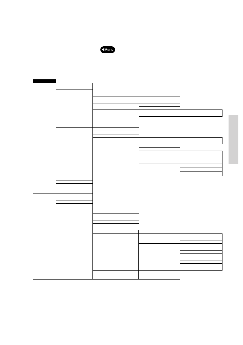
6 Menu tree
p
p
p
y
p
y
y
A
p
g
g
g
g
T
A
t
As S
A
t
A
g
play
g
4.3.2.1.1
Low
4.3.2.1.3
High
w
4.3.2.2.3
Medi
y
4.3.2.3.1
M
4.3.2.3.2
Low
4.3.2.3.4
High
This section lists the full menu tree of the VHF.
The table describes the un-regretted forward flow that is initiated after selection of certain
menu items. Generally, pushing
previous window.
MENU
DSC Call
1
Conta cts
2
Sca nni ng
3
Settin
4
1.1 Statio n Call
1.2 PSTN Call
Call
1.3 Grou
1.4 Eme rgency
DSC Logs1.5
2.1 Call Co ntact
2.2 Show Contact
2.3 Add C ontact
2.4 Edit Con tact
2.5 Dele te Co ntact
3.1 Scan All Chann els
3.2 Scan Tab le A
3.3 Scan Tab le B
3.4 Scan Tab le C
3.5 Edit Scan Tables 3.5.1 Scan Tab le A
s
Pos ition & T ime4.1
Contras t
4.2 Dis
Audio4.3
1.4.1 Com
1.4.2 Com pose Urgency 1.4.2.1 All Ships
1.4.3 Com
1.4.4 Com
1.4.5 Com
1.5.1 DSC Distr es s Lo
1.5.2 DSC Rece ive Lo
1.5.3 DSC Tr ansm it L o
1.5.4 Print in
3.5.2 Scan Table B
3.5.3 Scan Table C
4.1.1 Set Pos ition & T ime
4.1.2 Set Radio T ime
4.1.3 Show Pos ition
4.3.1 Hands et Volum e
4.3.2 DSC Alar m Tones
4.3.3 Privacy Mode
in the menu tree or flow sequence will return to the
ose Distress
ose Safet
ose Rela
ose Distress Ack
1.4.2.2 Individual
1.4.3.1 All Ships
1.4.3.2 Individual
1.4.4.1 Distre ss Rela
Distress Relay Ack
1.4.4.2
1.5.4.1 Print Distre ss Log 1.5.4.1.1
1.5.4.2 Prin t Re ceive Lo g
1.5.4.3 Prin t Transm it Log
1.5.4.4 All Inco ming DSC
1.5.4.5 All Outg oing DSC
4.3.2.1 Warnin
4.3.2.2 Routine Call
4.3.2.3 Safet
Call
Ena ble Pri va cy
Disable Privac y
1.4.4.1.1
1.4.4.1.2
1.5.4.1.2
4.3.2.1.2 Medium
4.3.2.2.1 Mute
4.3.2.2.2 Lo
4.3.2.2.4 High
4.3.2.3.3 Medium
ll Ships
Individual
ransmitted Distress
Recei ved Distress
s Tex
ymb ols
Disabl e
s Tex
s Symbols
Disabl e
um
ute
System
0605
29
Page 36
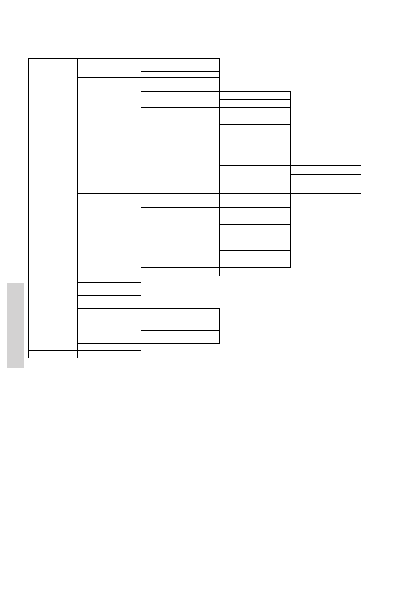
Medical T
Shi
Saf
G
Settings
4
Sel f Test
55.1Key Test
Voi ce Scra mble r
6
Channels
Channels4.4
4.5 DSC 4.5.1 MM SI Num ber
4.6 System 4.6.1 Device Identification 4.6.1.1
5.2 Display Te st
5.3 LED Tes t
5.4 Alarm Test
5.5 DSC
5.6 Accessories 5.6.1
5.7 Print Test Page
4.4.1 Channe l Mod e
4.4.2 Channe l Info
4.4.3 ATIS Call sign
4.5.2 Group MM SI
4.5.3 Special Calls
4.5.4 Auto Acknow ledgeme nt
4.5.5 Auto Chan nel Sw itch
4.5.6 MMSI Sub-address
4.6.2 Idle Display
4.6.3 System Log
Language
4.6.4
4.6.5 Scramb le Pin Cod e
Alarm Panel
GPS
5.6.2
LAN Interfac e
5.6.3
Pr in t e r
5.6.4
Optional Handsets
5.6.5
ranspor ts
ps and Aircrafts
Saf ety Test
Routine Polling
ety Position
RT acknowledgement
roup Calls
All Sh ips Saf ety Calls
Value of X10 digit
4.5.6.1
X10=0 mode Ac knowledge Non-zero
4.5.6.2
4.6.1.2
4.6.3.1
4.6.3.2
SW Ver sion
Serial Number
Blank Display
Errors
Statis tics
English
Dan sk
Ita lia no
Deu ts ch
Acknowledge Zero
Reject Call
30
0605
Page 37
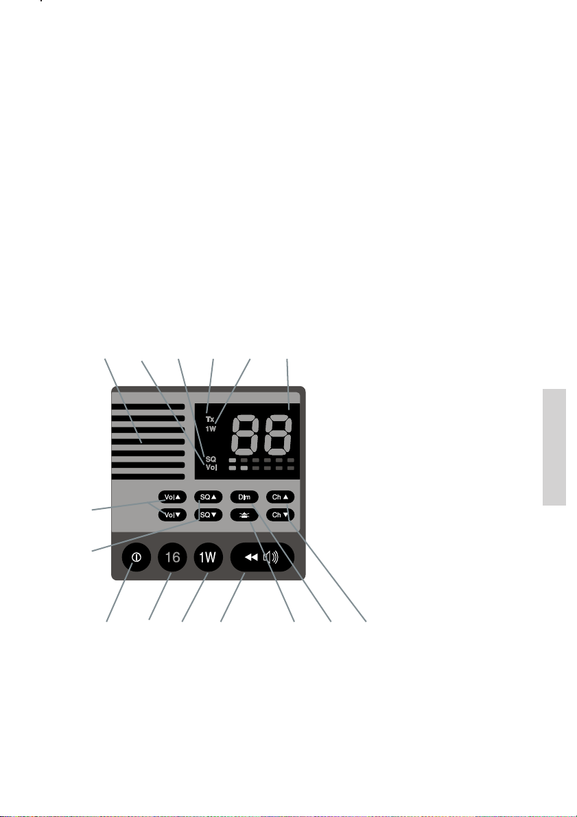
7 Optional functional devices
The maximum system configuration possible with your VHF installation with VHF is shown
in the first part of the installation section.
The present chapter will describe the functionality and behaviour of the following optional
functional devices:
7.1 Semi-functional control unit
The semi-functional control unit CU5000 is an optional unit connecting an additional remote
handset to the VHF. Installation of control units should be performed only by an authorized
service person.
7.1.1 Controls and indicators
1 2 3 4 5 6
7
8
• 1 or 2 remote handset control units
• One alarm panel
• Printer + LAN interface + printer server
1. Loudspeaker
2. Squelsh level indicator
3. Volume level indicator
4. Tx
5. 1W
6. Display
7 Volume up/down
8. Squelch up/down
9. ON/OFF
10. Quick-select key for channel 16.
11. 1 W
12. Replay push button
13 Mute alarm
14. Dimming
15. Channel up/down
Channels
0605
9 10 11 12 13 14 15
31
Page 38
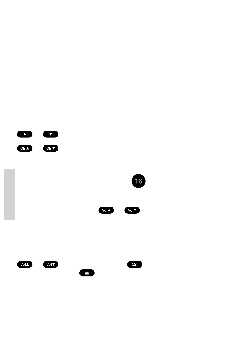
7.1.2 Operation
The optional handset is intended for VHF radiotelephony only. There will be no DSC
functionality supported except for:
• The functionality or lifting of the CU handset follows the default handset on the main
radio (see Section DSC receive), when receiving a DSC call.
• Possibility to mute DSC alarm sound – not to handle the DSC call.
7.1.3 ON/OFF
The semi-intelligent handset will always be turned off default after VHF unit is powered. The
off state is indicated by no activity or light in the CU.
The unit can be turned on and off (press for 1 second) on the ON button.
If the main unit is powered off the handset control unit is always turned off.
7.1.4 Channel selection
Channel selection is done by using exactly the method as described for VHF by using
and .
On the optional handset control unit these buttons are marked
and respectively.
Channel change requests are sent to the main VHF unit, and the main VHF unit will change
channel and update the CU display. The same channel number will be applied to all the
displays in the system.
A quick channel 16 selection is available by pressing
.
7.1.5 Volume
The volume is controlled by using the and buttons.
Channels
Pressing these buttons will affect only the internal CU speaker as well as optionally connected external CU speakers. The volume adjustment will be active only for the specific local
handset. Therefore the volume bar on the main VHF unit is not updated during adjustment.
A local volume indicator always shows the speaker volume on the CU. If the volume is
adjusted to the mute level the VOL LED will flash (1 Hz).
The earpiece volume in the handset connected to the CU is adjusted using the
and buttons while holding down the button.
This alternative usage of the
• The handset is hooked off, and
• No active alarm sound to be muted
After power-up all volume levels set during the last operation are restored as they were
before power-down.
button will be possible only when:
32
0605
Page 39
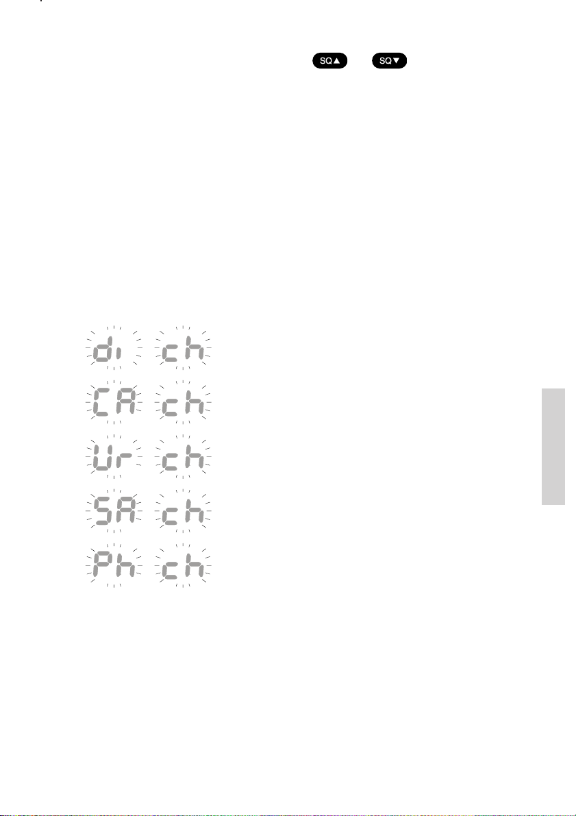
7.1.6 Squelch
The squelch level can be adjusted by using the and buttons.
Pressing the buttons will contribute to the global squelch setting on the radio. Squelch
indicators on the handset CU and on the main unit will always follow each other regardless of
the control input used for adjustment.
NOTE: If a channel is reached where the squelch setting was programmed from the main
unit, usage of the squelch control will set the level for that particular channel, and reset the
squelch programming.
7.1.7 Dimming
Dimming the control unit display and keypad backlight and 1W LED is done exactly as
described for the VHF, but with no graphical information.
7.1.8 Receiving a DSC call
If a DSC call is received the following will show on the CU channel display depending of the
call type:
all type:
alternating
...
If an active distress call was received
(changing with 1Hz).
...
If a routine call was received
...
If an urgency call is received.
...
If an safety call is received.
...
If an PSTN call is received.
Normal radiotelephony calls can be acknowledged from the semi-intelligent handset making
the HS hooked to HS un-hooked transition.
If an error or warning occurs the following is displayed:
0605
Channels
33
Page 40
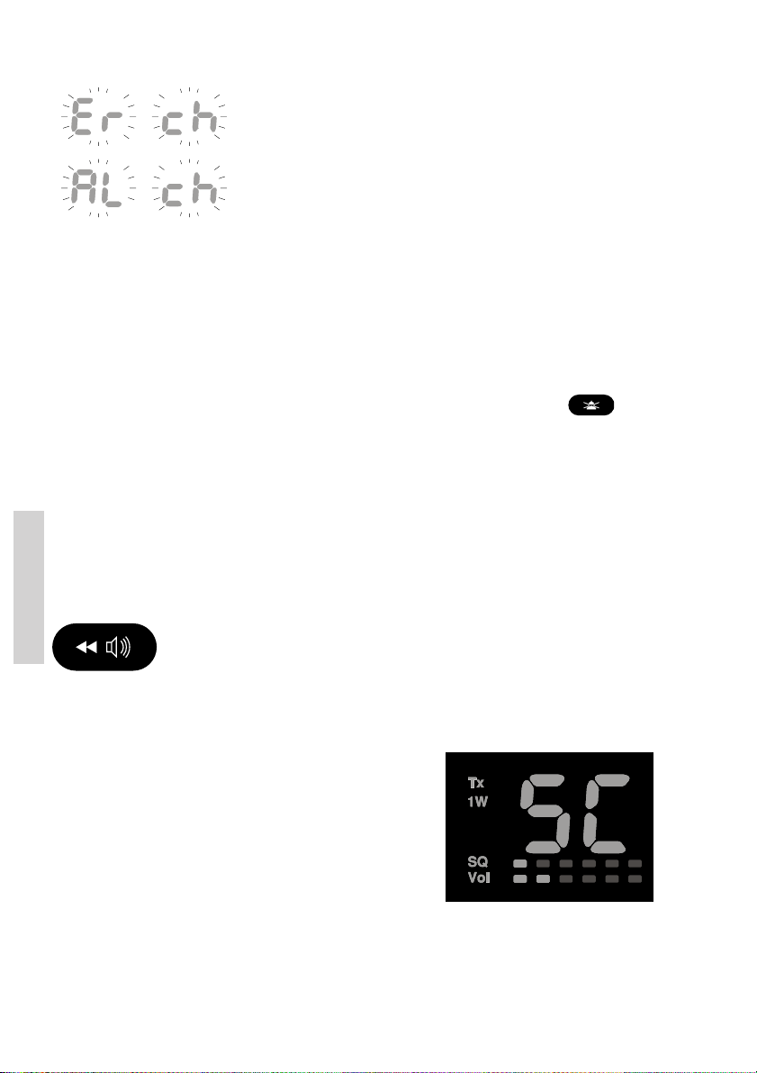
alternating
...
on errors.
...
on alerts.
This indication will remain until the DSC call has been handled from the main unit. Though
normal radiotelephony calls can be acknowledged from the semi-intelligent handset making
the HS hooked to HS un-hooked transition.
7.1.9 Muting alarms
If a DSC call is received (distress or routine) the alarm sound is heard as a mixing of the
received voice audio in the speakers and earpieces in the system. Pressing the
button will mute any alarm sound in the system, and only received voice is heard in the
speakers.
7.1.10 Transmitter po wer
Pressing the 1W button will have the same effect as described for VHF. 1W LED on CU will
follow the 1W LED on the main unit.
7.1.11 Replay
The replay facility works exactly the same way as described for the main VHF unit when the
Channels
The navigator counter (seconds back in received signal) is shown on the CU display.
button is pressed.
7.1.12 Dual watch and scanning
There are no possibilities of controlling dual watch or
scanning. During dual watch initiated from the main
VHF the working channel is displayed in the display.
During scanning the display is indicating this by “SC”.
Locking on any channel will, of course, switch the display
to that channel.
34
0605
Page 41
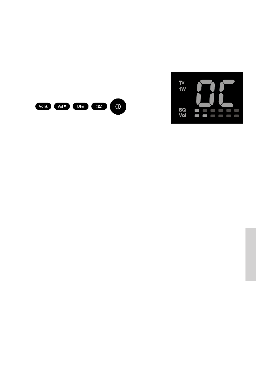
7.1.13 Multiple handsets in the system
If multiple handsets are connected in the system the following priority is given (to PTT –
microphone control) if multiple handsets are lifted:
• The default handset is always given priority if lifted.
• Any optional handset lifted first takes priority over another optional handset.
A warning “OC” is written in the display near any handset (VHF unit or CU) that has lower
priority, as soon the prioritized handset is lifted.
If an optional handset is not given priority (“OC” written
in display) it will be possible to use only the following
buttons on the CU:
7.1.14 Optional handset CU VHF operation while main unit is in
menu or text entry mode
If the main VHF unit is operated in menu or text entry mode, there will be certain buttons on
the VHF main unit that do not respond to their primary functions. Seen from a CU perspective all functionality is maintained if “OC” is not shown in the telephone display.
7.1.15 Multiple handset hooked-off
Certain states (e.g. PSTN calls and scrambled calls) can be terminated with a hook-on of the
handset. The following approach is taken for installations with CU5000:
• The terminating action is only taking place if the handset that was hooked on, was
the last active handset to be hooked on in the system.
• It does not matter if the hooked on handset was the handset that had priority in the
system.
7.2 Alarm Panel AP4365
The Alarm Panel AP4365 will, when connected to the VHF, indicate this connection by
illuminating the text “VHF” in the Alarm Panel display
7.2.1 Distress initiation
Only undesignated distress messages may be initiated from the Alarm Panel.
A distress message is initiated from the Alarm Panel by lifting the cover over the VHF
DISTRESS button and pressing this for 5 seconds. Each second lapsed is audibly indicated.
After the lapse of the 5 seconds a constant sound is heard indicating that the distress
message has been transmitted from the VHF. The distress button may be released.
The VHF is now in distress mode and the distress traffic and procedures should be continued from the VHF front panel, if possible, in the same way as described for handling distress
mode from main VHF.
The Alarm Panel audible alarm on incoming distress or urgency messages may be muted by
pressing the MUTE- button.
0611
Installation
35
Page 42

Printing
1.5.4
2 Print Receive Log
3 Print Transmit Log
4 All Incoming DSC
5 All Outgoing DSC
1 Print Distress Log
7.3 Printer
An optional printer may be installed with the VHF for printing of DSC messages and logs.
Printer installatioin and hook up to the VHF equipment should be performed by authorised
and properly trained service personnel only.
Individual messages from the DSC call logs may be
printed.
The entire content of each DSC log may be printed
(via menu 1.5.4.x)
Real time printing of incoming and outgoing DSC traffic
may be enabled via menus 1.5.4.4 and 1.5.4.5.
The status of the printer server connection may be monitored via menu 5.6.4.
Printing of a test page may be commanded from menu 5.7.
Installation
36
0605
Page 43
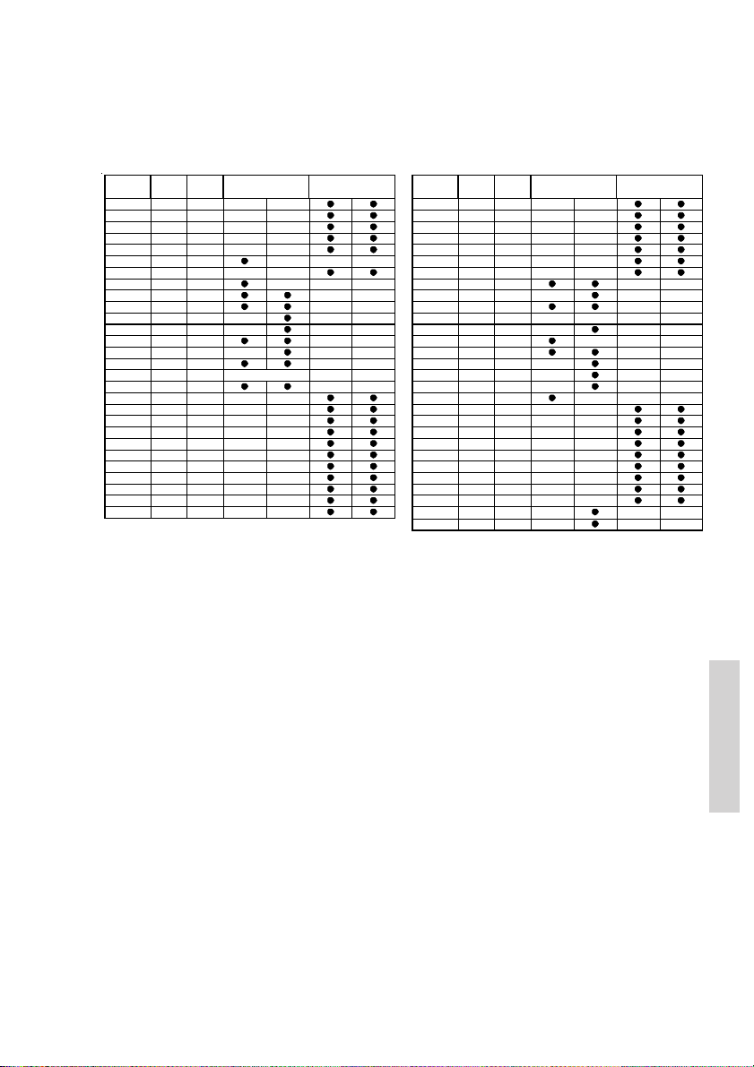
8 Maritime Channels
8.1 International channels
Channels TX RX SIMPLEX DUPLEX Channels TX RX SIMPLEX DUPLEX
MHz MHz Intership Port Port Publ ic MHz MHz Intership Port Port P ublic
1 156,050 160,650 60 1 56,025 160, 625
2 156,100 160,700 61 1 56,075 160, 675
3 156,150 160,750 62 1 56,125 160, 725
4 156,200 160,800 63 1 56,175 160, 775
5 156,250 160,850 64 1 56,225 160, 825
6 156,300 156,300 65 1 56,275 160, 875
7 156,350 160,950 66 1 56,325 160, 925
8 156,400 156,400 67 1 56,375 156, 375
9 156,450 156,450 68 1 56,425 156, 425
10 156,500 156,500 69 156,475 156, 475
11 156,550 156,550 70 156,525 156, 525
12 156,600 156,600 71 156,575 156, 575
13 156,650 156,650 72 156,625 156, 625
14 156,700 156,700 73 156,675 156, 675
15 156,750 156,750 74 156,725 156, 725
16 156,800 156,800
17 156,850 156,850 76 156,825 156, 825
18 156,900 161,500 77 156,875 156, 875
19 156,950 161,550 78 156,925 161, 525
20 157,000 161,600 79 156,975 161, 575
21 157,050 161,650 80 157,025 161, 625
22 157,100 161,700 81 157,075 161, 675
23 157,150 161,750 82 157,125 161, 725
24 157,200 161,800 83 157,175 161, 775
25 157,250 161,850 84 157,225 161, 825
26 157,300 161,900 85 157,275 161, 875
27 157,350 161,950 86 157,325 161, 925
28 157,400 162,000 87 157,375 157, 375
Di stre ss an d ca ll in g
75 1 56,775 156, 775
88 1 57,425 157, 425
Notes:
L) 1W TX power
*) Channel 87 and 88 became simplex channels following the instruction of Automatic
Identification channels AIS1 at 161.975MHz and AIS2 on 162.025MHz.
NB! The RX and TX frequencies can be read from menu (4.4.2).
DSC DS C
L)
L)
*)
*)
0605
Installation
37
Page 44

8.2 US channels
Channels TX RX SI MPLEX DUPLEX Channels TX RX SIMPLEX DUPLEX Channels WX RX
MHz MHz MHz MHz MHz
1 156,050 156,050 60
2
3 156,150 156,150
4
5 156,250 156,250 64 15 6,225 156, 225
6 156,300 156,300 65 15 6,275 156, 275 P5 W X6 162,5 00
7 156,350 156,350 66 15 6,325 156, 325 P6 W X7 162,5 25
8 156,400 156,400 67 15 6,375 156, 375
9 156,450 156,450 68 15 6,425 156, 425 P8 W X9 161,7 75
10 156,500 156,500 69 156,475 156, 475 P9 WX10 16 3,275
11 156,550 156,550 70 156,525 156, 525
12 156,600 156,600 71 156,575 156, 575
13 156,650 156,650
14 156,700 156,700 73 156,675 156, 675
15 156,750
16 156,800 156,800
17 156,850 156,850 76
18 156,900 156,900 77 156,875 156, 875
19 156,950 156,950 78 156,925 156, 925
20 157,000 157,000 79 156,975 156, 975
21 157,050 157,050
22 157,100 157,100 81 157,075 157, 075
23 157,150 157,150
24 157,200 161,800 83 157,175 157, 175
25 157,250 161,850 84 157,225 161, 825
26 157,300 161,900 85 157,275 161, 875
27 157,350 161,950 86 157,325 161, 925
28 157,400 162,000 87 157,375 157, 375
B)
!)
B)
L)
RX)
Di stre ss an d ca ll in g
!)
!)
61 15 6,075 156, 075
62
63 15 6,175 156, 175 P3 W X4 162,4 25
DSC
72 15 6,625 156, 625
74 15 6,725 156, 725
75
80 15 7,025 157, 025
82 15 7,125 157, 125
88 15 7,425 157, 425
B)
!)
B)
!)
L)
B)
B)
L)
!)
!)
!)
*)
*)
Notes:
L) 1 W TX power. Channels 13, 67 and 77 are limited to low transmission power.
B) Channels 2, 4, 60, 62, 75 and 76 cannot be selected in US mode.
!) Channels 3, 21, 23, 61, 64, 81, 82 and 83 may be legally used in some circum-
stances but not by the general public in US waters.
RX) Only RX: transmissions are blocked.
NB! The RX and TX frequencies can be read from menu (4.4.2).
*) Channels 87 and 88 became simplex channels following the introduction of Auto-
matic Identification channels AIS1 at 161.975MHz and AIS2 on 162.025MHz.
P0 WX1 162,550
P1 WX2 162,400
P2 WX3 162,475
P4 WX5 162,450
P7 WX8 161,650
Installation
38
0605
Page 45
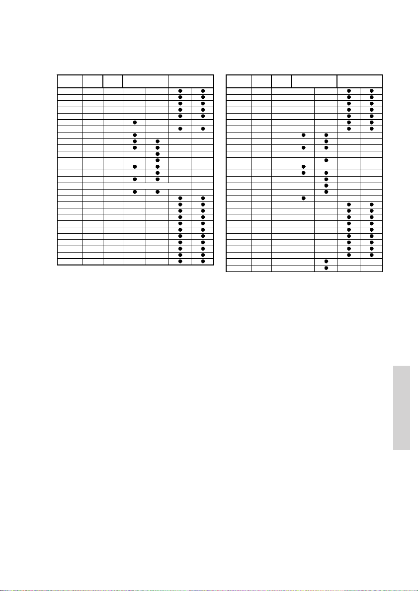
8.3 BI channels
Channels TX RX SIMPLEX DUPLEX Channels TX RX SIMPLEX DUPLEX
MHz MHz Intership Port Port Public MHz MHz Inte rship Port Port Public
1 156, 050 160,650 60 1 56,025 160, 625
2 156, 100 160,700 61 1 56,075 160, 675
3 156, 150 160,750 62 1 56,125 160, 725
4 156, 200 160,800 63 1 56,175 160, 775
5 156, 250 160,850 64 1 56,225 160, 825
6 156, 300 156,300
7 156, 350 160,950 66 1 56,325 160, 925
8 156, 400 156,400
9 156, 450 156,450 68 1 56,425 156, 425
10 156,500 156,500
11 156,550 156,550
12 156,600 156,600
13 156,650 156,650
14 156,700 156,700
15 156,750 156,750
16 156,800 156,800
17 156,850 156,850
18 156,900 161,500 77 156, 875 156,8 75
19 156,950 161,550 78 156, 925 161,5 25
20 157,000 161,600 79 156, 975 161,5 75
21 157,050 161,650 80 157, 025 161,6 25
22 157,100 161,700 81 157, 075 161,6 75
23 157,150 161,750 82 157, 125 161,7 25
24 157,200 161,800 83 157, 175 161,7 75
25 157,250 161,850 84 157, 225 161,8 25
26 157,300 161,900 85 157, 275 161,8 75
27 157,350 161,950 86 157, 325 161,9 25
28 157,400 162,000 87 157, 375 157,3 75
L)
L)
L) L)
L) L)
L) L)
Di stre ss an d ca ll in g
L) L)
L)
L)
L)
Notes:
L) 1W TX power on channels 6, 8, 10, 11, 12, 13, 14, 15, 17, 71, 72, 74 , 75, 76 and 77.
*) Channels 87 and 88 became simplex channels following the introduction of Auto-
matic Identification channels AIS1 at 161.975MHz and AIS2 on 162.025MHz.
NB! The ATIS function is enabled on all channels. RX and TX frequencies can be read
using menu (4.4.2).
Dual Watch & Scanning modes are disabled.
65 1 56,275 160, 875
67 1 56,375 156, 375
69 1 56,475 156, 475
70 1 56,525 156, 525
71 1 56,575 156, 575
72 1 56,625 156, 625
73 1 56,675 156, 675
74 1 56,725 156, 725
75 1 56,775 156, 775
76 1 56,825 156, 825
88 1 57,425 157, 425
DSC DS C
L)
L)
L)
L)
L)
L)
*)
*)
0605
Installation
39
Page 46
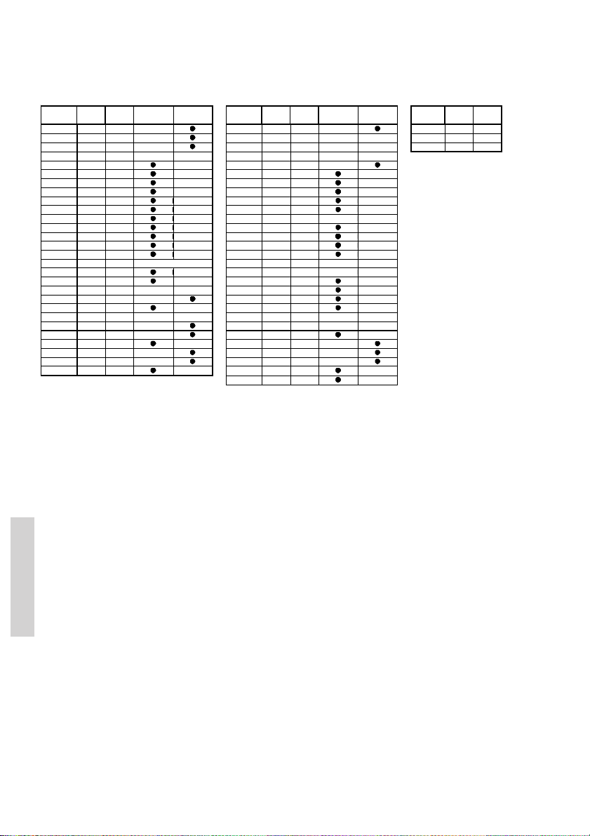
8.4 CA channels
Channels TX RX SI MPLEX DUPLEX Channels TX RX SIMPLEX DUPLEX Channels WX RX
MHz MHz MHz MHz MHz
1 156, 050 160,650 60 156,025 160 ,625 P0 WX1 162,550
2 156, 100 160,700 61
3 156, 150 160,750 62
4
5 156, 250 156,250 64 156,225 160 ,825
6 156, 300 156,300
7 156, 350 156,350 66 156,325 156 ,325
8 156, 400 156,400
9 156, 450 156,450 68 156,425 156 ,425
10 156,500 156,500 69 156,475 156, 475
11 156,550 156,550 70 156,525 156, 525
12 156,600 156,600 71 156,575 156, 575
13 156,650 156,650 72 156,625 156, 625
14 156,700 156,700 73 156,675 156, 675
15 156,750 156,750
16 156,800 156,800
17 156,850 156,850
18 156,900 156,900 77 156,875 156, 875
19
20 157,000 161,600
21 161,650
22
23 157,150 161,750 82
24 157,200 161,800 83 161,775
25 161,850
26 157,300 161,900 85 157,275 161, 875
27 157,350 161,950 86 157,325 161, 925
28 162,000
Di stre ss an d ca ll in g
RX)
RX)
RX)
B)
!)
!)
L)
L)
B)
B)
L)
63
65 15 6,275 156, 275
67 15 6,375 156, 375
74 15 6,725 156, 725
75
76
78 15 6,925 156, 925
79 15 6,975 156, 975
80 15 7,025 157, 025
81
84 15 7,225 161, 825
87 15 7,375 157, 375
88 15 7,425 157, 425
DSC
B)
B)
B)
L)
L)
!)
!)
!)
B)
B)
L)
B)
B)
RX)
*)
*)
Notes:
L) 1 W TX power. Channels 15, 17, 20, 65, 66 and 77 are limited to 1W transmission
power.
B) Channels 4, 19, 22, 61, 62, 63, 81 and 82 cannot be selected in CA mode.
!) Channels 6, 8, 23, 67, 72 and 73 may be legally used in some circumstances
but not by the general public in CA waters.
RX) Only RX: transmission is blocked.
NB! The RX and TX frequencies can be read from menu (4.4.2).
*) Channels 87 and 88 became simplex channels following the introduction of Auto-
matic Identification channels AIS1 at 161.975MHz and AIS2 on 162.025MHz.
P1 WX2 162,400
P2 WX3 162,475
Installation
40
0605
Page 47
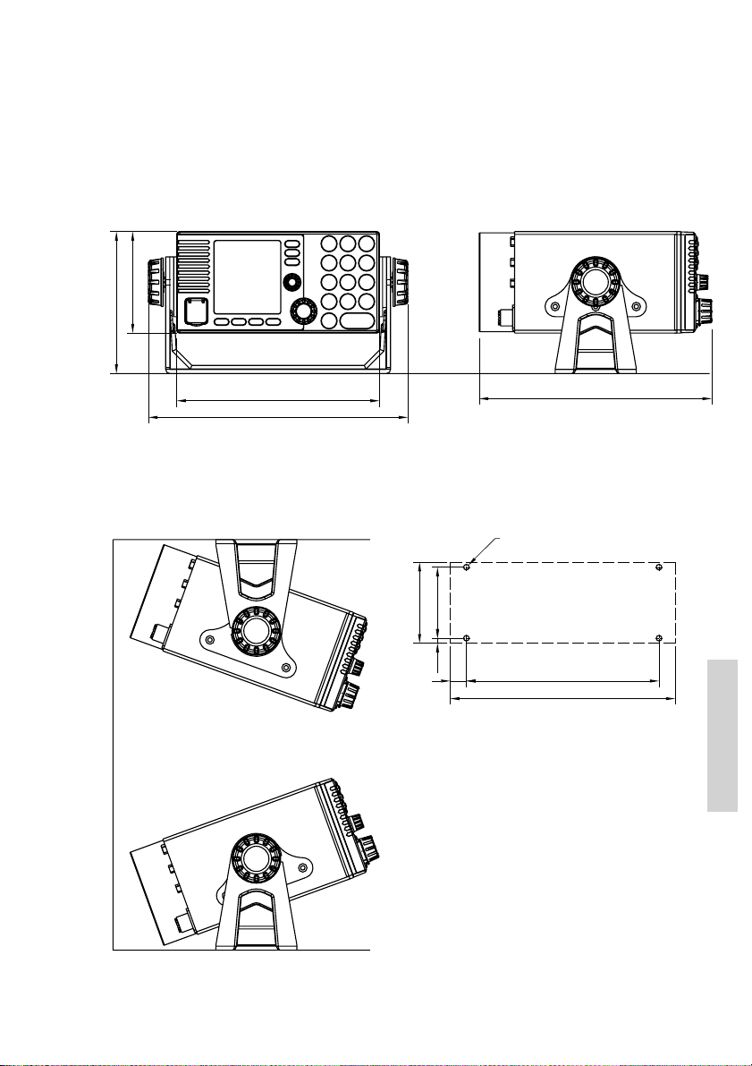
9 Installation
9.1 Mounting possibilities
VHF with mounting bracket
100
140
200
256
39835
Mounting option Drilling plan
4xø5.5
70
80
5
16
39837
Tilting +/- 20°
Weight (RT5022):
VHF 4.1 kg
Mounting bracket 1.0 kg
Weight (RT5020):
VHF 4.9 kg
Mounting bracket 1.0 kg
229
190
222
Installation
0605
39836
41
Page 48
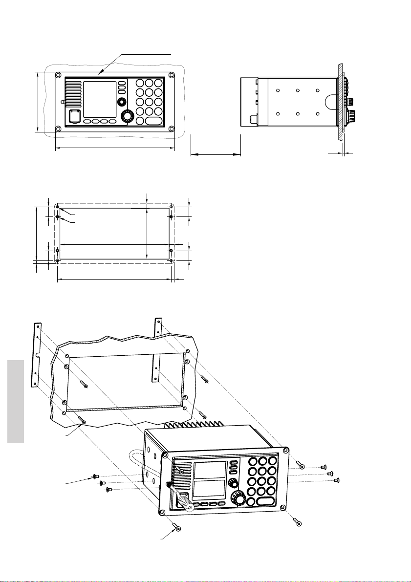
VHF with flush mounting bracket
Bracket (Option)
120
39938
Drilling plan
2020
4 pcs. ø5
4 pcs. ø3.5
108
6
39945
countersunk for M3
219
228
240
min. 100.00
Space for Cable entry
9
3
Weight:
Mounting kit
102
10
(Part no. 739814) 1 kg
WARNING:
20 20
Only use screws supplied with mounting
kit for attaching flush mounting bracket to
6
VHF radio.
4 pcs M3x30
Installation
6 pcs M4x8
39966
42
4 pcs M4x30
0605
Page 49
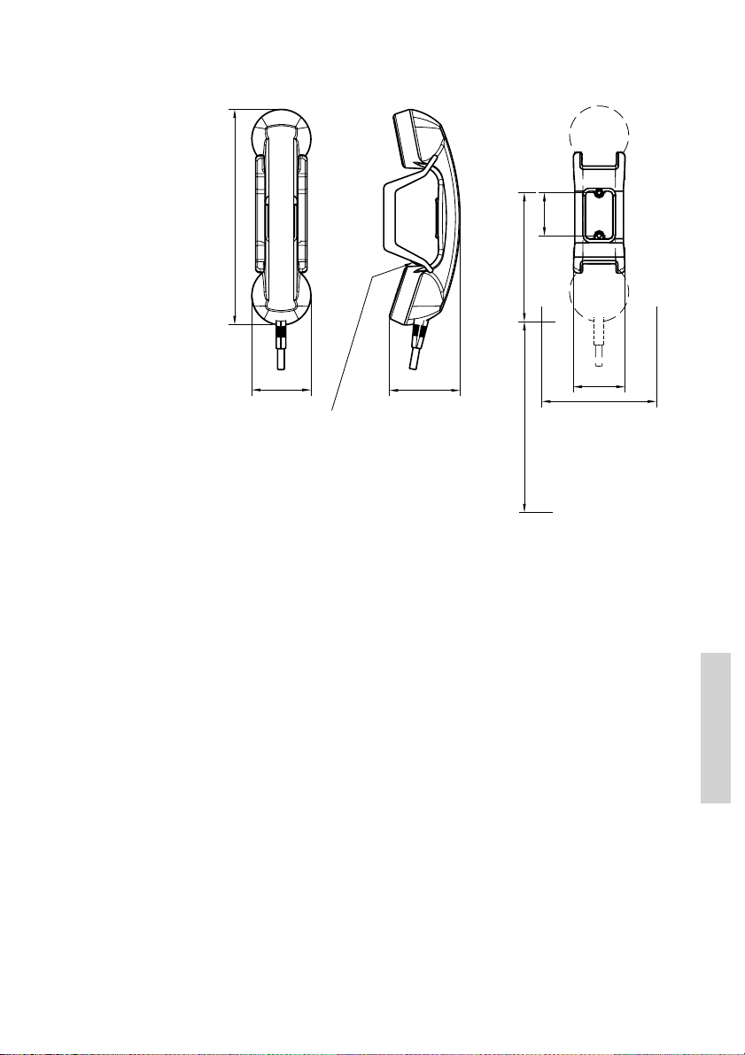
Handset for transceiver
Drilling plan
226
62
39655B
Weight
Handset for transceiver0.4 kg
75
This Handset has a hook-on/off function,
which is activated by a small magnet imbedded
in the ceadle.
The cradle must be installed as illustrated in
order to ensure the hook-on/off functionality
of the Handset.
45
135
Space for handset access
min. 200
Space for cable and handset cable
54
* 120
0605
Installation
43
Page 50
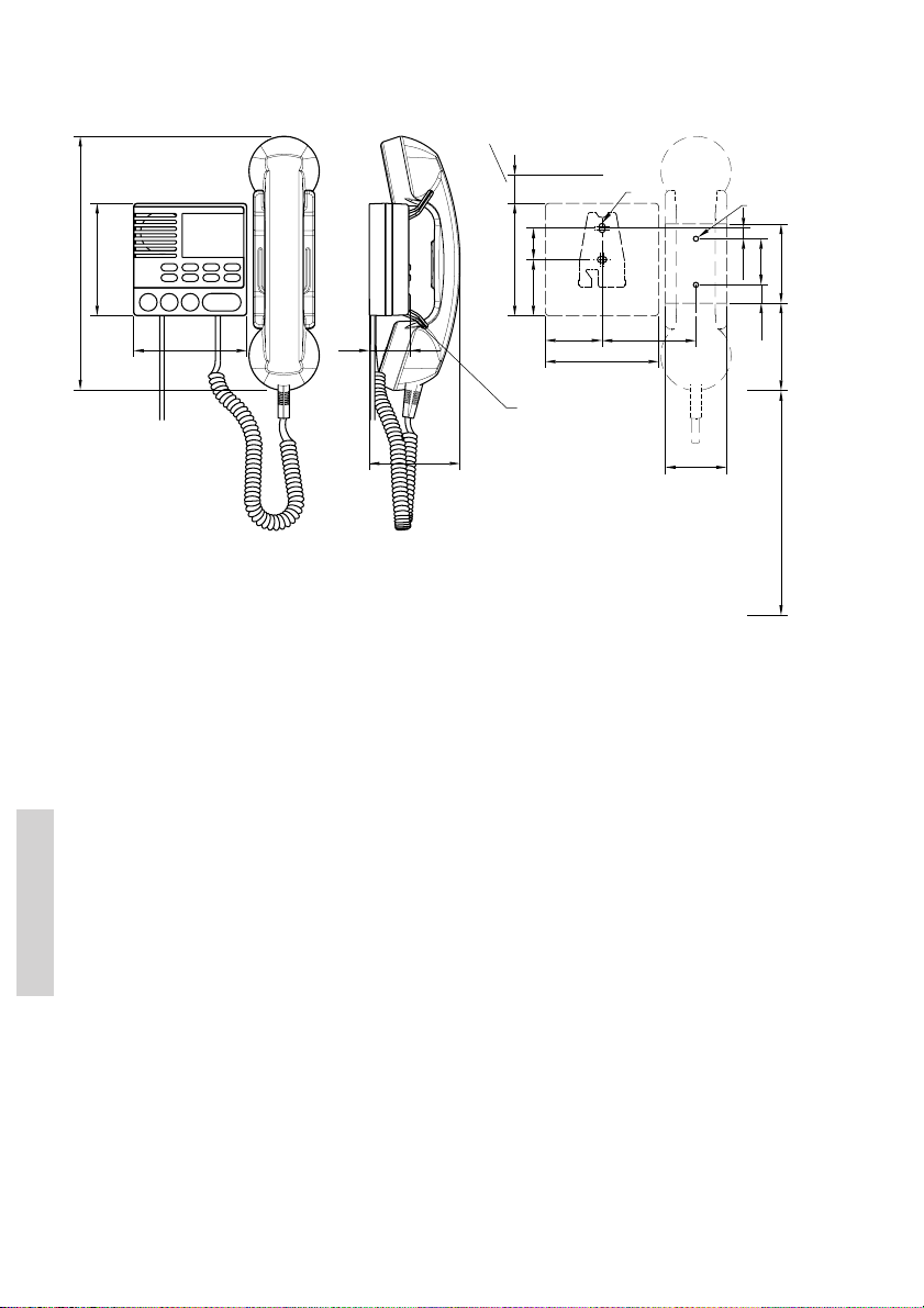
Semi-functional control unit
Space for installing and
detaching control unit
Drilling plan
2xø5
83
100
2xø4.5
41
9,6
16
54
226
39654C
100
100
Length of spiral cord
at rest : 380 mm
25
28
100
50
36
This Handset has a hook-on/off
function, which is activated
by a small magnet imbedded in
80
the cradle.
The cradle must be installed as
illustrated in order to ensure the
hook-on/off functionality of the
Handset.
50
Weight:
Semi-functional control unit 1.2 kg
Installing a single CU
After the CU is connected the unit can be operated straight away without any configuring.
Installation with 2 CUs
If an installation is carried out providing 2 new CUs, it is important when powering these up
for the first time, that this is done sequentially, to allow the CUs to acquire their individual
identity on the SPARC II bus:
70
78
min. 200
Space for cable and handset cable
2 newly installed CUs:
• Power on VHF
• Power on first CU
• Power on second CU
If an additional CU is installed in a system already working with a single CU, the
Installation
already existing CU must be switched on prior to the first power-on of the new CU.
Adding a CU in an installation already providing one CU:
• Power on VHF
• Power on the existing CU
• Power on the newly installed CU
This procedure is also followed if a CU is moved from another installation to this installation.
Always turn on the existing CU before turning on the last acquired one - when powering for
the first time after installation.
44
0605
Page 51
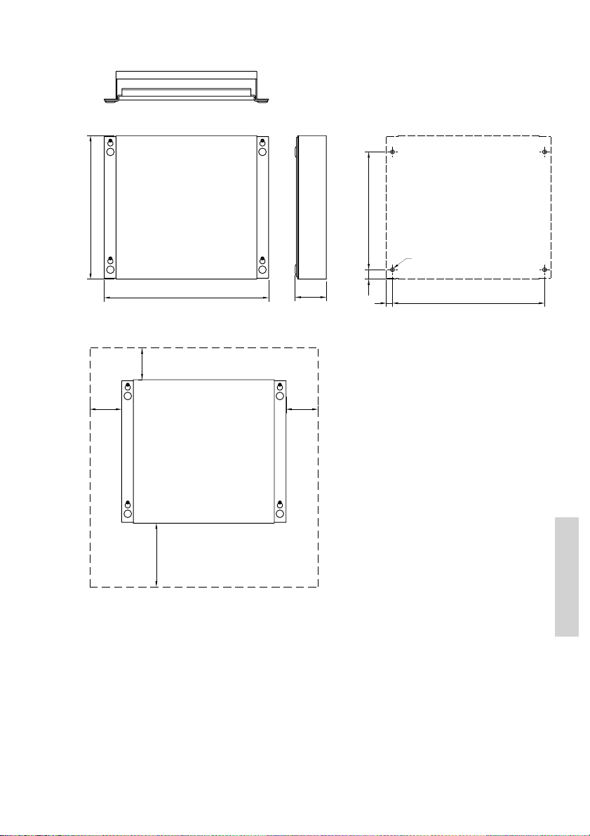
Connection box
Drilling plan
225.4
Mounting
* 50
185
4 pcs. ø6
* 50
49
14.85
2399.75
258.4
* 50
* Free space for mounting,
** Free space for cable entry.
** min. 100
39656
Weight
Connection box 1.7 kg
0605
Installation
45
Page 52
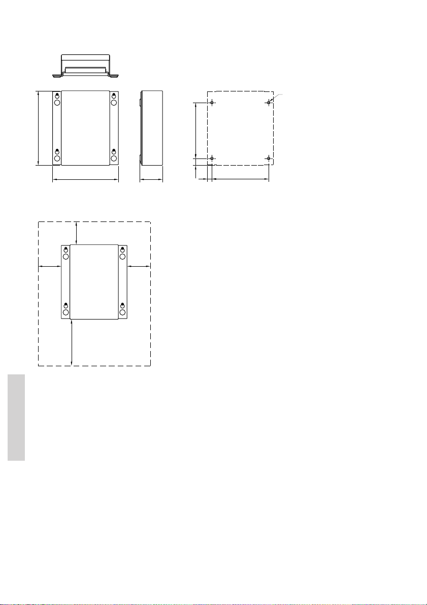
Extension box
Drilling plan
4 pcs. ø6
160.4
Mounting
39657
* 50
141.4
* 50
* Free space for mounting,
** Free space for cable entry.
** min. 100
* 50
120
49
14.85
Weight
Extension box 0.7 kg
9.7
122
Installation
46
0605
Page 53
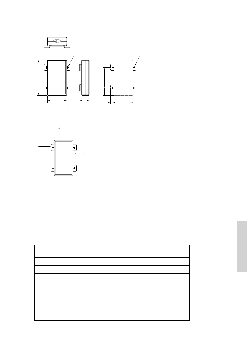
LAN box
126.5
Mounting
* 50
** Free space for cable entry.
** min. 100
39658
4xø4.5
74.5
100
* 50
* 50
* Free space for mounting,
Drilling plan
73
37
26.75
82
9
4xø3.5
Weight
LAN box 0.3 kg
9.2 Compass safe distance
Safe distance in accordance with Annex A of ISO 694:2000.
Safe distance bet w een t he nearest poi nt of t he i t em and the centr e
of the compass at which it wi ll produce a diviation of 0.3°
Device After m agne t ization
RT5022 Transceiver Unit 80 cm
C5001 Handset 85 cm
C5000 Semi-funct ional Contro l Unit 85 cm
CB5009 Connection Box 75 cm
EB Extension Box 55 cm
LB5007 LAN Box 30 cm
AP4365 Alarm Panel 50 cm
0622
Installation
47
Page 54
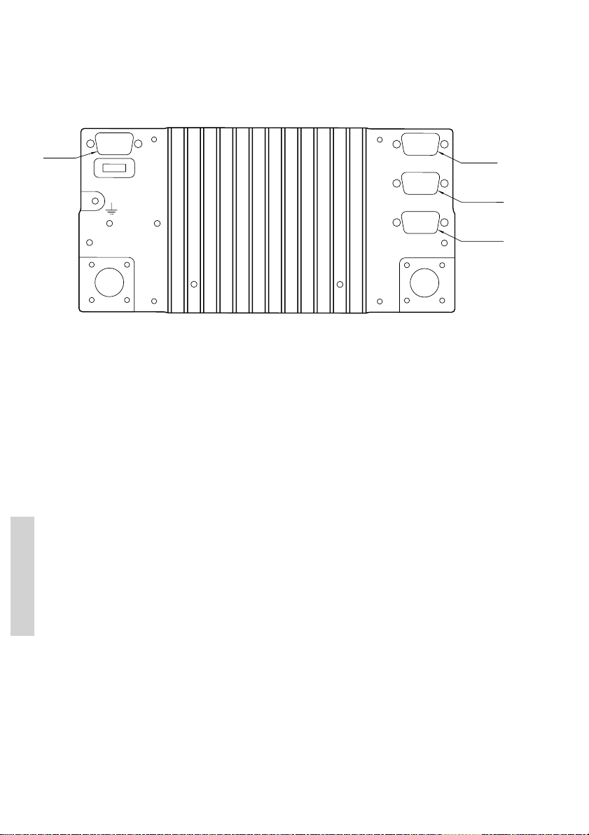
9.3 Interface connections
VHF (rear view)
Power
connector
39815A
FUSE
12-24V DC
Main Antenna
Option
Sparc II Bus
Handset
DSC Antenna
15-pin
sub D male
15-pin
sub D female
9 pin
sub D female
Installation
48
0622
Page 55
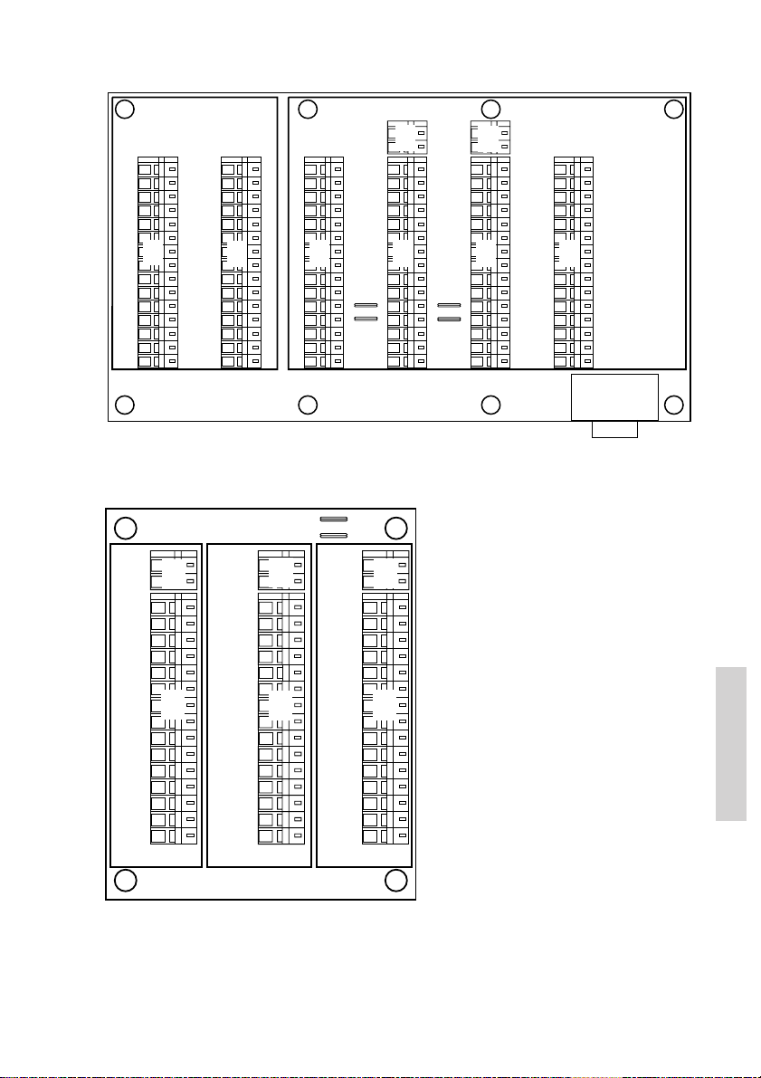
Connection box board 639121
X1
1
2
3
4
5
6
7
8
9
10
11
12
13
14
15
OPTIONS
39816B
RT50XX
OPTIONS
X1
OPTIONS
X2
VDR+
VDR-
AUX2
AUX2
AUX1
X2
AUX1
INT LS+
INT LS-
CALL
CALL
GND
NMEA+
NMEA-
ALARM
ALARM
CONNECTIONS
1
2
3
4
5
6
7
8
9
10
11
12
13
14
15
Extension board 639123
X6:
J1 & J2 MOUNTED = EXT LS
J1 & J2 NOT MOUNTED = CU LS
X4
X1
X5
EXT LS+
EXT LS-
X2
+12.5V
DATA+
DATA-
TX AF+
TX AF-
GND
+12.5V
RX AF+
RX AF-
+12.5V
EXT LS+
EXT LS-
GND
Line out
Line out
CB/RT50XX
X5
X2
X4
CU LS+
CU LS-
X1
1
2
3
4
5
6
7
8
9
10
11
12
13
14
15
CU
RT50XX
SPARC II
X3
SPARC II BUS
J1
J2
X6
EXT/CU
LS+
EXT/CU
LS-
X3
1
2
3
4
5
6
7
8
9
10
11
12
13
14
15
EB/CU
EXT /
CU LS
1
2
3
4
5
6
7
8
9
10
J1
J2
13
14
15
X8
X4X3
X6
X3
EB/CU
X8
X4
EB/CU
X9
X9
EXT /
CU LS
X5
1
2
3
4
5
X5
6
7
8
9
10
J3
J4
13
14
15
CONNECTIONS
IF CU IS CONNECTED TO
EB/CU TERMINALS THEN
REMOVE J1 & J2 FOR X4
AND J3 & J4 FOR X5
EXT
X6
1
2
3
4
5
X6
6
7
8
9
10
11
12
13
14
15
X7
LAN
INTERFACE
+12.5V
DATA+
DATA-
TX AF+
TX AF-
GND
+12.5V
RX AF+
RX AF-
+12.5V
EXT LS+
EXT LS-
GND
Line out+
Line out-
X7
Installation
0611
39817B
49
Page 56
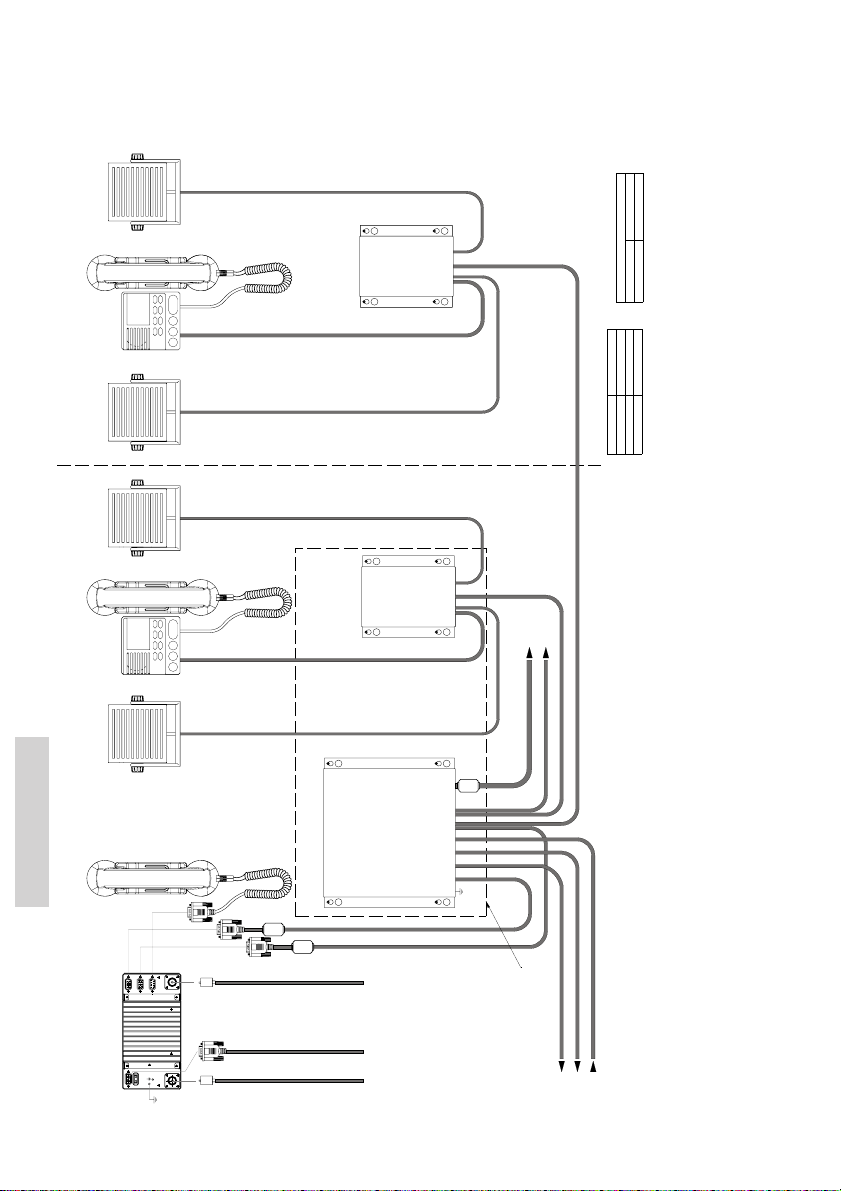
9.3.1 System block diagram with connection box and 2 x
extension box
Ext. speaker (VHF)
White
Black
CU 2 (Optional)
(Optional) (Optional)
Ext. speaker (CU)
(Optional)
Ext. speaker (VHF)
CU 1 (Optional)
(Optional)
Ext. speaker (CU)
Installation
Handset
Option
SPARC II bus
Handset
PL259
(Optional)
Extension Box
(Optional)
Extension Box
(Optional)
Connection Box
DSC Antenna
RG214 or better
L=3m
L=3m
L=5m
furnished with Connection Box
L=5m
furnished with Connection Box
furnished with LAN Box
To LAN Box (optional)
L=1.2m
Cable part no. 56.111
Cable part no. 539603
Cable part no. 56.114
.
(150W min. for RT5020)
Power connection 12-24VDC,
120W min. continuous
Maximum cable length
SPARC II cable length specification
Conductor size
2x2x0.5mm2, max 100m
To Alarm Panel - (if installed)
8x2x0.5mm2, max. 20m
8x2x0.5mm2, max. 20m
max 100m
1x2x0.5mm2
2x0.5mm2
NMEA
2x0.5mm2,
0 VDC
+ VDC
Power cable p/n 539826, 1.5m 2x4.0mm2
40m
30m
20m
8x2x0.5mm2
8x2x0.75mm2
8x2x1mm2
50
VHF
(rear view)
Ground
PL259
L=1.5m
furnished with equiptment
12-24V DC
RG214 or better
Cable
Power
RX/TX Antenna
(mixed Rx/Tx Audio)
To VDR
To ships alarm panel or announcer
From position sensor (GPS)
See next page:
Cable Connection diagram
All cabling not furnished with equipment to be overall screened type.
External power supply input is galvanically isolated from equipment ground reference, i.e. chassis.
Equipment internal power supply reference (-) is at equipment ground reference, i.e. chassis.
Cable screens must be securely grounded at cable inlets in connection boxes, as illustrated in cable connection diagrams.
Note:
39701C
0622
Page 57
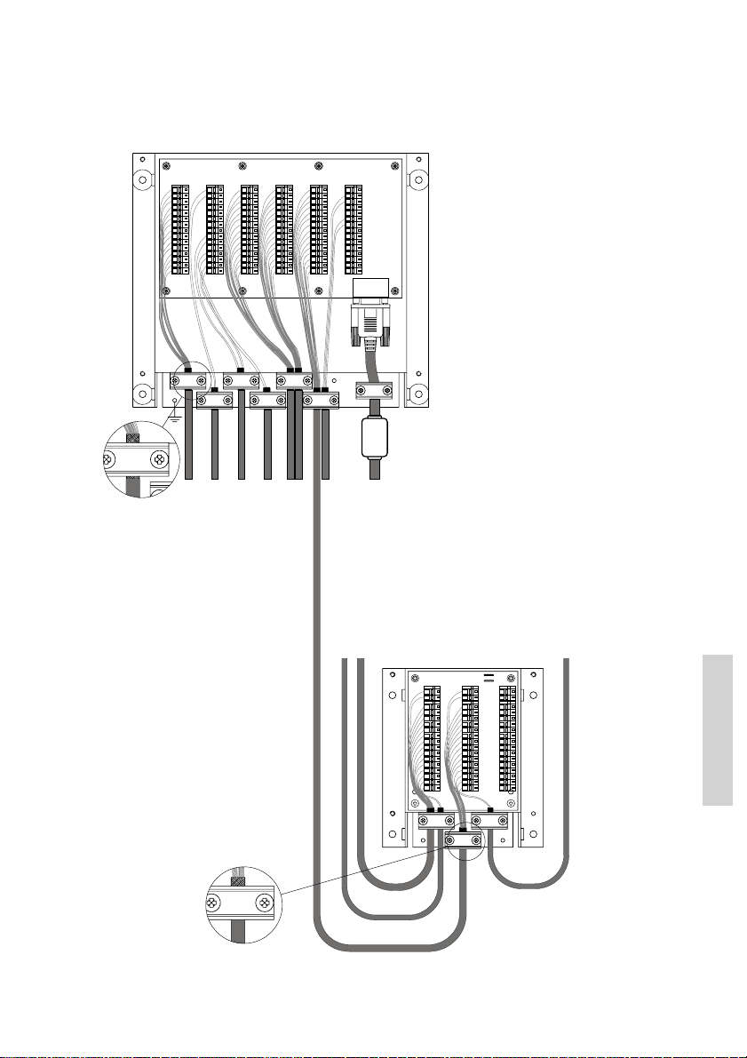
Cable connection diagram
CONNECTIONS CONNECTIONS
OPTIONS
RT50XX
OPTIONS
OPTIONS
X1
X2
VDR+
1
VDR-
2
AUX2
3
AUX2
4
AUX1
5
AUX1
6
EXT LS1
7
EXT LS1
8
CALL
9
CALL
10
GND
11
NMEA+
12
NMEA-
13
ALARM
14
ALARM
15
SPARC II BUS
RT50XX
EB/CU
SPARC II
X3
X4
X5
EXT /
EXT /
1
CU LS
CU LS
2
3
4
5
6
7
8
9
10
11
12
13
14
15
IF CU IS CONNECTED TO
EB/CU TERMINALS THEN
REMOVE J1 & J2 FOR X4
AND J3 & J4 FOR X5
EB/CU
EXT
X6
+12.5V
DATA+
DATA-
TX AF+
TX AF-
GND
+12.5V
RX AF+
RX AF-
+12.5V
EXT LS2
EXT LS2
GND
Line out+
Line out-
LAN
INTERFACE
X7
39734B
To VHF DSC
(mixed Rx/Tx Audio)
Cable part no. 539603
To VDR
NMEA
cable part no. 56.114
To extension box for CU2
To Alarm Panel - (if installed)
To VHF DSC
To ships alarm panel or announcer
From position sensor (GPS)
Cable part no. 56.111
To LAN interface (optional)
CU 1 (Optional)
Ext. speaker (CU)
X6 :
J1 & J2 MOUNTED = EXT LS
J1 & J2 NOT MOUNTED = CU LS
H2
X4
X4
CU LS+
CU LS-
X1
1
2
3
4
5
6
X1X3X2
7
8
9
10
11
12
13
14
15
H1
Ext. speaker (VHF)
J1
H3
J2
X5
X6
X5
X6
EXT/CU
EXT LS+
LS+
EXT/CU
EXT LS-
LS-
X3
X2
+12.5V
1
2
DATA+
DATA-
3
4
5
GND
6
+12.5V
7
8
9
10
+12.5V
LS+
11
12
LS-
13
GND
Line out
14
15
Line out
EB/CU
CB/RT50XX
CU
H4
Installation
0605
51
Page 58
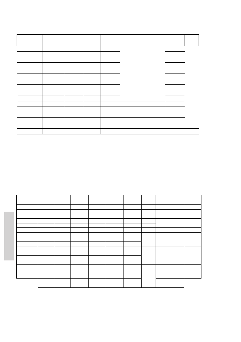
Interfaces
-
-
VHF Signal Cable Connection Connection Signal descri ption Ships cable
Options connector de signation p/n 539603 box box 8 twist ed pairs or
15-pin D-sub male
pin 1
VDR+ B rown
pi n 2 VD R- B ro wn/ W ht X1 -2 X2 -2
pin 3 AUX2 O range X1-3 X2-3
pin 4 AUX2 NO Orange/W ht X1-4 X2-4
pin 5 AUX 1 Blue X1-5 X2-5
pin 6 AUX 1 NO Blue/ Wht X1-6 X2-6
pin 7 int_Speak er + Green X1-7 X2-7
pin 8 int_Speaker - Green/W ht X1-8 X2-8
pin 9 DSC CALL Red X1-9 X2-9
pin 10 DSC CALL NO Red/Wht X1-10 X2-10
pin 11 GND
pin 12 NMEA + Y el X1-12 X2-12
pin 13 NME A - Yel /Wht or B lk X1-13 X2-13
pin 14 DSC ALARM Purple X1-14 X2-14 pair no. 7
pin 15 DSC ALARM NO Purpl e/Wht X1-15 X2-15 pai r no. 7
5m In from VHF E xternal conn. overall screen
X1- 1 X2- 1 pa ir no . 1
Blk+Blk/Wht X1-11 X2-11 Equipment ground
Mixed Rx /Tx audio output for
recording. Galvanically isolated,
balanced s ignal, 0dBm into 600Ω
Relay contact cl osing on event pre
defined through service
programming (s ee note 1)
Relay contact cl osing on event pre
defined through service
programming (s ee note 1)
VHF internal speaker output,
nom. 5W into 8Ω.
Relay cont act closi ng on incoming
DSC call (see note 1)
NMEA dat a input from external
posit ion sensor (see not e 2)
Relay cont act closi ng on incoming
Distres s alert (see note 1)
pair no. 1
pair no. 2
pair no. 2
pair no. 3
pair no. 3
pair no. 4
pair no. 4
pair no. 5
pair no. 5
pair no. 8
pair no. 6
pair no. 6
Housing Screen Chassis Chassis Screen Screens
Relay contact ratings (resistive load) Max. switched power: 30W or 60VA
Note 1:
Following NMEA sentences are supported: GLL, RMC, ZDA, GGA, VTG, GNS
Note 2:
Max. switched current: 1.0A
Max. switched voltage: 150VDC or 125VAC
in accordanc e with IEC61162-1
Sparc II Connections
Correspondingly grouped individual cabling
VHF Signal Cable Connecti on box Connection box Connection box Connection box Alarm panel Signal descript ion Ships cable
SPARC connec tor designation p/n 56.114 In from VHF Out t o CU1 or Out to CU2 or to alarm panel "VHF" 8 t wisted pairs
15-pin D-sub female
Installation
Housing Screen Chass is Chassis Chassis Chass is
NOTE:
jumpers J1/J2 and/ or J3/J4 in Connection Box mus t be removed in order to dis connect VHF Ext. Speaker (VHF LS) output from these term inals
and make available the CU Ext. Louds peaker (CU LS) connect ions instead.
12.5VDC+ Red/Wht
pin 1
pin 2 DATA_+
pi n 3 DAT A_- Y el /W ht X3- 3 X4 -3 X5 -3 X6- 3 5
pin 4 TX_AF+ Blue/W ht X3-4 X4-4 X5-4 X6-4
pin 5 TX_AF - Blue X3-5 X4-5 X5-5 X6-5
pin 6 GND Orange + Red X3-6 X4-6 X5-6 X6-6 2 Equipment ground
pin 7 12.5VDC+ Orange/Wht X3-7 X4-7 X5-7 X6-7 9 Power to CUs
pin 8 RX_AF+ Green/Wht X3-8 X4-8 X5-8 X6-8
pi n 9 RX_ AF- Gr een X3 -9 X4- 9 X5 -9 X6- 9
pin 10 12.5VDC+ Blk /Wht X3-10 X4-10 X5-10 X6-10 Power to CUs
pin 11 EXT.Speaker + Brown X3-11 X4-11 X5-11 X6-11
pin 12 EXT.Speaker - Brown/Wht X3-12 X4-12 X5-12 X6-12
pin 13 GND Blk X3-13 X4-13 X5-13 X6-13 E quipment ground
pin 14 Lineout + Purple X3-14 X4-14 X5-14 X6-14 pair no. 5
pin 15 Lineout - Purple/ Wht X3-15 X4-15 X5-15 X6-15 pair no. 5
EXT LS X8 -1 X9- 1
EXT LS X8 -2 X9- 2
In case of c onnecting CU1 and/or CU2 direct ly to Connec tion Box, i.e. not utilizing Extens ion Box for connecting eac h CU,
5m extensi on box ext ension box connect or X3 overall screen
X3- 1 X4 -1 X5- 1 X6- 1 Po wer to C Us p air no. 8
Yel
X3- 2 X4- 2 X5 -2 X6 - 2 3
SPA RC II-bus Data
SPARC II-bus Tx audio
SPARC II-bus Rx audio
VHF radio external
speaker output, nom. 5W
into 8Ω
Rx-audio line output,
balanced signal, 0dB m
into 600Ω
External s peaker output,
nom. 5W int o 8Ω (
NOTE
se e
)
52
pair no. 1
pair no. 1
pair no. 2
pair no. 2
pair no. 6 & 8
pair no. 6
pair no. 3
pair no. 3
pair no. 7
pair no. 4
pair no. 4
pair no. 7
Screen
0611
Page 59
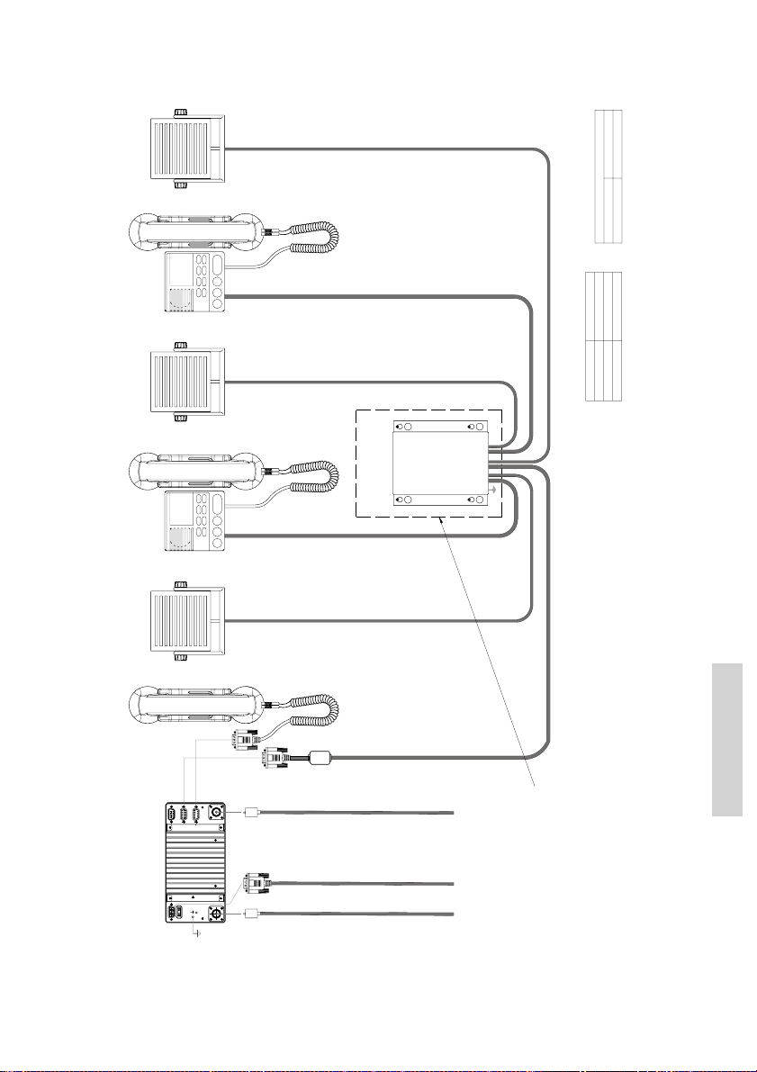
9.3.2 System block diagram with extension box
SPARC II bus
Handset
(Optional) (Optional)
Ext. speaker (CU1)
Ext. speaker (CU2)
CU 1 (Optional)
39702C
CU 2 (Optional)
(Optional)
Ext. speaker (VHF)
(Optional)
Extension Box
Note:
SPARC II cable length specification
Conductor size
Maximum cable length
8x2x0.5mm2
20m
8x2x0.75mm2
30m
8x2x1mm2
40m
All cabling not furnished with equipment to be overall screened type.
Cable screens must be securely grounded at cable inlets in connection boxes,
120W min. continuous
Power cable p/n 539826, 1.5m 2x4.0mm2
+ VDC
White
0 VDC
Black
(rear view)
56.114
L=5m
VHF
DSC Antenna
RG214 or better
PL259
RX/TX Antenna
RG214 or better
PL259
Power
12-24V DC
Cable part no. 539826
L=1.5m
furnished with equiptment
L=3m
Cable Connection diagram
See next page:
Power connection 12-24VDC,
External power supply input is galvanically isolated from equipment ground reference, i.e. chassis.
Equipment internal power supply reference (-) is at equipment ground reference, i.e. chassis.
as illustrated in cable connection diagrams.
L=3m
(150W min. for RT5020)
Installation
0622
53
Page 60
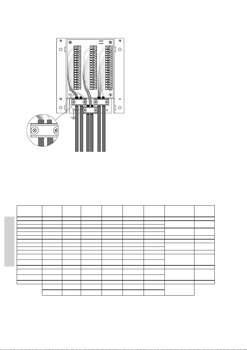
Cable connection diagram
r
X6 :
J1 & J2 MOUNTED = EXT LS
H2
J1 & J2 NOT MOUNTED = CU LS
X5
X4
X4
CU LS+
EXT LS+
CU LS-
EXT LS-
X1
X2
+12.5V
1
DATA+
2
DATA-
3
TX AF+
4
TX AF-
5
GND
6
X1X3X2
+12.5V
7
RX AF+
8
9
RX AF-
10
+12.5V
LS+
11
LS-
12
13
GND
Line out
14
15
Line out
CU
H1
CU 1 (Optional)
39735
Ext. speaker (CU)
J1
J2
X6
X5
EXT/CU
LS+
EXT/CU
LS-
X3
10
12
13
14
15
VHF
VHF DSC
CU 2 (Optional)
Ext. speaker (VHF)
H3
X6
1
2
3
4
5
6
7
8
9
10
11
12
13
14
15
CU/CB
H4
Ext. speaker (CU2)
VHF Si gnal Cable Ext ension box Extension box Cable integrated E xtension box Signal desc ription Ships cabl e
SPARC II connect o
15-pin D-sub f emale
pin 1 12.5V DC+ Red/ Wht X2-1 X1-1 Red/ Wht X3-1 P ower to CUs pair no. 8
pin 2 DATA_+ Yel X2-2 X1-2 Yel X3-2 pair no. 1
pin 3 DATA_- Yel/ Blk X2-3 X1-3 Yel/ Blk X3-3 pair no. 1
pin 4 TX_A F+ Blue/W ht X2-4 X1-4 Blu/Wht X3-4 pair no. 2
pin 5 TX_AF- Blue X2-5 X1-5 Blu X3-5 pair no. 2
pin 6 GND Orange + Red X2-6 X1-6 O range + Red X3-6 Equipment ground pair no. 6 & 8
pin 7 12.5VDC+ Orange/Wht X2-7 X1-7 Orange/ Wht X3-7 Power t o CUs pair no. 6
pin 8 RX_AF+ Green/Wht X2-8 X1-8 Grn/Wht X3-8 pair no. 3
pin 9 RX_AF- G reen X2-9 X1-9 Grn X3-9 pair no. 3
pin 10 12.5VDC+ Blk/ Wht X2-10 X1-10 B lk/Wht X3-10 Power to CUs pair no. 7
pin 11 EXT.Speaker + Brown X2-11 X1-11 Brn X3-11 pair no. 4
Installation
pin 12 EXT.Speaker - Brown/Wht X2-12 X1-12 Brn/ Wht X3-12 pair no. 4
pin 13 GND Blk X2-13 X1-13 Blk X3-13 E quipment ground pair no. 7
pin 14 Lineout + Purple X2-14 X1-14 Purple (NC) X3-14 pair no. 5
pin 15 Li neout - Purple/ Wht X2-15 X1-15 P urple/Wht (NC) X3-15 pair no. 5
Housing Screen Chass is Chassis Sc reen Chassi s Screen
In case of connect ing a second CU (CU2) to the Extens ion Box, jumpers J1/ J2 should be removed in order to dis connect VHF
NOTE:
Ext . Speaker (VHF LS) out put from terminals X6-1/2 and make available the CU2 Ex t. Speaker (CU2 LS) connec tions instead.
VHF Ext. Speaker output will be available at terminals X5-1/2.
Connecting only one CU (CU1) and leaving jumpers J1/J2 in circuit provides VHF Ext . Speaker connecti on avai lable at both X5-1/2 and X6-1/2.
designation p/n 56.114 In from VHF Out to CU1 with CU Out t o CU2 8 twist ed pairs
or conn. Box overall screen
SPA RC II-bus Data
SPARC II-bus Tx audio
SPA RC II-bus Rx audio
VHF radio ext ernal
speaker output , nom.
5W into 8Ω
Rx-audio line output ,
balanced si gnal, 0dBm
into 600Ω
EXT LS
EXT LS
(VHF LS out: X5-1) CU1 LS out: X4-1 CU2 LS out: X6-1
(VHF LS out: X5-2) CU2 LS out: X4-2 CU2 LS out: X6-2
External speaker
output, nom . 5W into
8Ω (
see NOTE
)
54
0611
Page 61

9.4 Power supply
The VHF should be powered from a separately fused DC-supply of 10.8 - 32VDC and rated
at minimum 120W continuous power for installations with RT5022 (Simplex/semi-duplex),and
150W for installations with the RT5020 (Duplex)
9.5 Antenna installation and precautions
9.5.1 Antennas
The VHF equipment requires two antennas installed one for the DSC receiver and the other
(Primary) for the VHF RX/TX communication.
All commonly available 50Ω antennas covering the appropriate frequency range and
providing a VSWR less than 1.5 over this range may be used.
The antennas should be connected using a low loss type 50Ω coaxial cable, e.g. good
quality RG214 or better.
IMO-COMSAR/Circ. 32 recommends the use of a double screened type cable (like e.g.
RG214) with a maximum insertion loss of 3dB across the antenna cable installation. The
maximum antenna cable length in the installation thus depends on the quality of the cable
used, i.e. the specified attenuation (dB/m) of the cable of choise at the high end of the VHF
frequency band. As a rule of thumb the cable length using e.g. RG214 coaxial cable should
not exceed 25m.
For further details on equipment/antenna installation, reference is made to the IMOCOMSAR/Circ. 32, GUIDELINES FOR THE HARMONIZATION OF GMDSS REQUIREMENTS FOR RADIO INSTALLATIONS ON BOARD SOLAS SHIPS.
9.5.2 RX/TX antenna
In installations consisting of two or more VHF radios it is important to ensure the optimum
performance of these by carefully selecting the mutual antenna positions.
In general the highest possible RF attenuation between the VHF RX/TX antennas in the
installation should be sought for. The most important parameter in achieving this is by
ensuring that none of the RX/TX antennas in the installation are positioned at the same
horizontal level, i.e. the RX/TX antennas must be installed at shifted elevations as indicated
below.
In situations where sufficient vertical distance between two or more such antennas is found
difficult to obtain the horizontal distance between them will play an increasingly important
role in the equipment performance the less the vertical separation and as a minimum 5m
horizontal distance between any RX/TX antennas in the installation should be ensured.
Additionally, in order to minimize any increase in VSWR of the VHF RX/TX antenna this
should be installed in a distance no closer to any other mast/pole object or other RF antennas than 2 m.
To the widest possible extend the VHF antennas should be kept out of the antenna main
beam of any radar and satellite equipment.
0622
Installation
55
Page 62
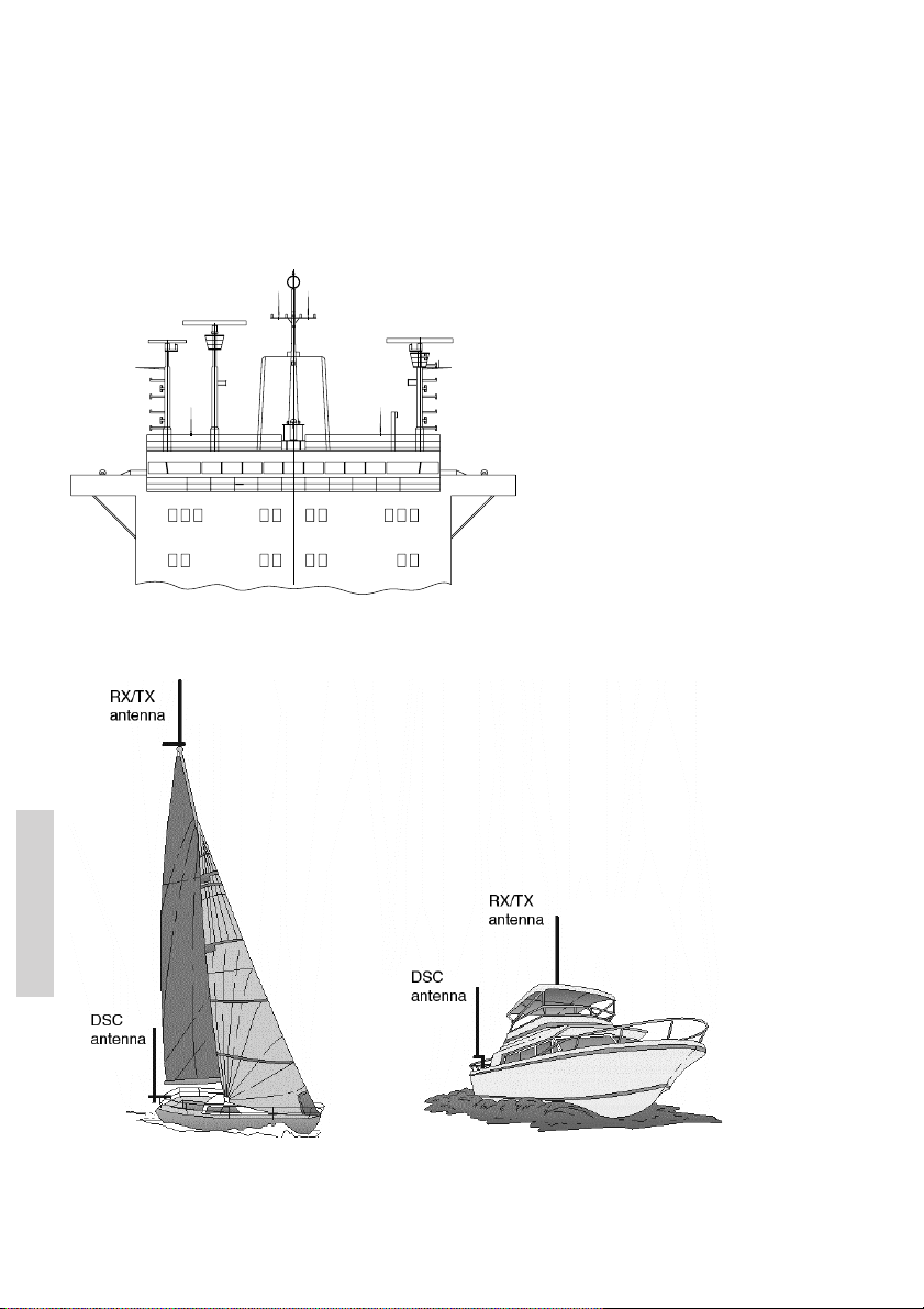
9.5’.3 DSC antenna
The positioning of the DSC antennas is less critical in terms of the imposed VSWR and due
to the nature of the DSC-signalling. It should be noted however, that the DSC receiver of a
VHF is likely to be temporarily blocked in reception due to high signal blocking, if the
associated DSC antenna is installed in close vicinity of a RX/TX antenna at the same
horizontal level while transmission takes place from this RX/TX antenna.
Example of VHF antenna arrangement.
No. 1 VHFNo. 2 VHF
RX/TX
No. 2 VHFNo. 1 VHF
RX/TX
39679
DSC
DSC
Installation
Example of VHF antenna arrangement
56
0622
Page 63

10 Technical specifications
10.1 General information
Channel Tables 4 pre-programmed channel tables covering the following
Private Channels Up to 30 private channels in 3 separate banks (designated F,
Channel spacing 25 kHz / optional 12.5 kHz
Contact List User programmable with up to 200 entries for easy DSC
Scanning Priority scanning. All channels or scanning up to 3 user
Voice replay Voice replay facility of up to 90 seconds of received voice
Automatic squelch Automatic squelch adjustment with memory function.
Readout Dimming facility for better sight at night.
10.2 General DSC facilities
DSC operation According to Rec. ITU-R M.541-9
DSC protocol According to Rec. ITU-R M.493-11 Class A
Navigator interface According to IEC 61162-1
Symbol error rate
Below 1x10
Modulation 1700 Hz ± 400 Hz
Frequency error below ± 1 Hz
Residual modulation below –26 dB
-2
regions:
• International waters - according to radio regulations
• US waters – according to radio regulations
• Inland waters (with ATIS) – according to radio
regulations
• Canadian waters – covering most areas
P and L)
per channel table (country region). Each bank contains up to
10 private
channels. For US and CA regions designated weather
channels are preconfigured, occupying some of the private channel storage
capacity.
radiotelephony initiation.
programmable scan tables in each channel mode.
data.
and Rec. ITU-R M.689-2
GLL, RMC, ZDA, GGA, VTG, GNS
-121 dBm or 0.20 µV p.d.
1200 baud
10.3 Specific data for transceiver unit RT5022
Frequency range Rx / Tx:149.300 - 163.750 MHz
Operation modes Simplex / Semiduplex
Modulation G3EJN for Telephony
G2B for DSC.
Frequency stability below ± 3 ppm
Aerial connectors Standard 50 ohm female SO239
Temperature range -15 °C to +55 °C
0611
Installation
57
Page 64

Supply voltage 12V to 24V DC nominal
Supply range 10.8V to 31.2V DC
Power requirements-Tx Min. 120W continous
Power requirements-Rx(w.2CUs) Max 25W
Power requirements-Rx(stand alone) Max 15W
Transceiver dimensions H*W*D 100*200*210 mm
Transceiver weight 4.1 Kg
Receiver
Sensitivity for 20 dB SINAD
CCITT weighted -121 dBm typical
AF rated Power
Internal L.S. 5 Watt in 8 ohm
Output for External L.S. 5 Watt in 8 ohm
Distortion below 5 %
S/N ratio more than 43 dB
Spurious emission below 0.25 nW
Spurious response rejection more than 74 dB
Intermodulation response more than 73 dB
Co- channel rejection better than –10 dB
Adjacent channel selectivity more than 74 dB
Blocking level more than 94 dBìV
Transmitter
RF output power
High 25W +0dB to –0.5dB
Low 0,85 W +0.5dB to –1dB
Adjacent channel power below 75 dB
Conducted spurious emission below 0.25 mW
Distortion below 3 %
S/N ratio better than 46 dB
10.4 Specific data for transceiver unit RT5020
Frequency range Rx / Tx:150.800 - 157.425 MHz
Operation modes Simplex / Duplex
Modulation G3EJN for Telephony
Frequency stability below ± 3 ppm
Aerial connectors Standard 50 ohm female SO239
Temperature range -15 °C to +55 °C
Supply voltage 12V to 24V DC nominal
Supply range 10.8V to 31.2V DC
Installation
Power requirements-Tx Min. 120W continous
Power requirements-Rx(w.2CUs) Max 25W
Power requirements-Rx(stand alone) Max 15W
Transceiver dimensions H*W*D 100*200*210 mm
Transceiver weight 4.9 Kg
58
Rx: 160.625 – 163.600 MHz
G2B for DSC
0605
Page 65

Receiver
Sensitivity for 20 dB SINAD
CCITT weighted -119 dBm typical
Duplex spurious response att. More than 74 dB
Duplex desentization below 3 dB
AF rated Power
Internal L.S. 5 Watt in 8 ohm
Output for External L.S. 5 Watt in 8 ohm
Distortion below 5 %
S/N ratio more than 43 dB
Spurious emission below 0.25 nW
Spurious response rejection more than 74 dB
Intermodulation response more than 73 dB
Co- channel rejection better than –10 dB
Adjacent channel selectivity more than 74 dB
Blocking level more than 94 dBìV
Transmitter
RF output power
High 25W +0dB to –0.5dB
Low 0.85 W +0.5dB to –1dB
Adjacent channel power below 75 dB
Conducted spurious emission below 0.25 mW
Distortion below 3 %
S/N ratio better than 46 dB
0602
Installation
59
Page 66

DECLARATION OF CONFORMITY
Thrane & Thrane A/S
Porsvej 2
9200 Aalborg SV
DK-Denmark
We as manufacturer herewith declare that the following equipment complies with the
specifications of the Marine Equipment Directive 96/98/EC & the amending Directive 2002/75/
EC, A.1/5.1: A.1/5.2
Equipments
SAILOR RT50xx VHF Radiotelephone with DSC Controller & Ch 70 Watch Keeping Receiver
Consisting of:
Equipment Applicability
SAILOR RT5022 is a simplex/semi duplex VHF radiotelephone, and SAILOR RT5020 is a full
duplex VHF radiotelephone, both designed for maritime communication within the Global
Maritime Distress and Safety System, GMDSS, with DSC capability.
SAILOR RT5022 and SAILOR RT5020 are able to operate on all international VHF channels.
RT5022 Main Transceiver Unit, simplex, semi-duplex
RT5020 Main Transceiver Unit, duplex
HS5001 Handset
CU5000 Remote Control Unit
CB5009 Connection Box
EB5008 Extension Box
LB5007 LAN Box
SB5006 Service Box
AP4365 Alarm Panel
Declaration
SAILOR RT5022 and SAILOR RT5020 conform to the Maritime Equipment Directive 96/98 EC and
2002/75 EC which is shown by conforming to the Harmonised standards EN60945 regarding
environmental requirements, EN301925 regarding spectrum matters and EN300338 regarding
Digital Selective Calling, DSC.
SAILOR RT5022 also conforms to FCC rules part 80. FCC ID: TCORT5022
SAILOR RT5020 also conforms to FCC rules part 80. FCC ID: TCORT5020
Certificate no.
MED 96/98 EC Module D certificate - MED-D-771 Notified Body DNV 0575
Telefication 05212002/AA/03
Telefication 05218052/AA/00
Telefication 05218114/AA/00
01.02 - 2006
Date
Doc. no 39861F00
Chief Executive Officer
Henrik Lunde
Page 67

Page 68

Thrane & Thrane A/S • [email protected] • www.thrane.com
 Loading...