

Sailor RT2048 VHF Installation Manual
INSTALLATION MANUAL
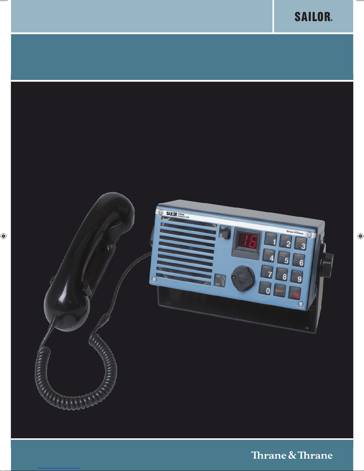
SAILOR RT2048 VHF

Disclaimer
Any responsibility or liability for loss or damage in connection with the use of this product and the accompanying documentation is disclaimed by Thrane & Thrane. The information in this manual is provided for information
purposes only, is subject to change without notice, may contain errors or inaccuracies, and represents no commitment whatsoever by Thrane & Thrane. This agreement is governed by the laws of Denmark.
Manuals issued by Thrane & Thrane are periodically revised and updated. Anyone relying on this information
should satisfy himself/herself as to the most current version. Providers with access to Thrane & Thrane’s Extranet may obtain current copies of manuals at: http://extranet.thrane.com.
Thrane & Thrane is not responsible for the content or accuracy of any translations or reproductions, in whole or
in part, of this manual from any other source.

RT2048
CONTENTS
1. INTRODUCTION 1-1
1.1. GENERAL DESCRIPTION 1-2
1.2. TECHNICAL DATA 1-3
1.3. CONTROLS 1-4
1.4. PRINCIPLE OF OPERATION 1-6
2. INSTALLATION 2.1
2.1. MOUNTING POSSIBILITIES 2-2
2.2. HANDSET 2-6
2.3. MICROTELEPHONE CONNECTOR 2-6
2.4. POWER SUPPLY 2-6
2.5. POWER CONNECTOR + EXT. LOUDSPEAKER 2-7
2.6. ANTENNAS 2-7
2.7. SPECIAL OPTIONS 2-7
2.8. REAR VIEW OF VHF RT2048 2-11
2.9. STANDARD FREQUENCY TABLE 2-12
3. SERVICE 3-1
3.1. MAINTENANCE 3-1
3.2. ALIGNMENT INSTRUCTIONS 3-1
3.3. PROPOSAL FOR NECESSARY MEASURING INSTRUMENTS 3-1
3.4. TEST PROBE 3-2
3.5. ADJUSTMENT PROCEDURE 3-2
3.6. TROUBLESHOOTING 3-3
3.7. REPLACEMENT OF COMPONENTS 3-4
3.8. REPLACEMENT OF MODULES 3-4
3.9. NECESSARY ADJUSTMENTS AFTER REPLACEMENT
OF MODULE 3-4
3.10. PIN CONFIGURATIONS 3-5
4. MODULE LOCATION 4-1
4.1. MECHANICAL DISASSEMBLING RT2048 4-2
5. CIRCUIT DESCRIPTION AND SCHEMATIC DIACRAMS 5-1
5.1. KEYBOARD UNIT (MODULE 1) 5-1
5.2. INTERFACE UNIT (MODULE 2) 5-3
5.3. SYNTHESIZER UNIT (MODULE 3) 5-6
5.4.
5.5.
5.6. INTERCONNECTION CABLE DIAGRAM
6. MICROTELEPHONE INSTALLATION 6-1
6.1. SPECIAL INSTALLATION WITH 2 MICROTELEPHONES 6-3
6.2. SPECIAL INSTALLATION WITH 3 MICROTELEPHONES 6-4
6.3. MECHANICAL DIMENSIONS FOR HANDSET 6-5
7. PARTS LIST 7-1
Appendix A - ATIS OPTION (OPTIONAL)
Rx/Tx UNIT (MODULE 4) 5-12
SELCALL UNIT (MODULE 5) OPTIONAL 5-18
5-20
0820

0820
Page 1-1
RT2048
1. INTRODUCTION
The RT2048 VHF radiotelephone has been designed to comply with the increasing demands of a highly technological
product, which means high quality, small size, etc.
The RT2048 is furthermore designed to fit into the Compact 2000 module programme.
The RT2048 can either be installed and operated as an independent unit, or in combination with other elements of
the Compact 2000 programme. These include a Duplex VHF radiotelephone, a coast telephone station with a 400W
PEP SSB transmitter and an SSB receiver with built-in FM and AM bands, and a scrambler which ensures complete
communication secrecy.
The VHF RT2048 has, by means of the latest technology in casting technique, been constructed to withstand the
most extreme conditions experienced in small, semi-open boats. The printed circuits inside are designed with a high
degree of compactness and exceptional performance.
In the design of this VHF radiotelephone, Thrane & Thrane have taken into account all the circumstances it will be
exposed to in day-to-day operation. However, even a product of this high quality requires regular servicing and
maintenance, and we recommend a close observance of the directions contained in the instruction book.
Thrane & Thrane is one of Europe’s leading producers of maritime radio communication equipment - a position which
has been maintained by means of constant and extensive product development. We have a world-wide network of
dealers with general agencies in fifty countries. All our dealers are well-trained and able to service all Thrane & Thrane
products.

1 INTRODUCTION RT2048
1.1. GENERAL DESCRIPTION
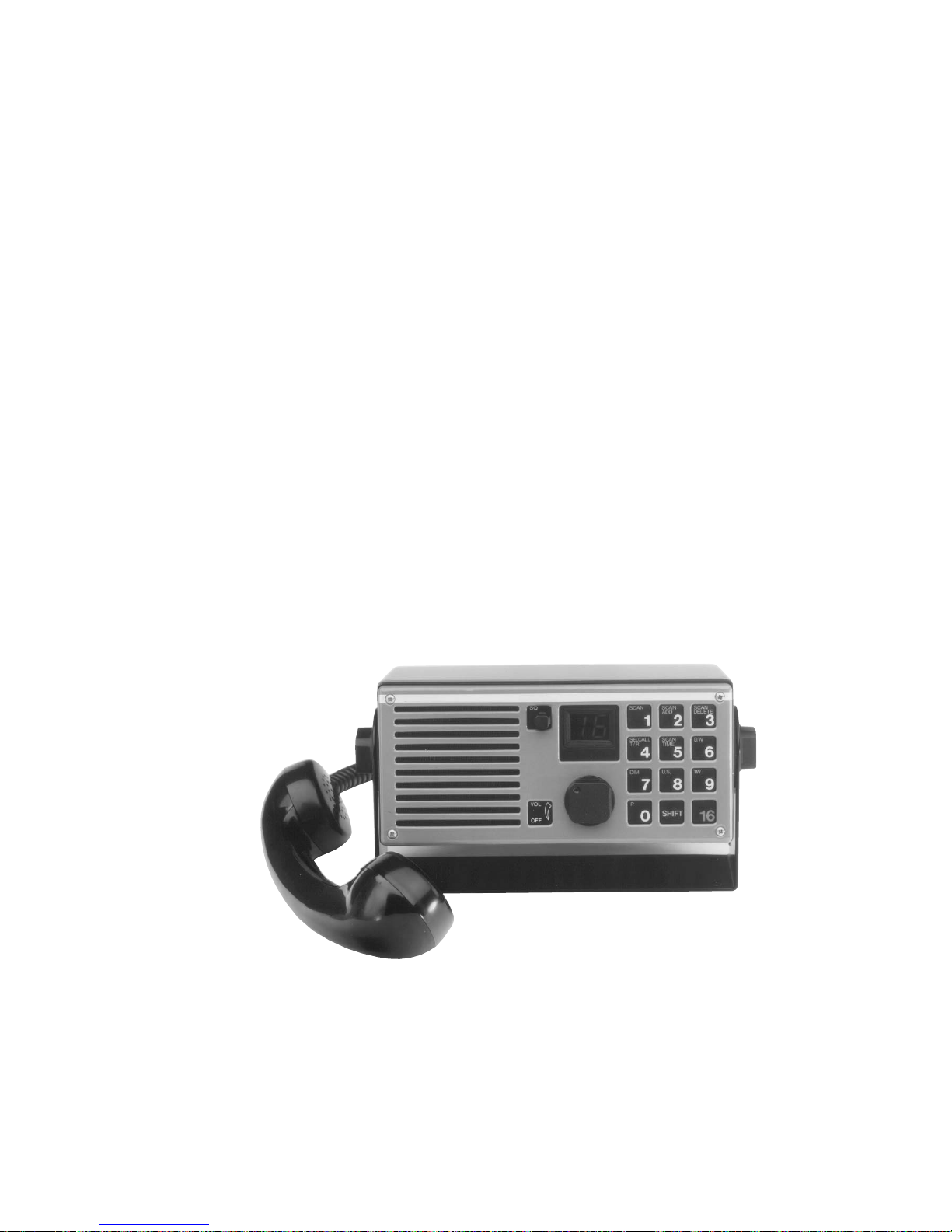
VHF RT2048 is an all solid state constructed microcomputer controlled VHF radiotelephone, intended for ship/ship
and ship/shore communication.
VHF RT2048 can operate in both simplex and semi-duplex mode.
VHF RT2048 includes all 55 international and U.S. VHF marine channels, and is as standard prepared for up to 10
private channels, selected as simplex or semi-duplex channels in the frequency band 154.4 -
163.75 MHz.
VHF RT2048 is equipped with flexible scanning facilities or additional 30 private channels in the above mentioned
frequency band.
VHF RT2048 has built-in dual watch facility, which enables the operator to listen out on two channels simultaneously
(the selected channel and a programmable preference channel - normally channel 16).
VHF RT2048 is provided with a quick select channel, normally channel 16.
VHF RT2048 is provided with continuous turn-style operation of SQ and AF level for optimum resolution.
VHF RT2048 is provided with a push-button keyboard offering an attractive tactile feeling and a safe finger-guide in
the metal front. Besides, the keyboard is fitted with night-illumination of the lettering from behind.
VHF RT2048 has a high efficient LED read-out of channel number and other indications for optimum reading under
all conditions.
VHF RT2048 is a modern transceiver with an all synthesized frequency generation based on a single crystal.
VHF RT2048 has a built-in 12W AF power amplifier, which delivers 6W into the large built-in loudspeaker.
VHF RT2048 is for 12V DC supply. Voltage change-over from 24V to 12V is easily done by the power supply N420.
VHF RT2048 has an extremely low standby current consumption, typically below 100 mA.
VHF RT2048 is housed in a corrosion resistant metal cabinet with a green nylon finish.
VHF RT2048 can be delivered with a built-in selcall decoder, which will decode a selective call CA or all ships call
CQ
9403
Page 1-2

1 INTRODUCTION RT2048
9403
Page 1-3
1.2. TECHNICAL DATA
Fulfils the international CEPT regulations.
GENERAL
All international maritime VHF channels
Private channels: 10, may be extended to 40
Operation: Simplex and semi-duplex
Modulation: G3EJN (Phase)
Antenna impedance: 50 ohm
Frequency stability: +/- 10 ppm (Spec. vers. +/- 5 ppm)
Temperature range: -20oC to +55oC
Nominal power supply: 13.2V DC
Power supply variation: 12V DC -10% to +30%
(with data according to international standards)
Power consumption: Standby = 0.1 A
Transmit = 5 A
Dimensions: Height: 98 mm
Width: 225 mm
Depth: 160 mm
Weight: 3.1 kg
RECEIVER
Frequency range simplex: 154.40 - 159.15 MHz
Frequency semi-duplex: 159.00 - 163.75 MHz
Sensitivity: 0.25 uV PD at 12 dB SINAD
AF output power: 6 Watt/4 ohm
Telephone output: 0.5V RMS/200 ohm
Distortion: Less than 5%
Scanning facilities: Flexible scanning programme,
with possibility for all international
channels and 10 private channels.
Accessory: Selcall decoder according to
CCIR
TRANSMITTER
Frequency range normal: 154.40 - 159.15 MHz
Frequency range special: 159.00 - 163.75 MHz
RF output power: 25 Watt +0 to -0.5 dB
Reduced RF output: 0.5 to 1 Watt
Distortion: Less than 5%
1 INTRODUCTION RT2048
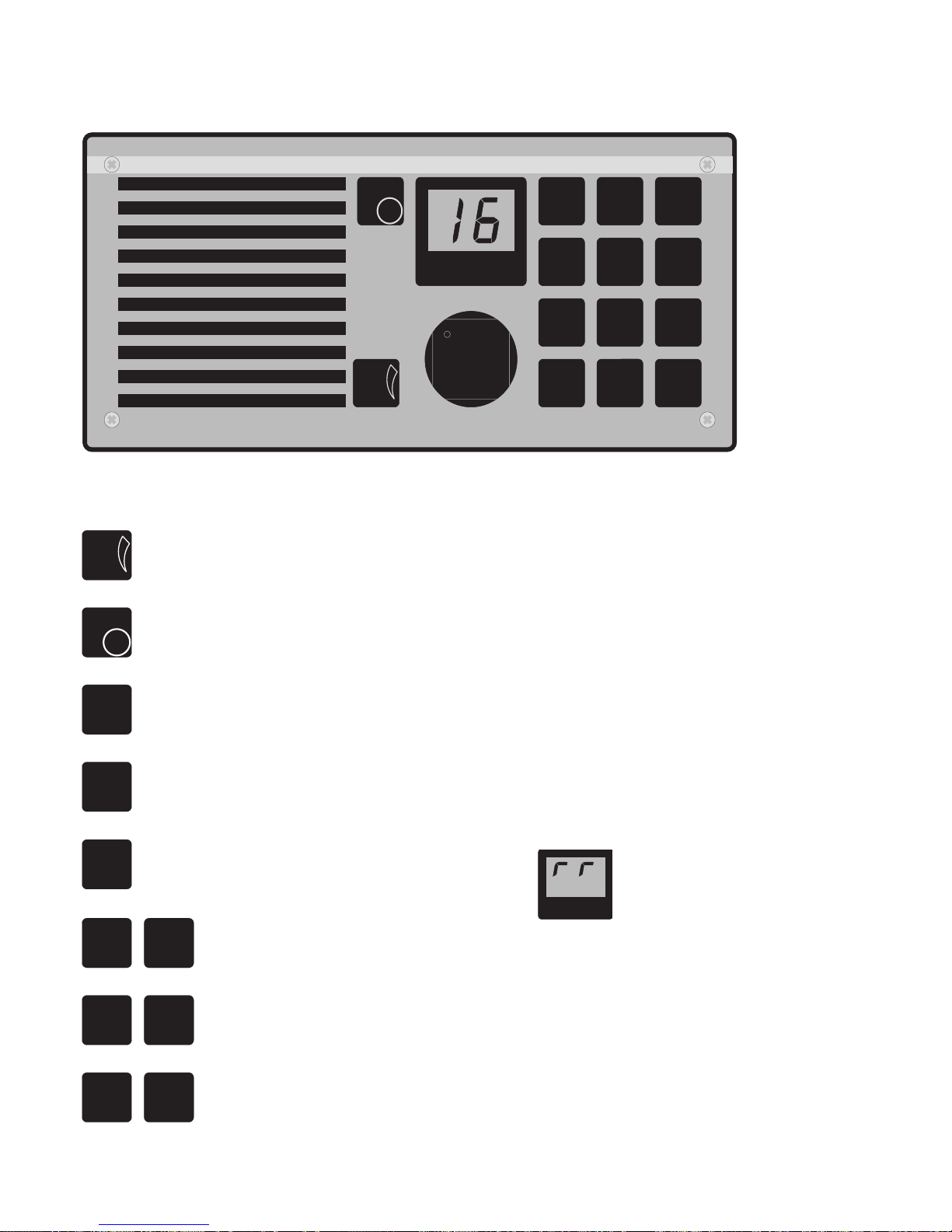
1.3. CONTROLS
SELCALL
OFF
VOL
SQ
1
4
2
5
8
DIM
7
P
0
SHIFT
16
1W
9
6
3
1W Tx
T / R
U.S.
DELETE
SCANSCAN
ADD
SCAN
SCAN
TIME
D.W.
US
VOL
OFF
Indication of ON/OFF/VOL turn-style knob operation.
SQ
Squelch sensitivity control knob with turn-style operation.
16
Quick selection of the call and distress channel 16.
SCAN
1
Digits from 1 to 0
SHIFT
Activates the functions marked in orange on the keyboard.
Whenever the keyboard is in “shift-mode” it will be
indicated by “cornerbars” in the display
1W Tx US
SHIFT
SCAN
1
Selects scanning programme.
SHIFT
SCAN
2
ADD
Adds a channel to the scanning table.
SHIFT
SCAN
3
DELETE
Deletes a channel from the scanning table.
9403
Page 1-4
1 INTRODUCTION RT2048
SHIFT
SCAN
5
TIME
Selects the scan time from 1 to 99 seconds.
The time chosen is the listening time on one of the secondary channels receiving
a signal.
SHIFT
D.W.
6
Selects the dual watch facility.
SHIFT
1W
9
Selects 1W reduced power output.
SHIFT
U.S.
8
Selects the VHF channels used in the USA.
SHIFT
DIM
7
The intensity of the LED-indicators can be controlled in four steps.
The keyboard illumination is switched on and off.
SHIFT
SELCALL
4
T / R
Tests the selcall decoder and resets the selcall decoder after a call.
SHIFT
P
0
Selects the standard private channels.
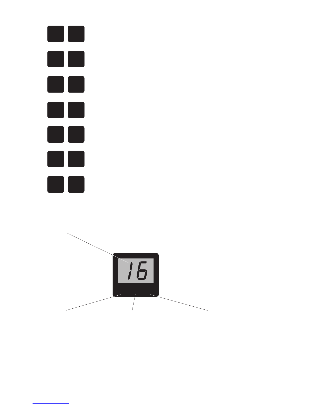
READ-OUT
Channel Read-Out All international maritime channels are shown by the two digits,
Reduced Power
In harbour areas or in the close
Where two stations are close
Transmitting
is depressed, and the transmitter
US-Channels
In the USA a number of the
Whenever the handset switch
output power level has reached
an appropriate level, the "TX"
will appear.
reduced from 25W to 1W
transmissions should be with
vicinity of another vessel,
When the display shows 1W,
reduced power.
the transmitter output power is
together, this reduction can
improve communication quality.
international duplex channels
are used as simplex channels.
Ships sailing in American waters
must therefore be able to select
these channels as simplex channels.
The appearance of "US" on the
display indicates that this mode of
operation is in use.
2
9655
Selection of a standard private channel will be indicated with a P-.
when the channel has been keyed in.
1W Tx US
9403
Page 1-5

1 INTRODUCTION RT2048
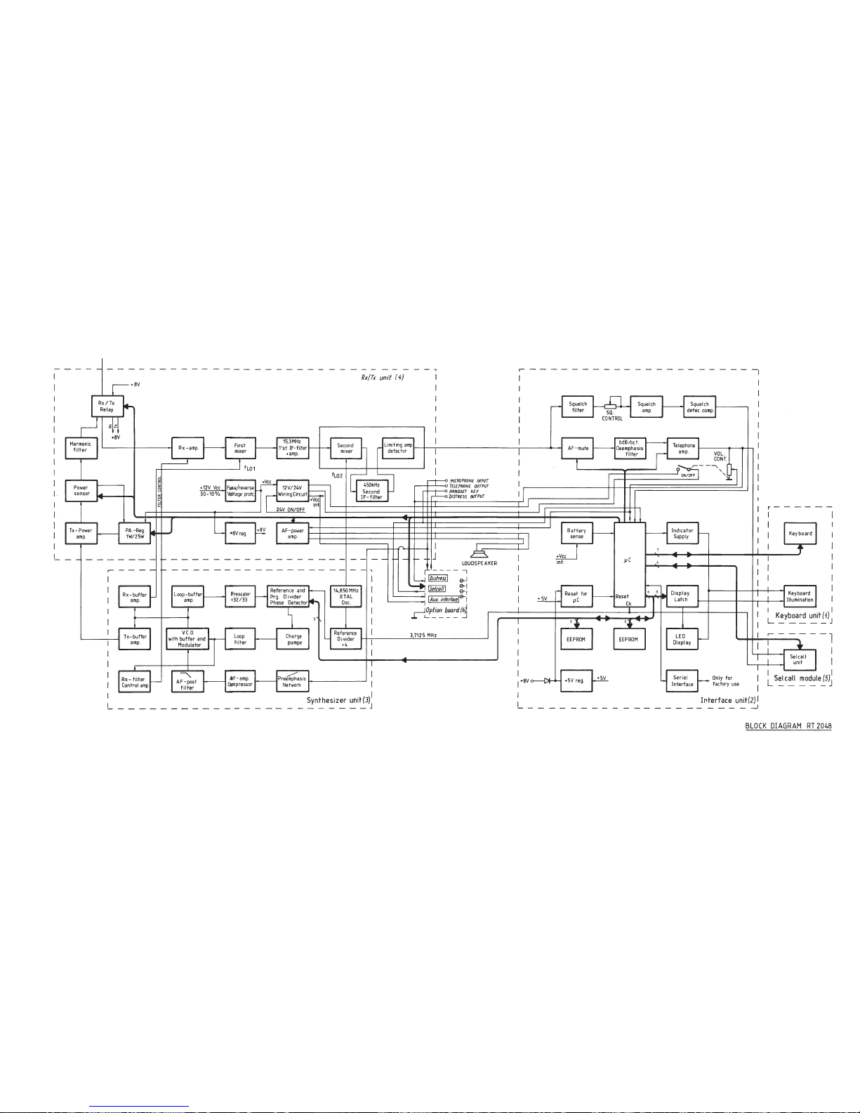
1.4. PRINCIPLE OF OPERATION
FREQUENCY GENERATION
All the internal frequencies are referenced to a crystal oscillator, running on 14.85 MHz.
The 14.85 MHz is divided by 4 in the REFERENCE DIVIDER, to generate a 3.7125 MHz signal, which is the input
to the PLL-reference divider and clock-signal for the microcomputer.
The local oscillator signal for the first mixer in the receiver and the transmit signal are generated in a phase-locked
loop (PLL). To generate the needed frequencies, which are specified as follows:
139.1 MHZ < fLO1 < 148.45 MHz; 154.5 MHz < fTX NORMAL < 159.15 MHz
159.0 MHz < fTX SPECIAL << 163.75 MHz
a bandshift is performed in the VCO.
The loop reference frequency - and so the resolution - is 12.5 kHz, derived by dividing the reference divider output
with 297.
The VCO output frequency is divided down to 12.5 kHz after the dual-modulus principle with a PRESCALER dividing
with 32/33.
The phase detector output controls the CHARGE PUMPE feeding the loop filter integrator.
If there is a difference in phase/frequency between the inputs to the phase detector. An error current from the charge
pumpe will be integrated in the loop filter, producing the needed voltage for the VCO.
RECEIVER
The antenna signal is fed to the RX AMPLIFIER through the RX/TX relay.
The bandpass filters around the RX amplifier are tuned by means of capacitor diodes, which are controlled by a DCvoltage derived from the VCO control voltage in the PLL.
The received signal is converted to the first intermediate frequency on 15.3 MHz in the FIRST MIXER, using the VCO
signal from the RX BUFFER AMPLIFIER as local oscillator signal.
The signal is filtered and amplified before down-conversion to 450 kHz in the SECOND MIXER. The crystal oscillator
signal is used as local oscillator signal.
After filtering in the SECOND IF FILTER, the signal is amplified and detected.
The AF signal is passed through a mute switch before undergoing appropriate amplification and filtering to get the
right frequency response.
Besides, the detected output is filtered in the SQUELCH FILTER before it is amplified, detected, and compared with
a reference level to get a logical level for the microcomputer, which controls the mute circuit.
The telephone amplifier and the AF power amplifier produce the wanted output levels for the earpiece and the
loudspeaker.
TRANSMITTER
The signal from the microphone is passed through a PRE-EMPHASIS network before appropriate amplification and
compression in the AF AMPLIFIER COMPRESSOR.
This signal is filtered before it is fed to the VCO, where the modulation of the transmitter signal takes place.
As the VCO oscillates direct on the transmitting frequency in TX-mode, the signal only has to be amplified. This is
done in the TX BUFFER AMPLIFIER and the TX POWER AMPLIFIER.
The power supply for the TX power amplifier is regulated by a feed-back loop via the POWER SENSE circuit to
maintain constant output power level. Switching between full and reduced output power level is made by means of
the PA-REGULATOR.
To reduce the level of harmonic components in the output signal it is passed through a HARMONIC FILTER before
it is led to the antenna via the RX-TX-RELAY.
MICROCOMPUTER
The microcomputer on the interface unit is taking care of various functions, among these the user interface, which
means reading of the keyboard and readout to the LED-display via the DISPLAY-LATCHES.
Moreover the computer calculates the appropriate division figures for the PLL, controls the transmitter power level,
the AF mute circuits, and reads and writes to the EEPROM’s.
When a selcall unit is installed, the microcomputer also controls the selcall switch capacitor filter.
The serial interface is only for factory production use.
9403
Page 1-6
1 INTRODUCTION RT2048
Page 1-7
9403
BLOCK DIAGRAM


2. INSTALLATION
Before installation of a SAILOR VHF RT2048 the following points must be observed:
1. Which facilities have to be enabled?
Selcall, private channels, US-mode, dual watch, scanning facilities, etc. The procedure how to enable the
facilities is described in the manual: INSTRUCTIONS FOR IDENTITY AND SERVICE PROGRAMMING OF
SAILOR VHF RT2048.
This manual will only be delivered to dealers and general agents, where it must be at the disposal of trained
service people in the service workshop.
2. In what way the VHF RT2048 has to be installed?
In the section MOUNTING POSSIBILITIES, the installation of VHF RT2048 is described either as an
independent unit or in combination with the other elements of the Compact 2000 programme.
3. Handset.
Installation of handset, see the section HANDSET.
4. External loudspeaker.
An external loudspeaker 4-8 ohm/6W can be connected to the power connector J1, pin 1 and 6, see the
section POWER CONNECTOR + EXT. LOUDSPEAKER.
5. Special options:
Remote alarm for selcall, AF to information decoder, AUX I and AUX II information, etc. are available, see
the section SPECIAL OPTIONS
9346
Page 2-1
RT2048

2 INSTALLATION RT2048
2.1. MOUNTING POSSIBILITIES
The VHF RT2048 cabinet is designed in a module called a mini 1/4 box. For this module we can supply a wide variety
of installation brackets etc. which will be described below. We have made a drawing including dimensions and
drilling plan for each type and we kindly ask you to look at the drawing for the type in question.
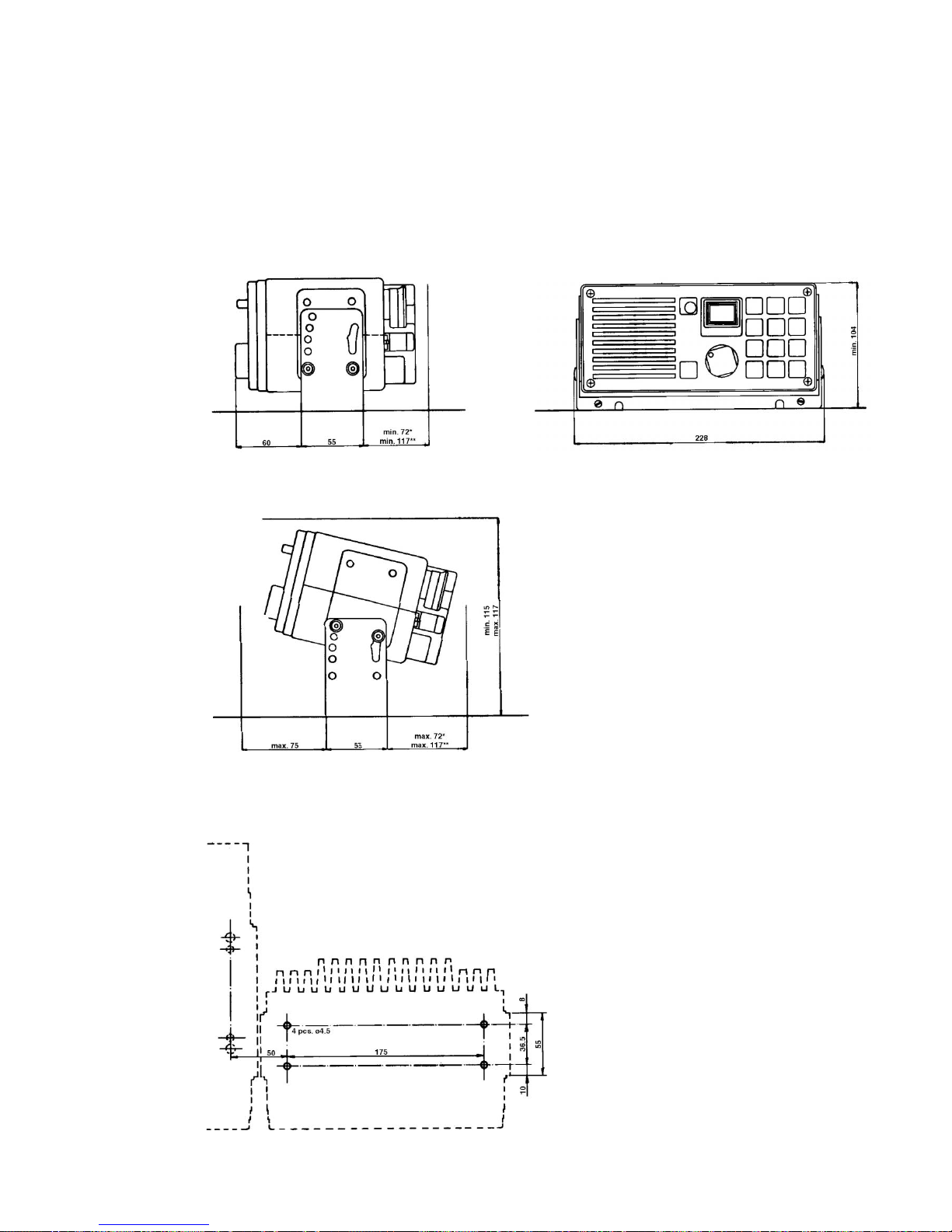
H2077 MULTI-PURPOSE MOUNTING BRACKET
This mounting bracket is as standard delivered together with RT2048. It permits a wide variety of installation
possibilities such as tabletop, bulkhead or deckhead. It is easy to remove the set by unscrewing the two buttons
of H2077.
H2077
25572 25571
Weight:
Mounting kit H2077: 0.4 kg
VHF RT2048: 3.2 kg
25668
9346
Page 2-2
182
52max. 65
*max. 60
**max. 96 252
139
25572
290
o
2 INSTALLATION RT2048
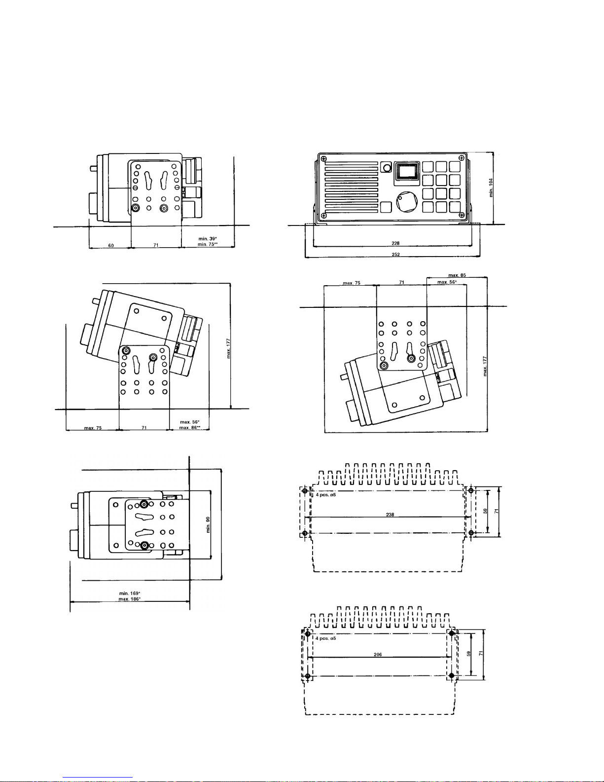
H2067 MOUNTING BRACKET FOR TABLETOP, BULKEHAD OR DECKHEAD MOUNTING FOR MINI 1/4 BOX
This mounting bracket is used when RT2048 is to be mounted next to other SAILOR units in the Compact 2000
programme mounted in H2055 mounting brackets. For example when installing the RT2048 next to the scrambler
CRY2001 it is possible to tilt both units in the same angle.
H2067
25574 25573
25575
Weight:
Mounting kit H2067: 0.5 kg
VHF RT2048: 3.2 kg
25659A
9346
Page 2-3
2 INSTALLATION RT2048
9346
Page 2-4
H2057 ANGLE HINGES FOR TABLETOP, BULKHEAD OR DECKHEAD MOUNTING FOR MINI 1/4 BOX
H2057 is designed for stationary installation. It offers a lot of mounting possibilities using the different holes in the
angle hinges when tilting the VHF.
H2057
25534 25530
25531A 25531
25669
25533
* Dimensions when using a right-angled VHF plug.
** Dimensions when using a standard VHF plug.
Weight: Mounting kit H2057: 0.4 kg
VHF RT2048: 3.2 kg
25670
9346
Page 2-5
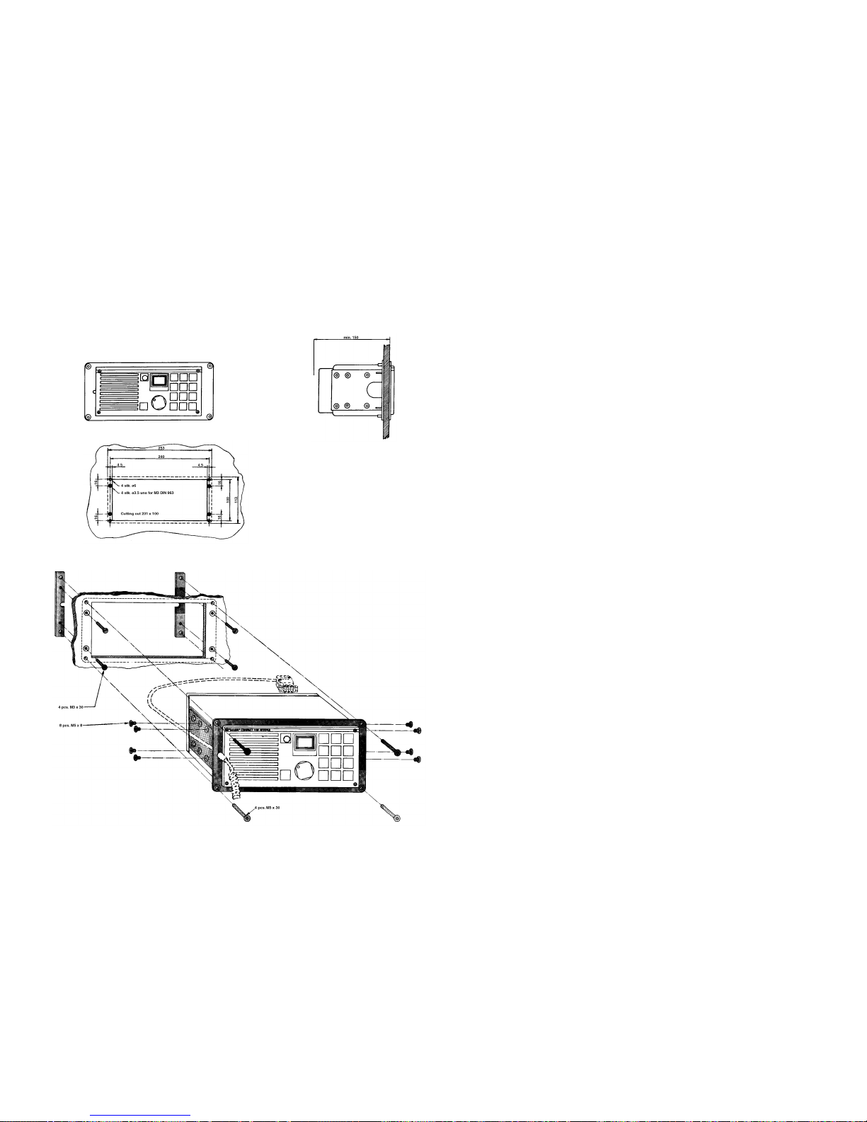
H2063 CONSOLE MOUNTING KIT FOR 1/4 BOX
This mounting kit is used for console flush mounting of 1/4 box and mini 1/4 box.
Free distance must be kept to allow free air circulation, ambient temperature max. 40
o
C.
H2063
25663
Weight:
Mounting kit H2063: 1.0 kg
VHF RT2048: 3.2 kg
24703
25657
2 INSTALLATION RT2048
2 INSTALLATION RT2048
2.2. HANDSET
The handset can be placed anywhere near the VHF set. The cable is five-cored and connected to the rear
of the VHF through a 9-pole Sub-D connector.
Installation of the cable, see the drawings of the mounting brackets. The cable grommet must be placed
in the most convenient groove in the mounting bracket.
If more than one handset is needed, please see the section SPECIAL INSTALLATION WITH 2 OR 3
MICROTELEPHONES.
2.3. MICROTELEPHONE CONNECTOR
Pin No. 1 Telephone
Pin No. 2 GND
Pin No. 3 GND
Pin No. 4 Mic
Pin No. 5 Key
Pin No. 6 Spare
Pin No. 7 Distress CRY*
Pin No. 8 “Serial input”
25666 Pin No. 9 +13V internal
* only active when option board pcb is installed.
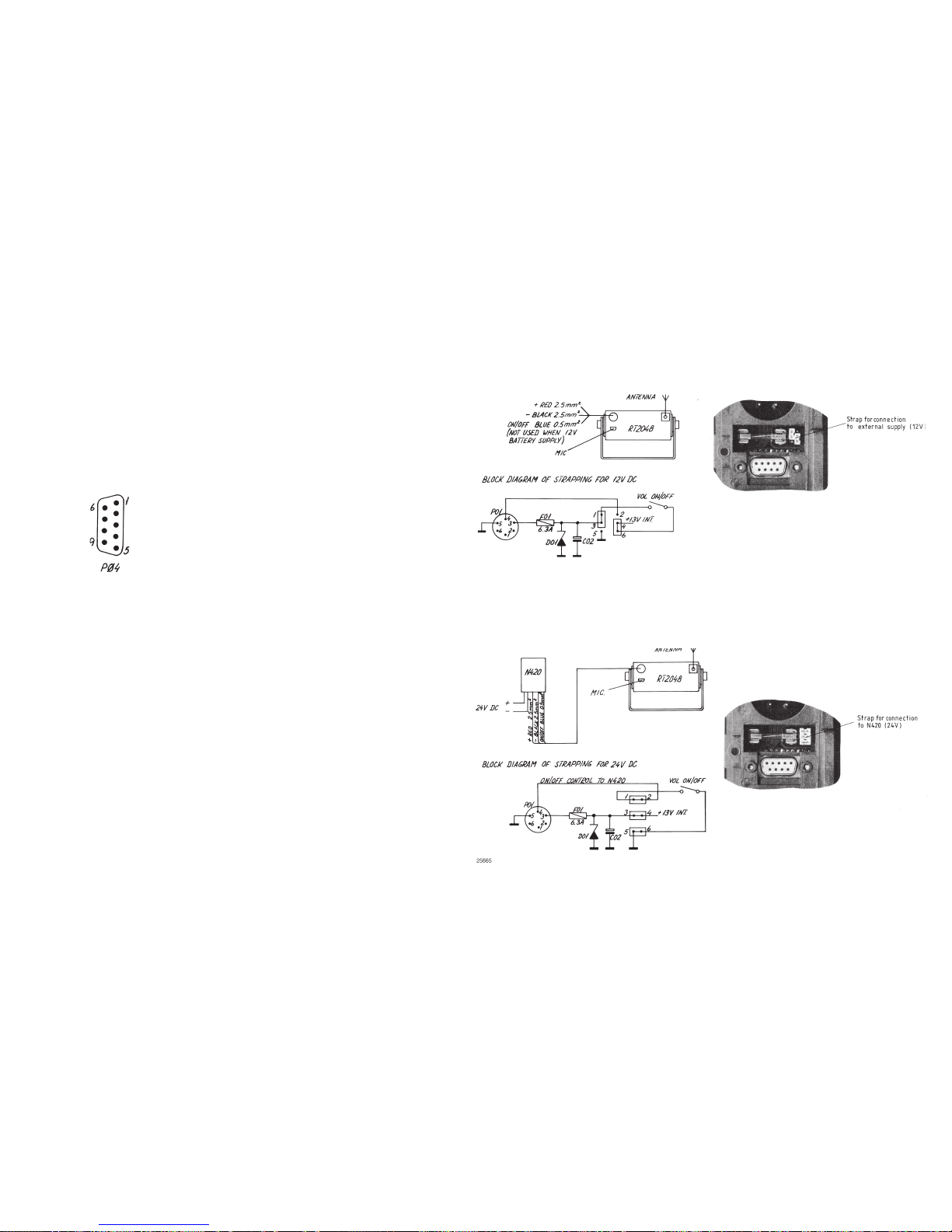
2.4. POWER SUPPLY
The standard power supply for RT2048 is 12V DC. For 24V DC supply an external power supply N420
(a 24V DC to 13.2V DC serial regulator) can be used.
For 110V AC, 127V AC, 220V AC, or 237V AC operation an external power supply N163S must be used
together with N420.
Page 2-6
9346
25664
25665

2 INSTALLATION RT2048
2.5. POWER CONNECTOR + EXT. LOUDSPEAKER
VIEW FROM MOUNTING SIDE
Pin No. 1 Ext. loudspeaker
Pin No. 2 Ext. mute*
Pin No. 3 +12V power supply
Pin No. 4 on/off for 24V supply
Pin No. 5 -12V power supply
Pin No. 6 Ext. loudspeaker
24914
* only active when option board pcb is installed.
If necessary a 4-8 ohm/6W external loudspeaker can be connected to pin No. 1 and pin No. 6 in the power connector
J01 (observe that there is DC voltage on both wires).
External loudspeakers SAILOR H2054 and H2074 are available.
2.6. ANTENNAS
All common 50 ohm antennas, which cover the used frequency range with a reasonable standing wave ratio,
maximum 1.5, are available.
The antenna is connected to the set by means of a 50 ohm coaxial cable with low loss, e.g. RG213U. At the cable
end a PL259 plug is mounted.
The antenna must be placed as high and clear as possible. The horizontal distance to metal parts must be at least
one metre.
Thrane & Thrane has an antenna of the necessary specifications available. The mentioned antenna is characterized by small external dimensions. For further particulars see special brochure VHF AERIALS.
2.7. SPECIAL OPTIONS
With a small modification in RT2048 the following options are available:
1. K-switch function (used on river boats in Germany). Can be enabled by means
of the identity programming. US-button is changed to K-switch.
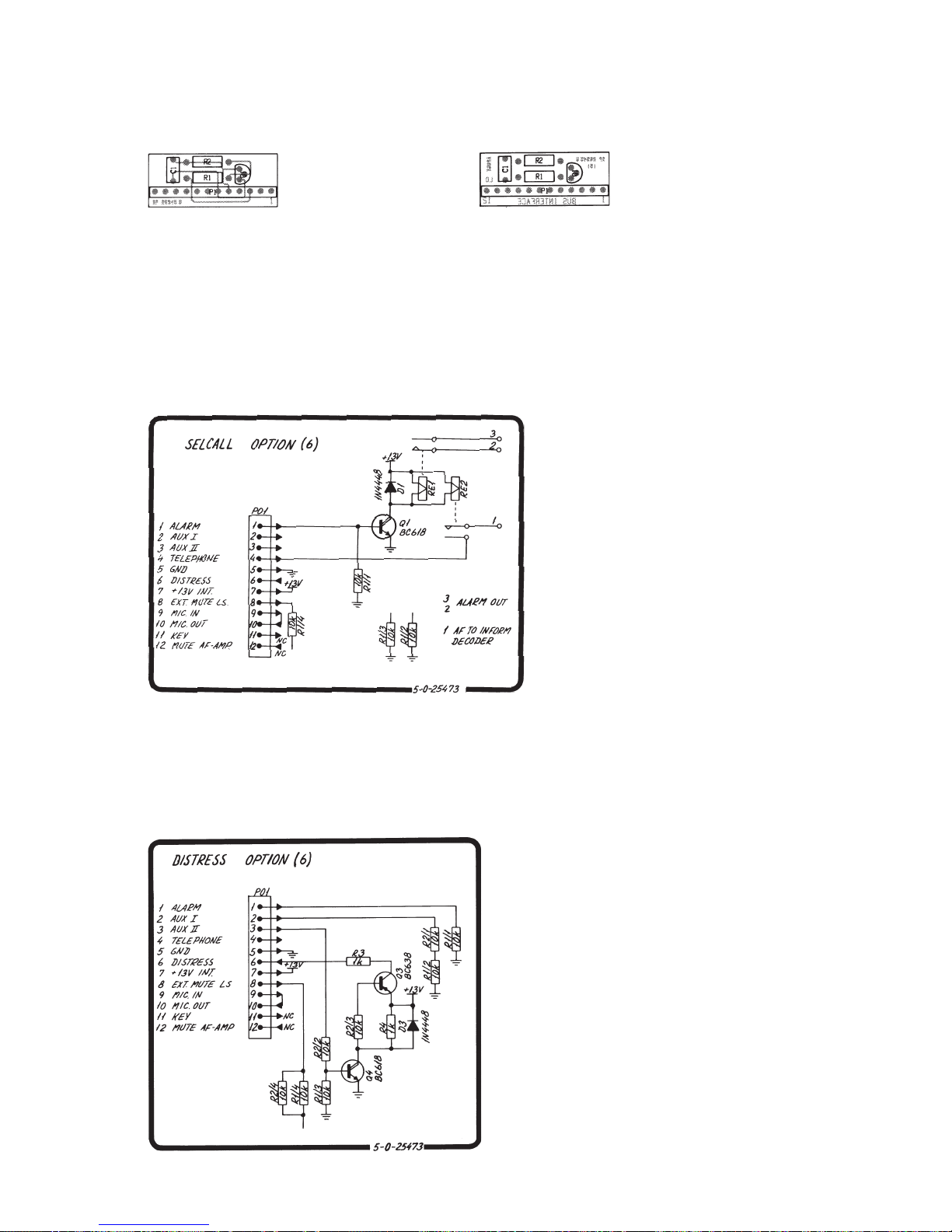
2. With DISTRESS OPTION installed
Part no. 625661
a. Distress output to CRY2001/2002.
3. With SELCALL OPTION installed
Part no. 625660
a. SELCALL RELAY, when the selcall has accepted a CQ or an individual call signal, the selcall
relay will turn on and short circuit two wires, which can be used for remote alarm.
Max. contact load: 100V AC/24V DC - 2A.
b. AF TO INFORMATION DECODER, the circuit giving AF signals to the information decoder
is turned on when the set has accepted a CQ or an individual call signal. The circuit is turned
on/off by the microprocessor.
0820
Page 2-7
2 INSTALLATION RT2048
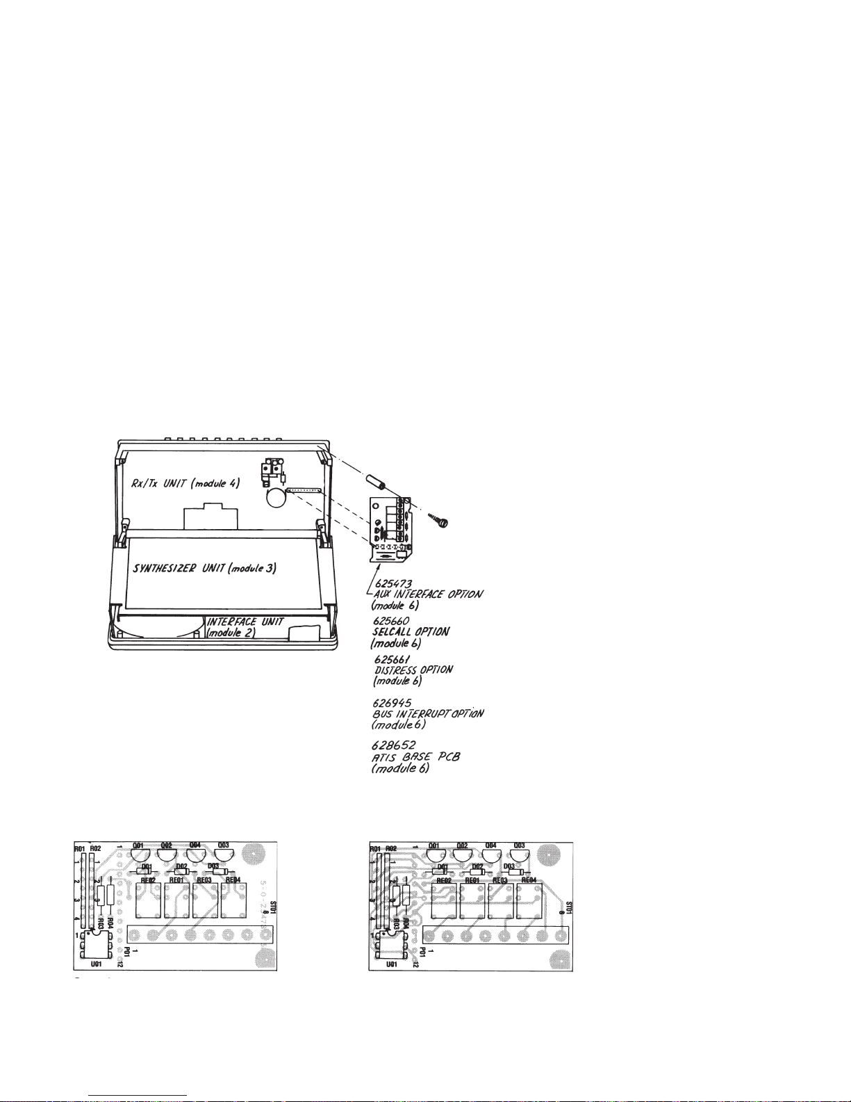
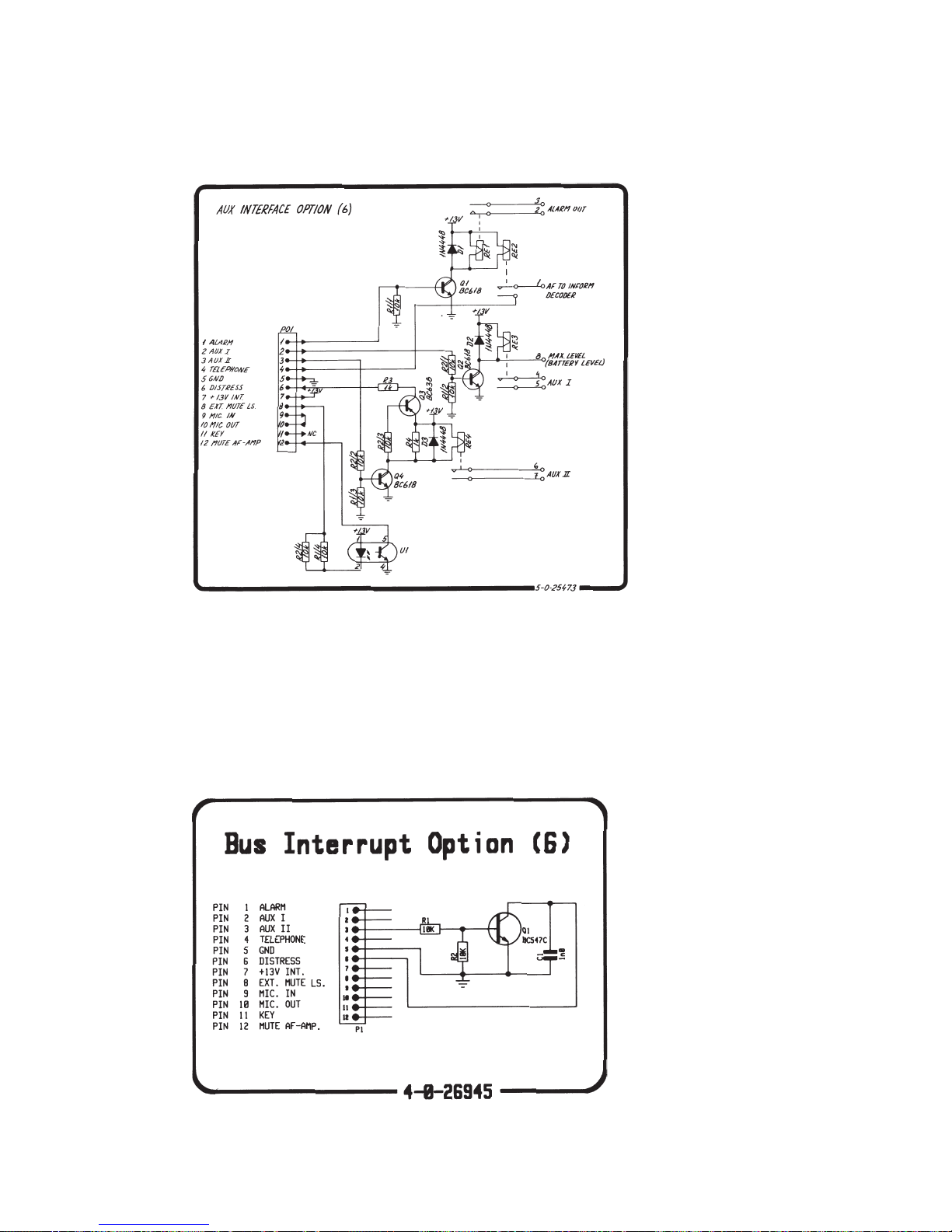
4. With AUX INTERFACE OPTION installed
Part no. 625473
(AUX1, AUX2 and MUTE functions) (Distress and Selcall functions are also mounted).
a. AUX2, when information on certain channels is wanted, i.e. controlling a watch keeping
receiver, the AUX2 information can be used, a relay is controlled from the microprocessor.
Max. contact load: 100V AC/24V DC - 2A.
b. AUX1, when function code in Prom 1 is enabled, AUX1 is free programmable on all
international channels (“0” or “1”).
Standard programming on international channels is “0”.
Max. contact load: 100V AC/24V DC-2A.
c. MUTE, makes it possible to mute AF power amplifier from external equipment.
Activated by a make function between pin 5 and pin 8 in P1 on option board.
5. With BUS INTERRUPT OPTION installed
Part no. 626945
This module is used for interface to VHF DSC RM2042.
6. With ATIS OPTION installed
Part no. 728665
The module 628652 is used for interface to ATIS module 626707, which is mounted on this PCB.
For circuit description and programming of ATIS option please refer to Appendix A - ATIS OPTION
25662A
COMPONENT LOCATION FOR SPECIAL OPTIONS MODULES
VALID FOR 625661 / 625660 / 625473
Seen from component side Seen from component side
with upper side tracks. with lower side tracks.
PCB rev. 25473
0820
Page 2-8
2 INSTALLATION RT2048
9346
Page 2-9
COMPONENT LOCATION FOR 626945
Seen from soldering side Seen from soldering side
with soldering side tracks. with component side tracks.
PCB rev. 26945
DIAGRAMMES FOR SPECIAL OPTIONS
625660
625661
2 INSTALLATION RT2048
Page 2-10
9346
626945
625473
2 INSTALLATION RT2048
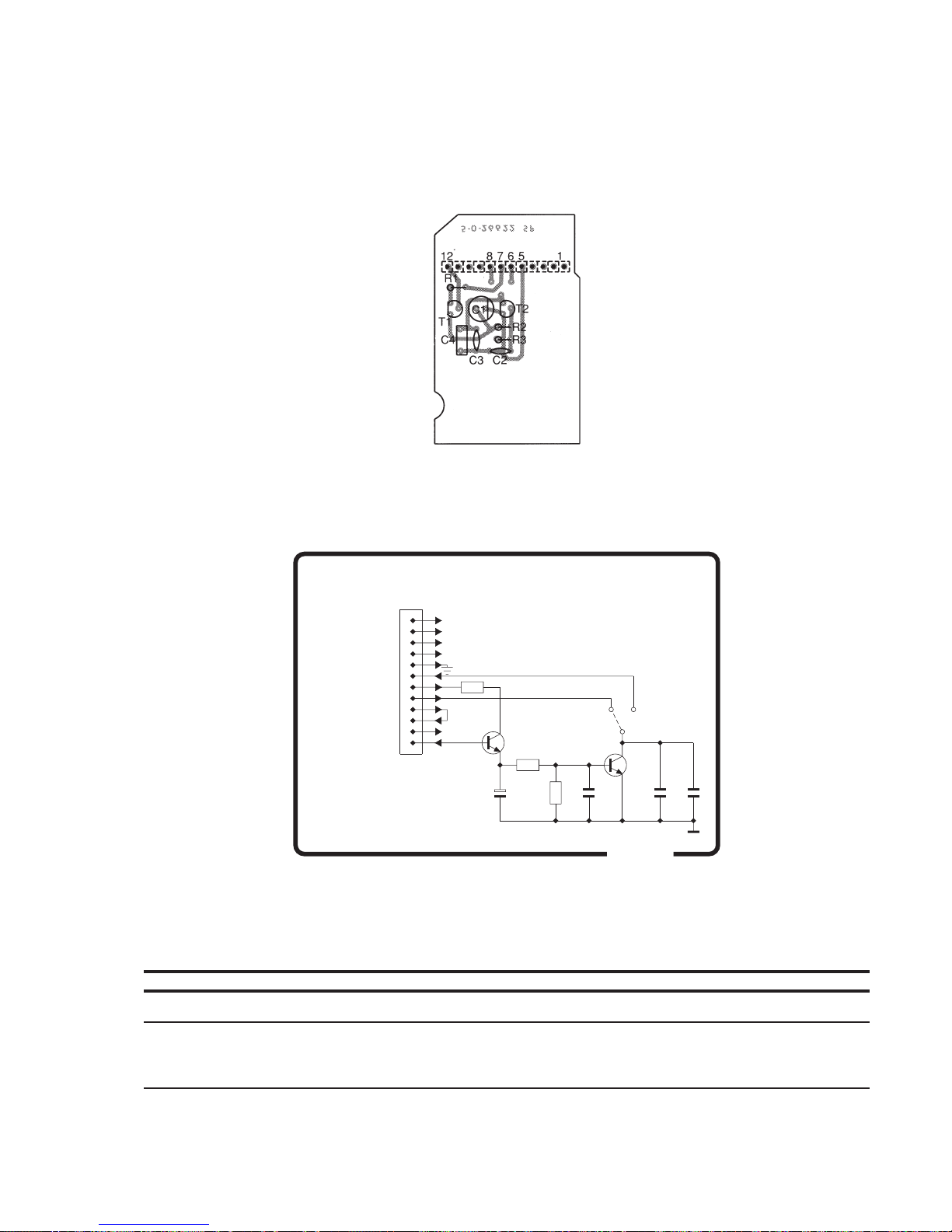
DELAYED KEY OPTION
To make a repeater station on a duplex channel, you need two pcs. of RT2048, one for receiving on Lo band, one
for transmitting on Hi band. To get this function, the function code has to be reprogrammed for the specified channel
in both sets. The modulation signal is taken on the earpiece from the receiver unit and led to the microphone input
of the transmitter unit. No attenuation required. The key for the transmitter unit is taken from the special option
board, Delay Key Option, to get the transmitter unit keyed approx. 10 seconds after last received signal.
Seen from component side with upper side tracks.
626622
4-0-26622
12 MUTE AF-AMP
11 KEY
10 MIC. OUT
9 MIC. IN
8 EXT. MUTE LS.
7 +13V INT.
6 DISTRESS
5 GND
4 TELEPHONE
3 AUX II
2 AUX I
1 ALARM
1
2
3
4
5
6
7
8
9
10
11
12
470
150
1M
R2
R1
R3C1C2
10uF
470p
T1
BC548
T2
BC548
1nC3C4
100n
P01
DELAYED KEY OPTION (6)
NC
Page 2-10a
9520
2 INSTALLATION RT2048
DELAYED KEY OPTION MODULE (6) RT2048 ECI A/S 5-0-26622/2-0-25473A 626622
POSITION DESCRIPTION MANUFACTOR TYPE PART NO.
C1-6 CAPACITOR ELECTROLYTIC 10uF 20% 25VDC ELNA RBL-25-V-100-M-V2Z-T58 14.661
C2-6 CAPACITOR CERAMIC 470pF 10% 500VDC KCK RT-HM60 SK YB 471 K 16.095
C3-6 CAPACITOR CERAMIC 1nF 10% 50VDC CL2 KCK RT-SK-HE50 SJYB 102 K 16.160
C4-6 CAPACITOR MKT 0.1uF 10% 63VDC PHILIPS 2222 370 78104 11.136
J1-6 PLUG 1/10" SIL 12 POLES EURO DIP SL 12 O Z 78.328
R1-6 RESISTOR MF 470 OHM 5% 0.33W PHILIPS 2322 187 7347 02.464
R2-6 RESISTOR MF 150k OHM 5% 0.33W PHILIPS 2322 187 73154 02.524
R3-6 RESISTOR MF 1M OHM 5% 0.33W PHILIPS 2322 187 73105 02.544
T1-6 TRANSISTOR AF BC548 NPN TO-92 PHILIPS BC548 (-A/-B/-C) 28.070
T2-6 TRANSISTOR AF BC548 NPN TO-92 PHILIPS BC548 (-A/-B/-C) 28.070
2 INSTALLATION RT2048
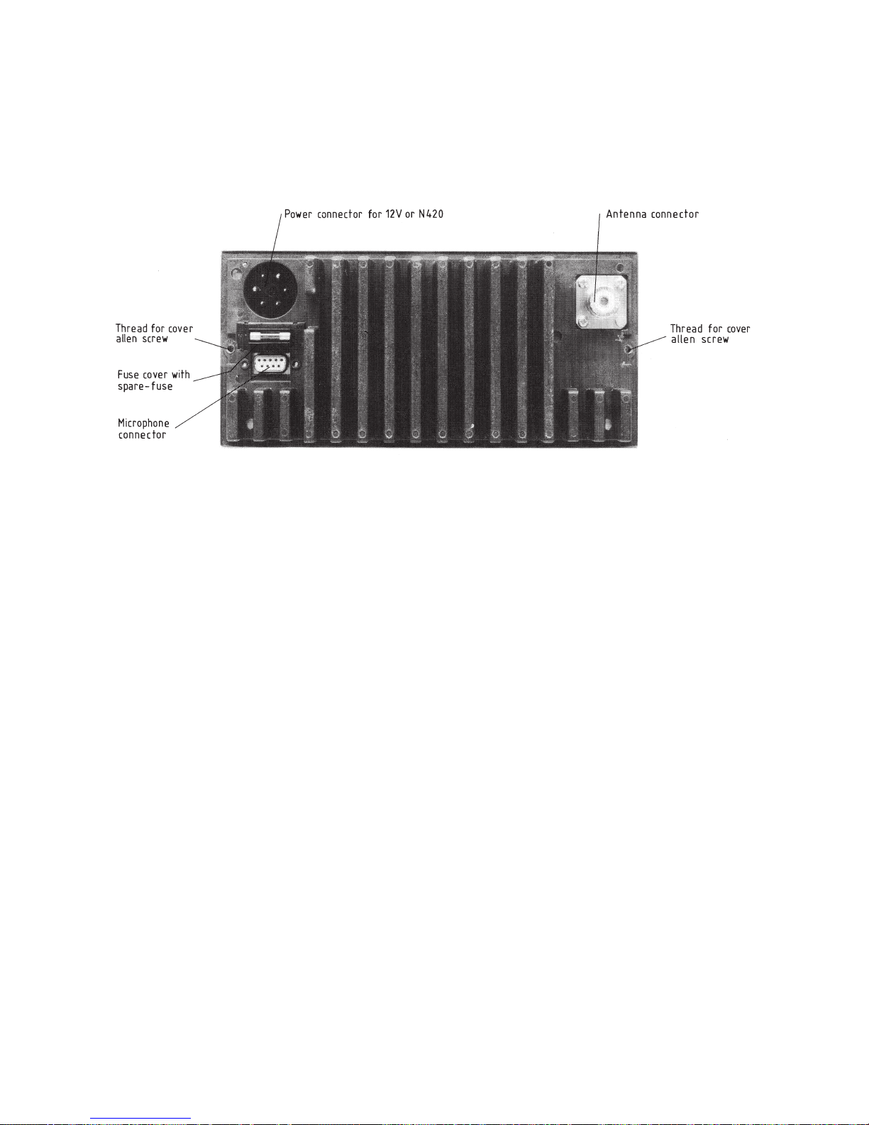
2.8. REAR VIEW OF VHF RT2048
25567
9350
Page 2-11

2 INSTALLATION RT2048
Page 2-12
0549
US-MODE
(A.-CHANNELS)
INT'L MODE
(INT.-CHANNELS)
01 156.050 156.050 160.650
02 156.100 160.700
03 156.150 160.750
04 156.200 160.800
05 156.250 156.250 160.850
06 156.300 156.300
07 156.350 156.350 160.950
08 156.400 156.400
09 156.450 156.450
10 156.500 156.500
11 156.550 156.550
12 156.600 156.600
13 156.650 156.650
14 156.700 156.700
15 156.750 156.750
16 156.800 156.800
17 156.850 156.850
18 156.900 156.900 161.500
19 156.950 156.950 161.550
20 157.000 161.600
21 157.050 157.050 161.650
22 157.100 157.100 161.700
23 157.150 157.150 161.750
24 157.200 161.800
25 157.250 161.850
26 157.300 161.900
27 157.350 161.950
28 157.400 162.000
60 156.025 160.625
61 156.075 160.675
62 156.125 160.725
63 156.175 156.175 160.775
64 156.225 160.825
65 156.275 156.275 160.875
66 156.325 156.325 160.925
67 156.375 156.375
68 156.425 156.425
69 156.475 156.475
70 156.525 156.525
71 156.575 156.575
72 156.625 156.625
73 156.675 156.675
74 156.725 156.725
75 156.775 156.775
76 156.825 156.825
77 156.875 156.875
78 156.925 156.925 161.525
79 156.975 156.975 161.575
80 157.025 157.025 161.625
81 157.075 157.075 161.675
82 157.125 157.125 161.725
83 157.175 157.175 161.775
84 157.225 161.825
85 157.275 161.875
86 157.325 161.925
87 157.375 157.375
88 157.425 157.425 157.425
WX1 Inhibit 162.550
WX2 Inhibit 162.400
WX3 Inhibit 162.475
WX4 Inhibit 161.650
RECEIVING FREQUENCY (MHz)TRANSMITTING
FREQUENCY
(MHz)
CHANNEL
2.9. STANDARD FREQUENCY TABLE


3. SERVICE
3.1. MAINTENANCE
PREVENTIVE MAINTENANCE
If SAILOR RT2048 has been installed in a proper way the maintenance can be reduced to an overhaul at each visit
of the service staff. Then inspect the set, the antenna, cables, and plugs for mechanical damages, salt deposits,
corrosion, and any foreign material. Owing to its traditional structure, the SAILOR RT2048 has a long lifetime, but
it must always be carefully checked at intervals not exceeding 12 months - dependent on the conditions under which
the set is working. The set must be brought to the service workshop to be tested.
Along with each set a TEST-SHEET is delivered in which all the measurements, made in the test department of
the factory, are listed. If the control measurings made in the service workshop should not show the same values
as those listed in the test-sheet, the set must be adjusted as specified in the ADJUSTMENT PROCEDURE.
3.2. ALIGNMENT INSTRUCTIONS
INTRODUCTION
The measuring values indicated in paragraph 2 of CIRCUIT DESCRIPTION AND SCHEMATIC DIAGRAMS are
typical values and as indicated it will be necessary to use instruments in absolute conformity with the below list:
3.3. PROPOSAL FOR NECESSARY MEASURING INSTRUMENTS
VHF Signal Generator type TF2015 MARCONI
FM Modulation Meter type TF2303 MARCONI
Distortion Analyzer type TF2337A MARCONI
AF Voltmeter type VT-121 TRIO
Tone Generator type PM5107 PHILIPS
Electronic Multimeter type PM2505 PHILIPS
RF Directional Wattmeter Model 43 BIRD SOW
Load with 30 dB Attenuator type 8321 BIRD
Frequency Counter:
Frequency range >175 Mhz
Sensitivity <100 mv
Impedance >1 Mohm and 50 ohm
Accuracy <1 - 10
-6
We can also recommend one of the new communication test sets introduced by several instruments manufacturers.
From S. P. Radio this high quality product will be tested and adjusted by means of a CMT communication tester
from Rohde and Schwarz.
RT2048
Page 3-1
 Loading...