

Page 1
.:;,,
1;
-
\
7-7
A/S S. P. RADIO . AALBORG . DENMARK
Page 2
INSTRUCTION BOOK FOR
RECEIVER R1119/R1120
VALID FROM
S,N,
255239
Page 3
CONTENTS:
GENERAL DESCRIPTION ....................................... 2
TECHNICAL DATA ............................................ 3
CONTROLS .................................................. 5
DIRECTION FOR USE .........................................
7
PRINCIPLE OF OPERATION .................................... 9
AERIAL TUNE PROCEDURE .....................................
SERVICE: ..................................................
1. MAINTENANCE ............................................
2.
NECESSARY TEST EQUIPMENT ...............................
3.
TROUBLE-SHOOTING .......................................
14
16
16
17
21
4. PERFORMANCE CHECK ...................................... 24
5. ADJUSTMENT PROCEDURE ................................... 33
6. NECESSARY ADJUSTMENT AFTER REPAIR ......................
7.
FUNCTION CHECK ......................................... 45
41
PIN CONFIGURATIONS ........................................ 50
ADJUSTMENT LOCATIONS ...................................... 52
CIRCUIT DESCRIPTION AND SCHEMATIC DIAGRAMS
PARTS LISTS
MAIN SCHEMATIC DIAGRAM
Page 4
GENERAL DESCRIPTION
INTRODUCTION
SAILOR
A2, A2H, Al & Fl signals in the.frequency range
RI120
is a main receiver intended for reception of A3, A3H, A3A, A3J,
10
kHz to 30 MHz.
SAILOR RI120 uses a digital synthesizer for frequency generation, and thus
can be set to any frequency in the above mentioned frequency range. The digital synthesizer is controlled from a key board or the built-in continuous tu-
ning wheel, the frequency selected is displayed on a six segment liquid cry-
stal display (LCD). The frequency stability is controlled from one 10 MHz TCXO.
SAILOR RI120 is prepared for use in conjunction with telex and faximile equipment.
SAILOR RI120 is provided with higher order tunable RF filters to ensure good
duplex performance. 0
SAILOR RI120 has automatical RF filter selection.
SAILOR R1120 fits into SAILOR lg'l rack system.
SAILOR RI120 can be supplied with a selfcontaining cabinet H1225, and an
AC/DC power supply N1405 with automatic change-over from AC to DC.
Page 5
TECHNICAL DATA
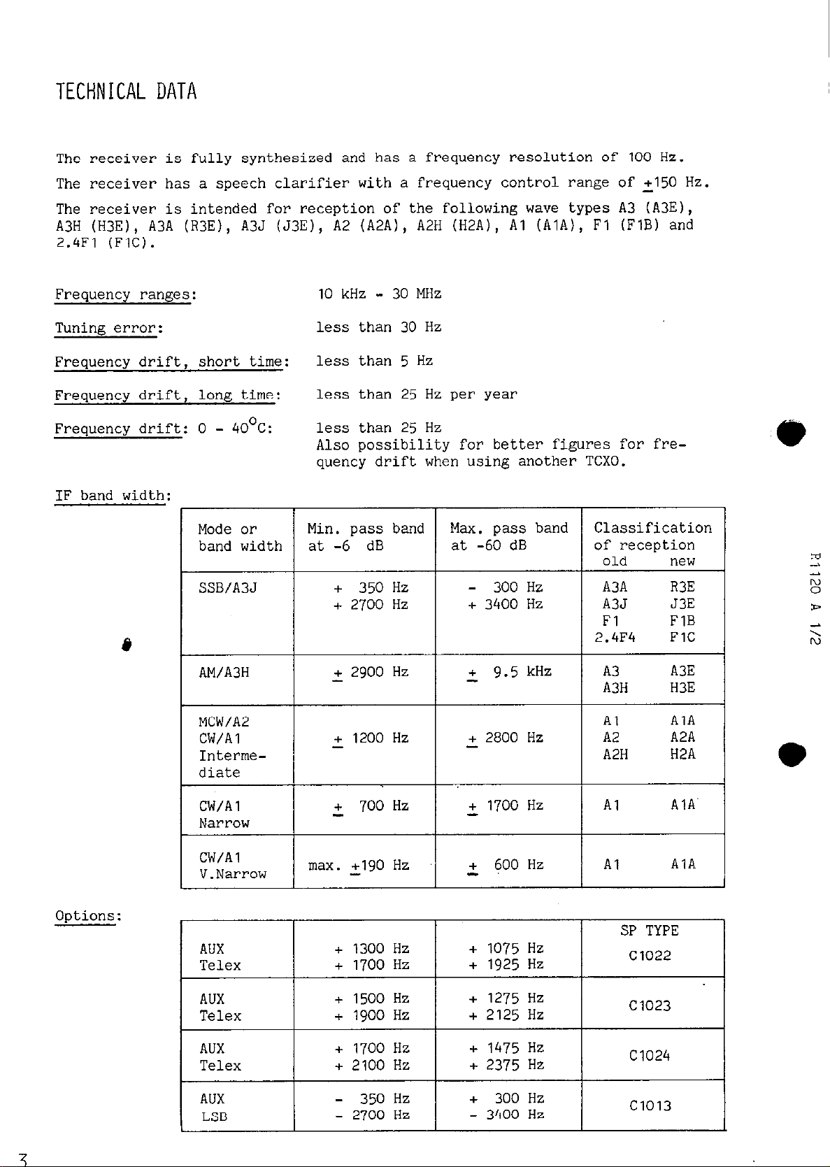
The receiver is fully synthesized and has a frequency resolution of 100 Hz.
The receiver has a speech clarifier with a frequency control range of 2150 Hz.
The receiver is intended for reception of the following wave types A3 (A3E),
A3H (H3E), A3A (R3E), A3J (J3E), A2 (A2A), A2H (H2A), Al (AlA), Fl (FlB) and
2.4Fl (FIG).
-
30
Frequency ranges:
10
kHz
MHz
Tuning error:
Frequency drift, short time:
Frequency drift, long time:
Frequency drift: 0 - 40°C:
IF band width:
/
1 SSB/A3J
less than 30 Hz
less than 5 Hz
less than 25 Hz per year
less than 25 Hz
Also possibility for better figures for frequency drift when using another TCXO.
T
Max. pass band
at -60 dB
Classification
of reception
old new
+
350
I
Hz
- 300
+
3400
Hz
Hz
A3A R3E
A3J J3E
Fl FlB
2.4F4 FlC
2 9.5 kHz
A3 A3E
A3H
Al AlA
+
2800
Hz
A2
A2H H2A
H3E
A2A
Options:
CW/Al
V.Narrow
AUX
Telex
AUX
Telex
AUX
Telex
AUX
LSB
max. cl90 Hz
+
1300
Hz
+
1700
Hz
+
1500
Hz +
+ 1900 Hz
+
1700
Hz +
+
2100
Hz +
-
350
Hz +
-
2700
Hz -
2
1700
Hz
2 600 Hz
+
1075
Hz
+
1925
Hz
1275
Hz
+
2125
Hz
1475
Hz
2375
Hz
300
Hz
3400
Hz
Al AlA
Al
AlA
SP TYPE
Cl022
Cl023
Cl024
Cl013
Page 6
TECHNICAL DATA cont.:
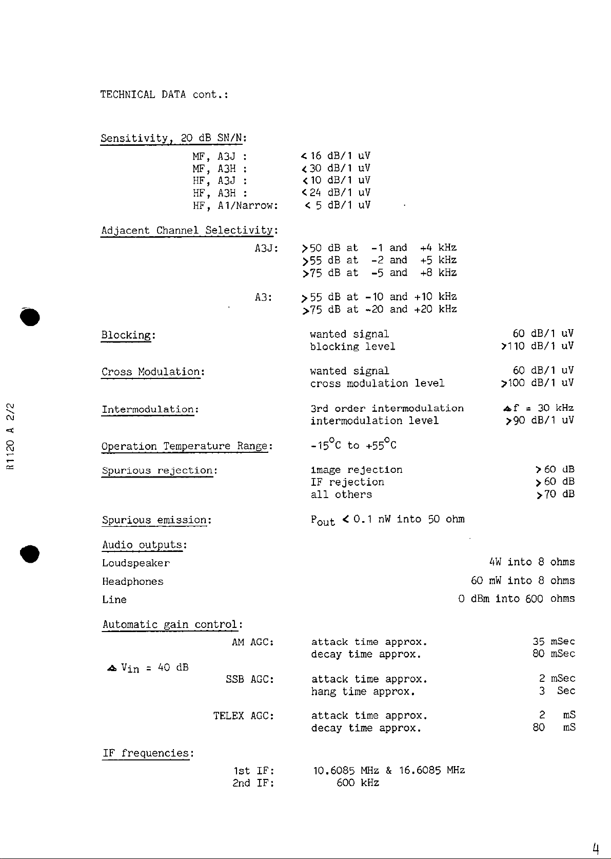
Sensitivity, 20 dB SN/N:
MF, A3J :
MF, A3H : 430 dB/l uV
HF, A3J :
HF, A3H :
HF, Al/Narrow: < 5 dB/l uV
Adjacent Channel Selectivity:
A3J:
A3:
Blocking:
Cross Modulation:
Intermodulation:
Operation Temperature Range:
cl6
dB/l uV
<IO
dB/l uV
<24 dB/l uV
>50
dB at
)55
dB at
>75 dB at
>55
dB at
>75
dB at -20 and +20 kHz
-1
and +4 kHz
-2
and +5 kHz
-5
and +B kHz
-10
and
+I0
kHz
wanted signal 60 dB/l uV
blocking level
wanted signal
cross modulation level
3rd order intermodulation
intermodulation level
-15Oc to +55Oc
7110
dB/l uV
60 dB/l uV
>I00 dB/l uV
raf = 30 kHz
,$JO dB/l uV
l
Spurious rejection:
Spurious emission:
image rejection
IF rejection
all others
Pout < 0.1 nW into 50 ohm
>60
dB
>60
dB
>70 dB
Audio outputs:
Loudspeaker 4W into 8 ohms
Headphones
60
mW into 8 ohms
Line 0 dBm into 600 ohms
Automatic gain control:
AM AGC: attack time approx.
decay time approx.
35
80
mSec
mSec
Q Vin q 40 dB
SSB AGC:
TELEX AK: attack time approx.
attack time approx.
hang time approx.
decay time approx.
2
mSec
3 Set
2
80
mS
mS
IF frequencies:
1st
IF:
2nd IF:
10.6085
600
MHz & 16.6085 MHz
kHz
4
Page 7
'CONTROLS R1120
ED
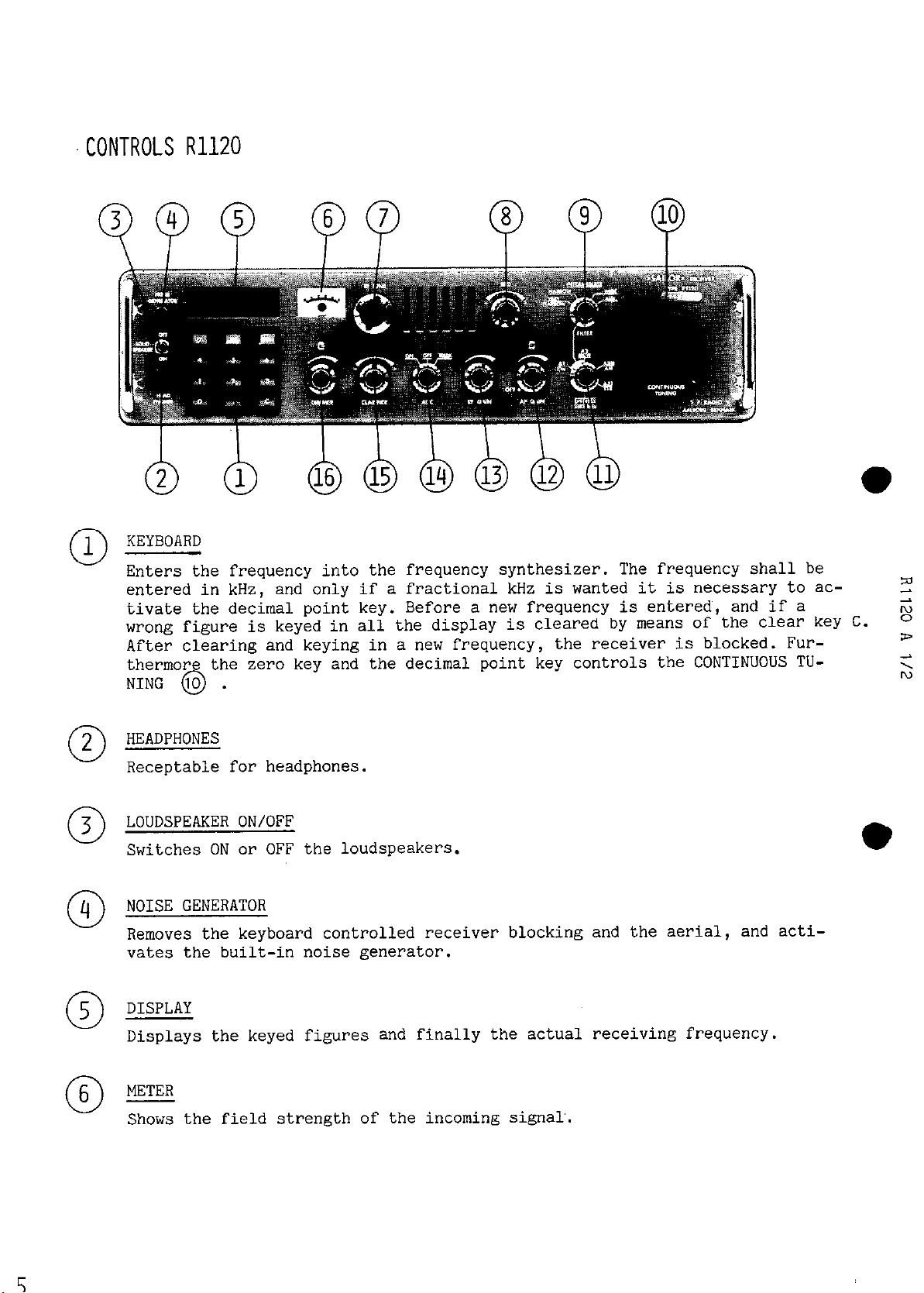
KEYBOARD
1
0
Enters the frequency into the frequency synthesizer. The frequency shall be
entered in kHz, and only if a fractional kHz is wanted it is necessary to ac-
tivate the decimal point key. Before a new frequency is entered~, and if a
wrong figure is keyed in all the display is cleared by means of the Clear key C.
After clearing and keying in a new frequency, the receiver is blocked. Fur-
thermor the zero key and the decimal point key controls the CONTINUOUS TUNING
10
&
.
,a
g
2
2
0
3
0
m
5
0
6-
0
HEADPHONES
Receptable for headphones.
LOUDSPEAKER ON/OFF
Switches ON or OFF the loudspeakers.
NOISE GENERATOR
Removes the keyboard controlled receiver blocking and the aerial, and acti-
vates the built-in noise generator.
DISPLAY
Displays the keyed figures and finally the actual receiving frequency.
METER
Shows the field strength of the incoming signal.
l
Page 8
CONTROLS cont.:
7
0
8
0
9
0
l 10
0
RF TUNE
Tunes the band filter to the chosen frequency.
BFO
Adjusts the beat note in Al mode.
FILTER
Chooses the wanted bandwidth in Al- and A2 mode, and disables the BFO in the
AUX. position.
CONTINUOUS TUNING
Is activated by pressing the decimal point key on the KEYBOARD @ , and
tunes over the full frequency range
sing the zero key on the KEYBOARD
MODE SWITCH
Switches between reception of fixed
A3H - (A3H and A3), A2 (A2 and A2H) and Al signals.
The tuning wheel can be disabled by pres-
0
.
2182
kHz (Distress), A3J - (A3J and A3A),
12
0
0
0 l3
14
0
15
0
16
0
AF GAIN
Controls the AF output and turns the mains on/off.
RF GAIN
Controls the overall RF amplification in the receiver.
AGC
Changes between slow (ON) and fast (TELEX) release time for the SSB AGC system
or switches OFF the AGC.
CLARIFIER
Provides incremental tuning over a +I50 Hz frequency range.
DIMMER
Controls the light intensity from the DISPLAY and the METER.
6
Page 9
DIRECTIONS FOR USE
INITIAL SETrINGS
Turn on the receiver on the AF GAIN
and turn the AF GAIN
(12)
to approx. middle position.
(12)
or on the power supply N1400 or
N1401
Turn the CLARIFIER (15) to the center position, the RF GAIN (13) fully clock-
wise and the AGC SWITCH (14) to position ON. Choose the wanted mode of recep-
tion on the MODE SWITCH
(II).
(For further description of mode filter - and AGC
selection, please examine the paragraphs below).
FREQUENCY CONTROL
The frequency is controlled from the KEYBOARD
wheel. The wanted frequency must be entered into the KEYBOARD
(I)
and the CONTINUOUS TUNING (10)
(1)
in kHz and
is then displayed on the liquid crystal DISPLAY (5). The decimal point is only
to be used when a fractional kHz is wanted. After- entering a frequency the receiver is blocked and the CONTINUOUS TUNING
(10)
wheel is disabled.
After keying in a frequency you must press the NOISE GENERATOR (4) and adjust
RF TUNE (7) for maximum reading on the METER (6). For frequencies below 150 kHz
chosen there is no tuning to be done on the RF TUNE (7), just press NOISE GENERATOR (4) to unblock the receiver.
Now the wanted frequency is selected and the receiver front end is tuned. The
CLARIFIER (15) controls the frequency between the
For searching over a frequency range the CONTINUOUS TUNING
vated by pressing the decimal point key on the KEYBOARD
frequency is found the CONTINUOUS TUNING
(10)
100
Hz steps selectable.
(10)
wheel is acti-
(1).
When the desired
wheel can be disabled by pres-
sing the zero key on the KEYBOARD (I).
The CONTINUOUS TUNING (IO) wheel is able to tune the receiver over the full
frequency range
10
kHz to 30 MHz. It is necessary to follow the frequency tuning wheel with the front end tuning on the RF TUNE (7). Each time you pass a
band limit by means of the CONTINUOUS TUNING
limits: 150 kHz, 530 kHz, 1.6 MHz, 4 MHz, 7 MHz,
(10)
the receiver blocks. (Band-
14 MHz and 30 MHz). To unblock
the receiver again you must press the NOISE GENERATOR (4) and adjust the RF-
TUNE (7) for maximum METER (6) reading.
l
,P
s
>
s
0
DISTRESS
With the controls set as described under INITIAL SETTINGS above just turn the
MODE SWITCH
(II)
to DISTRESS
(2182
kHz.1 position.
Now the receiver is ready
for reception on the distress frequency, mode selection (AM) and front end tu-
ning is automatically done in the receiver.
SSB TELEPHONY
For normal telephony purpose turn the MODE SWITCH
(II)
to A3J (SSB) position.
Now SSB reception of normal upper sideband is established.
For SSB telephony purpose the preferable AGC
(14)
position is ON.
Page 10
DIRECTIONS FOR USE cont.:
It is possible by means of the RF GAIN
(13)
to control the attack level for the
AGC system in such a way that signals below a certain level not attacks the AGC
system.
In noisy environments it can be advantageous to switch OFF the AGC (14) and con-
trol the gain by the RF GAIN
(13)
to avoid that noise impulses activates the AGC
circuit.
Another possibility for gain regulation under strong repetitive noise impulses
is to switch the AGC
(14)
to the TELEX position and turn the RF GAIN
(13)
fully
clockwise.
The AGC system now regulates the amplification down immediately and thus prevents the noise impulse to be heard in the loudspeaker. When the noise impulse
disappears again the amplification increases rapidly. This fast AGC system sup-
presses effectively noise impulses,
but for SSB purpose it furthermore introduces some distortion because of the missing hang time in this position. For that
reason it is only advantageous to use the TELEX AGC system when your environ-
ments is so noisy that the ON pos. is unusable.
GENERAL BROADCASTING
With the controls set as described under INITIAL SETTINGS above, turn the MODE
SWITCH
ency or search by means of the CONTINUOUS TUNING
(11)
to A3H (AM) position. Now you are ready to key in a wanted frequ-
(IO)
as described under FRE-
QUENCY CONTROL.
TELEX IN SSB MODE
For telex reception the receiver is operating as described under SSB TELEPHONY.
Because of the nature of the telex signal (it contains no envelope modulation)
is the most advantageous AGC
(14)
choice the TELEX one. The extremely good
noise performance of this AGC is fully utilized because no distortion can be
introduced.
Special attention must be paid to the frequency selected. The telex service fre-
quencies listed by the authorities are assigned frequency. For that reason you
must set the frequency either 1700 Hz or 1500 Hz below the assigned frequency,
depending upon the telex equipment used.
TELEX IN AUX, MODE IF TELEX FILTER IS FISTED
As in the TELEX IN SSB MODE except that the MODE SWITCH
(11)
is set to posi-
tion Al (CW) and the FILTER SWITCH (9) to position AUX.
WDLILATED TELEGRAPH
With the controls set as described under INITIAL SETTINGS above, turn the MODE
SWITCH
The AGC system now chosen is the SSB one,
(11)
to position A2 (MCW) and the FILTER SWITCH (9) to INTERMEDIATE.
and you must set the AGC (14) to the
most suitable position (ON or TELEX) after the present noise conditions.
TELEGRAPHY
With the controls set as described under INITIAL SETTINGS above, turn the MODE
SWITCH
(11)
to Al (CW) position and turn the FILTER SWITCH (9) to suitable band-
width. Now the receiver is ready for telegraphy reception and the BFO (8) is ope-
rational and can be tuned to a desirable beat note. For the same reasons as de-
scribed in the telex paragraph the most advantageous AGC
(14)
choice is the ON one.
e
Page 11

PRINCIPLE OF OPERATION
9
Jj
RECEIVER Rllzo
The SAILOR
with
10.6085
The signal from the aerial is led through the BAND FILTER UNIT to the
FIRST MIXER, where the aerial signal is mixed with the fLO1 signal having frequency resolution of 1 kHz, and thus giving a 1st IF frequency
range from
R1120
or
10.6081
is a fully synthesized double superhetereodyne receiver
16.6085
MHz 1st IF and 600 kHz 2nd IF.
MHz to
10.6090
MHz or
16.6081
MHz to
16.6090
MHz.
Page 12
PRINCIPLE OF OPERATION cont.:
The signal is then led through a double monolitic crystal filter to the
SECOND MIXER, where the signal is mixed with the fL02 signal having con-
tinuous tuning in the frequency range from
or
16.00795
600
kHz.
The
16.6085
13.9999
The protluced 2nd IF signal is led through one of the five filters available on the IF FILTER UNIT. The switching takes place electronically by
means of the MODE and/or the FILTER SWITCH.
The signal is then passed on to the IF2 AMPLIFIER and DETECTOR. The IF
amplifier consists of 3 AGC controlled amplifier stages. The detector for
both AM and SSB reception is an envelope detector, and in the SSB and CW
mode the carrier is reinjected in such a way that the incoming signal is
converted to an A3H signal.
MHz to
MHz
MHz and
16.00915
1st
IF is selected in the frequency range
10.6085
MHz, and thus giving a 2nd IF frequency of
MHz in the range
10.00795
14.0000
MHz to
MHz to 29.9999 MHz.
10.00915
0.0100
MHz to
MHz
l
The reinjected carrier in SSB mode is 600 kHz
ference oscillator, and in CW mode the carrier signal from the beat fre-
quency oscillator BFO is used.
kHz and 601.8 kHz.
The AGC DETECTOR AND AMPLIFIER consists of the AM AGC system and the hang
AGC system.
The audio frequency signal is fed from the detector to the AF FILTER AND
AMPLIFIER, consisting of an audio filter,
power amplifier, which delivers signal to the fixed AF output (0 dBm),
the headphones and the speakers.
FREQUENCY GENERATION
The necessary frequencies are generated by two frequency synthesizers according to the phase locked principle.
Local oscillator signal fLO, to FIRST MIXER is generated in the phase locked
loop
Local oscillator signal fL02 to SECOND MIXER is generated in the phase locked
loop 2 and has a resolution of
steps by means of the CLARIFIER.
1
and has a resolution of 1 kHz.
This frequency can be varied between 599.5
100
Hz, and continuous tuning over the 100 Hz
derived
a preamplifier and an output
from the 10 MHz re-
LOOP
The voltage controlled oscillator (VCO) generates the necessary local oscilla-
tor signal to FIRST MIXER in twelve 2 MHz bands selected by the BAND CONTROL
UNIT. Inside each 2 MHz band the VCO frequency fLOl
trolled voltage derived from the PHASE DETECTOR and filtered out in the LOOP 1
FILTER.
1
is controlled by a DC con-
10
Page 13
PRINCIPLE OF OPERATION cont.:
The PHASE DETECTOR compares two signals, a variable frequency f
rence f+equency fR,. The reference frequency fR1 is the IO MHz
divided down to 1 kHz.
The variable frequency fV1 is generated from the VCO frequency fL0, in the
following way:
In the LOOP 1 MIXER the counter frequency fTl is produced as the difference between the VCO frequency fLO, and the frequency fHARM which is a multiple of 2
MHz derived from the 10 MHz TCXO.
= fLOl - fHARM = fLOl
fT1
For each 2 MHz band a new fLOl and fHARM is selected by the BAND CONTROL UNIT,
and it always results in a 2 MHz variation of the frequency fTl to PROGRAMMABLE
DIVIDER.
The frequency fT1 is divided down by a dividing figure NJ in the PROGRAMMABLE
DIVIDER to the variable frequency fV,.
fVl z fTl/Nl = 1 kHz
The working principle in a phase locked loop is as follows:
A frequency error between the variable frequency fV1 and the reference fre-
quency fRl will via the PHASE DETECTOR and the LOOP 1 FILTER cause a DC
control voltage controlling the VCO frequency and consequently the variable
frequency fV1 so that fV1 follows the reference frequency fR1 in frequency.
=
fR1
fVl
- (m x 2 MHz) q N1 x 1 kHz
q 1
kHz
The VCO frequency fL0, is now phase locked on a fixed frequency to the re-
ference frequency fRJ and has therefore the same accuracy as this.
Changing of the VCO frequency fLO1 by 1 kHz is carried out by changing the
dividing figure N1 in the PROGRAMMABLE DIVIDER by one.
fLol q fHARM + (N, X 1 kHz)
Principle of programming:
The PROGRAMMABLE DIVIDER contains a counter circuit counting down from a
start figure 2000 + PI and stops at the stop figure St. Each time the coun-
ter reaches the stop figure S,,
TOR, and the counter starts counting down again from the start figure 2000 +
PI. Division of fTl by N1 is now achieved.
fv, = fT,/N,;
a pulse (fV1) is fed to the PHASE DETEC-
N, = 2000 + P1 - S1
l
Page 14
PRINCIPLE OF OPERATION cont.:
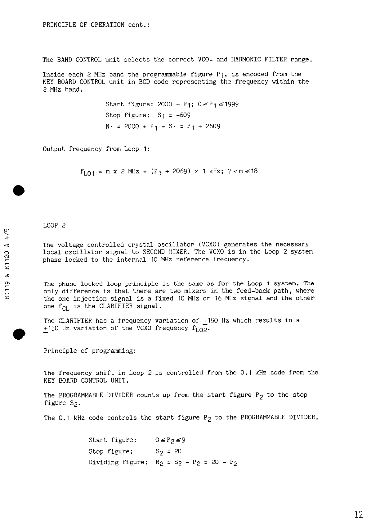
The BAND CONTROL unit selects the correct VCO- and HARMONIC FILTER range.
Inside each 2 MHz band the programmable figure PI, is encoded from the
KEY BOARD CONTROL unit in BCD code representing the frequency within the
2 MHz band.
l
Start figure: 2000 + Pi; 04P1
&I999
Stop figure: SI = -609
N, =
2000
+ Pl - S, q P1 + 2609
Output frequency from Loop
1:
fLOl = m x 2 MHz + (PI + 2069) x 1 kHz; 7rmd18
LOOP 2
The voltage controlled crystal oscillator (VCXO) generates the necessary
local oscillator signal to SECOND MIXER. The VCXO is in the Loop 2 system
phase locked to the internal
10
MHz reference frequency.
The phase locked loop principle is the same as for the Loop 1 system. The
only difference is that there are two mixers in the feed-back path, where
the one injection signal is a fixed
10
MHz 0~
16
MHz signal and the other
one fCL is the CLARIFIER signal.
The CLARIFIER has a frequency variation of
2150
Hz which results in a
2150 Hz variation of the VCXO frequency fLO2.
Principle of programming:
The frequency shift in Loop 2 is controlled from the
0.1
kHz code from the
KEY BOARD CONTROL UNIT.
The PROGRAMWBLE DIVIDER counts up from the start figure P2 to the stop
figure S2.
The
0.1
kHz code controls the start figure P2 to the PROGRAMMABLE DIVIDER.
Start figure: OhP2rz9
Stop figure: s2 q 20
Dividing figure:
N2 = S2
- P2 q 20 - P2
12
Page 15
PRINCIPLE OF OPERATION cont.:
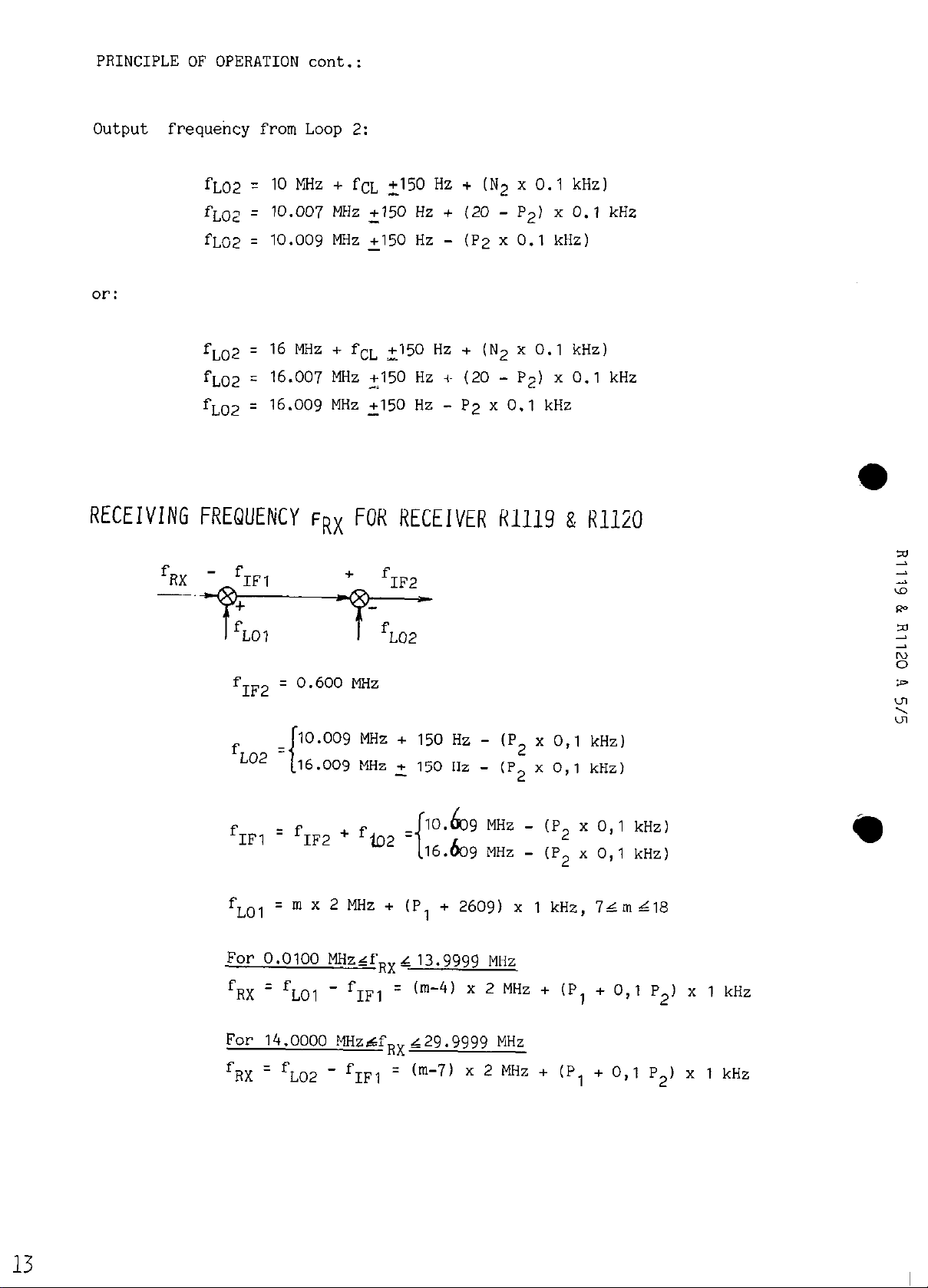
Output frequency from Loop 2:
fLO2 T:
fLO2 =
fLC2 =
10
MHz + fCL
10.007 MHz +I50
10.009
MHz
or:
fL02 =
fL02 :
fL02
RECE IVING FREQUENCY
fUX
- fIFl
16
MHz + fCL 2150 Hz + (N2 x 0.1 kHz)
16.007
q 16.009
MHz
MHz 2150 Hz - P2 x 0.1 kHz
FRX
+I50 Hz + (N2 x 0.1 kHz)
+150
-
+I50
Hz + (20 - P,) x
Hz - (P2 x 0.1 kHz)
Hz -I- (20 - P2) x 0.1 kHz
0.1
kHz
FOR RECEIVER R1119 & RlliO
+
fIF2
fLo2
f
IF2 = 0.600
10.009
fL02 =
fIF1
fLOl
For
16.009 MHz c 150
i
q
fIF2 + fio2 =
= m x 2 MHz + (P, + 2609) x 1 kHz,
0.0100
fFiX = fLOl - fIFl
MHz
MHz +
MHzLfRXL
= (m-4) x 2
150
Hz - (P;! x
Hz - (P2 x
lO.& 9 MHz - (P2 x
16.609
t
13.9999
MHz - (P, x
MHz
MHz + (P, + 0,l P2) x 1 kHz
For 14.0000 MHztfRXL29.9999 MHz
f
RX = fL02 - fIFl
=
(m-7)
x 2
MHz + (PI +
0,l
0,l
kHz)
kHz)
0,l
0,l
7Lmd18
0,l
kHz)
kHz)
P2) x 1 kHz
13
Page 16

AERIAL TUNE PROCEDURE
When the receiver has been installed the aerial trimmer for the
filter must be adjusted,
and for installation with short coax cables
it may be advantageous to adjust the aerial trimmer for the C.T. band
2182
kHz input
12 m.
1
1.6 -
4 MHz.
NOTE: The length of the coax cable is from the aerial input socket of the re-
ceiver to the connection box for the aerial.
Aerial trimmer C.T..
High
0.15-0.53
Low
0.15-0.53 MHz...
High
0.53-1.6 MHz...
MHz..
Low 0.53-1.6 Mhz....
Low f 0.15 MHz.....
High f 0.15 MHz....
Aerial trimmer
2182
kHz............
ADJUSTING PROCEDURE
1
. . Set mode switch to pos. 2182 kHz.
2.
Set AGC switch to pos. ON.
Turn RF GAIN fully clockwise.
3.
4.
Turn AF GAIN to suitable volume.
Adjust by means of an insulated trimming stick the aerial trimmer
5.
2182
kHz:
for max. METER reading or max. noise in the loudspeaker.
ADJUSTING PROCEDURE C.T. BAND (cable length
1.
Set mode switch to pos. AM.
Set AGC switch to pos. ON.
2.
3.
Turn RF GAIN fully clockwise.
Turn AF GAIN to suitable volume.
4.
12
m.):
2182
kHz
Page 17

AERIAL TUNE PROCEDURE cont.:
15
Key in a low frequency in the C.T. band e.g.
5.
1610
kHz by means of the
KEYBOARD.
Activate the NOISE GENERATOR and adjust RF TUNE for max. meter reading.
6.
Press the decimal point key on the KEYBOARD and search by means of the
7.
CONTINUOUS TUNING wheel for a weak station in the low end of the C.T.
band.
Adjust RF TUNE for max. METER reading.
8.
Adjust by means of an insulated trimming stick the aerial trimmer C.T.
9.
for max. METER reading.
10.
Repeat 8) and 9) until no essential improvement is achieved.
CHANGE OF INPUT IMPEDANCE FOR FREQUENCIES BELOW
1.6
MHz:
For installations with short coax cables and short aerials it may be advan-
tageous to shift from 50 ohms input impedance, pos. LOW to high input impe-
dance pos. HIGH.
To determine which pos. is the most advantageous, search for a weak station
near the band limits, note the METER readings.
Change for the other input
impedance and check if the METER readings have increased. Remember to adjust
RF TUNE.
Band limits: 150 kHz, 530 kHz and
1.6
MHz.
Page 18

SERVICE
1, MAINTENANCE
2, NECESSARY TEST EQUIPMENT
3, TROUBLE-SHOOTING
4, PERFORMANCE CHECK
5, ADJUSTMENT PROCEDURE
6, NECESSARY ADJUSTMENTS AFTER REPAIR
7, FUNCTION CHECK
8, MECHANICAL DISASSEMBLING T1127 ONLY
1, MAINTENANCE
1.1.
When the SAILOR SHORT WAVE SET type
tenance can, dependent on the environment and working hours,
formance check at the service workshop at intervals not
plete performance check list is enclosed in the PERFORMANCE CHECK section.
Also inspect the antennas, cables and plugs for mechanical defects, salt deposits,
corrosion and any foreign bodies.
Along with each set a TEST SWEET is delivered, in which
made at the factory are listed. If the performance check does not show the same
values as those on the TEST SHEET, the set must be adjusted as described under
ADJUSTMENT PROCEDURE.
Any repair of the set should be followed by a FUNCTION CHECK of the unit in
question.
1000
has been correctly installed, the main-
be
reduced to a per-
exceeding 5
some
of the measurings
years. A com-
16
Page 19

2, NECESSARY TEST EQUIPMENT
TX: T1127, T1127L
EXC:
51300, S1301
RX: R1119, R1120
N1400, N1401
PS:
OSCILLOSCOPE:
Bandwidth
Sensitivity
Input impedance
Triggering
E.g. PHILIPS type
PASSIVE PROBE:
Attenuation
Input resistance
Input capacitance
Compensation range
E.g. PHILIPS type
MULTIMETER:
Sensitivity DC (f.s.d.)
Input impedance
Accuracy (f.s.d.1
E.g. PHILIPS type
DC - 35 MHz
2 mV/cm
1
Mohm//30 pF
EXT-INT-ENVELOPE
PM3216
20
dB
(10X)
10
Mohm
15
PF
10 - 30
pF
PM8925
IV
10 Mohm
+?/O
-
PM2505
I 17
MULTIMETER:
Sensitivity DC (f.s.d.)
Input impedance
Accuracy (f.s.d.)
Current range
Voltage range
E.g. Unigor
Shunt
type
type
H.T.probe type
0.3V & 3A
30
k&m/V
+l%
100
A
500V & 2.5 kV
A43
GE4277
GE4196
Page 20

NECESSARY TEST EQUIPMENT cont.:
:X
-
xc
X
X
IX
X
X
X
‘S
-
TONE GENERATOR:
Frequency range
output voltage
Output impedance
E.g. PHILIPS type
AF VOLTMETER:
Sensitivity (f.s.d.)
Input impedance
Accuracy (f.s.d.1
Frequency range
E.g. PHILIPS type
FREQUENCY COUNTER:
Frequency range
Resolution
Accuracy
Sensitivity
Input impedance
Single period range
Resolution
E.g. PHILIPS type
200 - 3000 Hz
1V RMS
L600 ohm
PM5107
300 mV
24 ohm
25%
100
- 3000 Hz
100
Hz - 30 MHz
0.1 Hz at f&10 MHz
1x10⁻⁷
100
mV RMS
1
Mohm//25 pF
1
sec.
1 mSec.
PM6611 + PM967.9
X
-
X
SIGNAL GENERATOR:
Frequency range
Output impedance
Output voltage
Modulation
Ext. mod.
Ext. mod. sensitivity
E.g. PHILIPS
0.1
- 30 MHZ
50175 ohm
1 uV -
AM, 30%,
100
1000
mV EMF
300 - 2700 Hz
1V for M=0.3
PM5326
Hz
POWER SUPPLIES:
X
-
-
N1400/T1127:
Vout
Iout
E.g. 2 PCS. LAMBDA type
26.5V DC
70A DC
LXS-G-24-OV-Fi
Page 21

NECESSARY TEST EQUIPMENT cont.:
T>
-
EX(
-
X
X
RX
-
X
-
PS
POWER SUPPLIES:
s1300, s1301
Vout 1
Iout 1
Vout 2
Iout 2
E.g. SAILOR types
R1119, R1120:
Vout 1
Iout 1
Vout 2
1out 2
22v
1.5A
-45v
-0.lA
N1402
N1402
N1405
22v
1A
8V
IA
spec.
a
X
X
X
Vout
3
Iout 3
E.g. SAILOR types
TEST BOX
S13OO/S1301:
S.P. type
ARTIFICIAL KEY S1300TT/S1301:
S.P. type
POWER METER:
Power range
Impedance
E.g. Bird Thruline Wattmeter
Plug-in element
-45v
-O.lA
N1402 spec.
N1405
S1300/01
Test box
Artificial key
5oow
50
ohm
Model 43
500W 2-30 MHz
a
19
X
-
RF AMMETER (Thermocross):
Current range
5A
E.g. Helweg Mikkelsen & Co.
-
Copenhagen, Denmark type
-
-
TR-68x71, 5A
Page 22

NECESSARY TEST EQUIPMENT cont.:
zxc
X
RX - PS
DUMMY LOAD for HF bands, 4 - 25 MHz:
TX
X
Impedance
50
ohm
X
-
Frequency range
Power range
SWR
4 - 25
4oow
1:1.2
E.g. Bird Termaline Coaxial Resistor Model
MHz
8401
DUMMY LOAD for C.T. band 1.6 - 4 MHz:
Rf /Ft’i’MUER
E.g. Draloric type 06-1291TD 2Ox5OL 8KVs 250 pF ~20% R85
E.g.
10
PCS. Dale type PH-25A-17, 100 ohm, 5%, 25W
-
DIODE PROBE
LAYOUT OF THE PROBE
20
Page 23

3, TROUBLE-SHOOTING
Trouble-shooting should only be performed by persons with sufficient technical
knowledge, who have the necessary test equipment at their disposal, and who have
carefully studied the operation principles and structure of the unit in question.
Start to find
power source, or in the short wave set.
For help with trouble-shooting in the short wave set there is a built-in test
meter and test meter switch, located behind the air filter on the power supply.
When the fault has been located to a certain unit look up the PERFORMANCE CHECK
list in the instruction book and make relevant performance check to incircle the
fault. Then look up the CIRCUIT DESCRIPTION. This section contains schematic
diagrams, description of the modules and pictures showing the location of the
components. (ADJUSTMENT LOCATIONS).
Typical AC and DC voltages are indicated on the schematic diagrams.
No adjustment must take place unless the service workshop has the necessary test
equipment to perform the ADJUSTMENT PROCEDURE in question.
After repair or replacement of the module look up the section NECESSARY ADJUST-
MENTS AFTER REPAIR to see, whether the unit has to be adjusted or not.
Anyway the unit has to have a complete FUNCTION CHECK after repair.
out
whether the fault is somewhere in the antenna circuit, the
l
,P
S
*
,a
Page 24

TROUBLE-SHOOTING cont.:
TROUBLE-SHOOTING IN THE FREQUENCY GENERATING CIRCUIT.
LOOP
1
If the fault has been located to LOOP 1 the following hints can be used for
trouble-shooting.
If there is no output signal from the VCO the fault has to be found in the
VCO-UNIT.
If the output frequency from the VCO is lower than the low frequency limits
or higher than the high frequency limits of the 2 MHz band in question, the
phase locked loop 1 is out of lock. For VCO frequencies look-up the section
PRINCIPLE OF OPERATION.
1. Check the LOOP 1 MIXER output signal on the terminal LOOP 1 OUT, module
1400.
a. If there is no output signal, the failure is on LOOP 1 MIXER, HARMONIC
FILTER UNIT or VCO-UNIT.
b. If the output frequency is approx. 2 MHz or approx. 5 MHz, the VCO-UNIT,
LOOP 1 MIXER and the HARMONIC FILTER UNIT are apparently ok.
2. Check that the frequency on the phase/frequency detector IC1006, pin 1 is
1
kHz.
3. Check the Loop 1 Programmable Divider, module
1000.
a. If the frequency on the input terminal LOOP 1 IN is approx. 2 MHz and
the frequency on the phase/frequency detector IC1006, pin 3 is lower
than 1 kHz, the programmable divider is apparently ok.
b. If the frequency on terminal LOOP 1 IN is approx. 5 MHz and the fre-
quency on the phase/frequency detector IC1006, pin 3 is higher than
1
kHz, the programmable divider is apparently ok.
4. Check the phase/frequency detector IC1006.
a. Measure 1.5V DC on PD 1 OUT on the DIVIDER-UNIT.
b. If the input frequency on IC1006, pin 3 is higher than 1 kHz and the
DC-voltage on PD 1 OUT is approx. 0.7V, the phase/frequency detector
is apparently ok.
C. If the input frequency on IC1006, pin 3 is lower than 1 kHz and the
DC-voltage on PD 1 OUT is approx.
2.3V, the phase/frequency detector
is apparently ok.
5. Check the integrator
1100.
a. If the DC voltage on PD 1 IN is approx.
put terminal of
ICllOZ
IC1102,
on LOOP 1 FILTER & +18V SUPPLY-UNIT, module
0.7V and the DC voltage on out-
pin 6 is approx.
-4V, the integrator
ICI102
is apparently ok.
b. If the DC voltage on PI? 1 IN is approx.
output terminal of
ICIIOZ,
pin 6 is approx.
2.3V and the DC voltage on the
-17V, the integrator
is apparently ok.
ICI102
6. If the failure has not been found yet the 1 kHz loop filter
selection circuit for choosing VCO-
and HARMONIC FILTER must be checked.
ICI101
and the
Page 25

TROUBLE-SHOOTING cont.:
LOOP 2
If the fault has been located to LOOP 2 the following hints can be used for
trouble-shooting.
If there is no output signal from the VCXO,
1st LOOP 2 MIXER and LOOP 2 FILTER
on terminal LO 2 OUT, the failure has to be found in the VCXO.
If the output frequency from the VCXO,
1st LOOP 2 MIXER and LOOP 2 FILTER on
terminal LO 2 OUT is lower than 10.008 MHz or higher' than 10.009 MHz, respectively
1.
16.008
MHz and
16.009
MHz,
Set the CLARIFIER to center position and check the output signal from VCXO,
the phase-locked loop 2 is out of lock.
1st LOOP 2 MIXER and LOOP 2 FILTER on terminal FIRST LOOP 2 OUT.
a. If there is no output signal, the failure is in the 1st loop 2 mixer or
that the
10
MHz and/or
16
MHz injection signal is missing.
b. If the output frequency is slightly lower than 8 kHz or slightly higher
than 9 kHz the VCXO, the 1st loop 2 mixer and the
10
MHz and/or
16
MHz
injection signal are apparently ok.
2. Set the CLARIFIER to center position and check the output signal on TPIO
on the CLARIFIER AND 2nd LOOP 2 MIXER, module 1700.
a. If there is no output signal, the failure is on the CLARIFIER AND 2nd
LOOP 2 MIXER circuit board.
b. If the output frequency is lower than 1 kHz or higher than 2 kHz, then
the CLARIFIER AND 2nd LOOP 2 MIXER is apparently ok.
3. Check that the frequency on the phase/frequency detector' IC1013, pin 1 is
100
Hz.
4. Check the LOOP 2 Programmable Divider.
a. If the frequency on terminal LOOP 2 IN, module
1000
is lower than 1 kHz
and the frequency on the phase/frequency detector IC1013, pin 3 is lo-
wer than 100 Hz, the programmable divider is apparently ok.
b. If the frequency on terminal LOOP 2 IN, module
1000
is higher than
2 kHz and the frequency on the phase/frequency detector IC1013, pin 3
is higher than 100 Hz, the programmable divider is apparently ok.
5. Check the phase/frequency detector IC1013.
a. Measure 1.5V DC on terminal PD 2 OUT on the DIVIDER-UNIT.
b. If the input frequency on IC1013, pin 3 is lower than 100 Hz and the
DC voltage on terminal PD 2 OUT is approx. 0.7V, the phase/frequency
detector is apparently ok.
c. If the input frequency on IC1013, pin 3 is higher than 100 Hz and the
DC voltage on terminal PD 2 OUT is approx. 2.3V, the phase/frequency
detector is apparently ok.
6. Check the integrator IC160lb on VCXO,
1st LOOP 2 MIXER and LOOP 2 FILTER.
a. If the DC voltage on TP9 is approx. 0.7V and the DC voltage on output
terminal IC160lb, pin 1 is approx.
b. If the DC voltage on TP9 is approx.
put terminal of IC160lb, pin 1 is approx.
17V, the integrator is apparently ok.
2.3V and the DC voltage on the outIV, the integrator is appa-
rently ok.
23
7. If the failure has not yet been found the summing amplifier IC160la and
the loop filter
Cl614
and R1616 must be checked.
Page 26

4, PERFORMANCE CHECK FOR R1119 AND R1120
GENE-
4.1.
DEFINITIONS USED - LOCATIONS.
4.1.1.
Definitions used refer to
4.1.2.
5.1.
Locations refer to ADJUSTMENT LOCATIONS.
4.2.
CHECK OF +18V SUPPLY UNIT.
4.2.1.
Connect the voltmeter to TPZ.
4.2.2.
Check that the voltage is +18V $.2V.
4.2.3.
Connect the voltmeter to TPl.
4.2.4.
Check that the voltage is -18V +0.2V.
4.5.
CHECK OF KEYBOARD.
4.5.1.
Press the KEYBOARD C and 1 simultaneously. The DISPLAY shows
4.5.2.
111111.
Repeat 4.5.1. for C and 2, 3 . . . . 9.
4.5.3.
Press the KEYBOARD C and 9 simultaneously, release C before 9. The DISPLAY
shows 999999. Check that no noise is
heard from the loudspeaker.
4.5.4.
Press the KEYBOARD 0. The DISPLAY shows
999990.
4.5.5.
Press the KEYBOARD decimal point. The
DISPLAY shows 99990.0.
4.5.6.
Press the KEYBOARD 1. The DISPLAY shows
99990.1.
4.3.
CHECK OF +5V REGULATOR.
4.3.1.
Connect the voltmeter to pin 3 of
IC2602.
4.3.2.
Check that the voltage is 5V $.2V.
4.3.3.
Connect the voltmeter to TP23.
4.3.4.
Check that the voltage is 5V $.2V.
4.4.
CHECK OF TCXO.
The receiver must be ON for at least
5 minutes.
4.4.1.
Connect the counter to TP3.
4.4.2.
Check that the frequency is
+l
Hz.
10,000,000
4.5.7.
Press the KEYBOARD C. The DISPLAY shows
000000.
4.5.8.
Press the KEYBOARD 99. The DISPLAY shows
000099.
4.5.9.
Press the NOISE GENERATOR button. The
DISPLAY shows 00099.0. Check that noise
is heard from the loudspeaker.
4.5.10.
Press the KEYBOARD decimal point. Check
that noise is heard from the loudspeaker.
4.5.11.
Turn the CONTINUOUS TUNING until the DISPLAY shows
00150.0.
Check that no noise
is heard from the loudspeaker.
4.5.12.
Turn the CONTINUOUS TUNING until the DISPLAY shows
00149.0.
Press the NOISE
RATOR, check that noise is heard from the
loudspeaker.
24
Page 27

PERFORMANCE CHECK FOR RI119 AND RI120 cont.:
4.5.13.
Turn the CONTINUOUS TUNING until the
DISPLAY shows 99999.9. Check that no
noise is heard from the loudspeaker.
4.5.14.
Press the KEYBOARD 0 and turn the CONTINUOUS TUNING. The displayed figure
must not change.
4.5.15.
Connect the passive probe to IC2020,
pin 8 and to a scope.
4.5.16.
Turn the CONTINUOUS TUNING and check
that the voltage on pin 8 is approx.
4V DC.
4.5.17.
Connect the passive probe to IC2020,
pin 11 and to a scope.
4.5.18.
Turn the CONTINUOUS TUNING and check
that the voltage on pin
11
is approx.
OV DC.
4.5.19.
Set the MODE SWITCH to DISTRESS 2182
kHz.
4.5.20.
Check that the DISPLAY shows 2182 kHz.
4.7.
CHECK OF VCO.
4.7.1.
Set MODE SWITCH to A3J.
4.7.2.
Connect the voltmeter to TPlI.
4.7.3.
Enter the following fRX to the KEYBOARD
and press the NOISE GENERATOR. fRX =
I.999 - 3.999 - 5.999 - 7.999 - 9.999 Il.999 - 13.999 - 15.999 - 17.999 -
19.999 - 21.999 - 23.999 - 25.999 -
27.999 - 29.999 kHz.
4.7.4.
Check that the voltage is 15V.zlV.
4.7.5.
Enter the following fRX to the KEYBOARD
and press the NOISE GENERATOR. fRX =
O-2-4 -6-8-10-12- 14-16-
18 - 20 - 22 - 24 - 26 - 28 MHz.
4.7.6.
Check that the voltage is 7.OV 21.5V.
4.8.
CHECK OF CLARIFIER.
4.8.1.
Set the MODE SWITCH to A3J.
4.6.
CHECK OF HARMONIC FILTERS.
4.6.1.
Set the MODE SWITCH to A3J.
4.6.2.
Connect the voltmeter to TP 24.
4.6.3.
Enter the following fRX to the KEYBOARD and press the NOISE GENERATOR.
fRX't-2-4- 6-8-10-12- I4-
16 - 18 - 20 - 22 - 24 - 26 - 28 MHz.
4.6.4.
Check that the voltage is C3.5V DC for
serial number below (21XxXx) and check
that the voltage isLX.XV DC for serial
numbers above (21XxXx).
4.8.2.
Set the CLARIFIER to center position.
4.8.3.
Press the CLEAR and the NOISE GENERATOR
button.
4.8.4.
Connect the counter to TP4.
4.8.5.
Check that the frequency is 9000 Hz
+lO
Hz.
4.8.6.
Check that the CLARIFIER deviation
range is more than cl50 Hz.
-
4.8.7.
Connect the passive probe to TPlD and
to a scope.
25
Page 28

PERFORMANCE CHECK FOR RI119 AND R1120 cont.:
4.8.8.
Check that the wave form is as shown
below.
4.8.9.
Enter fRX =
16
MHz to the KEYBOARD and
press the NOISE GENERATOR.
4.8.10.
Check that the wave form is as shown in
point
4.8.8.
4.9.9.
Enter the following fRX =
to the KEYBOARD, press the NOISE
1OOOO.Q
GENE-
kHz
RATOR button.
4.9.10.
Turn the CLARIFIER extreme counter clockwise.
4.9.11.
Check that the voltage is IIV ?lV.
4.9.12.
Enter the following fRX =
10000.9
kHz
to the KEYBOARD, press the NOISE GENE-
RATOR button.
4.9.13.
Turn the CLARIFIER extreme clockwise.
4.9.14.
Check that the voltage is 7V +lV.
4.9.15.
Enter the following fRX =
16000.0 kHz
to the KEYBOARD, press the NOISE GENE-
RATOR button.
4.9.
CHECK OF VCXO.
4.9.1.
Set the MODE SWITCH to A3J.
4.9.2.
Connect +5V to TP25.
4.9.3.
Press the CLEAR, the NOISE GENERATOR
button and the DECIMAL POINT key.
4.9.4.
Connect the voltmeter to TP12.
4.9.5.
Check that the voltage is 14V ?lV.
4.9.6.
Turn the CONTINUOUS TUNING and check
that a one decimal change in the
100
Hz
display causes a 0.6V change in the meter reading.
4.9.16.
Turn the CLARIFIER extreme counter clockwise.
4.9.17.
Check that the voltage is IIV +lV.
4.9.18.
Enter the following fRX =
16000.9
kHz
to the KEYBOARD and press the NOISE GE-
NERATOR button.
4.9.19.
Turn the CLARIFIER extreme clockwise.
4.9.20.
Check that the voltage is 6V +lV.
4.10.
CHECK OF 600 kHz GENERATOR.
4.10.1.
Set the MODE SWITCH to pos. A3J.
4.9.7.
Check that the voltage is 8.5 2lV when
the
100
Hz display shows 9.
4.9.8.
Remove the +5V from TP25.
4.10.2.
Connect the diode probe to TP27.
4.10.3.
Check that the voltage is 1V +0.2V.
-
26
Page 29

PERFORMANCE CHECK FOR RI119 AND R1120 cont.:
4.10.4.
Check that the voltage disappears in
the A3H MODE.
4.11.
CHECK OF BFO OSCILLATOR (RI120 only).
4.11.1.
Set the MODE SWITCH to pos. Al.
4.11.2.
Set the FILTER SWITCH to pos. NARROW.
4.11.3.
Set the BFO to center position.
4.11.4.
Connect the counter to TP26.
4.11.5.
Check that the frequency is 600,000 Hz
+I0
Hz.
4.11.6.
Check that the BFO deviation range is
at least 598.2 kHz to 600.5 kHz.
4.11.7.
Connect the diode probe to TP26.
4.11.8.
Check that the voltage OS 1.3V +0.2V.
4.12.
CHECK OF LOOP 1 STEP RESPONSE.
4.12.1.
Connect a 68 ohm resistor across HARMONIC FILTERS output.
4.12.6.
Remove the 68 ohm resistor from HARMONIC FILTER output.
4.13.
CHECK OF LOOP 2 STEP RESPONSE.
4.13.1.
Set the MODE SWITCH to pos. A3J.
4.13.2.
Connect the passive probe and the scope
to TP12.
4.13.3.
Enter fRX = 22499.9 kHz to the KEYBOARD
and press the NOISE GENERATOR button.
4.13.4.
Short-circuit the grey wire on the
100
Hz data input at the divider board
to chassis and check the step response
on the scope. Typical wave form is
shown below.
4.12.2.
Set the MODE SWITCH to pos. A3J.
4.12.3.
Connect the passive probe and the scope
to TPll.
4.12.4.
Enter- fRX q 22499.9 kHz to the KEYBOARD
and press the NOISE GENERATOR button.
4.12.5.
Short-circuit the yellow wire on the
100
Hz data input at the divider board to
chassis and check the step response on
the scope. Typical wave form is shown
next column.
4.14.
CHECK OF +18V SUPPLY VOLTAGE.
4.14.1.
Connect the voltmeter to TP13.
Page 30

PERFORMANCE CHECK FOR
RI119
AND Fill20 cont.:
4.14.2.
Measure 18V +1.5V DC.
4.15.
CHECK OF +17V SUPPLY VOLTAGE.
4.15.1.
Connect the voltmeter to TP14.
4.15.2.
Turn AF GAIN fully clockwise.
4.15.3.
Measure 17.3V ~1.5V DC.
4.16.
CHECK OF -45V PROTECTION CIRCUIT.
4.16.1.
Connect the voltmeter to TP15.
4.16.2.
Measure approx. -45V DC.
4.16.3.
Connect output from TX-exciter
S1300 4.17.9.
to antenna input terminals of the receiver.
4.16.4.
Use the following procedure at one fre-
quency in each of the frequency bands
2182
kHz FIXED,
1.6 MHz, 1.6 - 4.0
7.0 - 14.0
4.16.5.
Set
51300
to FULL POWER, DUPLEX, A3H
MHz,
0.15 - 0.53
MHz,
MHz, 0.53 -
4.0 - 7.0 MHz,
14.0 - 30.0 MHz.
and turn POWER LEVEL potentiometer fully
clockwise,
4.16.6.
Set
S1300
and the receiver on the same
frequency.
4.16.7.
Connect the voltmeter to TP15.
4.16.8.
Press the NOISE GENERATOR button and adjust RF TUNE to max. deflection on the
METER.
4.17.
CHECK OF LOCAL OSCILLATOR INPUTS.
4.17.1.
Enter fRX =
1.0
MHz to the KEYBOARD and
press the NOISE GENERATOR button.
4.17.2.
Connect the diode probe to TP16.
4.17.3.
Measure 0.6V +O.l5V.
4.17.4.
Connect the diode probe to TP17.
4.17.5.
Measure 3.7V 0.7V.
4.17.6.
Enter fRX = 25.0 MHz to the KEYBOARD
and press the NOISE GENERATOR button.
4.17.7.
Connect the diode probe to TP16.
4.17.8.
Measure 0.6V +O.l5V.
-
Connect the diode probe to TP17.
4.17.10.
Measure 3.7V 0.7V
4.17.11.
Set the MODE SWITCH to A3J.
4.17.12.
Turn RF GAIN fully counter clockwise.
4.17.13.
Connect diode probe to TP18.
4.17.14.
Measure 1.7V +0.3V.
4.17.15.(R1120 only)
Set the MODE SWITCH to Al and the FILTER
SWITCH to NARROW.
4.17.16. (RI120 only)
Connect diode probe to TP18.
4.17.17. (R1120 only)
Measure 2.2V 0.4V.
4.16.9. 4.17.18. CR1119
Key
S1300
by means of the KEY plug and
check that the voltage on TP15 increases.
Set MODE SWITCH to AUX and repeat
4.17.13. and 4.17.14.
fitted with AUX FILTER)
28
Page 31

PERFORMANCE CHECK FOR Rlllg AND RI120 cont.:
4.18.
CHECK OF LOOP 1 MIXER.
4.18.1.
Enter fRX q 28.0 MHz to the KEYBOARD
and press the NOISE GENERATOR button.
4.18.2.
Connect the diode probe to TP28.
4.18.3.
Measure 1.3V 0.5V.
4.18.4.
Enter fRX = 29.999 MHz to the KEYBOARD
and press the NOISE GENERATOR button.
4.18.5.
Connect the diode probe to TP28.
4.18.6.
Measure 1.3V 0.5V.
4.19.9.
Short-circuit carrier reinjection to
ground e.g. on the anode of D812.
4.19.10.
Connect the diode probe to TP18.
4.19.11.
Measure 550 mV 2100 mV.
4.20.
CHECK OF AGC ATTACK - AND DECAY TIME.
4.20.1.
Enter fRX : 3,900 kHz to the KEYBOARD.
Press the NOISE GENERATOR button and
adjust RF TUNE to max. deflection on
the METER.
4.20.2.
Set the signal generator to fG =
3,901
kHz and VG = 1 mV.
4.19.
CHECK OF DETECTOR LEVEL.
4.19.1.
Set MODE SWITCH to A3J.
4.19.2.
Enter fRX = 25,000 kHz to the KEYBOARD.
Press the NOISE GENERATOR button and
adjust RF TUNE to max. deflection on
the METER.
4.19.3.
Set the signal generator to fG =
25,001
4.19.4.
kHz and VG = 1 mV.
Set AGC ON/OFF to TELEX.
4.19.5.
Turn RF GAIN fully clockwise.
4.19.6.
Connect voltmeter to HEADPHONES via a
screened cable and adjust AF GAIN to
the meter reads 0 dB in the IV AC range.
4.20.3.
Set AGC ON/OFF to TELEX and turn
RF GAIN fully clockwise.
4.20.4.
Connect the passive probe to the scope
and to TPl9.
4.20.5.
By means of e.g. a trimming tool short-
circuit inner and outer conductor on
the coax cable leading from IF-FILTERS
to IF-AMPLIFIER, DETECTOR and AGC.
4.20.6.
When short-circuiting as mentioned above,
no signal will come to the AGC-circuit,
which causes the AGC voltage to decay
as shown below.
I
4.19.7.
Set AGC ON/OFF to OFF.
4.19.8.
Adjust RF GAIN until meter reading is
0 dB in the IV range.
29
Page 32
PERFORMANCE CHECK FOR RI119 AND R1120 cont.:
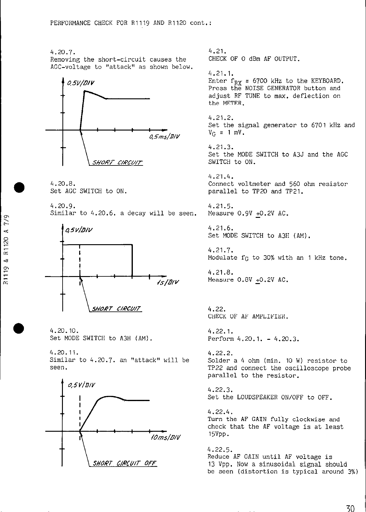
4.20.7.
Removing the short-circuit causes the
AGC-voltage to "attack" as shown below.
4 5ms/D/V
4.20.8.
Set AGC SWITCH to ON.
4.20.9.
Similar to 4.20.6. a decay will be seen.
45V/!!/V
4.21.
CHECK OF 0 dBm AF OUTPUT.
4.21.1.
Enter fRX = 6700 kHz to the KEYBOARD.
Press the NOISE GENERATOR button and
adjust RF TUNE to max. deflection on
the METER.
4.21.2.
Set the signal generator to
6701
kHz and
VG = 1 mV.
4.21.3.
Set the MODE SWITCH to A3J and the AGC
SWITCH to ON.
4.21.4.
Connect voltmeter and 560 ohm resistor
parallel to TPZO and TP21.
4.21.5.
Measure O.gV +0.2V AC.
4.21.6.
Set MODE SWITCH to A3H
(AM).
4.20.10.
Set MODE SWITCH to A3H (AM).
4.20.11.
Similar to 4.20.7. an "attack" will be
seen.
4.21.7.
Modulate fG to 30% with an 1 kHz tone.
4.21.8.
Measure 0.8V +0.2V AC.
4.22.
CHECK OF AF AMPLIFIER.
4.22.1.
Perform
4.22.2.
Solder a 4 ohm (min.
4.20.1. - 4.20.3.
10
W) resistor to
TP22 and connect the oscilloscope probe
parallel to the resistor.
4.22.3.
Set the LOUDSPEAKER ON/OFF to OFF.
4.22.4.
Turn the AF GAIN fuliy clockwise and
check that the AF voltage is at least
15VPP.
4.22.5.
Reduce AF GAIN until AF voltage is
13
Vpp. Now a sinusoidal signal should
be seen (distortion is typical around 3%)
30
Page 33
PERFORMANCE CHECK FOR R1119 AND RI120 cont.:
4.23.
CHECK OF SIMPLEX RELAY,
4.23.1.
Connect an ohm-meter to the antenna input terminal and to ground.
4.23.2.
Connect TP30 to TP29 with a piece of
wire and check that RElOl is activated.
4.23.3.
Check that the ohm-meter is showing a
short-circuit.
4.24.
SENSITIVITY MEASUREMENT.
4.24.1.
Choose fRX and fG according to table
4.24.11.
4.24.2.
Choose VG according to table
4.24.12.
(and refer to the definitions given in
section
5.1.).
NOTE: The sensitivity measured in A3J
mode must be 14 dB better than
the measured sensitivity in A3H
mode.
4.24.9.
Fine tune RF TUNE to max. meter reading
and reduce the meter reading to 0 dB
with RF GAIN.
4.24.10.
Remove the modulation from VG and notice
the drop on the meter reading.
In any case this must be at least 20 dB.
4.24.11.
Table 4.24.11.cnext page)
4.24.3.
Enter fRX to the KEYBOARD. Press the
NOISE GENERATOR button and adjust RF
TUNE to max. deflection on the METER.
4.24.4.
Set the signal generator to the stated
fG and VG.
4.24.5.
Set the MODE SWITCH to A3H.
4.24.6.
Connect the voltmeter to HEADPHONES via
a screened cable and adjust AF GAIN to
the meter reads 0 dB in the 1V range.
4.24.7.
Set AGC ON/OFF to OFF.
4.24.0.
Reduce RF GAIN until the meter reading
again is 0 dB.
31
Page 34

PERFORMANCE CHECK FOR
R1119
AND R1120 cont.:
MODE
I I
100
150
fRX
kHz - 149 kHz
kHz - 529 kHz
A3H 530kHz- 1.6MHz
(AM) 1.6 MHz - 4.0 MHz
4.24.12.
incl.
14.0
MHz
-
2182
30.0
Table 4.24.12.
MODE
100
150
BAND f-RX MHz fG MHz
kHz - 149 kHz 100 kHz
kHz -
529
kHz
MHz 1
kHz
VO (EMF) RG = 50 ohm
50
dB above 1 uV oi- 320 uV
30
dB above
30
dB above 1 uV or 32 uV
30
dB above 1 uV or 32 UV
25
dB above 1 uV or 18 UV 1
149
kHz
150
kHz
1
uV or 32 uV
1
A3H
(AM)
530
kHz -
1.599
kHz
1.599 kHz 30% with 1 kHz
1.6
MHz - 3.999 MHz 1.6 MHz
2.182
2.530
3.999 MHz
DISTRESS
2182
kHz
2.182
Fixed
4.0
MHz -29.999 MHz
4.000
5.290
6.999
7.000
9.900 MHz
13.999
280
kHz
529
kHz
530
kHz
920 kHz fRX modulated
MHz
MHz
kHz
MHz
MHz
MHz
MHz
MHz
14.000 MHZ
20.880
28.000 MHz
MHz
32
Page 35

5, ADJUSTMENT PROCEDURE FOR R1119 8 R1120
NOTE: The trimming cores are factory
sealed. Use normal cellulose thinner
to break the seal.
5.1.
DEFINITIONS USED.
5.1.1.
fRX q frequency to which the receiver
is adjusted (clarifier in the
middle of its operating range).
= signal generator frequency, i.e.
fG
the input frequency to the receiver.
= EMF of signal generator with
VG
proper generator impedance.
fAF = Audio frequency to HEADPHONES
and loudspeaker.
5.2.8.
Enter the stated fRX to the KEYBOARD.
Press the NOISE GENERATOR button and ad-
just RF TUNE to max. deflection on the
METER.
5.3.
ADJUSTMENT OF ?lSV SUPPLY UNIT.
5.3.1.
Connect the voltmeter to TPl.
5.3.2.
Adjust RlllO to -18V +0.2V.
5.3.3.
Connect the voltmeter to TP2.
5.3.4.
Adjust RI114 to +18V +0.2V.
5.2.
THE FOLLOWING SEQUENCE WILL OFTEN BE
USED:
5.2.1.
Connect the signal generator to the antenna input terminal on the receiver.
5.2.2.
Switch ON the receiver.
5.2.3.
Set LOUDSPEAKER ON/OFF to ON.
5.2.4.
Set AGC SWITCH to TELEX.
5.2.5.
Turn RF GAIN fully clockwise.
5.2.6.
Set AF GAIN to approx. middle position.
5.2.7.
Set the signal generator to the stated
fG and VG.
5.4.
ADJUSTMENT OF TCXO.
5.4.1.
The receiver must be ON for at least
5 minutes.
5.4.2.
Connect the counter to TP3.
5.4.3.
Adjust A1013 to 10,000,000 Hz.
5.5.
ADJUSTMENT OF CLARIFIER.
5.5.1.
Set the CLARIFIER to its center position.
5.5.2.
Set the MODE SWITCH to position 2182 kHz.
5.5.3.
Connect the counter to TP4.
5.5.4.
Adjust L1701 to 9000 HZ.
33
Page 36

ADJUSTMENT PROCEDURE FOR
R1119
& RllZO cont.:
5.6.
ADJUSTMENT OF 600 kHz GENERATOR.
5.6.1.
Set the MODE SWITCH to pos. A3J.
5.6.2.
Connect the diode probe to TP5.
5.6.3.
Adjust L1002 for max. deflection on the
TP-meter (approx. IV).
5.7.
ADJUSTMENT OF BFO CR1120 only).
5.7.1.
Set the CLARIFIER to its center posi-
tion.
5.7.2.
Set the MODE SWITCH to Al.
5.7.3.
Set the FILTER SWITCH to WIDE.
5.9.
ADJUSTMENT OF IF AMPLIFIER DETECTOR.
5.9.1.
Connect the signal generator to TP7
through a
5.2.2., 5.2.3.,
10
nF capacitor, execute
5.2.4., 5.2.5., 5.2.6.,
set the signal generator to fG q 599 kHz
and VG z
10
mV.
5.9.2.
Set MODE SWITCH to A3J.
5.9.3.
Slowly
reduce
VG until noise starts to
dim the AF tone; then increase VG 20 dB.
5.9.4.
Connect voltmeter to HEADPHONES via a
screened cable, and adjust AF GAIN so
that the meter reads 0 dB in the 1V
AC range.
5.9.5.
Adjust L805 for max. meter reading and
at the same time keep this on 0 dB by
reducing AF GAIN.
5.7.4.
Connect the frequency counter to TP6.
5.7.5.
Remove the BFO button.
5.7.6.
Adjust the potentiometer to 600,000 Hz.
5.7.7.
Mount the button with dot to dot, to
indicate the center position.
5.8.
ADJUSTMENT OF
5.8.1.
Enter fRx
16
: 11111
MHz GENERATOR.
kHz to the KEYBOARD,
(press 1 and C simultaneously) and exe-
cute 5.2.
5.6.2.
Connect the diode probe to TP4.
5.8.3.
Adjust
2V).
LlOOl
to max. voltage (approx.
5.9.6.
Set AGC SWITCH to OFF.
5.9.7.
Reduce RF GAIN until meter reading
again is 0 dB in the 1V range.
5.9.8.
Adjust L801 for max. meter reading and
at the same time keep this on 0 dB by
reducing RF GAIN.
5.10.
ADJUSTMENT OF IF FILTER.
5.10.1.
Execute 5.2. with fG = 600,O kHz,
VG = VG max. & fRx
5.10.2.
= 11111
kHz.
Connect the signal generator to TP7
through a
5.10.3.
10
nF capacitor.
Set the MODE SWITCH to A3H.
34
Page 37

ADJUSTMENT PROCEDURE FOR A1119 &
R1120
cont.:
5.10.4.
Turn the
L604 and
5.10.5.
trimming cores in L602, L603,
L605 fully counter clockwise.
Connect the diode probe to TPB.
5.10.6.
Adjust L601 to max. meter deflection.
5.10.7.
Adjust L602 to min. meter deflection.
5.10.8.
Adjust L603 to max. meter deflection.
5.10.9.
Adjust L604 to min. meter deflection.
5.10.10.
Adjust L605 to max. meter deflection.
5.10.11.
Remove the diode probe.
5.10.12.
Set VG to
10
mV and modulate the signal
generator 30 per cent with 1 kHz.
5.10.13.
Execute 5.9.3., 5.9.4., 5.9.6. and
5.9.7.
5.10.14.
Set the fG = 599,0 kHz and VG =
10
mV
unmodulated.
5.10.20.
Execute 5.9.3., 5.9.4., 5.9.6. and
5.9.7.
5.10.21.
Adjust L606 for max. meter reading and
keep this on 0 dB by reducing RF GAIN.
5.10.22.
Connect the frequency counter parallel
to the voltmeter, and thus measure the
frequency of the detected AF signal,
fAF.
5.10.23.
Adjust fG so that fAF varies between
300 Hz and 2700 Hz and find the frequen-
cy that gives max. meter deflection.
5.10.24.
Set meter reading to 0 dB by means of
the RF GAIN.
5.10.25.
Adjust fG so that fAF varies between
300
Hz and 2700 Hz and check the meter
reading is not less than -6 dB in this
frequency range.
5.10.14.
Modulate the signal generator with a
tone generator (modulation depth 30
per cent). Vary the modulation frequency between 300 Hz and 2700 Hz and find
the frequency giving max. meter deflec-
tion.
5.10.15.
Set meter reading to 0 dB by means of
the RF GAIN.
5.10.16.
Adjust the
300
Hz and 2700 Hz and check that the
modulation frequency between
meter reading is not less than -6 dB
in this range.
5.10.17.
Set the MODE SWITCH
5.10.18.
to
A3J.
Set the AGC SWITCH to TELEX.
THE FOLLOWING POINTS
IS ONLY TO BE EXECUTED FOR
5.10.26.
to
R1120.
5.10.44
AUX FILTER ADJUSTMENT EXECUTE 5.10.45.
AND
5.10.52.
5.10.26.
Set fG = 601 kHz and VG
lated. Execute
5.10.27.
5.10.2.
q 10
mV unmodu-
Set MODE SWITCH to Al and FILTER SWITCH
to INTERMEDIATE.
5.10.28.
Set the AGC SWITCH to TELEX.
5.10.29.
Turn RF GAIN fully clockwise.
Page 38

ADJUSTMENT PROCEDURE FOR R1119 & RI120 cont.:
a
5.10.30.
Set the BFO to fAF =
5.10.31.
1000
Hz.
Execute 5.9.3., 5.9.4., 5.9.6. and
5.9.7.
5.10.32.
Adjust L608 for max. meter reading and
at the same time keep this on 0 dB by
reducing RF GAIN.
5.10.33.
Adjust fG between 599.0 kHz and
601.0
kHz, and simultaneously adjust the BFO
so that fAF is approx.
1000
Hz. Find
the frequency fG that gives max. meter
reading and adjust this reading to 0 dB
by means of RF GAIN.
5.10.34.
Adjust fG between 599.0 kHz and 601.0
kHz and simultaneously adjust the BFO
so that fAF is approx.
1000
Hz. Check
that the meter reading is above -6 dB
in this frequency range.
5.10.35.
Set the FILTER SWITCH to NARROW and
fG = 600 kHz.
5.10.36.
Execute 5.2.4., 5.2.5., 5.2.6., 5.9.6.,
5.9.7. and adjust the BFO for fAF approx.
1000 Hz.
5.10.37.
Adjust L609 for max. meter reading and
keep the meter reading on 0 dB by adjusting the RF GAIN.
5.10.38.
Execute
5.10.33.
and 5.10.34. by varying fG in the frequency range 599.5 kHz
to
600.5
5.10.39.
kHz.
Set the FILTER SWITCH to VERY NARROW
and fG = 600 kHz.
5.10.42.
Execute
5.10.33.
by varying fG in the
frequency range 599.8 kHz to 600.2 kHz.
5.10.43.
Set fG to 599.8 kHz and 600.2 kHz respectively. Check that the meter rea-
ding is below -6 dB at both frequencies.
5.10.44.
Remove the signal generator from TP7,
and remove the plug from HEADPHONES.
R1119 TELEX AND RI120
AUX FILTER ADJUSTMENT EXECUTE
and
5.10.52.
5.10.45.
5.10.45.
Set MODE SWITCH to Al, FILTER SWITCH to
AUX and the AGC SWITCH to TELEX.
5.10.46.
Set fG
quency, VG =
q
1200
kHz - filter center fre-
10
mV unmodulated and exe-
cute 5.10.2.
Filter center frequency appears from
section TECHNICAL DATA.
5.10.47.
Turn RF GAIN fully clockwise and set
the BFO to fAF =
1000
Hz (except for
LSB filter adjustment).
5.10.48.
Execute 5.9.3., 5.9.4., 5.9.6. and
5.9.7.
5.10.49.
Adjust L606 for max. meter reading and
keep the meter reading on 0 dB by ad-
justing the RF GAIN.
5.10.50.
Adjust fG inside the min. pass band as
illustrated in TECHNICAL DATA, find the
frequency fG that gives max. meter rea-
ding and adjust this reading to 0 dB
by means of RF GAIN.
5.10.40.
Execute 5.2.4., 5.2.5., 5.9.6., 5.9.7.
and adjust the BFO for fAF approx.
1000 Hz.
5.10.41.
Adjust L610 for max. meter reading and
keep the meter reading on 0 dB by adjusting the RF GAIN.
5.10.51.
Adjust fG inside the min. pass band as
illustrated in TECHNICAL DATA. Check
that the meter reading is above -6 dB
in this frequency range.
36
Page 39

ADJUSTMENT PROCEDURE FOR RI119 & RI120 cont.:
5.10.52.
Remove the signal generator from TP7
and remove the plug from HEADPHONES.
5.11.
ADJUSTMENT OF FIRST AND SECOND MIXER.
5.11.1.
Execute 5.2. fRX = 3 kHz and VG q 0.
5.11.2.
Set the MODE SWITCH to A3H.
5.11.3.
Adjust R506 for min. deflection on
the TUNE meter.
5.11.4.
Connect the signal generator to TP9.
5.11.5.
For fRX =
10000
kHz, fG = 16608.5 kHz
modulated 30 per cent, 1 kHz and
VG =
5.2.7., 5.2.8., 5.9.3., 5.9.4., 5.9.6.
and 5.9.7.
5.11.6.
10
mV. Execute 5.2.4., 5.2.5.,
Remove the innercores of the six coa-
xial cables to the input of first
mixer.
5.11.7.
Adjust C5l2 and L503 for max. meter
reading and keep this on 0 dB by re-
ducing RF GAIN.
5.11.8.
Change fRX to 20000 kHz
10608.5
kHz and press the NOISE GE!
and fG to
\lE-
RATOR to unblock the receiver.
5.12.
MECHANICAL ADJUSTMENT OF THE FRONT-END
TUNING MECHANISM.
5.12.1.
Loosen the mechanical adjusting ring
mounted behind the front plate on the
TUNE shaft.
5.12.2.
Mount a 3x8 mm screw DIN84 and a 6 mm
spacing pipe in the square bar carrying the ferrite cores. Use the hole
nearest the front plate.
5.12.3.
Turn the square bars extreme left.
5.12.4.
Turn the adjusting ring clockwise
against the stop screw.
5.12.5.
Turn the TUNE shaft counter clockwise
so much that you can tighten the adjusting ring through the hole in the division plate behind the front plate.
5.12.6.
Turn the TUNE shaft fully counter clockwise.
5.12.7.
Adjust the ferrite cores for L201 and
L202 so that the ends of the cores are
flushing with the division plate.
5.12.8.
Adjust the ferrite cores for L301, L302,
L303, L304, L305, L306, L401, L402, L403,
L404, L405 and L406 so that the ends of
the cores are flushing in a distance Of
2 mm from the division plate.
5.11.9.
Adjust
C511
and L501 for max. meter
reading and keep the meter reading
on 0
5.11.10.
dB
by adjusting the RF GAIN.
Reconnect the six coaxial cables.
37
5.12.9.
Remove the screw and spacing pipe mounted in paragraph
5.13.
ADJUSTMENT OF
14 -
5.12.2.
30
MHz and 7 -
14
MHz
BAND FILTERS.
5.13.1.
Set the MODE SWITCH to A3H and set C408
and
C414
to middle position.
Page 40

ADJUSTMENT PROCEDURE
FOR
R1119 & RI120
cont.:
5.13.2.
Execute 5.2. with fG
VG
q 10
mV.
5.13.3.
= fRX = 28000 kHz
Execute 5.9.4., 5.9.6. and 5.9.7.
5.13.4.
Adjust L401, L404 and L406 for max.
meter reading and keep the meter rea-
ding on 0 dB by adjusting the RF GAIN.
5.13.5.
Execute 5.2.8. for fRX = fG = 14000 kHz.
5.13.6.
Adjust C408 and C414 for max. meter
reading and keep the meter reading on
0 dB by adjusting the RF GAIN.
5.13.7.
Execute 5.2.8. for fRx = fG = 28000 kHz.
5.13.8.
Repeat 5.13.4.,
5.13.5., 5.13.6.
and
5.13.7. successively until there is
no need for further adjustments.
NOTE: You must be very careful and ad-
just to exactly maximum.
5.13.9.
Remove the cable from HEADPHONE.
5.13.10.
Enter fRX
14000
kHz to the KEYBOARD.
Press the NOISE GENERATOR and turn
RF TUNE over its full range. Check
that there is only one maximum on the
METER. If a maximum is obtained for
the RF TUNE turned fully counter
clockwise it is necessary to screw
the ferrite cores to L401, L404
and
L406 a bit farther out of the coil
farmers
5.13.10.
and
then repeat 5.13.3. to
If a maximum is obtained for the RF
TUNE turned fully clockwise it is necessary to screw the ferrite cores L401,
L404 and L406 a bit farther into the
coil farmers and then repeat
to 5.13.10.
5.13.11.
5.13.3.
Lock the cores with the counter nut.
5.13.12.
Set
C413
and C418 to middle position.
5.13.13.
Execute 5.2.4., 5.2.5., 5.2.7., 5.2.8.,
5.9.4., 5.9.6. and 5.9.7. with fRX =
fG
q
10000
kHz and VG L-
10
mV modulated
30 per cent with 1 kHz.
5.13.14.
Adjust L402, L403 and L405 for max.
meter reading and keep the meter reading
on 0 dB by adjusting the RF GAIN.
5.13.15.
Execute 5.2.8. for fRX = fG = 7000 kHz.
5.13.16.
Adjust
C413
and C418 for max. meter reading and keep the meter reading on 0 dB
by adjusting the RF GAIN.
5.13.17.
Execute 5.2.8. for fRX = fG
5.13.18.
Repeat
5.13.17.
5.13.14., 5.13.15., 5.13.16. and
successively until there is no
q 10000
kHz.
need for further adjustments.
NOTE: You must be very careful and ad-
just to exactly maximum.
5.13.19.
Execute 5.2.8. for fRX = fG : 13999 kHz.
5.13.20.
Adjust
C413 and C418
for max. meter reading and keep the meter reading on 0 dB
by adjusting the RF GAIN.
NOTE: You must be very careful and ad-
just to exactly maximum.
5.13.21.
Lock the cores with the counter nuts.
5.13.22.
Perform a SENSITIVITY MEASUREMENT
(4.24.) in the frequency band of current interest and remove the cable from
HEADPHONES.
5.14.
ADJUSTMENT OF 4 - 7 MHz and 1.6 - 4 MHz.
5.14.1.
Set the MODE SWITCH to A3H.,
5.14.2.
Set
C312
and C318 to middle position.
38
Page 41

ADJUSTMENT PROCEDURE FOR
R1119 & RllZO
cont.:
5.14.3.
Execute 5.2., 5.9.4., 5.9.6. and 5.9.7.
with fRX = fG = 6999 kHz, VG =
10
mV
modulated 30 per cent with 1 kHz.
5.14.4.
Adjust L302, L304 and L305 for max. meter reading and keep the meter reading
on 0 dB by adjusting the RF GAIN.
5.14.5.
Execute 5.2.8. for fRX = fG : 4000 kHz.
5.14.6.
Adjust
C312
and
C318
for max. meter
reading and keep the meter reading on
0 dB by adjusting the RF GAIN.
5.14.7.
Execute 5.2.8. for fRx = fG = 6999 kHz.
5.14.8.
Repeat 5.14.4.,
5.14.7.
successively until there is
5.14.5., 5.14.6.
and
no need for further adjustment.
NOTE: You must be very careful and ad-
just to exactly maximum.
5.14.9.
Set C301,
C313
and C319 to middle posi-
tion.
5.14.10. 5.14.10.
Execute 5.2., Execute 5.2., 5.9.4., 5.9.6. and 5.9.7. 5.9.4., 5.9.6.
with fRX q fG = 3900 kHz, VG =
with fRx q fG = 3900 kHz, VG =
modulated 30 per cent with 1 kHz.
modulated 30
5.14.11.
per cent with
and 5.9.7.
10
mV
10
mV
1
kHz.
Adjust L301, L303 and L306 for max. meter reading and keep the meter reading
on 0 dB by adjusting the RF GAIN.
5.14.12.
Execute 5.2.8. for fRx = fG =
5.14.13.
Adjust
C301, C313
and
C319
1600 kHz.
for max. me-
ter reading and keep the meter reading
on 0 dB by adjusting the RF GAIN.
5.14.14.
Execute 5.2.8. for fG = fRx = 3900 kHz.
5.14.15.
Repeat 5
5.14.14.
'.14.11., 5.14.12., 5.14.13. and
successively until there is no
need for further adjustment.
NOTE: You must be very careful and ad-
just to exactly maximum.
5.14.16.
Lock the cores with the counter nut.
5.14.17.
Execute
5.15.
ADJUSTMENT OF 530 -
530
5.15.1.
5.13.22.
kHz AND
2182 kHz.
1600
kHz, 150 -
Set the MODE SWITCH to A3H.
5.15.2.
Set
C210
5.15.3.
to minimum capacity.
Execute 5.2., 5.9.4., 5.9.6..and 5.9.7.
with fG : fRX = 560 kHz and VG = 10 mV
modulated 30 per cent with 1 kHz.
5.14.4.
fG = fRX : 530 kHz push the NOISE GENERATOR button, but do not touch the
RF TUNE.
5.15.5.
Adjust
C210
to max. meter reading and
keep the meter reading on 0 dB by ad-
justing the RF GAIN.
5.15.6.
Execute 5.2.8. with fG = fRX
q 1599
kHz.
If no METER maximum is obtainable it
is necessary to screw the ferrite core
to L202 a bit farther out of the coil
farmers and then repeat
5.15.6.
5.15.7.
5.15.2. to
Set C209 to minimum capacity.
5.15.8.
Execute 5.2., 5.9.4., 5.9.6. and 5.9.7.
with fG = fRX =
modulated 30 per cent with
160
kHz and VG :
1 kHz.
10
mV
39
Page 42

ADJUSTMENT PROCEDURE FOR RI119 & RI120 cont.:
5.15.9.
fG = fRX = 150 kHz push the NOISE GENERATOR button. but do not touch the RF
TUNE.
5.15.10.
Adjust C209 to max. meter reading and
keep the meter reading on 0 dB by ad-
justing the RF GAIN.
5.15.11.
Execute 5.2.8. with fG q fRX q 529 kHz.
If no METER maximum is obtainable it
is necessary to screw the ferrite core
to L201 a bit farther out of the coil
farmers and then repeat 5.15.7. to
5.15.11.
5.15.12.
Lock the cores with the counter nut.
5.15.13.
Set MODE SWITCH to DISTRESS
5.15.14.
2182
kHz.
Execute 5.2., 5.9.4., 5.9.6. and 5.9.7.
with fG = fRX :
2182
kHz and VG :
10
mV
modulated 30 per cent with 1 kHz.
5.16.3.
Connect a passive probe to IC2020 pin 8
and to channel A on an oscilloscope.
Connect a passive probe to IC2020 pin
11
and to channel B on an oscilloscope.
Let the oscilloscope be positive triggered by channel A.
5.16.4.
Turn the CONTINUOUS TUNING clockwise.
5.16.5.
Check that the waveforms are as shown
below.
5.15.15.
Adjust the screw core of L209 to be in
level with the top of the coil former.
5.15.16.
Adjust C219 and L205 to max. meter reading and keep the meter reading on 0 dB
by adjusting the RF GAIN.
5.15.17.
Execute 5.13.22.
5.16.
ADJUSTMENT OF WHEEL I AND II.
5.16.1.
Switch the receiver ON.
5.16.2.
Push the NOISE GENERATOR button and the
decimal point key.
5.16.6.
Turn the CONTINUOUS TUNING counter
clockwise.
5.16.7.
Check that the waveforms are as shown
below.
5.16.8.
By adjusting the P.C.boards WHEEL I AND
WHEEL II the sections marked Al and A2
should be made equal.
NOTE: The adjustment should be done be-
fore remounting the front panel.
40
Page 43

6, NECESSARY ADJUSTMENTS AFTER REPAIR FOR R1119 AND R1120
In the following paragraphs reference is made to the ADJUSTMENT PROCEDURE FOR
Rlll9 AND RI120 and
Definition used: refer to 5.1.
Locations:
PERFORMANCE CHECK FOR
RI119 AND R1120.
refer to ADJUSTMENT LOCATIONS.
6.1.
Module No.
6.1.1.
100:
AERIAL SWITCH.
Execute 4.23.
6.1.2.
Enter the following fRx to the KEYBOARD
and press the NOISE GENERATOR button.
fRX = 240 kHz -
6.0 MHz - 10.0 MHz - 20.0 MHz.
6.1.3.
800
kHz - 2182 kHz -
When pressing the NOISE GENERATOR, ad-
just the RF TUNE to max. deflection on
the METER.
6.1.4.
Check that max. METER deflection is at
least
6.1.5.
1.5..
Set the MODE SWITCH to DISTRESS 2182 kHz.
6.1.6.
Press the NOISE GENERATOR and check
that the deflection on the METER is
at least 1.5.
6.4.
Module No. 400: BANDFILTER 7.0-14.0 MHz
and
14.0-30.0 MHz.
6.4.1.
Execute 4.15.,
5.13.
and 4.24. for the
coil section in question.
6.5.
Module No. 500:
6.5.1.
Execute
6.5.2.
5.11. and 4.17.
Enter fRX =
2.182
1st
and 2nd MIXER.
MHz to the KEYBOARD
and press the NOISE GENERATOR button.
6.5.3.
Check that the deflection on the METER
is at least
1.5.
6.6.
Module No. 600 or 700: IF FILTER.
z
s
*
,P
G
>
6.2.
Module No. 200: BANDFILTER
6.2.1.
Execute 4.15.,
5.15.
and 4.24. for the
O.Oi-1.6
MHz.
coil section in question.
6.3.
Module No. 300: BANDFILTER 1.6-4.0 MHz
and 4.0 - 7.0 MHz.
6.3.1.
Execute 4.15.,
5.14.
and 4.24. for the
coil section in question.
6.6.1.
Execute 5.10.,
6.7.
6.5.2.
and 6.5.3.
Module No. 800: IF AMPLIFIER, AGC AND
DETECTOR.
6.7.1.
Execute 5.9., 4.19., 4.x)., 6.5.2. and
6.5.3.
6.8.
Module No. 900: AUDIO AMPLIFIER.
I 41
Page 44

NECESSARY ADJUSTMENTS AFTER REPAIR FOR
Rlllg AND RI120
cont.:
6.8.1.
Execute
6.9.
Module No. 1000:
6.9.1.
4.21.
and 4.22.
DIVIDER-UNIT.
Execute 4.3., 5.4., 5.6., 5.8., 4.12.,
4.13.
6.10.
Module No.
and 4.24.
1100:
LOOP 1 FILTER AND +18V
SUPPLY-UNIT. -
6.10.1.
Execute 5.3., 4.6. with fRX =
4.12.
6.11.
Module No.
and
4.18.
1200:
VCO-UNIT.
10.0
MHz,
6.15.
Module No.
1600:
VCXO,
1st
LOOP 2 MIXER
AND LOOP 2 FILTER.
6.15.1.
Execute 4.8.1. to 4.8.5.tboth incl.),
4.9., 4.13. and 6.17. with the exception of point 4, 5, 9 and
6.16.
Module No.
1700:
CLARIFIER AND 2nd
10.
LOOP 2 MIXER.
6.16.1.
Execute 5.5. and 4.8.
6.17.
Module No. 1800: BFO-UNIT.
6.17.1.
Execute 5.7. and
4.11.
6.11.1.
Execute 4.7.,
6.12.
Module No.
6.12.1.
Execute 4.6.,
6.13.
Module No.
6.13.1.
Execute 4.7. and
6.14.
Module No.
6.14.1.
Execute
4.17.
4.12. and 4.17.
1300:
1400:
HARMONIC FILTER-UNIT.
4.12.
LOOP
4.12.
1500: VCO BUFFER-UNIT.
with the exception of
point 2, 3, 7 and 8.
1.
MIXER-UNIT.
6.18.
Module No.
6.18.1.
1900:
BAND CONTROL.
Press the KEYBOARD CLEAR, the NOISE
GENERATOR button and the KEYBOARD DECI-
MAL POINT.
6.18.2.
Turn the CONTINUOUS TUNING clockwise,
6.18.3.
Check that noise is heard from the loudspeaker until the DISPLAY shows
150.0
kHz then the receiver is blocked.
6.18.4.
Press the NOISE GENERATOR button. Check
that noise is heard from the loudspeaker.
6.18.5.
Turn the CONTINUOUS TUNING
6.18.6.
clockwise.
Check that noise is heard from the loudspeaker until the DISPLAY shows 530.0
kHz then the receiver is blocked.
42
Page 45

NECESSARY ADJUSTMENTS AFTER REPAIR FOR Rlllq AND RI120 cont.:
6.18.7. 6.18.7.
Repeat 4.18.4. to
4.18.6.
4.18.6.
and check that Repeat 4.18.4. to
and check that
the receiver has the following blocking the receiver has the following blocking
frequencies
14.0 MHz and 30.0 MHz. 14.0 MHz and 30.0 MHz.
6.18.8.
1.6 MHz, 4.0 MHz, 7.0
1.6 MHz, 4.0 MHz, 7.0
MHz, frequencies
MHz,
Execute 4.24.
6.19.
Module No. 2000: KEYBOARD CONTROL.
6.19.1.
Connect the passive probe to TP29 and to
the scope.
6.19.2.
Check that the wave form seen on the
scope is as shown below.
6.19.8.
Enter fRK = 222.2 kHz to the KEYBOARD.
6.19.9.
Repeat 6.19.6.
6.19.10.
Check that the voltmeter shows 5V DC on
the red wires and that the voltmeter
shows OV DC on the other wires.
6.19.11.
Enter fRK = 444.4 kHz to the KEYBOARD.
6.19.12.
Repeat 6.19.6.
6.19.13.
Check that the voltmeter shows 5V DC
on the yellow wires and that the volt-
meter shows OV DC on the other wires.
6.19.14.
Enter fRX = 888.8 kHz to the KEYBOARD.
6.19.3.
Execute 4.3.3., 4.3.4. and 4.5.
6.19.4.
-
Execute 6.18.1.
6.19.5.
Enter fRK =
6.19.6.
1111.1
6.18.7.
kHz to the KEYBOARD.
(both incl.).
Connect the voltmeter to the wires of
100
Hz, 1 kHz,
kHz,
100
kHz and
1
10
MHz data input terminals at the divi-
der-unit.
6.19.7.
Check that the voltmeter shows 5V DC on
the brown wires and the brown/black
wire and that the voltmeter shows OV DC
on the other wires.
6.19.15.
Repeat 6.19.6.
6.19.16.
Check that the voltmeter shows 5V DC
on the grey wires and that the voltmeter shows OV DC on the other wires.
6.20.
Module No.
6.20.1.
Execute
6.21.
4.5.1.
2100:
KEYBOARD.
- 4.5.5. (both incl.).
Module No. 2200: DISPLAY.
6.21.1.
Execute
6.21.2.
Execute
6.19.1.
4.5.1.
and
6.19.2.
- 4.5.5. (both incl.).
43
Page 46

NECESSARY ADJUSTMENTS AFTER REPAIR FOR
R1119 AND RI120 cont.:
6.22.
Module No. 2300 and 2400: WHEEL I AND II.
6.22.1.
Execute
5.16., 4.5.14.
-
4.5.18.
(both
incl.).
6.23.
Module No. 2500: INPUT FILTER.
6.23.1.
Execute
4.21.1.
6.24.
4.14., 4.15., 4.16.1., 4.16.2.,
- 4.21.5. (both incl.) and 4.23.
Module No. 2600: CLARIFIER CAPACITOR.
6.24.1.
Adjust knob for symmetrical variation
range.
6.24.2.
Execute 5.5. and 4.8.4. - 4.8.6. (both
incl.).
Page 47

7, FUNCTION CHECK R1119 AND R1120
NECESSARY TEST EQUIPMENT:
POWER SUPPLY E.g. SAILOR
N1405
MULTIMETER E.g. PHILIPS PM2503
If a signal generator is by hand this
can be used.
SIGNAL GENERATOR E.g. PHILIPS PM5326
INITIAL SETTINGS:
1.
Set the CLARIFIER to center position.
2.
Set the AGC SWITCH to TELEX MODE.
3.
Turn the RF GAIN fully clockwise.
4.
Turn the AF GAIN fully counter clockwise.
FUNCTION CHECK:
7.1.
Turn AF GAIN to suitable volume.
- r
,.L.
Check that the LOUDSPEAKER ON/OFF is
functional.
7.3.
Connect headphones to HEADPHONES socket.
7.4.
Check that the loudspeaker now is off
and the noise is heard in the head-
phones.
Remove the headphones.
” r
1.3.
Turn RF GAIN fully counter clockwise.
7.6.
Check that the noise in the loudspeaker
disappears.and the RF METER reading is
now approx. 5. Turn RF GAIN fully clock-
wise.
5.
Set the MODE SWITCH to DISTRESS
2182
kHz.
6.
Set the LOUDSPEAKER ON/OFF to ON.
7.
Set the BFO to center position
(RI120 only).
8.
Set the FILTER SWITCH to WIDE
(R1120 only).
9.
Connect the receiver to the power sup-
ply
(N1405).
10.
Connect the antenna input terminals to
the antenna or to the signal generator.
7.7.
Press the NOISE GENERATOR button.
7.8.
Check that the RF METER reading is at
least
7.9.
Check that the DISPLAY shows
7.10.
1.5.
2182
kHz.
Set the MODE SWITCH to A3J.
- . .
I. Il.
Press the KEYBOARD C. The DISPLAY shows
000000.
7.12.
Check that no noise is heard from the
loudspeaker.
7.13.
Press the KEYBOARD C and 1 simultaneously.
The DISPLAY shows
111111.
45
7.14.
Repeat
7.13.
for C and 2, 3 ---- 9,0.
Page 48
FUNCTION CHECK Rlllg AND RI120 cont.:
7.15.
Press the KEYBOARD C and the NOISE GENERATOR button. The DISPLAY shows
00000.0.
Check that noise is heard from the
loudspeaker.
7.16.
Press the KEYBOARD decimal point. The
DISPLAY shows 00000.0.
7.17.
Turn the CONTINUOUS TUNING clockwise
until the DISPLAY shows
00150.0
kHz.
Check that no noise is heard from the
loudspeaker.
7.18.
Press the KEYBOARD 0 and turn the CONTINUOUS TUNING. The displayed figure
must not change.
7.19.
Press the KEYBOARD C and the NOISE
GENERATOR button.
7.20.
Turn the CLARIFIER extreme clockwise
and check that the beat note heard
from the loudspeaker change.
7.27. (RI120 only)
Set the CLARIFIER to center position.
7.28. CR1120 only)
Turn the BFO to center position and
then clockwise until a proper beat note
is heard from the loudspeaker.
7.30. (Rl120 only)
Connect the voltmeter to HEADPHONES via
a screened cable and adjust AF GAIN
to the meter reads 0 dB in the 0.3V
range.
7.31.
(RI120 only)
Set the AGC ON/OFF to OFF.
7.32. CR1120 only)
Reduce RF GAIN until the meter reading
is 0 dB again.
7.33. (R1120
only)
Press the KEYBOARD decimal point.
7.34. (R1120 only)
Turn the CONTINUOUS TUNING clockwise
until the DISPLAY shows 00000.4 kHz.
7.35. CR1120 only)
Check that the meter reading is&-l0 dB.
7.21.
Repeat 7.20. within the CLARIFIER
extreme counter clockwise.
7.22. (Fill20
only)
Set the MODE SWITCH to Al.
7.23. (R1120 only)
Adjust the BFO until no beat note is
heard from the loudspeaker.
Check that the BFO now is in its coun-
ter position.
7.24. CR1120
only)
Turn the BFO extreme clockwise.
Check that a beat note is heard from
the loudspeaker.
7.25. CR1120 only)
Repeat 7.24. with the BFO extreme
counter clockwise.
7.26. (Rll20 only)
Set the FILTER SWITCH to VERY NARROW.
7.36. (RI120 only)
Set the FILTER SWITCH to NARROW.
7.37. (RI120 only)
Adjust the RF GAIN until the meter rea-
ding is 0 dB again.
7.38. CR1120 only)
Turn the CONTINUOUS TUNING clockwise
until the DISPLAY shows
00001.0
kHz.
7.39. (R1120 only)
Check that the meter reading
is+-10
dB.
7.40. (RI120 only)
Set the FILTER SWITCH to INTERMEDIATE.
7.41. CR1120 only)
Repeat 7.37.
7.42. (RI120 only)
Turn the CONTINUOUS TUNING clockwise
until the DISPLAY shows
00001.5
kHz.
46
Page 49

FUNCTION CHECK Fill19 AND R1120 cont.:
7.43. (R1120 only)
Check that the meter reading is&
-10
dB.
7.44. CR1120 only)
Set the FILTER SWITCH to WIDE.
7.45. (R1120 only)
Repeat 7.37.
7.46. (R1120 only)
Turn the CONTINUOUS TUNING clockwise
until the DISPLAY shows 00003.0 kHz.
7.47. (R1120 only)
Check that the meter reading is&
-10
dB.
7.48. CR1120 only)
Set the FILTER SWITCH to AUX.
7.49. CR1120 only)
If an AUX FILTER is fitted find a radio
station and check that the filter band-
width is correct.
7.50. (R1120 only)
Set the FILTER SWITCH to WIDE.
7.51. CR1120 only)
Set the MODE SWITCH to A2.
Set the AGC SWITCH to TELEX.
Turn the RF GAIN fully clockwise.
7.52. (R1120 only)
Press the KEYBOARD C and the NOISE
GENERATOR button.
7.58. (RI120 only)
Turn the CLARIFIER extreme counter
clockwise.
7.59.
Press the KEYBOARD decimal point.
7.60.
Check that the RF METER shows approx. 3.
7.61.
Turn the CONTINUOUS TUNING until the
DISPLAY shows 00000.5 kHz.
7.62.
Check that the RF METER shows approx. 0.
7.63.
Set the MODE SWITCH to A3H (AM)'.
7.64.
Check that the RF METER shows approx. 3.
7.65.
Turn the CONTINUOUS TUNING clockwise.
7.66.
Check that the RF METER deviation be-
gins to drop when the DISPLAY shows
00003.0 kHz and that the RF METER is
approx. 0 when the DISPLAY shows
00010.0
kHz.
7.67. CR1119 only)
Set the MODE SWITCH to TELEX.
7.53. CR1120 only)
Press the KEYBOARD decimal point.
Turn the CONTINUOUS TUNING clockwise.
7.54. CR1120 only)
Check that the RF METER deviation be-
gins to drop when the DISPLAY shows
00003.0 kHz and that the RF METER is
approx. 0 when the DISPLAY shows
00010.0
kHz.
7.55. CR1120 only)
Set the MODE SWITCH to A3J.
7.56. CR1120 only)
Disconnect the meter from HEADPHONES.
7.57. (R1120 only)
Press the KEYBOARD C and the NOISE GE-
NERATOR button.
7.68. (R1119 only)
If an AUX filter is fitted. Check the
filter bandwidth by means of a suitable
broadcast station or the signal genera-
tor.
7.69. (R1119 only)
Set the MODE SWITCH to A3H (AM).
7.70.
Set the MODE SWITCH to A3J (SSB).
7.71.
Set the AGC SWITCH to ON.
7.72.
Press the KEYBOARD C and the NOISE GENE-
RATOR button.
7.73.
Press the KEYBOARD decimal point.
47
Page 50

FUNCTION CHECK
Fill19
AND
RI120 cont.:
7.74.
Turn the CLARIFIER extreme counter
clockwise.
7.75.
Notice the position of the RF METER
pointer.
7.76.
Turn the CONTINUOUS TUNING counter
clockwise.
7.77.
Check that it takes approx. 3 sets.
after turning the CONTINUOUS TUNING
until the pointer of the RF METER is
approx. 0.
7.78.
If a signal generator is by hand,
set fC : fRK, VC = 1 mV modulated
30 per cent with 1 kHz.
1.79.
If no signal generator is by hand,
connect a DC voltmeter to TPll.
7.86.
Turn the DIMMER extreme clockwise.
7.87.
Check that the DISPLAY and the RF METER
is illuminated.
7.80.
Set the MODE SWITCH to A3H (AM).
7.81.
Enter fRK
q
1.999
MHz to the KEY-
BOARD.
7.82.
Press the NOISE GENERATOR and ad-
just the RF TUNE to max. deflection
on the RF METER and check that the
RF METER deflection is at least
1.5.
7.83.
Check that a
1000
Hz tone is heard
from the loudspeaker if a signal generator is used.
7.84.
If no signal generator is used check
that the voltmeter measures 15V +
1.5V DC.
7.85.
Repeat 7.82. -
7.64.
for
fRK q fC =
3.999 - 5.999 - 7.999 - 9.999 - 11.999 -
13.999 - 15.999 - 17.999 - 19.999 -
21.999 - 23.999 - 25.999 - 27.999 -
29.999 MHz.
48
 Loading...