

Page 1

OPERA T OR MANUAL
RADIOTELEPHONY
HF SSB RE2100
SAILOR
COMPACT 2000 PROGRAMME
Page 2

FOR YOUR INFORMATION
All information and illustrations in this manual are based on the information available
when this manual was printed.
We make reservations concerning errors in this manual, and all specifications are
subject to change without further notice.
S.P. Radio A/S has the copyright, all rights are reserved. Copyright 1993-95.
Doc. No.: B2100GB Issue: D/9510
RE2100/C2140/R2120/T
Page 3

CONTENTS
1 GENERAL INFORMA TION
1.1 2182 kHz 1-1
1.2 Distress 1-1
1.3 Urgency signal 1-1
1.4 Safety Signal 1-1
1.5 Silence Periods 1-1
1.6 Operating 1-1
1.7 Simplex Communication 1-1
1.8 Duplex Communication 1-1
2 CONTROLS
3 SYSTEM DESCRIPTION
3.1 General 3-1
3.2 Simplex Radiotelephone Standard System 3-1
3.3 Duplex Radiotelephone 3-1
3.4 Telegraphy 3-1
3.5 Remote Control 3-1
3.6 DSC/Telex 3-1
4 READ-OUT
4.1 Radiotelephony 4-1
4.2 Radiotelephony and Telegraphy 4-1
5 OPERATION
5.1 Operating Hints 5-1
5.2 Initial Settings 5-1
5.3 Select a Frequency 5-1
5.4 Clear the TX Display 5-1
5.5 Select Mode 5-1
5.6 Turn OFF/ON the AGC 5-2
5.7 Turn OFF/ON the Squelch 5-2
5.8 Reduce/Increase the Tx Power Level 5-3
5.9 DIM the Display 5-3
5.10 Tune the Receive Frequency 5-3
5.11 Clarify the Received Signal 5-3
5.12 Return to Receiver Frequency Mode from Clarifier Mode 5-3
5.13 Select Built -in Dummy Load for Tx Output Power Test 5-4
5.14 Test the Alarm Signal Generator 5-4
5.15 Start a New Transmitter Tune-up Cycle 5-4
5.16 Interrupt a Transmitter Tune-up Cycle 5-4
6 CHANNEL MODE OPERATION
6.1 Operation in CH Mode 6-1
6.2 Select an ITU Channel 6-1
6.3 Select a Quick Select Channel Number 6-1
6.4 Store a New Frequency Pair in Quick Select Channel 0-99 6-1
6.5 Change the Content of a Quick Select Channel 6-1
6.6 Delete the Content of a Quick Select Channel 6-2
6.7 Check which Quick Select Channel Numbers are already Used 6-2
6.8 Convert a Selected Channel to a Corresponding Frequency Pair 6-2
Convert a Frequency Pair to a Corresponding Quick Select Channel Number
6.9
RE2100/C2140/R2120/T
6-2
Page 4

7 SCANNING OPERA TION
7.1 Use the Scan Programme 7-1
7.2 Build-up a Scan Programme 7-1
7.3 Start a Scan Programme 7-1
7.4 Stop a Scan Programme 7- 1
7.5 Check the Content of a Scan Programme 7-1
7.6 Delete a Channel from a Scan Programme 7-2
8 DISTRESS CALL PROCEDURE
8.1 Distress Call on 2182 kHz 8-1
8.2 Stop the Alarm Signal 8-1
8.3 Transmit the Alarm Signal on a Frequency other than 2182 kHz 8-1
8.4 Ship’s Identity Information 8-2
9 SWEEP OPERATION
9.1 General 9-1
9.2 Programming of the Sweep Programme 9-1
9.3 Start/Stop of the Sweep Programme 9-3
9.4 Delete a Frequency from the Sweep Programme 9-4
10 DUPLEX OPERATION
10.1 General 10-1
10.2 Select Duplex Mode by means of Frequencies 10-1
10.3 Select Duplex Mode by means of Channel Number 10-2
10.4 Return to Simplex Mode 10-2
11 TELEGRAPHY OPERATION
11.1 General 11-1
11.2 Connection Unit H2185 11-1
11.3 Select Telegraphy Mode 11-1
11.4 Start Transmission of Telegraphy 11-1
11.5 Stop Transmission of Telegraphy 11-2
11.6 Enter BFO Control Mode 11-2
11.7 Return from BFO Control Mode 11-2
12 MANUAL TUNE-UP PROCEDURE 250W SYSTEM
13 MANUAL TUNE-UP PROCEDURE 600W/1200W SYSTEM
14 OPEN/GROUNDED AERIAL
14.1 Ground the Aerial 14-1
14.2 Open the Aerial 14-1
14.3 Return from the Open or Grounded Aerial 14-1
15 ERROR MESSAGES 250W SYSTEM
15.1 Error Messages from the Receiver/Exciter RE2100 15-1
15.2 Error Messages from the Transmitter T2130 15-1
15.3 Example 15-1
16 ERROR MESSAGES 600W/1200W SYSTEM
16.1 Error Messages from the Receiver/Exciter RE2100 16-1
16.2 Error Messages from the Transmitter T2131/T2135 16-1
16.3 Example 16-1
RE2100/C2140/R2120/T
Page 5

17 OPERA TION REMOTE CONTROL UNIT
17.1 General Description 17-1
17.2 Stand-By Mode 17-1
17.3 Active Mode 17-1
17.4 Intercom Mode 17-1
17.5 Radiotelephony Call 17-1
17.6 Distress Call 17-2
18 QUICK SELECT/FREQUENCY T ABLE
19 QUICK SELECT CHART
RE2100/C2140/R2120/T
Page 6

Page 7
1 GENERAL INFORMATION
1
2
5
8
DIM
LOAD
DUMMY
RX
kHz
TX
kHz
AGC
1.1 2182 kHz
The international distress and call frequency 2182 kHz
may be used for distress communication, urgency and
safety transmissions, as well as ordinary calls between
stations participating in the maritime mobile service.
The distress call must have absolute priority over all
other transmissions.
1.2 Distress
The radiotelephone distress procedure must consist
of:
- The alarm signal (whenever possible) followed by:
- the distress signal MAYDAY (three times).
- The words “this is”.
- The name of the ship in distress (three times).
- MAYDAY (once).
- The name of the ship.
- The position expressed in longitude and latitude
or by bearing to a familiar geographic point.
- The nature of the distress and the kind of assistance needed.
- Any other information which might facilitate the
rescue, e.g. how many men on board.
1.3 Urgency signal
The urgency signal consists of three repetitions of the
group of words PAN PAN.
The message must be addressed to a particular station or to all stations. The signal indicates that the
calling station has a very urgent message to transmit
concerning the safety of a ship or the safety of a
person.
The urgency signal must have priority over all other
communications except distress.
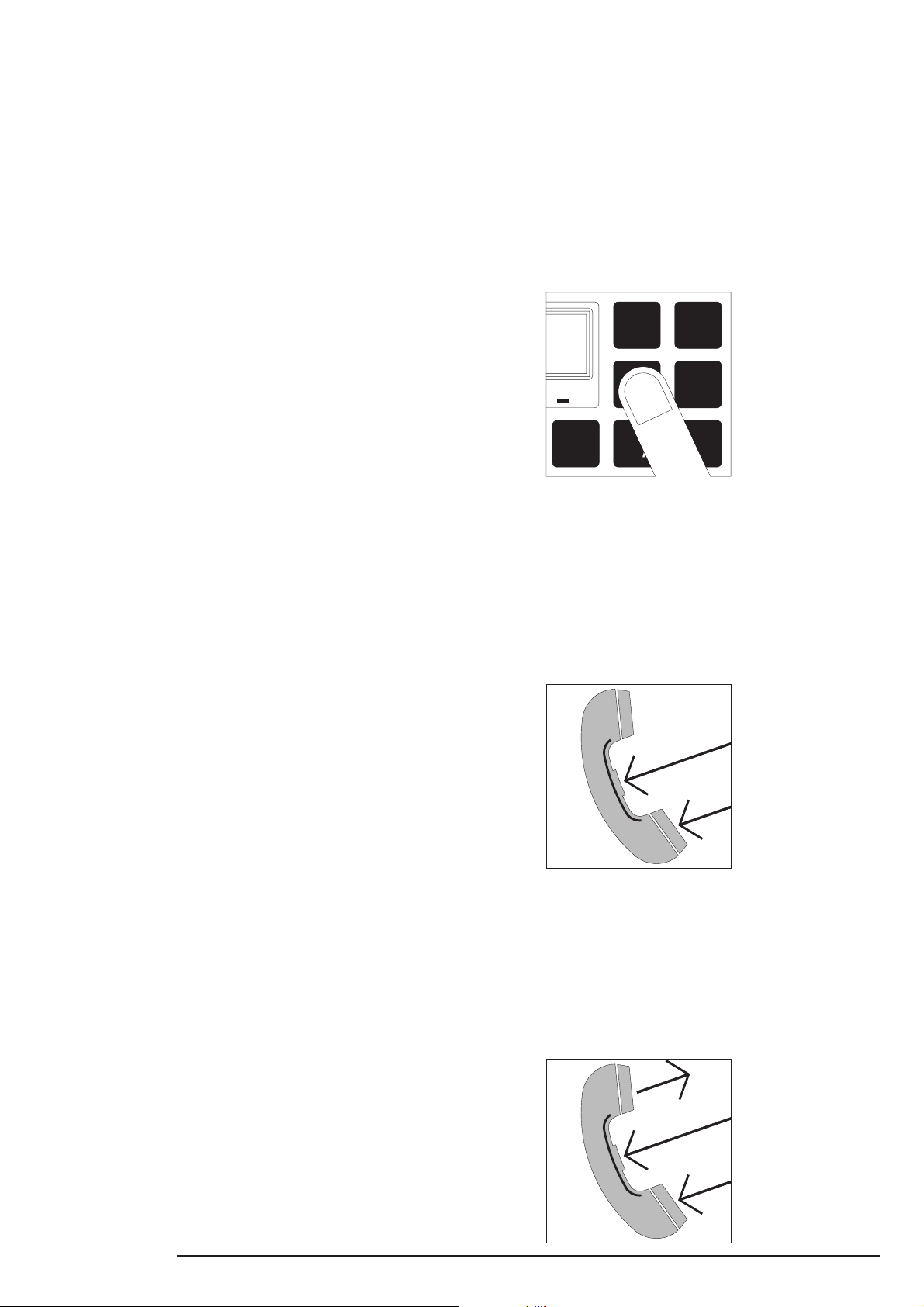
1.6 Operating
The operating panel is provided with a very high quality
push-button keyboard panel offering an attractive solid
feel. Furthermore, keyed operations are instantly confirmed by means of the display read-out.
To ensure safe operation under all conditions, the
keyboard is fitted with night-time illumination.
1.7 Simplex Communication
The HF SSB Radiotelephone is normally operated in
the simplex/semi-duplex mode. This means that
communication only takes place in one direction at a
time.
To operate the system you have to press the handset
switch and deliver your message, which must be
ended with the word “over”. The switch is now released, allowing the other person to reply.
1.4 Safety Signal
The safety signal consists of the word SECURITY.
The signal indicates that the station is about to transmit
a message containing an important navigational or
important meteorological warning.
The safety signal must be transmitted on 2182 kHz,
and the message which follows the call should be
transmitted on a working frequency.
1.5 Silence Periods
Stations normally watch keeping on 2182 kHz must
endeavour to watch for three minutes twice each hour
beginning at xx hour 00 and xx hour 30 UTC, the so
called silence periods.
During silence periods distress and urgency traffic are
allowed only.
However, safety signals may be transmitted during the
last 10 seconds of a silence period.
1.8 Duplex Communication
If your HF SSB Radiotelephone is fitted with the Duplex
Receiver R2120, you have the opportunity to communicate in full duplex mode.
This means that communication can take place in both
directions at the same time.
To operate the system you just have to press the
handset switch and then make your conversation.
RE2100/C2140/R2120/T - GENERAL INFORMATION 1-1
Page 8
VOL
O
F
F
RF
SIGNAL
0 .5
TX
POWER
CURRENTAE
21 3
H3E AGC
RX
kHz
TX
kHz
1
4
2
5
3
6
29073
FREQ
SEND
ALARM
FREQ
2182
TUNE
CLARIF
TEST
ALARM
RX
TX
CH
SC
AGC
POWER
SQ
ADD
DIM
DUMMY
LOAD
MODE
DEL
7
0
8 9
STOP
.
ENT
1-2 RE2100/C2140/R2120/T - GENERAL INFORMATION
Page 9

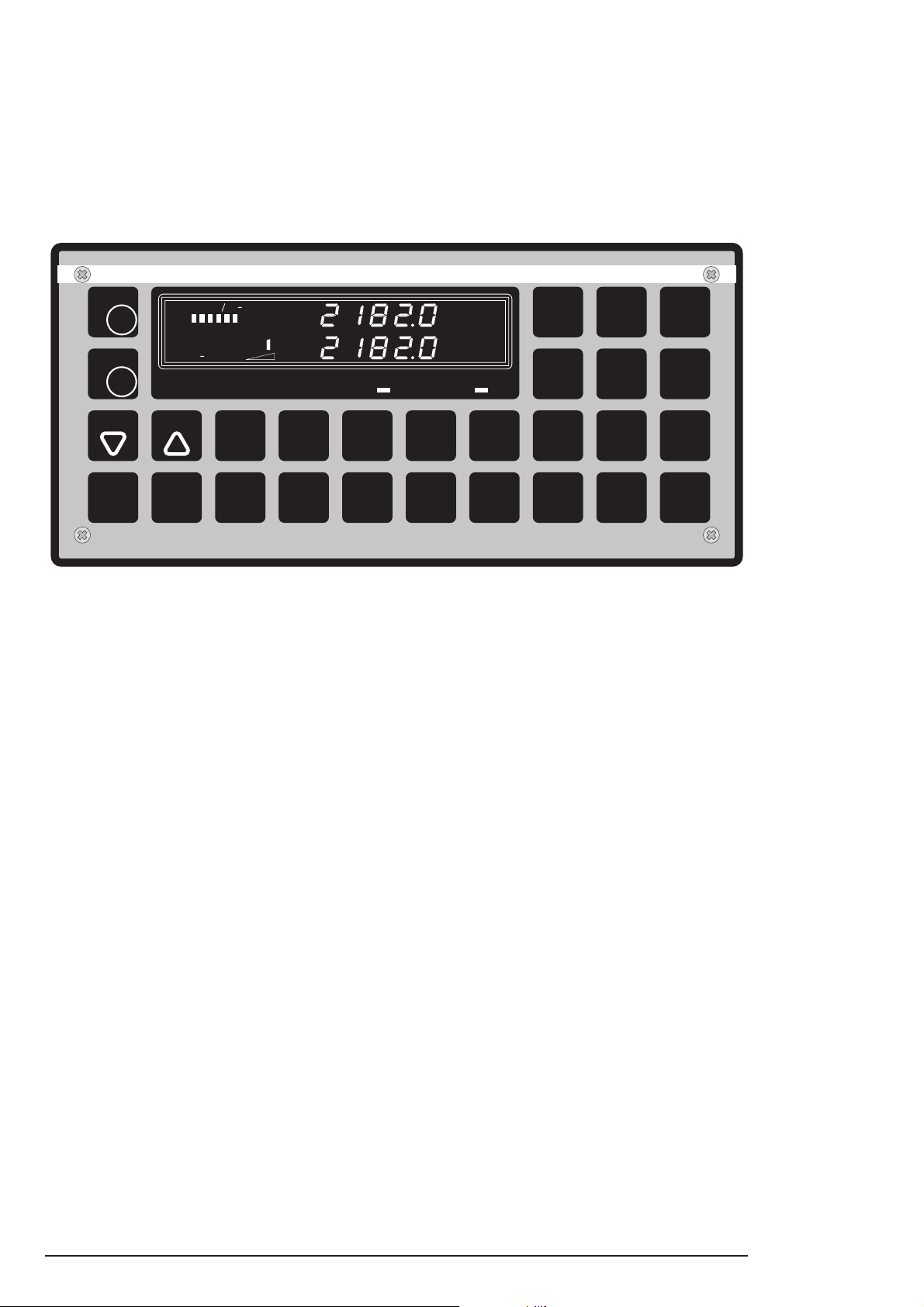
2 CONTROLS
.
CH
CH
TX
VOL
O
F
F
Volume control and on/off switch for the mains.
RF
Manual RF gain control.
Sets the decimal point for the frequency in kHz.
(Digits 0-99)
SQ
Adds the RX/TX frequency
ADD
to the channel number.
FREQ
Tunes the receive frequency down.
FREQ
Tunes the receive frequency up.
TUNE
Switches between clarifier (10 Hz steps) and
CLARIF
tune of receive frequency.
RX
Selects receive functions or converts a channel
number to the corresponding frequency.
CH
Selects channel functions.
TX
Selects transmit functions or converts a
channel number to the corresponding frequency.
AGC
TX
TX
Reduce/increase the transmitter output
POWER
power.
Selects the built-in dummy load in the
DIM
aerial coupler, and the TX frequency
DUMMY
LOAD
2206.4 kHz is automatically selected.
(Digits 0-99)
TUNE
Resets the tune memory at the selected
CLARIF
frequency and starts a new tune-up cycle.
Deletes the RX/TX fre-
DEL
quency from the channel.
Transmits the distress signal when pressed
SEND
ALARM
simultaneously with TEST ALARM.
2182
Selects the distress frequency 2182 kHz.
TEST
ALARM
Acoustic check of the alarm signal generator.
Reduces/increases the display illumination and
DIM
switches on/off the display and keyboard panel
DUMMY
LOAD
illumination.
AGC
POWER
Switch the AGC function on/off.
SQ
ADD
Turns the squelch function on/off.
Selects modulation type J3E, R3E, H3E and
optionally LSB (J3E lower side band).
MODE
In conjunction with R2120T the R3E mode is
DEL
changed to CW mode.
SC
Selects the scan programme.
7
Digits from 1 to 9 and 0.
Terminates the keying-in sequence, stops the
STOP
alarm signal, stops the scanning, and stops the
ENT
TX tuning.
RE2100/C2140/R2120/T - CONTROLS 2-1
Page 10

Page 11
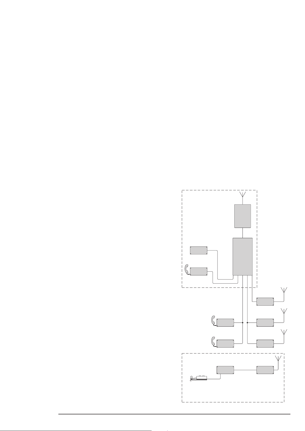
3 SYSTEM DESCRIPTION
H2054
RE2100
TRANSMITTER
COUP-
AERIAL
LER
Remark:
C2140 RM2150
RM2151
R2120
MORSE KEY
C2140
The interconnection between the telegraphy
units and the standard equipment for simplex
Simplex Radiotelephone
Standard System
28900B-GB
H2185 R2120T
radiotelephony is shown in chapter 11,
Telegraphy Operation.
Units for Telegraphy
Loudspeaker
Receiver/Exciter
Duplex Receiver
DSC Watchreceiver
Telex/DSCControl Unit
ReceiverCW Unit
Operation
Duplex/Telegraphy
Control Unit
3.1 General
The Compact HF SSB Programme 2000 includes all
facilities that forms a modern maritime short wave
radio station.
The equipment consists of a number of separate units,
which can be interconnected to give a sophisticated
and highly advanced maritime communication system.
The divided structure gives a very flexible system,
which can be fitted to fulfil all needs and wishes of the
customers. This gives a very cost efficient system,
because the customer only pays for the facilities he
actually needs.
3.2 Simplex Radiotelephone Standard
System
The system is built up around four units, which form the
standard system for simplex radiotelephony. These
four units are pointed out on the block diagram by a
surrounding broken line.
The standard system is delivered in three different
versions, with the following power levels: 250W, 600W
and 1200W. The power level is only depending on the
size of the transmitter and aerial coupler, which means
that the Receiver/Exciter Unit RE2100 is commen for
all versions of the system.
3.5 Remote Control
The Standard Simplex/Duplex system can be remote
controlled by the Control Unit C2140, which can be
placed up to 100 meters away from the Transmitter.
The system can handle up to five Control Units C2140,
depending on the number of other optional units.
Furthermore, it is possible to use the Control Unit
C2140 as an intercom, which means that a conversation can take place between two Control Units
C2140 or between a Control Unit C2140 and the
Receiver/Exciter Unit RE2100.
3.6 DSC/Telex
The standard system can be extended with the DSC
Watchreceiver RM2150 and/or the Telex/DSC RM2151.
The operation of these two units and the principle of
DSC (Digital Selective Calls) are described in the
separate operator manual: “OPERATOR MANUAL
DSC HF SSB RM2150/RM2151”.
The standard system is fully controlled from the Receiver/Exciter Unit RE2100. This unit is provided with
a high quality push-button keyboard, and a display
where keyed operations are instantly confirmed.
The standard system can be extended by optional
equipment to fulfil almost any requirement. This optional equipments is described below.
3.3 Duplex Radiotelephone
The standard system can be extended to duplex
operation by means of the Duplex Receiver R2120.
This unit has its own antenna for reception and is fully
controlled from the Receiver/Exciter Unit RE2100.
3.4 Telegraphy
The standard system can be extended to telegraphy
operation by means of the Duplex/Telegraphy Receiver R2120T, which is a special version of the Duplex
Receiver. This version includes a very narrow intermediate filter and a BFO circuit (Beat Frequency Oscillator).
Furthermore, to obtain the facility of telegraphy, the
system must also include the CW Unit H2185. This unit
includes a Side Tone Oscillator, power supply for
Duplex/Telegraphy Receiver R2120T and connectors
for the Morse Key and Headset.
RE2100/C2140/R2120/T - SYSTEM DESCRIPTION 3-1
Page 12

Page 13
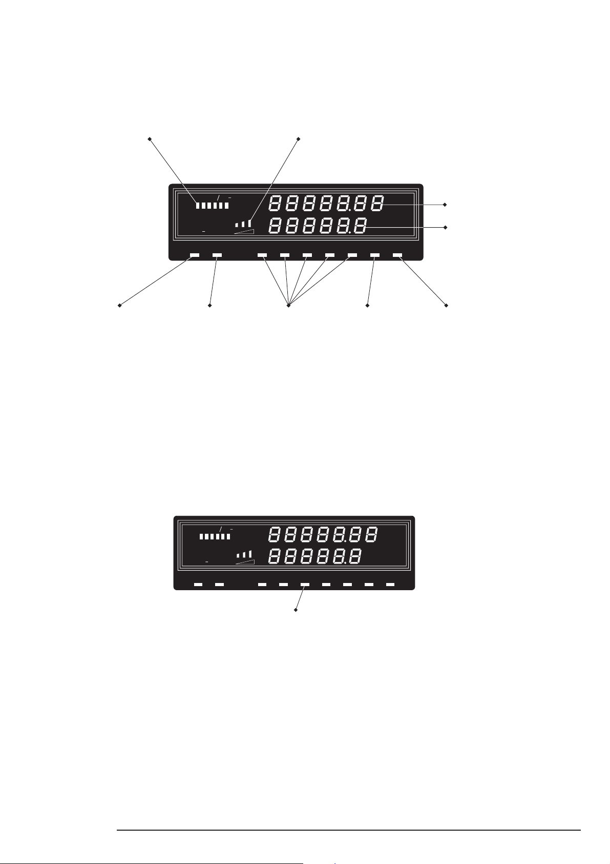
4 READ-OUT
4.1 Radiotelephony
Displayes signal strength in RX mode.
Displayes aerial current in Amps
when transmitting.
0
.5 21 3
TX
POWER
DUMMY
28901
Lights up when dummy
load is selected.
Lights up when
TX is tuning.
CURRENTSIGNAL AE
Displayes the TX power level.
H3E TLXJ3ELSBTUNELOAD R3E
The selected mode
lights up.
4.2 Radiotelephony and Telegraphy
To operate your system in Telegraphy mode, the
original front foil at the Receiver/Exciter Unit RE2100
has to be replaced by the one below.
This new front foil is delivered together with the Duplex/
Telegraphy Receiver R2120T.
The only difference between the two front foils is the
mode indicator for CW (Continuous Wawes), which
replaces the mode indicator for R3E.
RX
kHz
TX
kHz
AGCSQ
Lights up when
squelch is on.
Displayes receive frequency in kHz
or channel number.
Displayes transmit frequency in kHz.
Lights up when
AGC is on.
29309
0
TX
DUMMY
CURRENTSIGNAL AE
.5 21 3
POWER
RX
kHz
TX
kHz
H3E TLXJ3ELSBTUNELOAD CW
The CW lights up
when the Telegraphy mode is selected
AGCSQ
RE2100/C2140/R2120/T - READ-OUT 4-1
Page 14

Page 15
5 OPERATION
POWER
TX
0
CURRENTSIGNAL AE
.5 21 3
RX
kHz
kHz
TX
J3E AGCSQ
POWER
TX
0
CURRENTSIGNAL AE
.5 21 3
RX
kHz
kHz
TX
J3E AGCSQ
POWER
TX
0
CURRENTSIGNAL AE
.5 21 3
RX
kHz
kHz
TX
J3E AGCSQ
POWER
TX
SIGNAL
0 .5
AE CURRENT
21 3
TX
kHz
RX
kHz
SQR3E AGC
5.1 Operating Hints
When TX mode is selected, the full stop sign in the TX display
flashes. After 10 secs, the full stop sign will stop flashing and
the receiver/exciter will return to RX mode.
Default settings are: AGC on, Squelch on, and Full TX-Power.
When pressing the handset key, the tune lamp is alight, and
when it extinguishes, the set is ready for operation.
5.2 Initial Settings
Turn VOL/OFF knob to approx. mid position and turn RF gain
knob fully clockwise.
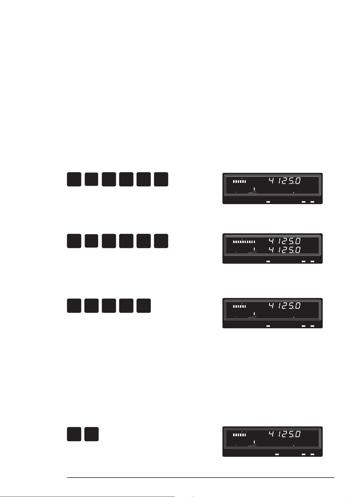
5.3 Select a Frequency
1. Receive frequency e.g. 4125.0 kHz.
Press:
RX
4
1
2
STOP
ENT
5
2. Transmit frequency e.g. 4125.0 kHz.
Press:
TX
4
1
2
STOP
ENT
5
5.4 Clear the TX Display
Press:
TX
0
0
STOP
0
ENT
Read-out:
Read-out:
Read-out:
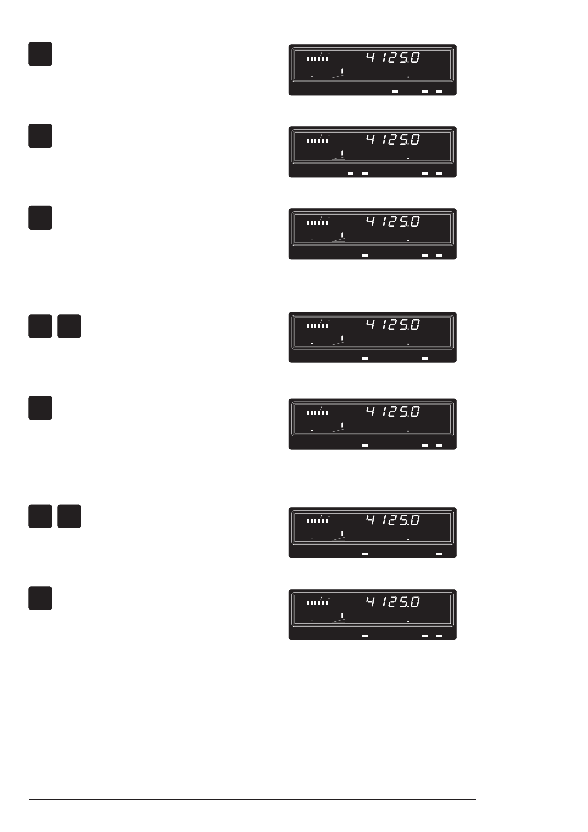
5.5 Select Mode
For frequencies below 1605 kHz, H3E mode is automatically
selected.
For frequencies above 1605 kHz, J3E upper sideband is
automatically selected.
J3E = SSB with suppressed carrier and upper sideband
R3E = SSB with reduced carrier and upper sideband
H3E = AM with upper sideband
LSB/J3E = SSB with suppressed carrier and lower sideband
To change the mode press:
RX
RE2100/C2140/R2120/T - OPERATION 5-1
MODE
Read-out:
DEL
Page 16
Press:
POWER
TX
SIGNAL
0 .5
CURRENTAE
21 3
TX
kHz
RX
kHz
SQH3E AGC
POWER
TX
SIGNAL
0 .5
AE CURRENT
21 3
TX
kHz
RX
kHz
LSB J3E SQ AGC
POWER
TX
0
CURRENTSIGNAL AE
.5 21 3
RX
kHz
kHz
TX
J3E AGCSQ
POWER
TX
SIGNAL
0 .5
CURRENTAE
21 3
TX
kHz
RX
kHz
J3E SQ
POWER
TX
0
CURRENTSIGNAL AE
.5 21 3
RX
kHz
kHz
TX
J3E AGCSQ
POWER
TX
SIGNAL
0 .5
AE CURRENT
21 3
TX
kHz
RX
kHz
J3E AGC
POWER
TX
0
CURRENTSIGNAL AE
.5 21 3
RX
kHz
kHz
TX
J3E AGCSQ
MODE
DEL
Read-out:
Press:
MODE
DEL
Press:
MODE
DEL
5.6 Turn OFF/ON the AGC
Press:
AGC
RX
POWER
Press:
AGC
POWER
Read-out:
Read-out:
Read-out:
Read-out:
5.7 Turn OFF/ON the Squelch
Press:
SQ
RX
ADD
Press:
SQ
ADD
Read-out:
Read-Out:
5-2 RE2100/C2140/R2120/T - OPERATION
Page 17

5.8 Reduce/Increase the Tx Power Level
POWER
AGC
Press:
STEP 1 STEP 2 STEP 3 STEP 4
AGC
TX
POWER
STEP 4 STEP 3 STEP 2 STEP 1 STEP 0
AGC
POWER
1/2 1/4 1/8 1/16
AGC
POWER
and up again 1/16 1/8 1/4 1/2 1/1
It is only necessary to press the TX button when more than
3 secs have elapsed between each press of the AGC/
POWER button.
5.9 DIM the Display
DIM
Step 1: Dimmes the light in the display and keyboard
DUMMY
LOAD
light is on.
DIM
Step 2: Switches off both the display light and the
DUMMY
LOAD
keyboard light.
DIM
Step 3: Undimmed light in the display and the
DUMMY
LOAD
keyboard light is off.
DIM
Step 0: Normal light in the display and the
DUMMY
LOAD
keyboard light is off. (Default setting)
5.10 Tune the Receive Frequency
Press:
FREQ FREQ
100 Hz steps in the J3E, R3E and LSB modes
1 kHz steps in the H3E mode.
5.11 Clarify the Received Signal
Press:
TUNE
CLARIF
to select the clarifier mode.
Press:
FREQ
to decrease the frequency in 10 Hz steps
(max. 150 Hz)
Press:
FREQ
to increase the frequency in 10 Hz steps
(max. 150 Hz)
5.12 Return to Receiver Frequency Mode from
Clarifier Mode
Press:
TUNE
CLARIF
RE2100/C2140/R2120/T - OPERATION 5-3
Page 18

5.13 Select Built -in Dummy Load for Tx Output
POWER
TX
SIGNAL
0 .5
CURRENTAE
21 3
TX
kHz
RX
kHz
DUMMY
LOAD SQ AGCJ3E
Power Test
Press:
DIM
TX
DUMMY
LOAD
The display will now show TX frequency 2206.4 kHz and the
DUMMY LOAD sign is on. Key the transmitter and wait until
the TUNE sign is off, whisle into the microphone and check
that the aerial current indicator reads at least 2 amps.
5.14 Test the Alarm Signal Generator
Press:
TEST
ALARM
The alarm signal is heard in the earpiece.
5.15 Start a New Transmitter Tune-up Cycle
Resets the tune memory at the selected frequency, and
starts a new tune-up cycle.
Only necessary when the aerial has been changed, or when
installing the radio.
Read-out:
Press:
TUNE
TX
CLARIF
5.16 Interrupt a Transmitter Tune-up Cycle
Press:
STOP
ENT
5-4 RE2100/C2140/R2120/T - OPERATION
Page 19

6 CHANNEL MODE OPERATION
POWER
TX
SIGNAL
0 .5
CURRENTAE
21 3
TX
kHz
RX
kHz
J3E SQ AGC
6.1 Operation in CH Mode
All ITU channel numbers have been pre-programmed in the
receiver/exciter. Furthermore it is possible to programme
100 user defined quick select channels.
6.2 Select an ITU Channel
e.g. channel 421.
Press:
CH
4
2
STOP
ENT
1
6.3 Select a Quick Select Channel Number
e.g. channel 43.
Press:
CH
4
STOP
ENT
3
(observe, the set will go to the next programmed channel, if
the selected channel is empty).
6.4 Store a New Frequency Pair in Quick
Select Channel 0-99
e.g. in channel 20.
Key-in the wanted RX/TX frequencies and mode, e.g. RX =
1635 kHz, TX = 2060 kHz, J3E.
Read-out:
SIGNAL
0 .5
TX
POWER
Read-out:
AE CURRENT
21 3
J3E SQ AGC
RX
kHz
TX
kHz
Then press:
CH
2
SQ
0
ADD
Press:
RX
6.5 Change the Content of a Quick Select
Channel
e.g. channel 20.
Key-in the wanted RX/TX frequencies and mode, e.g. RX =
1707 kHz, TX = 2132 kHz, J3E.
Read-out:
SIGNAL
0 .5
TX
POWER
Read-out:
0
.5 21 3
TX
POWER
AE CURRENT
21 3
CURRENTSIGNAL AE
J3E SQ AGC
J3E AGCSQ
RX
kHz
TX
kHz
RX
kHz
TX
kHz
RE2100/C2140/R2120/T - CHANNEL MODE OPERATION 6-1
Page 20

Then press:
POWER
TX
SIGNAL
0 .5
AE CURRENT
21 3
TX
kHz
RX
kHz
J3E SQ AGC
POWER
TX
0
CURRENTSIGNAL AE
.5 21 3
RX
kHz
kHz
TX
J3E AGCSQ
CH
Read-out:
2
SQ
0
ADD
Press:
RX
6.6 Delete the Content of a Quick Select Channel
e.g. channel 20.
Press:
CH
2
MODE
0
DEL
(Observe, the set will go to the next programmed channel).
6.7 Check which Quick Select Channel Numbers are already Used
Select a channel number, then
Press:
CH
-
CH
Read-out:
you will step through the channel register starting from the
displayed channel number.
6.8 Convert a Selected Channel to a Corresponding Frequency Pair
Press:
RX
or
TX
6.9 Convert a Frequency Pair to a Corresponding Quick Select Channel Number
Press:
CH
Note: If the frequency keyed-in is an ITU frequency, it is not
possible to go from frequency to channel number.
6-2 RE2100/C2140/R2120/T - CHANNEL MODE OPERATION
Page 21

7 SCANNING OPERA TION
STOP
ENT
ADD
SQ
4
POWER
TX
0
CURRENTSIGNAL AE
.5 21 3
RX
kHz
kHz
TX
J3E AGCSQ
7.1 Use the Scan Programme
There are 10 scan programmes (0-9) and each of them is able
to contain 128 channel numbers (ITU and quick select channel numbers can be used).
7.2 Build-up a Scan Programme
e.g. programme 2, consisting of e.g. channel 4, channel 421,
channel 1604.
Press:
SC
4
1
STOP
ENT
2
2
1
0
6
4
SQ
ADD
7.3 Start a Scan Programme
e.g. programme 1.
Press:
SC
STOP
ENT
1
7.4 Stop a Scan Programme
Press
STOP
ENT
Read-out:
SQ
ADD
SIGNAL
0 .5
TX
AE CURRENT
POWER
21 3
J3E SQ AGC
RX
kHz
TX
kHz
Read-out:
0
TX
POWER
CURRENTSIGNAL AE
.5 21 3
J3E AGCSQ
RX
kHz
TX
kHz
Read-out:
7.5 Check the Content of a Scan Programme
e.g. programme 2.
Press:
SC
RE2100/C2140/R2120/T - SCANNING OPERATION 7-1
FREQ
Steps up through
the scan propramme.
STOP
2
ENT
STOP
ENT
FREQ
Steps down through
the scan programme.
Page 22

7.6 Delete a Channel from a Scan Programme
e.g. channel 421 in programme 2.
Press:
FREQ
Steps up through
the scan propramme.
STOP
SC
2
when channel 421 is displayed,
then press:
4
2
Press:
STOP
to continue scanning.
ENT
ENT
1
STOP
ENT
FREQ
Steps down through
the scan programme.
MODE
DEL
7-2 RE2100/C2140/R2120/T - SCANNING OPERATION
Page 23

8 DISTRESS CALL PROCEDURE
5
2
8.1 Distress Call on 2182 kHz
Turn on the set by means of the volume ON/OFF - press:
2182
and then press:
Read-out:
SIGNAL
0 .5
TX
POWER
CURRENTAE
21 3
H3E AGC
RX
kHz
TX
kHz
and
SEND
ALARM
simultaneously
TEST
ALARM
Wait until the alarm signal disappears in the earphone (after
45 secs), then press the handset key and make your distress
call as below:
MAYDAY, MAYDAY,MAYDAY.
This is: <name of ship> (repeated three times)
MAYDAY - This is: <name of ship>
Position, nature of distress, help required, number of men on
board and other information, which may help rescue operations.
NOTE:
1. Before transmitting on 2182 kHz, it is always necessary to listen out first, in order not to interrupt other
possible distress or emergency calls.
2. The distress call should be repeated from time-to-time
until an answer is heard.
3. Speak slowly, pronouncing each word distinctly.
8.2 Stop the Alarm Signal
Press:
STOP
ENT
Then press the handset key and make your distress call.
8.3 Transmit the Alarm Signal on a Frequency
other than 2182 kHz
Select the frequency e.g. 4125 kHz
Press:
STOP
TX
4
1
2
4
1
ENT
STOP
ENT
5
Press:
and
SEND
ALARM
simultaneously.
TEST
ALARM
RE2100/C2140/R2120/T - DISTRESS CALL PROCEDURE 8-1
Read-out:
0
.5 21 3
TX
POWER
CURRENTSIGNAL AE
J3E AGCSQ
RX
kHz
TX
kHz
Page 24

8.4 Ship’s Identity Information
SHIP’S NAME
CALL SIGN
SPELLING
For clarity when SPELLING OUT words the following alpha-
bet should be used:
_________________ - _______________________________ A - Alfa N - November
_________________ - _______________________________ B - Bravo O - Oskar
_________________ - _______________________________ C - Charlie P - Papa
_________________ - _______________________________ D - Delta Q - Quebec
_________________ - _______________________________ E - Echo R - Romeo
_________________ - _______________________________ F - Foxtrot S - Sierra
_________________ - _______________________________ G - Golf T - Tango
_________________ - _______________________________ H - Hotel U - Uniform
_________________ - _______________________________ I - India V - Victor
_________________ - _______________________________ J - Juliett W - Whiskey
_________________ - _______________________________ K - Kilo X - X-ray
_________________ - _______________________________ L - Lima Y - Yankee
_________________ - _______________________________ M - Mike Z - Zulu
8-2 RE2100/C2140/R2120/T - DISTRESS CALL PROCEDURE
Page 25

9 SWEEP OPERATION
POWER
TX
0
CURRENTSIGNAL AE
.5 21 3
RX
kHz
kHz
TX
J3E AGCSQ
9.1 General
The system has 10 programmable sweep programmes (SC
numbers 10 to 19). Each programme has the following
parameters, which can be changed by means of a programming menu.
Trigger Source Code
0) Squelch trigger with full RF
sensitivity (manual RF-gain is
disabled).
1) Squelch trigger with adjustable
RF sensitivity (manual RF-gain is
adjustable).
Dwell Time Dwell time in steps of 100 ms from
0.3 secs to 9.9 secs.
Hold Time Listen period when any activity has
been detected on a frequency. Intervals from 1 sec to 60 secs, increasing 1
sec each interval.
Step Frequency Delta frequency between two listen fre-
quencies. Intervals from 100 Hz to 9900
Hz, increasing 100 Hz each interval.
Start Frequency From 100 kHz to 29999.9 kHz, in-
creasing 100 Hz each interval.
Stop Frequency From 100 kHz to 29999.9 kHz, in-
creasing 100 Hz each interval.
Selected Invalid Frequencies
When the sweep programme is
running, a max. number of 12
frequencies can be deleted from
the sweep frequency band.
9.2 Programming of the Sweep Programme
Press
E.g. press
SC
and then two digits to give the number of the
SC
sweep programme (10-19).
1
and
to select the sweep programme
2
number 12.
Read-out:
RE2100/C2140/R2120/T - SWEEP OPERATION 9-1
Page 26

SQ
POWER
TX
0
CURRENTSIGNAL AE
.5 21 3
RX
kHz
kHz
TX
J3E AGCSQ
POWER
TX
0
CURRENTSIGNAL AE
.5 21 3
RX
kHz
kHz
TX
J3E AGCSQ
POWER
TX
0
CURRENTSIGNAL AE
.5 21 3
RX
kHz
kHz
TX
J3E AGCSQ
POWER
TX
0
CURRENTSIGNAL AE
.5 21 3
RX
kHz
kHz
TX
J3E AGCSQ
Press
ADD
to start the programming menu. The display will
ask for the Trigger Source Code Co and show the value of the
present code in the first line.
The trigger source code is an indication of the RF level at
which the receiver will stop the sweep function.
Key in a value for the trigger source code (0 or 1) followed by
SQ
ADD
or press
SQ
ADD
to accept the present trigger source
value.
0 - The sweep function uses squelch at full RX sensitivity
which means that the manual RF-gain control is disabled.
1 - The sweep function uses squelch at reduced RX
sensitivity determined by the manual RF gain control
setting.
The dwell time dt is the time the sweep programme stops to
listen on a frequency to detect whether any communication
takes place.
SQ
Key in a dwell time (0.3 to 9.9 secs) followed by
SQ
ADD
press
to accept the present dwell time.
ADD
, or
Read-out:
Read-out:
The Hold time Ht is the time the sweep programme stops to
listen on a frequency if any activity has been detected.
SQ
ADD
Key in the new Hold time (1 to 60 secs) followed by
SQ
ADD
press
to accept the present hold time.
, or
The Step Frequency SF is the delta frequency between the
frequencies on which the sweep programme will listen.
Key in a new step frequency (0.1 to 9.9 kHz) followed by
SQ
ADD
, or press
SQ
ADD
to accept the present step frequency.
Read-out:
Read-out:
9-2 RE2100/C2140/R2120/T - SWEEP OPERATION
Page 27

The start frequency is the frequency at which the sweep
POWER
TX
0
CURRENTSIGNAL AE
.5 21 3
RX
kHz
kHz
TX
J3E AGCSQ
programme will start every time the sweep programme is
selected. If the start frequency is higher than the stop
frequency, then the sweep programme runs backwards.
Key in the new start frequency (begin Frequency) bF (100.0-
29999.9 kHz) followed by
SQ
ADD
, or press
SQ
ADD
to accept the
present start frequency.
When the sweep programme passes the stop frequency, the
sweep programme will return to the start frequency.
Key in the new stop frequency (End Frequency) EF (100.0-
29999.9 kHz) followed by
SQ
ADD
, or press
SQ
ADD
to accept the
present stop frequency.
SQ
When the last
ADD
was pressed, the lower line in the display
changed from “Pr EF” to “SC-12”. This means that the
programming of sweep programme No. 12 is finished, and
sweep programme No. 12 is now running from the start
frequency, which is displayed in the upper line.
Read-out:
0
.5 21 3
TX
POWER
Read-out:
Read-out:
0
.5 21 3
TX
POWER
CURRENTSIGNAL AE
J3E AGCSQ
CURRENTSIGNAL AE
J3E AGCSQ
RX
kHz
TX
kHz
RX
kHz
TX
kHz
9.3 Start/Stop of the Sweep Programme
When the lower line in the display shows “SC” followed by two
digits, then the sweep programmes start or stop running
STOP
ENT
when the
If the upper line shows a frequency with the clarifier digit on,
then the sweep programme is stopped manually, and it will
start running from the frequency on which the sweep programme was stopped.
When the sweep programme is stopped manually, the up/
down arrow keys can be used to adjust the receiver frequency.
When a new sweep programme has to be started, or the
sweep programme has to be started from the start fre-
quency, then press
sweep programme number.
button is pressed.
SC
followed by the two digits for the
RE2100/C2140/R2120/T - SWEEP OPERATION 9-3
Page 28

9.4 Delete a Frequency from the Sweep
SC
Programme
It is possible to delete a frequency from a running sweep
programme. In case the sweep programme stops automatically at the same frequency every time it passes, and the user
does not want to listen on that frequency, the user can delete
the frequency from the sweep programme.
When the programme stops automatically on a frequency,
MODE
DEL
then press
sweep programme. Next time the programme passes that
frequency it will jump over.
and the frequency will be deleted from the
To restore a deleted frequency, press
STOP
ENT
.
followed by
In case the step frequency is lower than 1 kHz, the sweep
programme jumps over a 2 kHz band with the deleted
frequency as the centre frequency.
The max. number of deleted frequencies is 12.
9-4 RE2100/C2140/R2120/T - SWEEP OPERATION
Page 29

10 DUPLEX OPERA TION
2
2
POWER
TX
0
CURRENTSIGNAL AE
.5 21 3
RX
kHz
kHz
TX
AGCSQJ3E
10.1 General
Duplex communication means that a conversation can take
place in both directions at the same time. To obtain this facility
your HF SSB Radiotelephone System must be fitted with the
Duplex Receiver R2120, which is completely operated from
the Receiver/Exciter RE2100.
In a duplex system, the signals are received on one frequency and transmitted on another. The signals are received
by the Duplex Receiver R2120 and transmitted by means of
the Exciter inside the RE2100. The difference between the
RX and TX frequency must always be at least 280 kHz, which
is equal to the smallest difference found for the ITU channels.
If two selected frequencies are separated by less than the
programmed value of 280 kHz, the system will automatically
change over from duplex to simplex mode.
Every time the handset key is released in duplex mode, the
reception of signals is switched over from the Duplex Receiver R2120 to the Receiver/Exciter RE2100, which gives a
situation equal to simplex mode. This procedure will be
reversed whenever the handset key is pressed again and the
system will then return to the duplex mode.
The duplex mode can be selected in two ways, either by
directly keying-in the wanted frequencies or choosing a preprogrammed duplex channel by means of the channel number.
Both methods are described below.
10.2 Select Duplex Mode by means of
Frequencies
Key-in the wanted RX and TX frequency, which must be
separated by at least 280 kHz
E.g. RX = 4420 kHz and TX = 4128 kHz.
Press:
RX
4
4
and:
TX
4
1
To select duplex mode press:
CH
STOP
ENT
0
STOP
ENT
8
Read-out:
Read-out:
0
.5 21 3
TX
POWER
CURRENTSIGNAL AE
RX
kHz
TX
kHz
AGCSQJ3E
Now press the handset key and make your duplex conversation.
RE2100/C2140/R2120/T - DUPLEX OPERATION 10-1
Page 30

10.3 Select Duplex Mode by means of Channel
POWER
TX
SIGNAL
0 .5
AE CURRENT
21 3
TX
kHz
RX
kHz
J3E SQ AGC
POWER
TX
0
CURRENTSIGNAL AE
.5 21 3
RX
kHz
kHz
TX
AGCSQJ3E
Number
The duplex mode can also be selected directly by keying-in
a channel number. Both ITU channels and user-defined quick
select channels can be used. The only restriction, that must
be observed, is the separation between the RX and TX
frequency, which must be at least 280 kHz. All ITU channels
are intended for duplex operation and they all meet the
restriction on the frequency separation.
E.g. ITU channel number 422.
Press:
CH
4
2
STOP
ENT
2
Now press the handset key and make your duplex conversation.
10.4 Return to Simplex Mode
All duplex channels can also be operated in simplex mode.
To return to simplex mode press:
RX
Now the display will show the RX and TX frequency and the
handset key must then be operated in accordance with the
principle of simplex communication.
Read-out:
Read-out:
10-2 RE2100/C2140/R2120/T - DUPLEX OPERATION
Page 31

11 TELEGRAPHY OPERATION
H2185
RE2100
28899B
H2054
TRANSMITTER
COUP-
AERIAL
LER
MORSE KEY PTT
OPTIONAL
Receiver/Exciter
Receiver
R2120T
Loudspeaker
CW Unit
Duplex/Telegraphy
11.1 General
To obtain the facility of telegraphy, your HF SSB Radiotelephone System must be fitted with the Duplex/Telegraphy
Receiver R2120T and the CW Unit H2185. The interconnection between these units and the standard equipment for
simplex radiotelephony is shown in the block diagram.
The selection of frequencies and mode is performed from the
Keyboard of the Receiver/Exciter RE2100. The mode used
for telegraphy is named CW, which stands for Continuous
Waves.
11.2 CW Unit H2185
The CW Unit H2185 is used as interface between the Morse
Key and the Radio System.
The transmitted symbols (dots and dashes) are transformed
into an audible tone by means of the Side Tone Oscillator
inside H2185. The frequency of this tone is factory adjusted
to 600 Hz, but it can easily be adjusted to another frequency
by means of a potentiometer at the rear panel of H2185. The
volume is controlled by means of the Volume Control at the
front plate of H2185, which also includes on/off switches for
external and internal loudspeakers.
The CW Unit H2185 also includes a connector for a Headset,
which contains both microphone and earpiece. The Headset
is always listening-in when the telegraphy mode is selected,
but it can also be used for both simplex and duplex radiotelephony. The activation of the microphone and thereby the
transmitter is controlled by means of the foot switch PTT
(Press To Talk).
11.3 Select Telegraphy Mode
MODE
Select the CW mode with the
DEL
key.
Key-in the wanted RX/TX-frequency.
E.g. RX/TX = 4187 kHz.
The mode lamp CW will now light up.
11.4 Start Transmission of Telegraphy
When Telegraphy mode has been selected, activate the
Morse Key for a short moment.
When the Morse Key is released and the possible tune
procedure is ended, the transmitter will be turned off. The
Exciter will still be active and generate a carrier signal ready
for Telegraphy transmission.
Read-out:
0
.5 21 3
TX
POWER
CURRENTSIGNAL AE
CW AGC
RX
kHz
TX
kHz
mitter will be turned on for a period equal to the key activation
time. This means that the Telegraphy System is ready for use
and thereby ready for transmission of dots and dashes.
RE2100/C2140/R2120/T - TELEGRAPHY OPERATION 11-1
Now, every time the Telegraphy Key is activated, the trans-
Page 32

11.5 Stop Transmission of Telegraphy
POWER
TX
0
CURRENTSIGNAL AE
.5 21 3
RX
kHz
kHz
TX
CW AGC
POWER
TX
0
CURRENTSIGNAL AE
.5 21 3
RX
kHz
kHz
TX
CW AGC
To turn off the Exciter and thereby stop the transmission of
telegraphy press:
STOP
ENT
11.6 Enter BFO Control Mode
The frequency of the BFO (Beat Frequency Oscillator) is
factory adjusted to give an audio signal with a frequency of
1000 Hz, every time a dot or a dash is received.
The frequency of the BFO can be adjusted from the keyboard
at the Receiver/Exciter Unit RE2100 to give an audio signal
from 300 Hz to 1,4 kHz.
To change the frequency of the BFO, please follow the
procedure described below.
Select Telegraphy mode as described in section 11.3.
To enter BFO control mode, press:
TUNE
CLARIF
To increase or decrease the BFO frequency, press:
FREQ
FREQ
or
11.7 Return from BFO Control Mode
To return from BFO control mode, press:
TUNE
CLARIF
Read-out:
Read-out:
11-2 RE2100/C2140/R2120/T - TELEGRAPHY OPERATION
Page 33

12 MANUAL TUNE-UP PROCEDURE 250W SYSTEM
Aerial
28070A-GB
coupler
Transmitter
250W
TUNE
AUTOS1MAN
28071A-GB
VOL
O
F
1 Turn the system off
2 Remove the cover ❶ on the Transmitter 250W.
F
3 Remove the tuning tool
4 Set tune switch
❷ to position man.
5 Turn the system on
2182
❹ from the cover.
VOL
O
F
F
6 Press
7 Press
TX
TUNE
8 Press
CLARIF
9 Remove the plug ❸ in the bottom of the aerial coupler
and tune the aerial coupler by means of the supplied tuning tool
10 When tuned to max. press
SEND
11 Press
ALARM
❹ to max. light in the tuning tool.
STOP
ENT
TEST
ALARM
and
simultaneously to transmit the
alarm signal.
❷
❶
12 When the alarm signal disappears from the earpiece
13 Release the handset key and listen for an answer.
(After 45 secs), then press the handset key and make
your distress call.
(MAYDAY - name of ship - position etc.)
VOL
O
F
F
RF
FREQ
SEND
ALARM
FREQ
TX
2182
CURRENTSIGNAL AE
0 .5 1 2 3
POWER
TUNE
CLARIF
TEST
ALARM
RX CH
TX SC
H3E
AGC DIM
POWER
SQ
RX
kHz
TX
kHz
AGC
DUMMY
LOAD
MODE
DELADD
1
2
5
4
7
.
0
❸
3
6
98
STOP
ENT
26996A
❸
❹
RE2100/C2140/R2120/T - MANUAL TUNE-UP PROCEDURE 250W SYSTEM 12-1
Page 34

Page 35

31826-GB
Aerial
Coupler
13 MANUAL TUNE-UP PROCEDURE
Transmitter
AUTO
ST8
ST7
TUNE SWITCH
MAN
S1
31825-GB
600W/1200W SYSTEM
VOL
O
F
1 Turn the system off
2 Open the cover ❶ on the transmitter.
F
3 Set tune switch
4 Turn the system on
2182
❷ to position man.
VOL
O
F
F
Press
5 Press
TX
TUNE
6 Press
CLARIF
7 Place the tuning indicator ❸ (the fork) on the
aerial insulator on the top of the aerial coupler.
8 Remove the plug ❹ in the bottom of the aerial coupler
and tune the aerial coupler by means of the supplied
tuning tool
9 When tuned to max. press
10 Press
❹ to max. light in the tuning indicator ❸.
STOP
ENT
SEND
ALARM
and
TEST
ALARM
simultaneously to transmit the
alarm signal.
❶
❷
❸
11 When the alarm signal disappears fron the earpiece
(After 45 secs), then press the handset key and make
your distress call.
MAYDAY - name of ship - position etc.
(
12 Release the handset key and listen for an answer.
VOL
O
F
F
RF
FREQ
FREQ
SEND
ALARM
TX
2182
CURRENTSIGNAL AE
0 .5 1 2 3
POWER
TUNE
CLARIF
TEST
ALARM
RX CH
TX SC
H3E
AGC DIM
POWER
SQ
RX
kHz
TX
kHz
AGC
DUMMY
LOAD
MODE
DELADD
)
❹
1
4
7
0
3
2
5
6
98
STOP
.
ENT
26996A
RE2100/C2140/R2120/T - MANUAL TUNE-UP PROCEDURE 600W/1200W SYSTEM 13-1
Page 36

Page 37

14 OPEN/GROUNDED AERIAL
Note! Aerial is grounded when the set is switched off.
14.1 Ground the Aerial
Press:
and
and
FREQ
simultaneously.
FREQ
simultaneously.
RX
14.2 Open the Aerial
Press:
RX
14.3 Return from the Open or Grounded Aerial
Press:
STOP
ENT
Read-out:
SIGNAL
0 .5
TX
POWER
Read-out:
SIGNAL
0 .5
TX
POWER
CURRENTAE
21 3
AE CURRENT
21 3
J3E SQ AGC
J3E SQ AGC
RX
kHz
TX
kHz
RX
kHz
TX
kHz
RE2100/C2140/R2120/T - OPEN/GROUNDED AERIAL 14-1
Page 38

Page 39

15 ERROR MESSAGES 250W SYSTEM
CLARIF
TUNE
POWER
TX
SIGNAL
0 .5
CURRENTAE
21 3
TX
kHz
RX
kHz
J3E SQ AGC
15.1 Error Messages from the Receiver/
Exciter RE2100
Error codes:
00. Internal power supply is low.
Check the power connections to the Receiver/
Exciter RE2100, or check the internal power
regulators.
11. Illegal transmitting frequency.
The Tx frequency, at which a tune sequence
has been tried, is not legal.
12. Illegal transmitting mode.
The selected mode (type of modulation) is not
legal for transmitting.
15. Keying sequence has not been finished by the
STOP
ENT
key.
20. The communication link between the Receiver/
Exciter RE2100 and the Transmitter T2130 has
been interrupted.
Check the SP-BUS coax cable (blue marks)
between these units.
75. High Standing Wave Ratio (SWR) when transmitting.
Check the Aerial and see technical manual for
the Transmitter T2130.
If the Aerial is OK, press:
TX
76. Battery voltage low.
Check the condition of the batteries and the
power cables. See technical manual for the
Transmitter T2130.
77. Temperature sensor error.
See technical manual for T2130.
78. Internal high Standing Wave Ratio (SWR).
See technical manual for T2130.
15.3 Example
If the communication link between the Receiver/Exciter Unit RE2100 and the Transmitter T2130 has been
interrupted, The read out shows:
21. The communication link between the Receiver/
Exciter RE2100 and the Control Unit C2140 or
the Telex/DSC Receiver Modem RM2150/
RM2151, has been stopped.
See technical manual for Receiver/Exciter
RE2100.
22. The communication link between the Receiver/
Exciter RE2100 and the Duplex/Telegraphy
Receiver R2120/T has been stopped.
Check the SP-BUS coax cable (blue marks)
between these units.
15.2 Error Messages from the Transmitter
T2130
Error codes:
70. Motor circuit error in Aerial Coupler AT2110.
See technical manual for the Transmitter T2130.
71. Forward voltage low.
See technical manual for the Transmitter T2130.
72. Forward voltage high.
See technical manual for the Transmitter T2130.
73. High Standing Wave Ratio (SWR) when tuning
the Aerial Coupler AT2110.
Check the Aerial and see technical manual for
the Transmitter T2130.
74. Transmitter temperature too high.
Let the Transmitter T2130 cool down. Ensure
free air flow at both the top and the bottom of the
Transmitter.
RE2100/C2140/R2120/T - ERROR MESSAGES 250W SYSTEM 15-1
Page 40

Page 41

POWER
TX
SIGNAL
0 .5
CURRENTAE
21 3
TX
kHz
RX
kHz
J3E SQ AGC
16 ERROR MESSAGES 600W/1200W SYSTEM
16.1 Error Messages from the Receiver/
Exciter RE2100
Error codes:
00. Internal power supply is low.
Check the power connections to the Receiver/
Exciter RE2100, or check the internal power
regulators.
11. Illegal transmitting frequency.
The Tx frequency, at which a tune sequence
has been tried, is not legal.
12. Illegal transmitting mode.
The selected mode (type of modulation) is not
legal for transmitting.
15. Keying sequence has not been finished by the
STOP
ENT
key.
20. The communication link between the Receiver/
Exciter RE2100 and the Transmitter T2131/
T2135 has been interrupted.
Check the SP-BUS coax cable (blue marks)
between these units.
21. The communication link between the Receiver/
Exciter RE2100 and the Control Unit C2140 or
the Telex/DSC Receiver Modem RM2150/
RM2151, hasbeen stopped.
See technical manual for the Receiver/Exciter
RE2100.
78. Internal high Standing Wave Ratio (SWR).
See technical manual for the Transmitter T2131/
T2135, part 1.
80. Power out error.
See technical manual for the Transmitter T2131/
T2135, part 1.
81. Power in low.
The level of the RF input signal is too low.
See technical manual for the Transmitter T2131/
T2135, part 1,.
82. Power out high.
The level of the RF output signal is too high.
See technical manual for the Transmitter T2131/
T2135, part 1.
83. Power amplifier error.
See technical manual for the Transmitter T2131/
T2135, part 1.
85. AC supply missing
The mains input is too low.
See technical manual for the Transmitter T2131/
T2135, part 1.
86. AC power unit defect.
See technical manual for the Transmitter T2131/
T2135, part 1.
87. Temperature high in power amplifier.
See technical manual for the Transmitter T2131/
T2135, part 1.
22. The communication link between the Receiver/
Exciter RE2100 and the Duplex/Telegraphy
Receiver R2120/T has been stopped.
Check the SP-BUS coax cable (blue marks)
between these units.
16.2 Error Messages from the Transmitter
T2131/T2135
Error codes:
70. Motor circuit error in Aerial Coupler AT2112.
See technical manual for the Transmitter T2131/
T2135, part 1.
73. High Standing Wave Ratio (SWR) when tuning
the Aerial Coupler AT2112.
Check the Aerial and see technical manual for
the Transmitter T2131/T2135, part 1.
75. High Standing Wave Ratio (SWR) when transmitting.
Check the Aerial and see technical manual for
the Transmitter T2131/T2135, part 1, chapter 3.4.1.
If the Aerial is OK, press:
TUNE
TX
CLARIF
91. Temperature sensor error in the power amplifier.
See technical manual for the Transmitter
T2131T2135, part 1.
95. Operator error.
The Transmitter frequency is higher than
28.0 MHz, and is not allowed.
16.3 Example
If the communication link between the Receiver/Exciter Unit RE2100 and the Transmitter T2131/T2135
has been interrupted.
The read out shows:
RE2100/C2140/R2120/T - ERROR MESSAGES 600/1200W SYSTEM 16-1
Page 42

Page 43

17 OPERATION REMOTE CONTROL UNIT
.
17.1 General Description
The remote control unit may be in one of the following
modes, Stand-by Mode, Active Mode or Intercom
Mode.
17.2 Stand-By Mode
In stand-by mode all the handsets at the remote control
units and receiver/exciter are placed in the hooks. In
this mode all units are able to control the receiver/
exciter. Loudspeakers are on. Earpiece and microphone are off.
17.2.1 Operation
All receiver functions are operational, except for the RF
gain control.
17.2.2 Priority
All connected remote control units are able to control
the Receiver/Exciter RE2100.
17.3 Active Mode
In active mode, one unit has the handset removed from
the hook. All other units, which are not active, shows
HF-OCC (HF occupied) in the display.
17.3.1 Operation
All operation and all functions are the same as described for the Receiver/Exciter RE2100.
17.3.2 Priority
All connected units have different priorities. The priority is defined in the software and must be programmed
after installation (see the instruction book for the
control Unit C2140.
Units with higher priority than the active one are always
able to take over the control of the Receiver/Exciter
RE2100.
To do this, you just lift the handset from the hook and
STOP
press the button:
You will now be able to operate the system as normal
and all other units will show HF-OCC (HF-occupied) in
the display.
ENT
.
17.4 Intercom Mode
In intercom mode a telephone conversation can take
place between two units. All other units, which are not
participating in the intercom, shows IC-OCC (intercom
occupied) in the display.
17.4.1 Operation
In order to select intercom mode, press the button
and then the number of the wanted intercom unit.
When the audible tone is heard, lift the handset and
make your telephone conversation. Note that the
loudspeaker of the called unit is switched on, until the
handset is lifted from the hook. This means that a
person at the called unit is able to receive the message,
without lifting the handset from the hook. To end an
intercom you just place the handsets in the hooks.
.
17.4.2 Priority
All connected units have different priorities. The priority is defined in the software and must be programmed
after installation (see the instruction book for the
Control Unit C2140). Intercom has low priority and it is
always possible to interrupt an intercom from a unit
with a higher priority. In order to do this, lift the handset
STOP
ENT
from the hook and press the
button.
17.4.3 Intercom Call
e.g. from Control Unit No. 1 to Control Unit No. 2.
2
your read-out “IC-2”
Control Unit 2 reads-out “IC-1”
other control units read-out “IC-OCC”
17.5 Radiotelephony Call
1. Lift the handset from the hook (now you have
command of the Receiver/Exciter RE2100).
2. Select the receive and transmit frequencies or
a channel as described for the Receiver/Exciter
RE2100.
3. Make your call as described for the Receiver/
Exciter RE2100.
Your read-out: The selected frequencies or the
channel. All other units read-out: “HF-OCC”
and all other units are muted.
4. Persons at a unit with higher priority than the
active unit are able to take over the control by
lifting the handset from the hook and then
press
STOP
ENT
RE2100/C2140/R2120/T - OPERATION REMOTE CONTROL UNIT 17-1
Page 44

17.6 Distress Call
2182
The
units have 1st priority. You may start a call from one
unit and then continue the call from another unit.
button has always 1st priority. All control
17.6.1 Make Distress Call
Follow the same procedure as described in chapter 8.
17-2 RE2100/C2140/R2120/T - OPERATION REMOTE CONTROL UNIT
Page 45

18 QUICK SELECT/FREQUENCY TABLE
(max. 1024 frequencies of which 100 can be stored as quick select frequencies)
STATION
TRANSMITTER RECEIVER
Frq. No. Frq. No. Frq. No. Frq. No.
STATION
TRANSMITTER RECEIVER
RE2100/C2140/R2120/T - QUICK SELECT/FREQUENCY TABLE 18-1
Page 46

STATION
TRANSMITTER RECEIVER
Frq. No. Frq. No. Frq. No. Frq. No.
STATION
TRANSMITTER RECEIVER
18-2 RE2100/C2140/R2120/T - QUICK SELECT/FREQUENCY TABLE
Page 47

STATION
TRANSMITTER RECEIVER
Frq. No. Frq. No. Frq. No. Frq. No.
STATION
TRANSMITTER RECEIVER
RE2100/C2140/R2120/T - QUICK SELECT/FREQUENCY TABLE 18-3
Page 48

STATION
TRANSMITTER RECEIVER
Frq. No. Frq. No. Frq. No. Frq. No.
STATION
TRANSMITTER RECEIVER
18-4 RE2100/C2140/R2120/T - QUICK SELECT/FREQUENCY TABLE
Page 49

Notes:
RE2100/C2140/R2120/T - QUICK SELECT/FREQUENCY TABLE 18-5
Page 50

Page 51

19 QUICK SELECT CHART
2182
ALARM
TEST
STOP
ENT
RX
STOP
ENT
POWER
TX
0
CURRENTSIGNAL AE
.5 21 3
RX
kHz
kHz
TX
J3E AGCSQ
TX
STOP
ENT
POWER
TX
0
CURRENTSIGNAL AE
.5 21 3
RX
kHz
kHz
TX
J3E AGCSQ
CH
CH
Distress and
Call Frequency
Send ALARM
Stop ALARM
and
simultaneously
SEND
ALARM
SIGNAL
0 .5
TX
POWER
CURRENTAE
21 3
H3E AGC
RX
kHz
TX
kHz
RX Frequency Selection
TX Frequency Selection
Quick Select Channels
ITU Channel Selection
1
6
3
DEF
2
4
4
0
6
STOP
ENT
3
2
1
5
0
SIGNAL
CURRENTAE
0 .5
21 3
TX
POWER
SIGNAL
STOP
ENT
0 .5
TX
AE CURRENT
21 3
POWER
Operation: Press handset key, wait until the tune light extinguishes, and then make your call.
Release the handset key, and wait for an answer.
J3E SQ AGC
J3E SQ AGC
RX
kHz
TX
kHz
RX
kHz
TX
kHz
RE2100/C2140/R2120/T - QUICK SELECT CHART 19-1
Page 52

SAILOR
635$',2$6 3RUVYHM 32%R[ '.$DOERUJ69 'HQPDUN
3KRQH )D[ 7HOH[635$''.
(PDLOVDLORU#VDLORUGN :HEZZZVDLORUGN
 Loading...