

Page 1
AT2112
1
1.1
1.2
1.3
2
2.1
2.2
2.3
3
3.1
3.2
3.3
3.4
3.5
TECHNICAL
MANUAL
FOR
AERIAL
COUPLER AT2112
PART NO. 802112
CONTENTS
GENERAL INFORMATION
INTRODUCTION
PRINCIPLE OF OPERATION
ANDBLOCK
DIAGRAM
TECHNICAL DATA
INSTALLATION
DIMENSIONS AND DRILLING PLAN
ELECTRICAL CONNECTION AND ASSEMBLING
AERIAL AND GROUND
SERVICE
MAINTENANCE
ALIGNMENT INSTRUCTIONS
PROPOSAL FOR NECESSARY MEASURING INSTRUMENTS
TROUBLE SHOOTING
FUNCTION CHECK
1-1
1-1
1-1
2-1
2-2
2-3
3-1
3-1
3-1
3-1
3-1
9509
4
4.1
5
5.1
5.2
6
MECHANICAL DESCRIPTION
MECHANICAL ASSEMBLING./ DISASSEMBLING AND UNITS
LOCATION
CIRCUIT DESCRIPTION AND SCHEMATIC DIAGRAMS
AERIAL CURRENT DETECTOR (MODULE
1)
PART NO. 626641
MAIN SCHEMATIC DIAGRAM AT2112
PARTS LISTS
4-1
5-1
5-5
C\J
,.....
,.....
C\J
~I
a:
w
_J
a..
:::::>
0 1
ü
_J
<(
a:
w
<(
a:
0
LL
_J
<(
::::>
z
<(
~
_J
<(
ü
z
I
ü
w
1-
C\I
,...
,...
C'\I
1-
<C
Page 2

AT2112
1
1.1
1.2
1.3
GENERAL INFORMATION
INTRODUCTION
PRINCIPLE OF OPERATION AND BLOCK DIAGRAM
TECHNICAL DATA
1-1
1-1
1-1
1-1
Page 3
AT2112
1 GENERAL INFORMATION
1.1 INTRODUCTION
This section gives you all necessary information to make service of this unit down to component level.
1.2 PRINCIPLE OF OPERATION AND BLOCK DIAGRAM
The aerial coupler is controlled from the
TX
processor.
The aerial coupler tunes the aerial impedance to fit the 50 ohm impedance of the PA unit.
is
The impedance is measured at the output of the PA unit. lt
2,
typically SWR = 1.4.
4:1
The aerial coupler has three main parts, a
a series coil, which can be tuned
in
can be tuned
The aerial coupler has
steps. The value of the coil and the capacitor
an
in
steps
impedance matching transformer
impedance transformer at the input at the coupler, then
as
well
as
continuously, and at last a parallel capacitor, which
always possible to tune an SWR less than
is
controlled in the
(TR1
-1) for the receiver for frequencies
TX
processor.
lower than 4MHz.
is
At the output there
a current transformer (TR2-1) and a detector. The output voltage is fed to the aerial
current meter at RE2100.
RFFROM
TRANSMITTER
RE1
4:1
SERIE RE12
COIL
E-CUR.
DET.
RE2
RE3
28486
4:1
1.3 TECHNICAL DATA
Max handling Power:
Aerial:
Temperature Range: -25°C to +70°C
Tuning Time:
1200W PEP
Wire
or
whip aerial, 9 - 16 metres length
Typical less than 2 sec.
Learn mode up to approx. 3 minutes
PARALL
CAP.
PAGE
1-1
Page 4

AT2112
2
2.1
2.2
2.3
DIMENSIONS AND DRILLING PLAN
ELECTRICAL CONNECTION AND ASSEMBLING
AERIAL AND GROUND
/
2-1
2-1
2-2
2-3
Page 5
2 INSTALLATION
2.1
DIMENSIONS AND DRILLING PLAN
r-
1 Free
1
1
1
1
0 1
-
-
-a~
for aerial E
spd
through~
fee
0
----,
E
LO
,.._
AT2112
1
1
1
1
1
1 0
20.5mm
0 1
1
1
0
0
Marking of 4 pcs. 08mm
for M6 or 5/16" screws
0
0 0
179mm
E
E
t--.
lO
..q--
20.5mm
0
0
0
0
L
4~0-27535A
150.50
J
1
1
1
L
___________
_
E
E
0
lO
C\J
~
c
CIS
C">
.......
:::>
-o _
"'-
·-
a.
Q)
0
~(i;
->
>-o
«s
E
(/)
Q)
(/)
.....
Q)
.....
Oo
a>-
c
.!:!.?
____
_J
PAGE
2-1
Page 6
2
INST
ALLA
Tl
ON
2.2 ELECTRICAL CONNECTION AND ASSEMBLING
AT2112
GABLE
MOUNTING
Triaxialcable
Multicable
DETAILS
FOR
AT2112
~--'-<01
~
0
0
~---'-<
0
0
0
Tol
e used for extra
m lticable when length
Ion
er
than 200
m.
Outer screen
not
to be grounded
inner screen
must
be
grounded
28487
MUL
Lead
The
numbers
board
MUL
WIRE
TIGABLE:
9-16
incl.tobe
in
in
question
TIGABLE:
length
1 100 -200
STRIPPING
18.00
plug
(control
Max.
100
FOR
connected
for
AT2112
1,
control
diameter 0 14.5
m
m
MUL
TIGABLE.
on
this
side.
correspond
2,
etc.).
mm.
type
16 X 0.5°
18x0.5°
Terminal
15
Lead
1-8
ind. tobe connected
with
the
numbers
have 3 leads
WIRESTRIPPING
in
~
- 1 -
~
on
the
parralel.
30mm _
1
5mm 1
on
rear
terminal block
FORTRIAXIAL
65mm
55mm
1
side.
at
the
GABLE
1
connection
H1213.
28494
PAGE
2-2
Zake
sure that lnsuiation
is
free.
28495
Page 7
2 INSTALLATION
AT2112
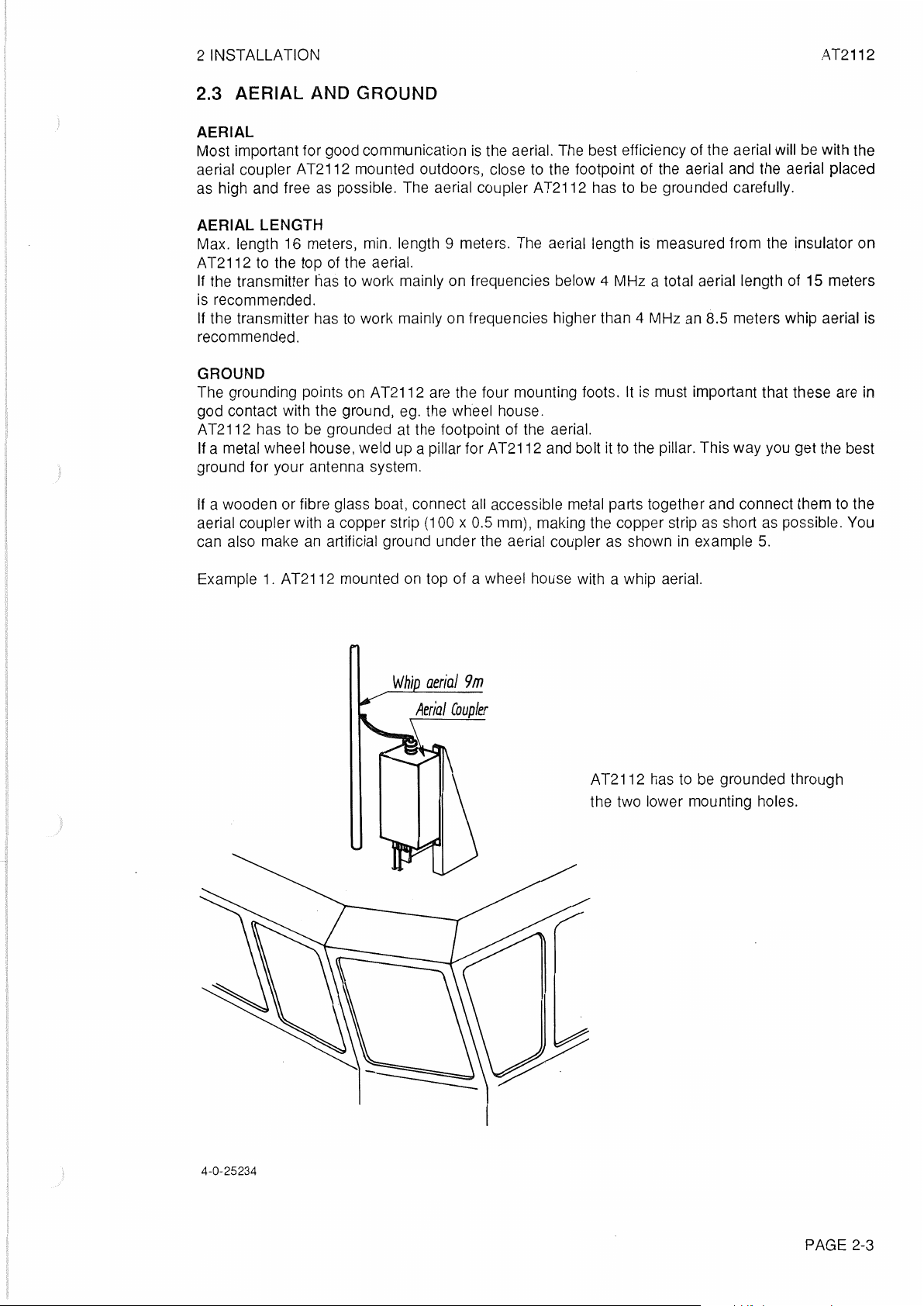
2.3 AERIAL AND GROUND
AERIAL
Most important for good communication
aerial coupler AT2112 mounted outdoors, close to the footpoint of the aerial and the aerial placed
as
high and free
AERIAL LENGTH
Max. length
AT2112 to the top
lf the transmitter tias to work mainly on frequencies below
is recommended.
lf the transmitter has
recommended.
GROUND
The grounding points
god contact with the ground,
AT2112 has to
lf a metal wheel house, weid up a pillar for AT2112 and bolt it
ground for your antenna system.
as
possible. The aerial coupler AT2112 has to
16
meters, min. length 9 meters. The aerial length
of
the aerial.
to
work mainly on frequencies higher than 4 MHz
on
AT2112 are the four mounting foots. lt
eg.
be
grounded at the footpoint of the aerial.
is
the aerial. The best efficiency of the aerial will
the wheel house.
be
with the
be
grounded carefully.
is
measured from the insulator on
4 MHz a total aerial length of 15 meters
an
8.5 meters whip aerial is
is
must important that these are
to
the pillar. This way you get the best
in
lf a wooden or fibre glass boat, connect
aerial coupler with a copper strip
an
can also make
Example
1.
artificial ground under the aerial coupler
AT2112 mounted
(100 x 0.5 mm), making the copper strip as short
on
top of a wheel house with a whip aerial.
Whip
aerial
all
accessible metal parts together and connect them to the
as
possible. You
as
shown in example
5.
9m
AT2112 has to
the two lower mounting holes.
be
grounded through
4-0-25234
PAGE 2-3
Page 8

2 INSTALLATION
AT2112
Example
lnsu/afor
Strain
2.
AT2112 mounted on top of a wheel house with wire aerial.
eg.
H23
rei/;ef
4-0-25235
AT 2112 has
tobe
grounded to the mast
if
a
meta! mast.
lf the mast
is
higher than 8 meters, then the
coax cable works as ground and acceptable
performance will
be
obtained.
lf the mast is less than 8 meters, then a copper strip (100 x 0.5 mm) has to connected from
AT2112 to ground.
Example
3.
AT2112 mounted on top
Aerial
C.Oup/er
h.
or
a mast.
PAGE 2-4
Page 9

2 INSTALLATION
AT2112
Example
4.
AT2112 mounted on a sailing ship.
lnsu/afor
Slrain
reilief
eg.
Wire
H23
lnsulafor
aeria.I
ef).
Aerial
cou
/er
H23
4-0-25237
AT2112 has to
be
grounded to the metal handrail or other metal parts.
PAGE 2-5
Page 10

2 INSTALLATION
5.
Example
AT2112 mounted on top of building.
Top
co.paci
cmck/ing
9 m
whip
Aerial
coup/er
to
the
mela/
lance
to
noice
(Rr:ceiving)
aerial
Hain
musf
plaJe.
ovoid
fransmission
be
grounded
AT2112
direc.tion
----~
Heia/
plale
fasfened
effedive~
fo
lhe
roof
Min.
16
roof
and
connecf
Cu.
slrips
cu.sfn°M
ef
feclivel!J
ed
to
lhe
fo
be
min
fasfened
fflelal
lo
declrical
plat.!.
50(
1
mm.
fhe
4-0-25239
PAGE 2-6
Page 11

AT2112
3
3.1
3.2
3.3
3.4
3.5
SERVICE
MAINTENANCE
ALIGNMENT INSTRUCTIONS
PROPOSAL FOR NECESSARY MEASURING INSTRUMENTS
TROUBLE SHOOTING
FUNCTION
CHECK
3-1
3-1
3-1
3-1
3-1
3-1
Page 12

AT2112
3 SERVICE
3.1
MAINTENANCE
PREVENTIVE MAINTENANCE
lf the HF SSB system has been installed properly the maintenance can, dependent on the
environments and working hours,
months. A complete performance check
CHECK.
lnspection of the antenna, cables, and plugs for mechanical defects, salt deposits, corrosion, and
any foreign bodies shall
Along with each
the test department of the factory, are listed. lf the control mesurings made in the service workshop
should not show the same values
specified
in
~F
the parts concerning the units
be
SSB system test sheets are delivered
done
be
reduced to a performance check at inteNals, not exceeding 12
is
enclosed
at
regular intervals not exceeding 12 months.
as
those listed in the test sheet, the set must be adjusted as
in
question.
in
this manual, chapter 3.5. PERFORMANCE
in
which all the measurements made in
3.2 ALIGNMENT INSTRUCTIONS
INTRODUCTION
in
The measuring values indicated
DIAGRAMS are typical values and
conformity with the below list:
chapter
as
indicated it will be necessary
5.
CIRCUIT DESCRIPTION AND SCHEMATIC
to
use instruments in absolute
3.3 PROPOSAL
Tone Generator type PM5107
Electronic Multimeter type PM2505
RF
Directional Wattmeter model
Oscilloscope type PM321
Dummy load 50 ohm/600W
Power supply 21-32V,
FOR
NECESSARY MEASURING INSTRUMENTS
PHILIPS
PHILIPS
43
BIRD
PHILIPS
50A ( 600W transmitter)
1
OOA
(1200W transmitter)
3.4 TROUBLE SHOOTING
in
Trouble shouting
looking into the circuit, and spot the defective component. Only if
semiconductors that are defective, you have to make measurements.
3.4.1 CHECKS
To check the relays, AT2112 must
Select serve programme SP-30-0 to SP-30-9 and SP-31-0 to SP-31-4, please see part
3.8.2. The service programme will enable you to activate each relay
see if it works.
a high power circuit where high voltage are preset, can normally be done by
it
is
one of the relays
OF
RELAYS
be
connected to the transmitter.
in
the aerial coupler,
or
1 paragraph
so
you can
3.4.2 CHECK
Select service programme SP-32-1 see part 1 paragraph 3.8.2, and check that the tune motor are
running with low speed.
Select SP-32_2, and check that the tune motor are running full speed.
Select SP-32-0, and check that the tune motor stops.
OF
THE TUNE MOTOR.
PAGE
3-1
Page 13

3 SERVICE AT2112
3.4.3 CHECK OF THE-180° PULSE CIRCUIT.
Select SP-32-1 and connect a oscilloscope to
reference), and check that
it
goes high once every turn of the tune motor.
P3
on
the aerial detector module
3.5 FUNCTION CHECK
To perform a function check,
to a suitable aerial. Then you must perform the function check described
it
is necessary to have a complete station, and
(1)
(chassis as
it
must
be
connected
in
part 1 paragraph 3.7.
PAGE 3-2
Page 14

AT2112
4
4.1
MECHANICAL ASSEMBLING / DISASSEMBLING AND UNITS
LOCATION
4-1
4-1
Page 15

4 MECHANICAL DESCRIPTION
4.1
MECHANICAL ASSEMBLING/ DISASSEMBLING AND UNITS LOCATION
AT2112
RE1
AERIAL CURRENT
DETECTOR
501134
(1)
f RE12
PAGE
4-1
Page 16

5
AT2112
5.1
5.2
AERIAL CURRENT DETECTOR (MODULE
MAIN SCHEMATIC DIAGRAM AT2112
1)
PART NO. 626641
5-1
5-1
9509
Page 17

AT2112
5 CIRCUIT DESCRIPTION
5.1
AERIAL CURRENT DETECTOR (1)
This module contains there main circuits:
1.
Aerial current detector
2.
180° pulse circuit.
3.
RF
switching circuit.
AND
SCHEMATIC DIAGRAMS
5.1.1 AERIAL CURRENT DETECTOR
The current to the aerial
proportional to the aerial current. This voltage
processor.
is
feed trough TR2. On the secondary side of TR2 there will be a voltage
is
5.1.2 180° PULSE CIRCUIT
When the motor
transistor
For every turn the light from the light emitting diode
transistor of
determine when to change the relay settings.
is
is
running, current flows trough the light emitting diode
turned
OC1
on,
and thus 01 will be on, giving low level on
to turn oft, and thus 01 will be off, giving a high level
rectified by
is
cut oft mechanically, causing the detector
D2
and
P3.
C3,
and feed to the TX-
of
OC1, and the detector
at
P3.
This pulse
is
used to
5.1.3
Depending
activated
1
RF
SWITCHING CIRCUIT.
on
the mode (refer to 5.2)
in
accordance with the table below.
MODE
RECEIVE MODE
TRANSMIT straight trough
MODE
OPEN
AERIAL
GROUNDED
AERIAL
1
simplex F>4 Mhz oft
simplex F<4 Mhz
simplex, TX tuned
tuned
in
which the aerial coupler
RE1
II
oft
on
oft oft oft
on oft oft
on oft
Off
is
RE2
1
on
on
oft oft
oft
working the relays will be
RE3
1
oft
on
on
1
Off
PAGE
5-1
Page 18

5 CIRCUIT DESCRIPTION AND SCHEMATIC DIAGRAMS
COMPONENT LOCATION AERIAL CURRENT DETECTOR MODULE 1
AT2112
View from component side with upper side tracks.
•
0
01
6
(j)
(j)
"'
~
......
0
.__
t-
(j)
(j)
(j)
"'
~
0
View from component side with lower side tracks.
PAGE 5-2
Page 19

9
lln8t:ll8
TVIH3'1
NOlldlt:l8S30
lN3HHno
H0103130
31naow
SltNt:l8\flO 811\fVBHOS ON\f
~
8-9
38\fd
Page 20

S
LlnOCJIO
ONV
NOl..LdlCIOS30
OLLVV'J3HOS
SVWC18VIO
p-g
38\fd
Page 21

5 CIRCUIT DESCRIPTION AND SCHEMATIC DIAGRAMS
5.2 MAIN SCHEMATIC DIAGRAM AT2112
AT2112
The aerial coupler
The aerial coupler can be
1.
Receive mode.
2.
Transmit mode.
AT2112
in
is controlled from the TX - processor
two different modes:
in
the transmitter.
5.2.1 RECEIVE MODE.
In this mode there are two different settings, one is simplex the other is semiduplex.
5.2.1.1 SEMIDUPLEX MODE AND THE FREQUENCY HIGHER THAN 4 MHZ.
The signal
board
5.2.1.2 SIMPLEX MODE AND THE FREQ. LOWER THAN OR
In this mode
TR1
transmitter.
TR1
gives the receiver a improved sensitivity on short aerials.
is
feed from the aerial trough RE12-RE2-RE3 and
in
the transmitter.
RE2·
and RE3 are activated. The signal from the aerial
(module 1) then further through RE3 -
is
transforming the high aerial impedance down to the lower impedance of the receiver. This
RE1
to the receiver via the connection board
RE1
to the receiver via the connection
EQUAL
is
feed trough RE12 -RE2 to
TO 4 MHZ.
in
the
5.2.1.3 SIMPLEX MODE. RECEIVE FREQUENCY EQUAL TO TRANSMIT FREQ.
In this mode, is the receiver using the tuning. which has been done by the transmitter. This will only
take place after the transmitter has performed a tuning. This gives a perfect match of the aerial
impedance
dB.
to
the receiver input impedance, this will improve the receiver sensitivity by approx. 1 O
5.2.2 TRANSMIT MODE
Here there are two different modes:
1.
Straight trough
2.
Tuning.
5.2.2.1 STRAiGHT TROUGH MODE.
This mode
the signal from the transmitter
when the aerial impedance is 50 ohms.
is
always selected
as
first choice by the TX-processor in the transmitter. In this mode
is
feed trough
RE1
-RE3-RE4-RE2 to the aerial. This mode
is
used
5.2.2.2 TUNING MODE.
This mode
controlled by the TX-processor, please refer also to PART
RE1
to
TR1
tuning circuit will tune.
is
selected if the aerial impedance
and RE12 will always be activated
and the impedance will
be
transformed to 12.5 ohm, this is the impedance for which the
is
different from 50 ohm. The tuning sequence is
in
tune mode. The signal from the transmitter will be feed
1 paragraph 3.5.3 tuning the AT2112.
PAGE 5-5
Page 22

811VVBH8S ONV NOLldlCJ8S30 .lln8CJl8 S
SV\JVCJ8VIO
9-S
38Vd
Page 23

w
~
;;
0
CO
..._
0
'tj"
{!)
{!)
(\J
0
~
5 CIRCUIT DESCRIPTION AND SCHEMATIC DIAGRAMS
MAIN SCHEMATIC DIAGRAM AT2112
Pl
POWER
IN
TO
STS
ON
CONNECTION
BOARD
PIN
1 Contro 1
PIN
2 Contro 1
PIN
3 Contro 1
PIN
4 Contro 1
PIN
5 Contro 1
6 Contro 1
PIN
Contro 1
PIN
7
Contro 1
PIN
B
Contro 1
PIN
9
Contro 1
PIN
10
Contro 1
PIN
11
PIN
12
Contro 1
RXITX
PIN
13
PIN
14
RX<4MHZ
PIN
15
Motor
AEllBIJl
PIN
16
Pulse
~
TRl
UJ
TL297
:
•i
1
--'--
~+--~~~~~~--
Lo;---
~
~:
1
·-·-·-•
. .. . . · · 1
23-50uH
L1
~
RE2
10-34uH
L2J
~
iT
L_,
__
a
Cl
n
T
20~1-
._
_____
~
3 3 3 3 1 3 3 3
_
- - _ l
RE3
~
m
RE4
C2
••
II
l00p
1crI1
~:
~
m
RE!l
::g
m
L-er L-er L-er L-er L-er
U
In
~.Gctr-<nl~r--..,I:tl.ctlr--~Lrrir--
RES : ..,
1
1
1
1
l
1
1
1
r~~~~--~~~~~~~~~~~~~
I
l
1
1
1
1
: -
1 -
1 t
1
1
1 E I
1 L
'--------------------------------
E:i
m
RE7
uin
T
...
i:g
~
REB
u"'
T"'
~
m
RE9
u"'
r-
~
~
c3
RE10
u"'
T"'
::::
~
REl
c3
------------------
1
n--:j
1
~r11
1
~
~
fEl
-
S-o.
JI
R;12
rrrl37?
R7
680R
-=-
t
______________________________
RE!
f
_i%
ao:r
·I
'I
·f
J
·f
RE2~--~
_,
':'.'1--v
~
TRI
b~
Tl526
f l
~
'"'T
~
RE3
t:l-:i_
~
1K0
,____.._------~
~
~
-.::
Cl
u3
~11
R9
i
~
"I
1
D~--.--
-=-
1
J
\II
f
::-
RS
~1~
~3
~t!
--'--
-II-
-=-
471ln
"''16
ao:_
OCI
TCST
1103
AT2112
0
Aerial
Current
Detectar
Cl>
4-l-26641D
112112[
PAGE 5-7
Page 24

9
SlSll
~-9
Page 25

PARTS LISTS
6
BASE
UNIT
AT2112
ECI
A/S
AT2112
702112
POSITION
VARIOUS
VARIOUS
-1
BL1
C1
C2
C3
C4
C5
C6
C7
C8
J1
L1+L2
L3
L4
M01
P1
R1
RE1
RE2
RE3
RE4
RES
RE6
RE7
RE8
RE9
RE10
RE11
RE12
TR1
DESCRIPTION
GABLE
AT2112
AERIAL
CURRENT
FAN
24VDC
CAPACITOR
CAPACITOR
CAPACITOR
STAK
STAK
CAPACITOR
CAPACITOR
CAPACITOR
RECEPTACLE
VARIOMETER
VARIOMETER
VARIOMETER
MOTOR
PLUG
RESISTOR
RELAY
RELA Y ORF1503
RELAY
RELAY
RELAYORF1503
RELAY
RELAY
RELAY
RELAY
RELAY
RELAY
RELAY
TRANSFORMER
CERAMIC
CERAMIC
CERAMIC
CAPACITOR
CAPACITOR
CERAMIC
CERAMIC
CERAMIC
(FEMALE)
1AT1500
II
AT1500
III A T1500
W.
GEARBOX
HIGH
DET.MODULE
850pF
450pF
VOLTAGE
AT2112
80x80mm
200i;f
20°b
1
OOpF
20%
30pF
20%
AT150x
AT150x
220QF
20°~
1
OOpF
20%
50pF
20%
2
POLE
C1065
10MOHM
ORF1501
ORF1501
ORF1501
ORF1501
ORF1501
ORF1501
ORF1501
ORF1501
ORF1501
ORF1502
TL297
N470
N33
N33
N470
N33
N33
10%
5kVDC
5kVDC
5kVDC
5kVDC
5kVDC
5kVDC
10kVDC
MANUFACTOR
ECI
A/S
PADRE
ECI
A/S
ELINA
FAN
LCC
LCC
LCC
ECI
A/S
ECI
A/S
LCC
LCC
LCC
AMP
ECI
A/S
ECI
ALS
ECI
A/S
MAXON
ECI
A/S
PHILIPS
ECI
ALS
ECI
A/S
ECI
A/S
ECI
A/S
ECI
A/S
ECI
ALS
ECI
A/S
ECI
A/S
ECI
A/S
ECI
A/S
ECI
A/S
ECI
A/S
ECI
A/S
TYPE
0-0-27413
Nr:30
04x125mm
5-0-26641
HDF
8025L-24MB
WA04T00201
WA04H00101
WA03H00300M
STAKKOND.1
STAKKOND. 2 450pF
WA04T00221
WA04H00101
WA03H00500M
0-826371-2
VARIOMETER
VARIOMETER
VARIOMETER
SP
SPEC.:
KEJSERSTIK
2322
24413106
ORF1501
ORF1503
ORF1501
ORF1501
ORF1503
ORF1501
ORF1501
ORF1501
ORF1501
ORF1501
ORF1501
ORF1502
6-0-22611
B=4mm
C /
4-0-26641
M
M
850pF
M
M
1
2
3
C1065
SLUTTEREUE
SLUTTER.m/HVILEK.
SLUTTEREUE
SLUTTEREUE
SLUTTER.m/HVILEK.
SLUTTEREUE
SLUTTEREUE
SLUTTEREUE
SLUTTEREUE
SLUTTEREUE
SLUTTEREUE
SKIFTEREUE
PART
NO.
527413
D
66.526
626641
60.050
18.065
18.050
18.015
707779
707780
18.070
18.050
18.020
78.122
707756
707757
707758
60.010
707773
06.050
705051
705068
705051
705051
705068
705051
705051
705051
705051
705051
705051
705061
400297
AERIAL
POSITION
CH
C2-1
C3-1
DH
D2-1
OC1-1
P13-1
Q1-1
RH
R2-1
R3-1
R4-1
R5-1
R6-1
R7-1
R8-1
R9-1
REH
RE2-1
RE3-1
TRH
TR2-1
CURRENT
DESCRIPTION
CAPACITOR
CAPACITOR
CAPACITOR
DIODE
DIODE
PHOTOINTERRUPTER
PLUG
TRANSISTOR
RESISTOR
RESISTOR
RESISTOR
RESISTOR
RESISTOR
RESISTOR
RESISTOR
RESISTOR
RESISTOR
RELAY
RELAY
RELAY
TRANS
TRANSFORMER
DET.MODULE
CERAMIC
CERAMIC
MKT
HIGH
SPEED
HIGH
SPEED
AF
MF
MF
PMF
MF
MF
MF
MF
FORMER
AT2112
1
OnF
-20/+80%
1
OnF
-20/+80%
470nF
10%
1N4448
1N4448
2
POLES
NPN
BC639
47
OHM5%
47
OHM
5°~
1
kO
OHM
5%
1k0
OHM
470
680
680
680
TL526
TL310
5%
OHM
5%
12k
OHM
5%
OHM
5°~
OHM
5%
OHM
5%
12VDC
1SH.
12VDC 1 SH.
12VDC 1 SH.
63V
T0-92
7W
7W
0.33W
0.33W
2W
0.33W
0.4W
0.4W
0.4W
8A.
8A.
8A.
CL2
CL2
50VDC
50VDC
ECI
A/S
MANUFACTOR
KCK
KCK
ERO*
PHILIPS
PHILIPS
TELEFUNKEN
AMP
PHILIPS
PHILIPS
PHILIPS
PHILIPS
PHILIPS
PHILIPS
PHILIPS
PHILIPS
PHILIPS
PHILIPS
SCHRACK
SCHRACK
SCHRACK
ECI
A/S
BB
5-0-26641
TYPE
RT-HE70
SK
RT-HE70
SK
MKT
1818-447
1N4448
1N4448
TCST
1103
0-826375-2
BC639
2322
329
07
2322
329
07
2322
187
73102
2322
187
73102
2322
194
13471
2322
187
73123
2322
181
53681
2322
181
53681
2322
181
53681
RYS12012
RYS12012
RY S 12
012
6-0-258678
6-0-23162E
C /
4·0·26641 D 626641
PART
YF
103
Z
YF
103
Z
/065
479
479
NO.
15.170
15.170
11.185
25.147
25.147
32.521
78.102
28.120
05.866
05.866
02.472
02.472
04.191
02.498
01.195
01.195
01.195
21.031
21.031
21.031
400526
400310
9507
PAGE
6-1
 Loading...