

Page 1
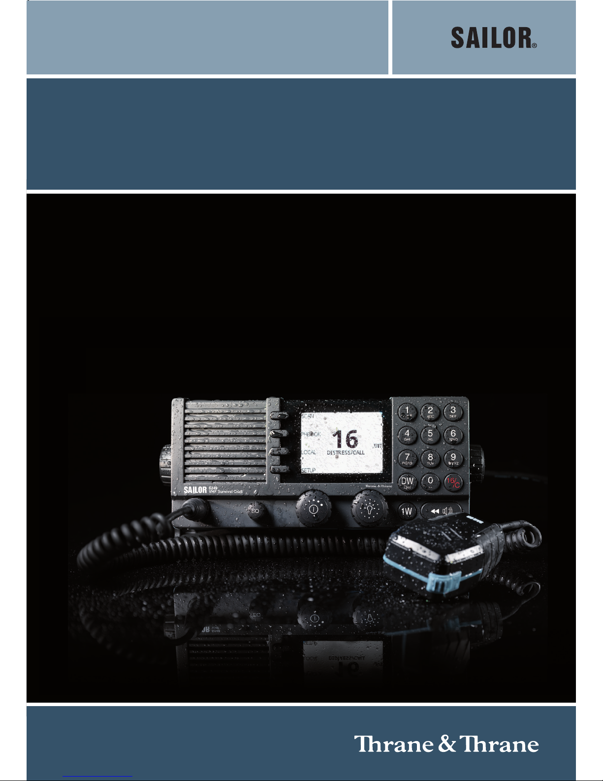
USER MANUAL
SAILOR 6249 VHF Survival Craft
Page 2

Page 3

SAILOR 6249 VHF Survival Craft
User manual
Document number: 98-133865-C
Release date: November 29, 2012
Page 4

Disclaimer
Any responsibility or liability for loss or damage in connection with the use of this
product and the accompanying documentation is disclaimed by Thrane & Thrane. The
information in this manual is provided for information purposes only, is subject to
change without notice and may contain errors or inaccuracies.
Manuals issued by Thrane & Thrane are periodically revised and updated. Anyone
relying on this information should acquire the most current version e.g. from thrane.com
or from the distributor.
Thrane & Thrane is not responsible for the content or accuracy of any translations or
reproductions, in whole or in part, of this manual from any other source.
Copyright
© 2012 Thrane & Thrane A/S. All rights reserved.
Trademark Acknowledgements
• Thrane & Thrane is a registered trademark of Thrane & Thrane A/S in the European
Union and the United States.
• SAILOR is a registered trademarks of Thrane & Thrane A/S.
• Other product and company names mentioned in this manual may be trademarks or
trade names of their respective owners.
GPL notification
The software included in this product contains copyrighted software that is licensed
under the GPL/LGPL. The verbatim licenses can be found online at:
http://www.gnu.org/licenses/old-licenses/gpl-2.0.html
http://www.gnu.org/licenses/old-licenses/lgpl-2.1.html
You may obtain the complete corresponding source code from us for a period of three
years after our last shipment of this product, which will be no earlier than December 31,
2015, by sending a money order or check for DKK 50 to:
SW Technology/GPL Compliance,
Thrane & Thrane A/S,
Lundtoftegaardsvej 93D
2800 Lyngby
DENMARK
Page 5

Please write "source for product SAILOR 6249 VHF Survival Craft" in the memo line of
your payment.
You may also find a copy of the source at http://www.thrane.com/foss.
This offer is valid to anyone in receipt of this information.
Warranties
Any attempt to install or execute software not supplied by Thrane & Thrane on this
device will result in the warranty being void. Any attempt to modify the software on this
device in a way not specified by Thrane & Thrane will result in the warranty being void.
Page 6

iv
Safety warning 1
The following general safety precautions must be observed during all
phases of operation, service and repair of this equipment. Failure to comply
with these precautions or with specific warnings elsewhere in this manual
violates safety standards of design, manufacture and intended use of the
equipment. Thrane & Thrane assumes no liability for the customer's failure
to comply with these requirements.
Ground the equipment
To minimise shock hazard, the SAILOR 6249 VHF Survival Craft unit must be
connected to an electrical ground and the cable instructions must be
followed.
RF exposure hazards and instructions
Your Thrane & Thrane radio set generates electromagnetic RF (radio
frequency) energy when transmitting. To ensure that you and those around
you are not exposed to excessive amounts of energy and thus to avoid health
hazards from excessive exposure to RF energy, all persons must be at least
200 cm away from the antenna when the radio is transmitting.
Warranty limitation
IMPORTANT - The radio is a sealed waterproof unit (classified IPX8). To
create and maintain its waterproof integrity it was assembled in a controlled
environment using special equipment. The radio is not a user maintainable
unit, and under no circumstances should the unit be opened except by
authorized personnel. Unauthorized opening of the unit will invalidate the
warranty.
Installation and service
Installation and general service must be done by skilled service personnel.
Page 7

v
Compass safe distance
Minimum safety distance: 0.85 m from the SAILOR 6249 VHF Survival Craft.
Page 8

vi
Alerte de sécurité 2
Dangers liés à l'exposition aux fréquences radio et instructions
Conformément à la réglementation d'Industrie Canada, le présent radio
émetteur ne peut fonctionner qu'avec une antenne de type
omnidirectionnelle, demi-onde ou d'un gain maximal de 4 dB, approuvée
par Industrie Canada. Pour éviter les risques pour la santé dûs à une
exposition excessive aux champs de fréquences radio, une distance
minimale de 200 cm est nécessaire entre l'utilisateur et le radio-émetteur.
Page 9
vii
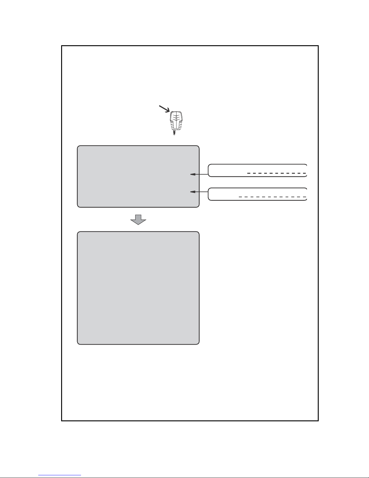
Emergency calls
MAYDAY
NAME of the VESSEL in distress
CALLSIGN or other IDENTIFICATION
POSITION
given as latitude and longitude
or
If latitude and longitude are not known
or if time is insuffi cient,
in relation to a known geographical location
NATURE of distress
Kind of ASSISTANCE required
Any other useful INFORMATION
MAYDAY-MAYDAY-MAYDAY
This is
NAME-NAME-NAME
CALLSIGN
or other IDENTIFICATION
Use the SPEAKER
MICROPHONE for voice calling
Make sure your VHF Radio is on CH16
SHIP‘s NAME:
CALLSIGN:
OWN ID
99-133789
Press Press
or
Page 10

viii
Preface 3
Radio for occupational use
The SAILOR 6249 VHF Survival Craft fulfils the requirements of the
Marine Equipment Directive 96/98/EC and the amending Directive
2010/68/EU and is intended for use in maritime environment.
SAILOR 6249 VHF Survival Craft is designed for occupational use
only and must be operated by licensed personnel only.
SAILOR 6249 VHF Survival Craft is not intended for use in an
uncontrolled environment by general public.
SAILOR 6249 VHF Survival Craft is designed for installation by a
skilled service person.
Page 11

ix
Training information 4
The SAILOR 6249 VHF Survival Craft is designed for occupational
use only and is also classified as such. It must be operated by
licensed personnel only. It must only be used in the course of
employment by individuals aware of both the hazards as well as
the way to minimize those hazards
The radio is thus NOT intended for use in an uncontrolled
environment by general public. The SAILOR 6249 VHF Survival
Craft complies with the FCC RF exposure limits for Occupational
Use Only. The radio also complies with the following guidelines
and standards regarding RF energy and electromagnetic energy
levels including the recommended levels for human exposure:
• FCC OET Bulletin 65 Supplement C, evaluating compliance with
FCC guidelines for human exposure to radio frequency
electromagnetic fields.
• American National Standards Institute (C95.1) IEEE standard for
safety levels with respect to human exposure to radio frequency
electromagnetic fields, 3 kHz to 300 GHz
• American National Standards Institute (C95.3) IEEE
recommended practice for the measurement of potentially
hazardous electromagnetic fields - RF and microwaves.
Below the RF exposure hazards and instructions in safe operation
of the radio within the FCC RF exposure limits established for it are
described.
Warning
Your Thrane & Thrane radio set generates electromagnetic RF
(radio frequency) energy when it is transmitting. To ensure that
you and those around you are not exposed to excessive amounts of
that energy (beyond FCC allowable limits for occupational use) and
thus to avoid health hazards from excessive exposure to RF
energy, FCC OET bulletin 65 establishes an Maximum Permissible
Exposure (MPE) radius of 200 cm for the maximum power of your
radio (25W selected) with an half wave omni-directional antenna
Page 12

x
having a maximum gain of 4 dB. This means all persons must be at
least 200 cm away from the antenna when the radio is
transmitting.
Installation
1. An omni-directional antenna with a maximum power gain of
4 dB must be mounted at least 400 cm above the highest deck
where people may be staying during radio transmissions. The
distance is to be measured vertically from the lowest point of
the antenna. This provides the minimum separation distance
which is in compliance with RF exposure requirements and is
based on the MPE radius of 200 cm plus the 200 cm height of
an adult.
2. On vessels that cannot fulfil requirements in item 1, the antenna
must be mounted so that its lowest point is at least 3 ft. (0.9m)
vertically above the heads of people on deck and all persons
must be outside the 200 cm MPE radius during radio
transmission.
• Always mount the antenna at least 200 cm from possible
human access.
• Never touch the antenna when transmitting
• Use only authorized T&T accessories.
3. If the antenna has to be placed in public areas or near people
with no awareness of the radio transmission, the antenna must
be placed at a distance not less than 200 cm from possible
human access.
Failure to observe any of these warnings may cause you or other
people to exceed FCC RF exposure limits or create other dangerous
conditions.
Page 13

xi
Manual overview
This manual has the following chapters and appendices:
• Introduction contains a description of the VHF radio.
• Operation explains how to make and receive voice calls over
VHF, including how to use and set-up scanning, watch and
replay.
• Service & maintenance contains support information including
lists of accessories and a troubleshooting guide.
• Appendix with Technical pecifications and Maritime channels.
Related documents
Important
All installation information and instructions are not covered in this
manual. Please download the SAILOR 6249 VHF Survival Craft
Installation manual at http://extranet.thrane.com/.
In the installation manual you can read how to mount the VHF radio
and how to connect accessories and external equipment, including
detailed system configuration examples with cable specifications.
Title and description Document number
SAILOR 6249 VHF Survival Craft,
Installation guide
98-133943
SAILOR 6249 VHF Survival Craft,
Installation manual (download only)
98-133942
Emergency call sheet 98-133795
Page 14

xii
Page 15

xiii
Table of Contents
Chapter 1 Introduction
VHF radio ........................................................................... 1
Accessories available .........................................................4
Chapter 2 Operation
Overview ............................................................................7
General use and navigation .............................................. 8
VHF radio communication ................................................. 11
Watch ............................................................................... 14
Scan ................................................................................. 15
Phone book ...................................................................... 16
Replay function ................................................................ 18
Setup ............................................................................... 18
Chapter 3 Service & maintenance
Contact for support ...........................................................25
Maintenance ....................................................................25
Troubleshooting guide .....................................................26
Warranty and returning units for repair ............................29
App. A Technical pecifications
Transceiver unit SAILOR 6249 VHF Survival Craft .............. 31
SAILOR 6090 Power Converter 24—12 V .............................33
App. B Maritime channels
International channels (INT) ........................................35
Page 16

Table of Contents
xiv
Glossary .........................................................................................37
Index ........................................................................................ 39
Page 17
1
Chapter 1
11111
Introduction
Introduction 1
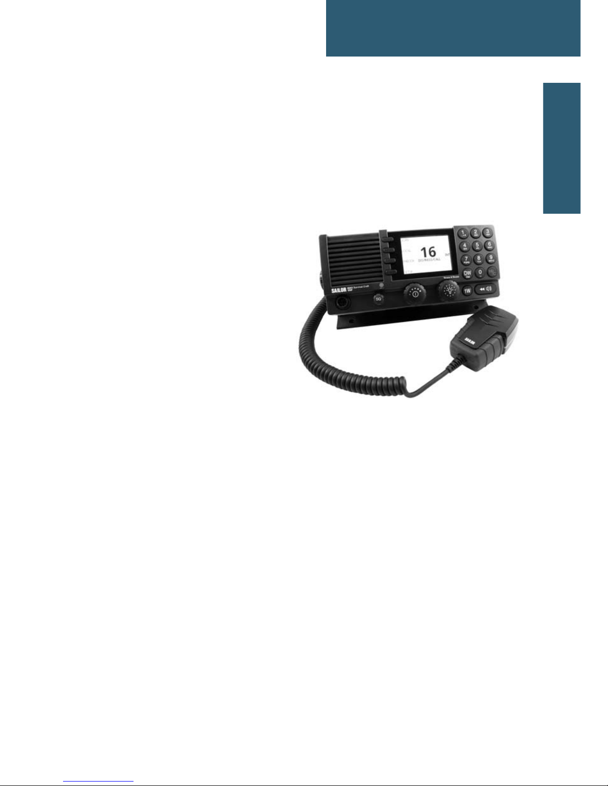
VHF radio
SAILOR 6249 VHF Survival
Craft is designed for use in
survival crafts. It is approved
to MED and waterproof to the
IPx8 and IPx6 standard. As
part of the required safety
equipment, use the SAILOR
6249 VHF Survival Craft in an
emergency situation. However
the best way to guarantee
functionality in an emergency
situation, is to use the radio in
daily communication on board.
The VHF radio is a simplex VHF radio. It is designed with an easy-to-use
menu-driven setup. You use the softkeys and the keypad to enter the desired
functions, you browse and select a setting using the right selection knob. The
large display can be customized for optimum readability and visibility both day
and night with several color themes.
The VHF radio can replay the last 240 s of received voice messages. This is a
useful feature to minimize misunderstandings and to record messages when
the radio is unattended.
The Ethernet interface enables the VHF radio to be connected to ThraneLINK
for service updates.
For a list of accessories available for the VHF radio see Accessories available
on page 4 and check with your nearest distributor.
Page 18
Chapter 1: Introduction
2 VHF radio
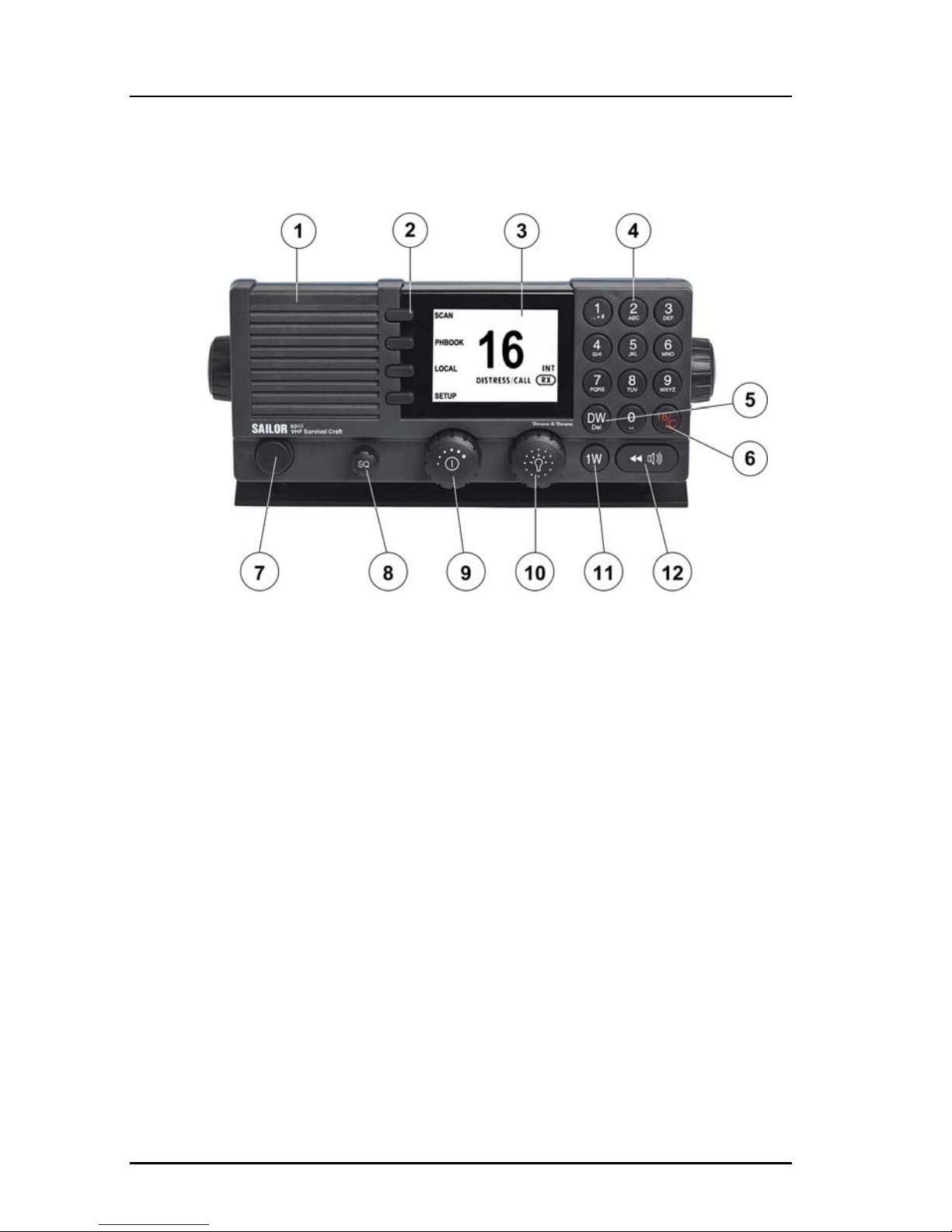
Controls on the front plate
1. Loudspeaker.
2. Four soft keys with function title in the display.
3. Large display.
4. Keys 0 to 9 to enter numbers or text.
5. DW button to toggle the watch function.
6. 16/C quick selection key for channel 16 and the programmed call channel.
7. Handmicrophone. If not used, put the cap from the ACC connector on the
front connector to prevent water ingress.
8. Squelch control to mute background noise.
9. Volume knob with key-press function for volume control and power on/off.
10. Selector and dim knob with key-press function for general operation,
display color selection and dimming.
11. 1W button to toggle between high and low power.
12. Replay button to play back up to 240 s voice message.
Page 19
Chapter 1: Introduction
VHF radio 3
11111
Introduction
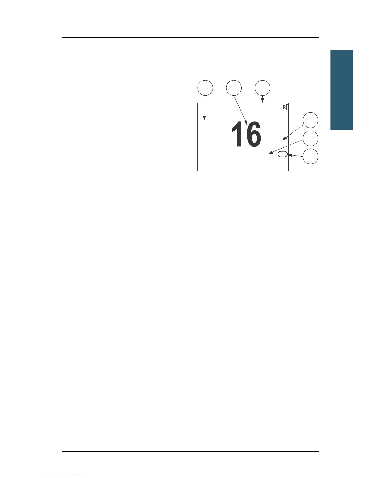
SAILOR 6249 VHF Survival Craft display
The picture shows the display after
start-up. The display holds various
fields of information, depending
on the currently selected
function.
1. Functions you can select with
the soft keys.
2. Current working channel.
3. System property icons with
information relevant for the currently selected functions.
4. Channel properties next to the currently selected VHF channel (if any).
5. Service line containing current temporary information relevant for the
current channel or function.
6. Current state: RX or TX.
For a detailed description of the information shown for each of the functions
available see the chapter Operation on page 7.
5
6
4
SCAN
PHBOOK
LOCAL
SETUP
INT
LOC LO
DISTRESS/CALL
RX
3
21
Page 20
Chapter 1: Introduction
4 Accessories available
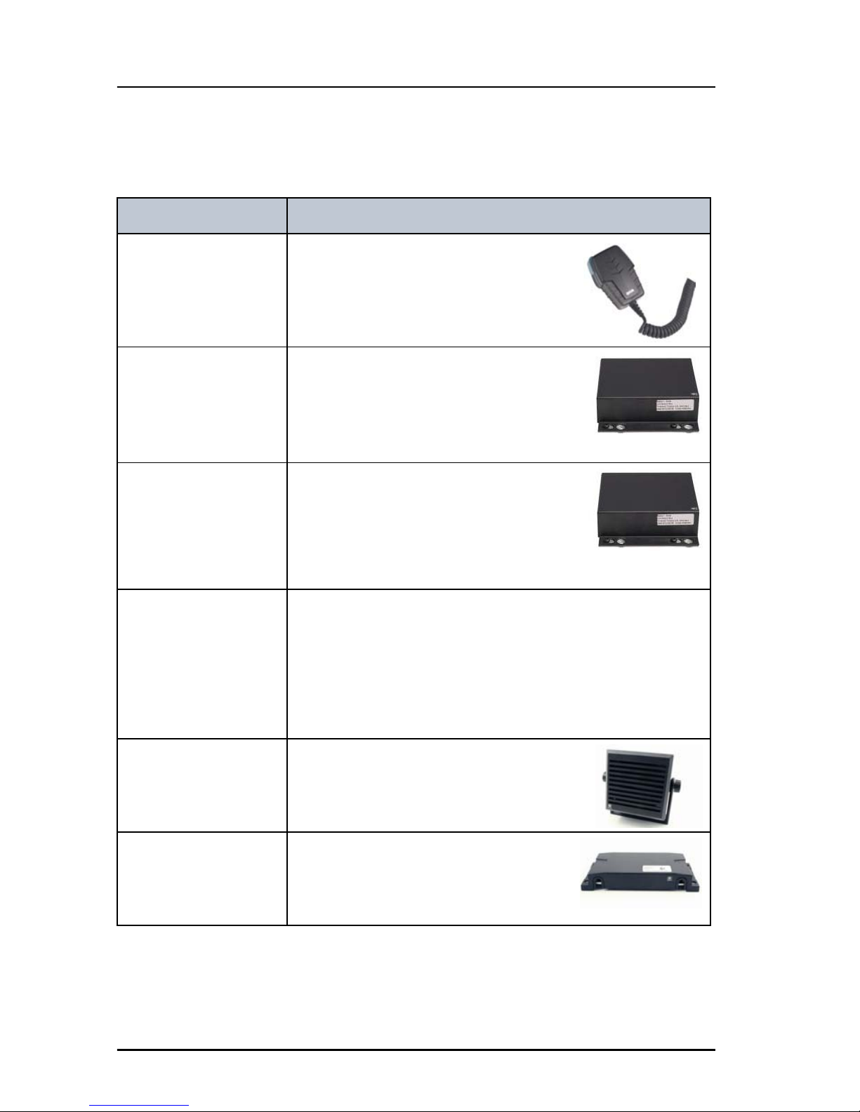
Accessories available
Accessory Description
SAILOR 6202 Hand
Microphone
You can use the SAILOR 6202 Hand
Microphone (waterproof to IPx6 and
IPx8) .
SAILOR 6207
Connection Box for
parallel Handsets
The SAILOR 6207 Connection Box for
parallel Handsets including Connection
Cable 406209-941 is used for easy
installation of several Hand
Microphones.
SAILOR 6208 Control
Unit Connection Box
SAILOR 6208 Control Unit Connection
Box including Connection Cable
406208-941 is used for easy installation
of external equipment and accessories:
• VDR
Connection cables 5m connection cable for bulkhead mount: Use this cable
in installations where the SAILOR 6202 Hand Microphone
is not connected directly to the SAILOR 6249 VHF Survival
Craft, but located in a different position (part number:
406204-940).
SAILOR 6270 External
Loudspeaker
If you need an additional external
loudspeaker you can connect a SAILOR
6270 External Loudspeaker. It provides
6 W output power.
SAILOR 6090 Power
Converter 24 V to
12 V DC
The SAILOR 6090 Power Converter is
used to provide 12 V DC for the SAILOR
6249 VHF Survival Craft from a 24 V DC
power source.
Page 21
Chapter 1: Introduction
Accessories available 5
11111
Introduction
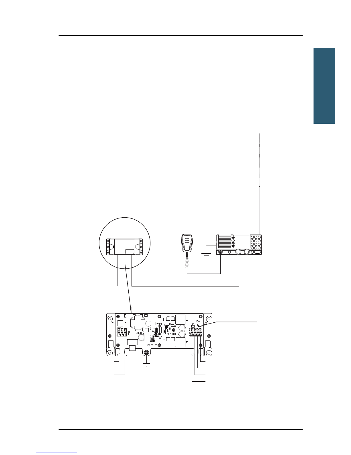
System configuration — example
The SAILOR 6249 VHF Survival Craft can be customized to suit your
installation. The following illustration is one example of a system. For further
configuration examples see the installation manual, Appendix B, System
configurations.
Figure 1-1: System configuration, example
VHF
SAILOR 6249
Hand Microphone
SAILOR 6202
Power Converter
SAILOR 6090
12V DC
Ground
12V DC
+Vout (Red)
-Vout (Blue)
Remote on/off
NC
Screen/Ground
-Vin
+Vin
24V DC
Remove jumper
for remote on/off
from VHF
Aerial
RX/TX
24V DC
Page 22

Chapter 1: Introduction
6 Accessories available
Page 23

7
Chapter 2
22222
Operation
Operation 2
Overview
In this chapter you find detailed instructions and guidelines for:
• General use and navigation
• VHF radio communication
• Watch
• Scan
• Phone book
• Replay function
• Setup
Note
Before using the VHF radio make sure that the VHF, power cable and other
external equipment are connected properly. For installation instructions
see the SAILOR 6249 VHF Survival Craft, Installation manual (download
only).
Page 24
Chapter 2: Operation
8 General use and navigation
General use and navigation
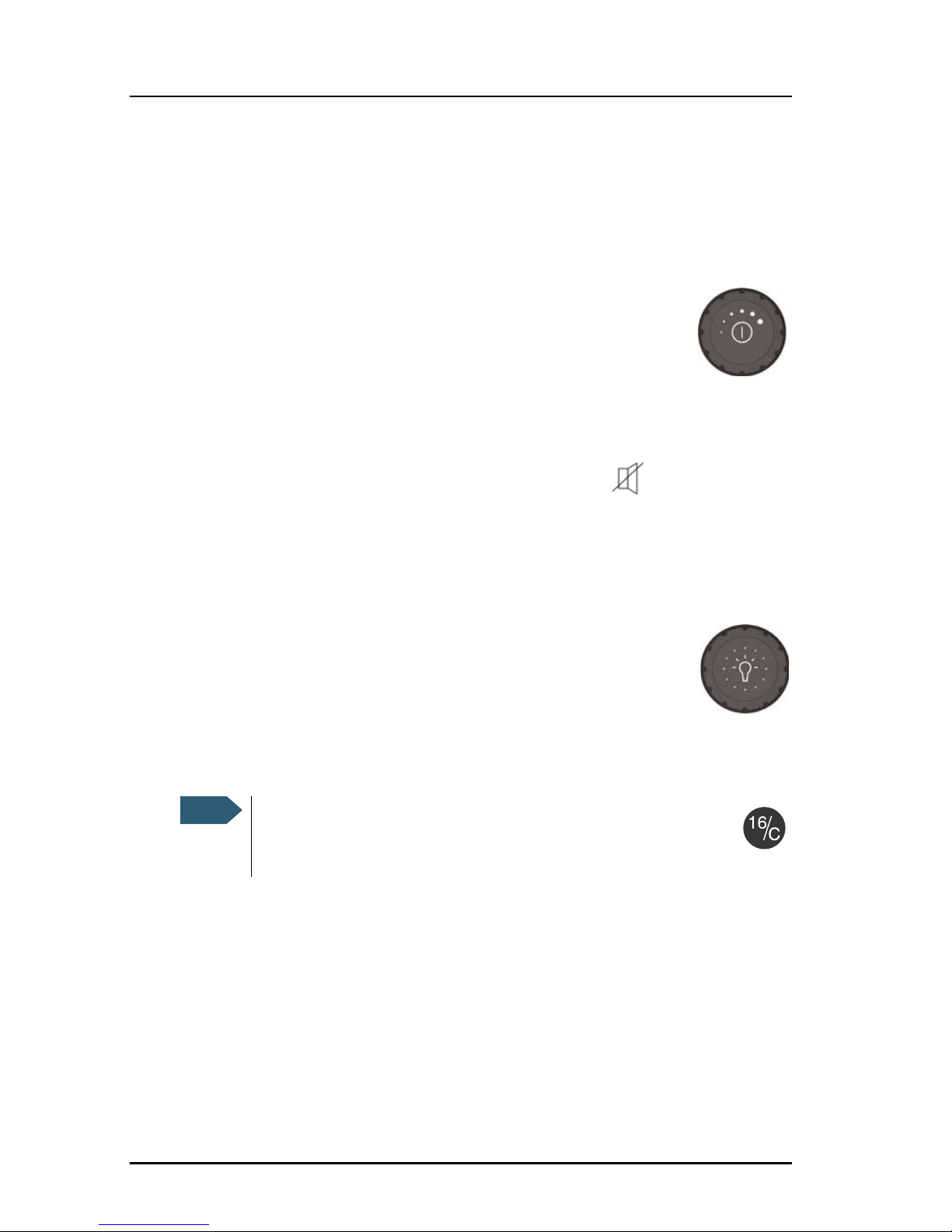
Power on and volume in speaker
The VHF radio has a dual-function on/off knob for power on/off
and volume control.
To power on the VHF radio press the on/off knob.
To power off the VHF radio, press and hold the on/off knob and
follow the instructions in the display.
To adjust the speaker volume, turn the volume knob (clockwise = louder,
counter clockwise = softer, until muted). When muted, is shown in the
display.
Working channel and changing settings
Use the selector knob to browse and select:
• To browse and select settings, turn the selector knob and
press for accept.
• To select a working channel use the selector knob or enter
the channel number using the keypad. You can change channels whenever
the channel designator is displayed.
Note
A single, short press on the 16/C key always brings you to
channel 16, the international calling and distress channel,
no matter what state the radio is in.
Page 25
Chapter 2: Operation
General use and navigation 9
22222
Operation
Speaker devices
The VHF radio can be equipped with the following speaker device:
• SAILOR 6202 Hand Microphone with PTT button.
See Controller setup on page 22 for controlling the connected speaker device.
Soft-key functions
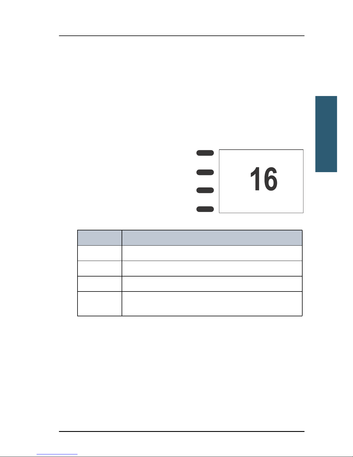
A number of functions of the SAILOR
6249 VHF Survival Craft are accessed
and set using the four soft keys to the
left of the display. The current function
of a soft key is shown in the display next
to the soft key.
The following soft-key functions are
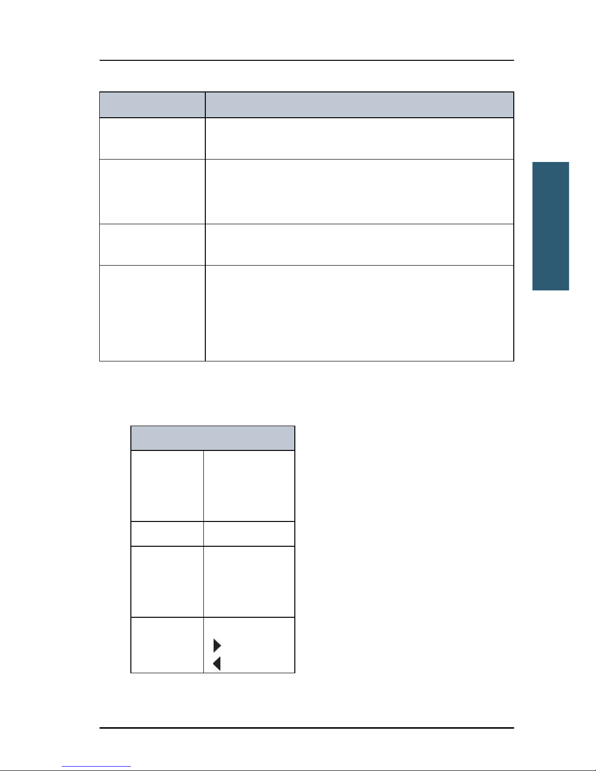
available from top-level standby:
Soft key Function
SCAN Scanning menu with start, stop and tag function
PHBOOK Phone book
LOCAL Local mode, 10 dB attenuation
SETUP Setup pages for Radio setup, Channel setup, Power Supply,
System setup and Controller setup.
SCAN
PHBOOK
LOCAL
SETUP
INT
DISTRESS/CALL
Page 26

Chapter 2: Operation
10 General use and navigation
Changing the display light, night view
Red text on black background is available for optimal night vision.
To dim the display backlight, e.g. to give comfortable night vision, press, hold
and turn the selector knob anti-clockwise. The display shows a brightness bar.
At the brightness value 45 the display changes to night view with red text on
black background.
To return to day vision press, hold and turn the
selector knob clockwise until the display
changes and it reaches the desired
brightness.
The radio has two colour themes: Black text on
a white background (default) or white text on
black background. To change the color theme
see System setup on page 22.
Adjusting the squelch level
With the Squelch control you can manually adjust and suppress noise
in order to optimize the quality of the received radio communication.
When hearing noise or an unwanted signal, turn the squelch button
clockwise until the speaker is muted.
SCAN
PHBOOK
LOCAL
SETUP
INT
DISTRESS/CALL
Alternative colour scheme
Page 27
Chapter 2: Operation
VHF radio communication 11
22222
Operation
VHF radio communication
Basic VHF operation
You can make VHF calls using the speaker device.
Quick guide to radio telephone calls
1. Press the PTT button on the speaker device. When the TX indicator
lights up in the display, the transmission is active.
2. To enable reception of a radio signal release the PTT button.
Receiving a radio telephone call on channel 16
When you hear your call name in the loudspeaker, proceed as follows:
1. The symbol RX shows that the radio is receiving on the channel displayed.
2. Lift the speaker device.
3. Press the PTT button. The symbol TX shows that the radio is transmitting on
the channel displayed.
4. Repeat the name of the station calling you and say: “This is [your ship’s
name]”.
5. Suggest a working channel other than 16 by saying: “Channel [suggested
channel number]”.
Note
A single, short press on the 16/C key always brings you to
channel 16, the international calling and distress channel,
no matter what state the radio is in.
Note
Press PTT only when you are talking. Always say “Over.” just before
releasing the PTT button.
One transmission is limited to 5 minutes duration.
Page 28

Chapter 2: Operation
12 VHF radio communication
6. Say: “Over.” and release the PTT button to allow the caller to confirm the
suggested new channel.
7. Switch to the new channel using the keypad or by turning the selector knob
to the agreed channel and begin your conversation. Press PTT only when
you are talking.
Making a radio telephone call on channel 16
To make a radio telephone call, proceed as follows:
1. Select channel 16.
2. Lift the speaker device.
3. Press the PTT button. The symbol TX shows that the VHF radio is
transmitting on the working channel displayed.
4. Say the name of the station you are calling three times.
5. Say: “This is [your ship’s name]”.
6. Say: “Over.” and release the PTT button to listen. The symbol RX shows
that the radio is receiving on the working channel displayed
7. When answered, agree upon a working channel other than 16.
8. Switch to the new channel by entering the channel number to the agreed
channel and begin your conversation.
Page 29
Chapter 2: Operation
VHF radio communication 13
22222
Operation
VHF channels
You can change channels whenever the channel designator is displayed. Enter
the channel using the keypad or turn the selector knob to browse through all
channels that are available in the selected channel table. Only valid channel
numbers are accepted. When browsing channels they appear in the display in
the following order:
• Primary channels
• Private channels (if any)
With a long press on the 16/C key the radio changes to the call
channel (channel 16 for the channel table INT, if no other channel is
programmed in Channel setup on page 21).
For more information on how to setup channels setup see Channel setup on
page 21. Contact your local dealer if you are interested in having private
channels.
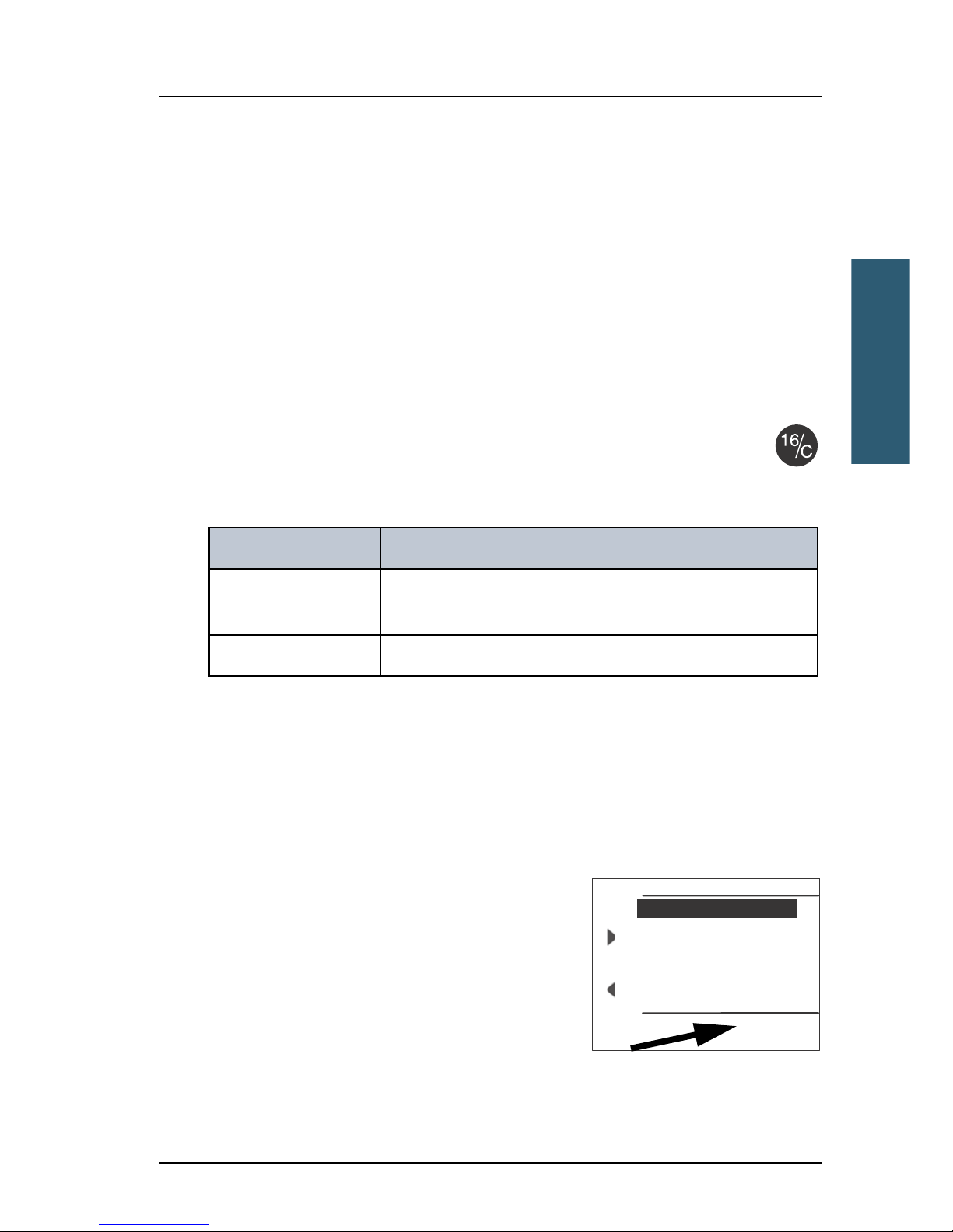
Channel information always available in the display
For some functions and for setup pages, the
channel and radio information has moved to
the bottom section of the display. You can
change channels whenever the channel
designator is displayed.
The channel number displayed in this section
always reflects the communication channel on
which the radio is tuned into for
VHF channel table Description
Primary channels
(no prefix)
For details see Maritime channels on page 35.
Private (PRIV) Up to 100 user-defined private channels.
EXIT CONTROLLER SETUP
10
Handset 1 vol: 80
Handset 2 vol: 80
Ext. speaker: FIX
Ext. Fixed vol: OFF
Wheel Lock: OFF
(Example)
Page 30
Chapter 2: Operation
14 Watch
communication. If PTT is pressed the radio transmits on the displayed
channel. If a signal is received, it is received on the displayed channel.
Reduced transmission power LO
Press the key 1W to toggle the transmit power between low (1 W, LO is
displayed) and high (25 W).
Local mode, 10 dB attenuation
Press the soft key LOCAL to add 10 dB attenuation.
Watch
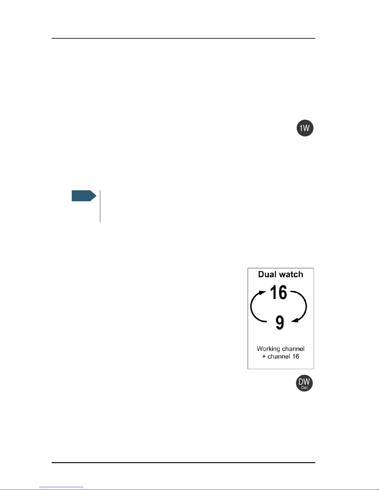
The SAILOR 6249 VHF Survival Craft radio has a dual
watch function. The working channel and channel 16
can be watched. You can select the working channel
in any watch mode by turning the selector knob. If
there is a signal in one of the watched channels, the
display shows the channel in which the signal is
received.
To start the watch function press the key DW. The
radio enters the watch mode and the text WATCH with the channel
numbers watched is shown below the current channel number.
To stop the watch function press the key DW again or PTT on the speaking
device.
Note
Local mode is automatically exited when selecting channel 16 by
pressing 16/C button. If you want to use attenuation on channel 16 or
a call channel, you must set it manually each time.
Page 31

Chapter 2: Operation
Scan 15
22222
Operation
Scan
The radio has a scanning function for tagged voice channels. Any available
voice channel, including weather and private channels, can be tagged and
added to the scanning sequence. As default the radio scans with priority
scanning of channel 16. If a signal is received while in any scanning mode,
only channel 16 continues to be watched.
If there is a signal in one of the scanned channels, the display shows the
channel in which the signal is received. If PTT is pressed while scanning, the
scanning stops, the radio is tuned into the displayed channel and transmission
starts immediately on the displayed working channel.
To start scanning press the soft key SCAN. The
SCAN menu is shown. Press START to start
scanning. To leave the SCAN menu, but not
the scanning procedure, press EXIT.
To stop scanning press STOP, QUIT if not in the
SCAN menu, or press PTT on the speaking
device.
To tag a channel for scanning turn the selector
knob until the wanted channel is in the
display. Then press the soft key TAG. The
display shows the channel number and the
word TAG at the right side of the display.
To remove a channel from the scanning
sequence turn the selector knob until the
tagged channel is displayed. Then press the soft key TAG to remove the tag.
To see only tagged channels press the soft key FILTER and turn the selector
knob. Press the soft key FILTER to leave the FILTER function. For details how to
set up the scanning function see Radio setup on page 19.
Note
The displayed working channel is temporarily included in the
scanning list (although no TAG icon is shown).
EXIT
START
TAG
FILTER
INT
INTERSHIP/PORT
EXIT
STOP
TAG
FILTER
INT
SCANNING[16]
Page 32
Chapter 2: Operation
16 Phone book
Phone book
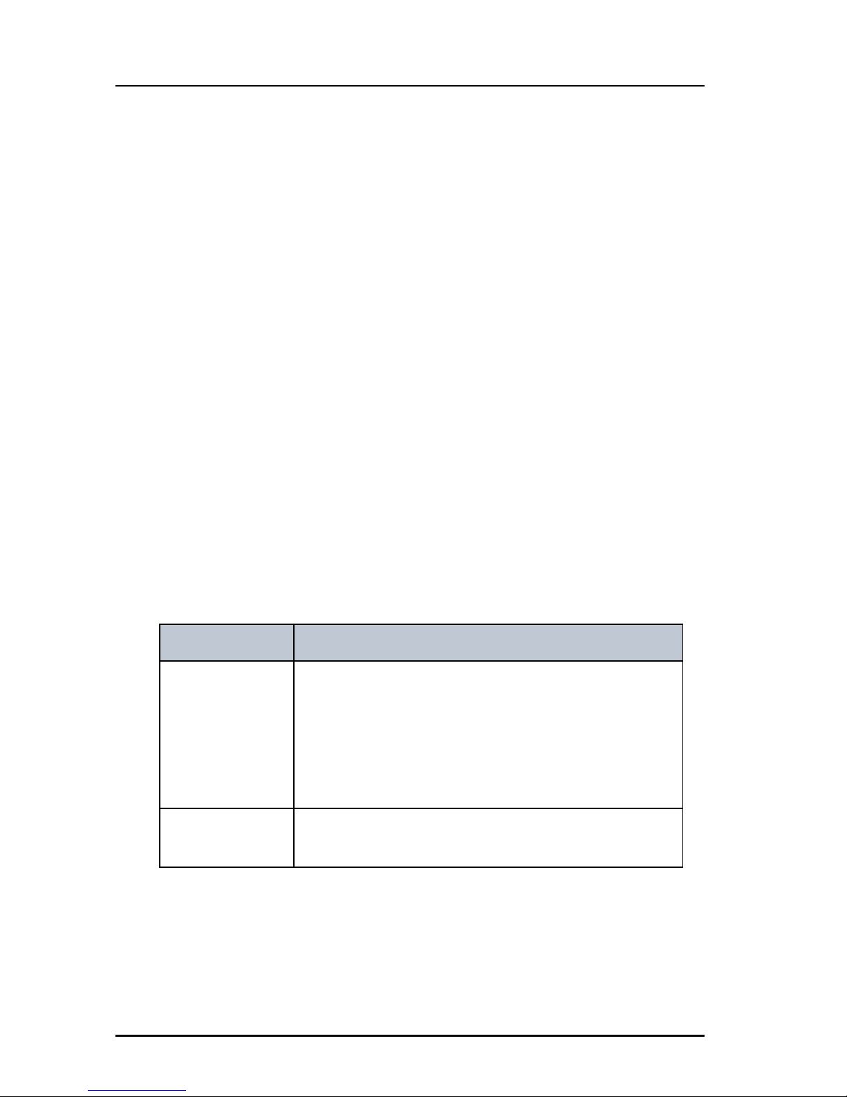
You can enter up to 200 contacts. A contact has the following details:
• Name (up to 12 characters)
• Type (SHIP, GROUP or COAST STATION)
• Channel
The phone book is always sorted alphabetically by contact names. Use the soft
key FILTER to toggle between CONTACTS - ALL, COAST, SHIP or GROUP.
Use the phone book to switch to the preferred channel for a particular contact.
Select the contact to display details and select USE. The channel is selected
and the phone book closes automatically.
Adding a contact to the phone book
To add a contact to the phone book do as follows:
1. Press the soft key PHBOOK.
2. Press the soft key ADD and fill in the details for the new contact.
Contact Description
NAME Enter the name by turning the selector knob to the
desired letter, press the selector knob to accept the
letter and advance to the next letter. To finish press
the soft key OK.
It is also possible to use the keypad to enter the
name.
TYPE Press and turn the selector knob to select SHIP,
GROUP or COAST STATION.
Page 33
Chapter 2: Operation
Phone book 17
22222
Operation
3. Press the soft key SAVE to save the contact information.
4. Press the soft key EXIT to leave the phone book.
Editing a contact
1. Press the soft key PHBOOK.
2. Select the contact.
3. Press and turn the selector knob to browse through the details of the
contact and continue as described in Adding a contact to the phone book
from step 2 onwards.
Deleting a contact
1. Press the soft key PHBOOK.
2. Turn the selector knob to browse to the contact you want to delete.
3. Press the soft key DELETE.
4. Press EXIT to leave the phone book and return to VHF operation.
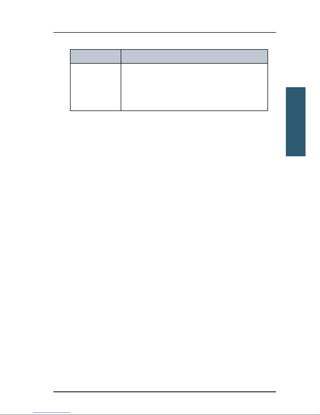
Ch (optional) Press and turn the selector knob to select the
preferred channel for this contact, press the soft key
OK.
It is also possible to use the keypad to enter a
channel.
Contact Description
Page 34

Chapter 2: Operation
18 Replay function
Replay function
Replay allows the operator to playback received voice messages in the
loudspeaker. Recording is activated automatically when a signal is received.
Recording is not possible during playback. Up to 60 tracks or 240 seconds can
be handled. During a power cycle the recorded tracks are deleted.
The recorded channel is displayed. The message length is shown in seconds.
The display shows how old the message is. If the 240 s storage limit is
reached, the oldest data is overwritten.
Replaying recorded messages
Press the Replay button (short press). The latest message
(message) is repeated. Information about this message is
shown in the display.
To stop replaying the message press the soft key STOP.
To rewind through the recorded messages make a long press on the Replay
button.
To stop replaying a message press STOP or the PTT button on the speaking
device.
If a signal is received while in replay mode the display shows in the
display.
Setup
The following setup pages are described in this section of the manual:
• Radio setup
• Channel setup
• Power Supply
• System setup
• Controller setup
Page 35
Chapter 2: Operation
Setup 19
22222
Operation
Accessing a setup page
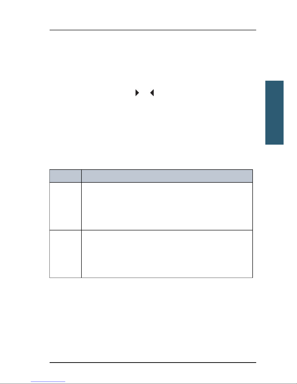
To change a setting in one of the SETUP pages, do as follows
1. Press the soft key SETUP.
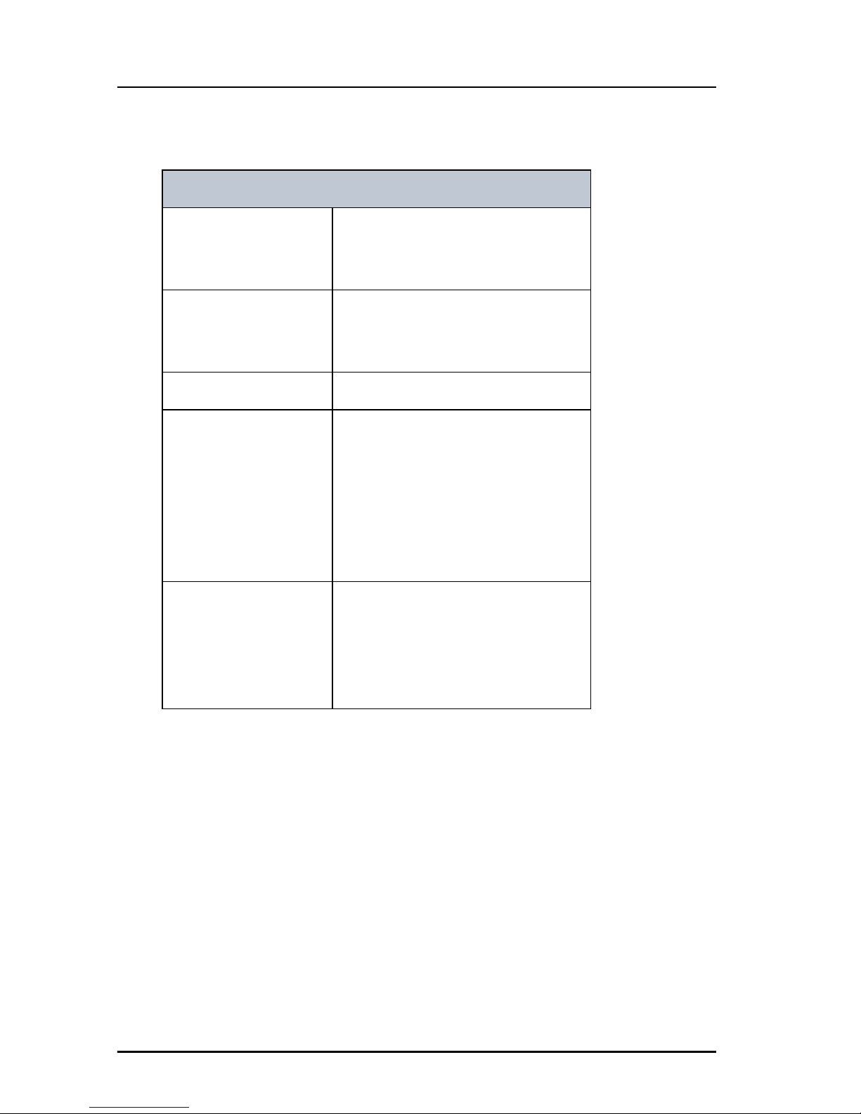
2. Press the arrow soft key or to advance to SETUP page you want to
edit.
3. Turn the selector knob to go to a setting, then press the selector knob to
change the setting.
4. Press EXIT to return to normal radio operation.
Radio setup
Parameter Description
Scan Hang
Time
Scan hang time, in seconds on an active receiving working channel.
The time is measured from the signal is detected. The radio remains
on the channel for the set time interval, if a signal was detected.
OFF: Resumes scanning when signal disappears (default)
4, 6, 8, 10: Hang time in seconds.
Scan
Resume
Scan resume time, in seconds. When the programmed time of
inactivity has elapsed, and when watch/scan has been aborted
using a press on PTT, or after power-up, scan or watch is resumed.
OFF: Automatic resume is deactivated (default)
3, 6, 10, 15, 20, 25, 30: Resume time in seconds.
Page 36
Chapter 2: Operation
20 Setup
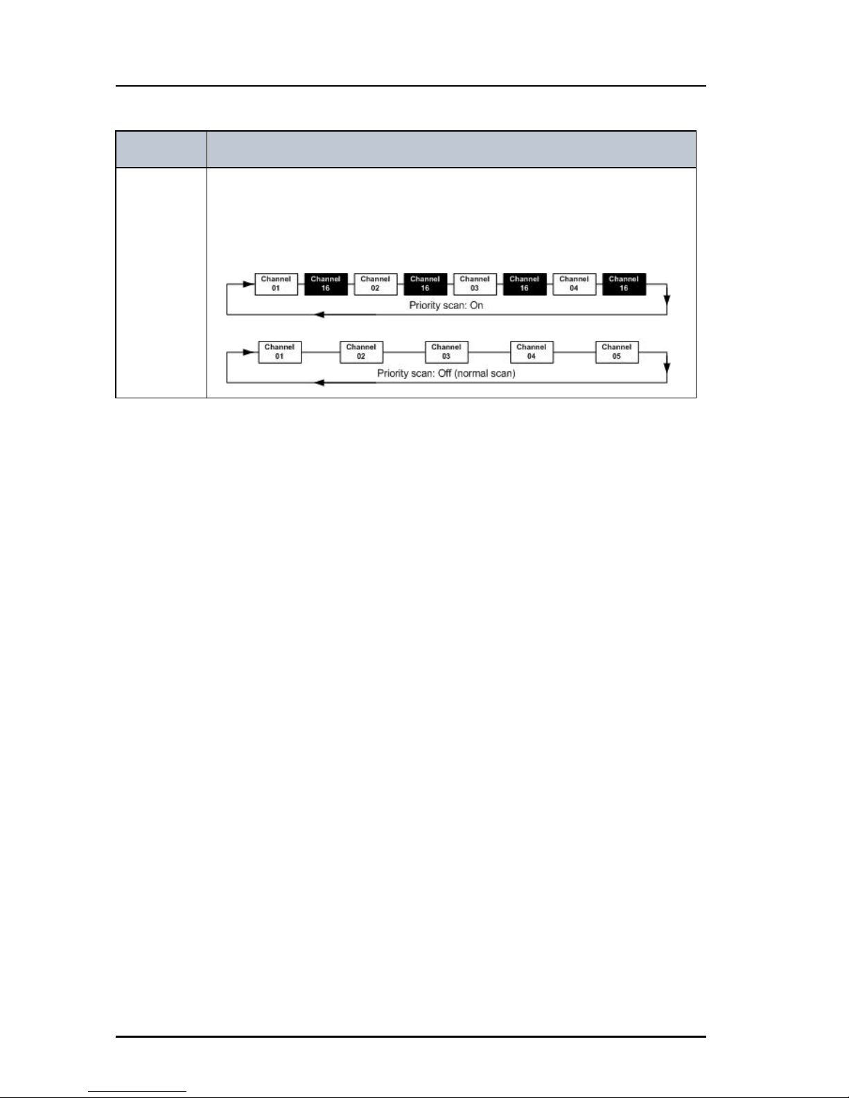
Priority
Scan
ON: All channels tagged for scanning are scanned while monitoring
channel 16. (default).
OFF: Only the channels tagged for scanning are scanned in
sequence, not channel 16, unless it is tagged for scanning.
Parameter Description
Page 37
Chapter 2: Operation
Setup 21
22222
Operation
Channel setup
Power Supply
Parameter Description
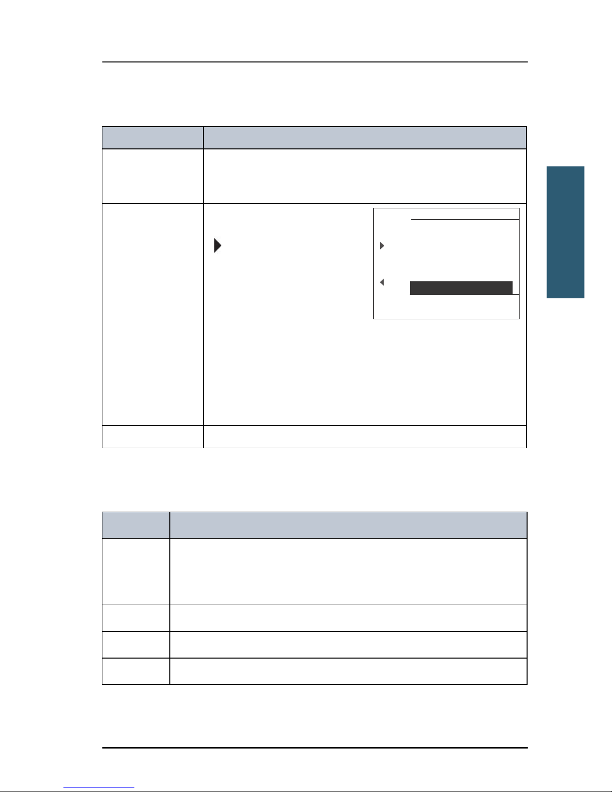
Call Channel Select the channel you want to use as a programmed call
channel. This channel is used as one channel in triple watch
and when you make a long press on the 16/C button.
INT. Channels You can view the channel
settings. Press the soft key
to advance the channel
numbers.
Bandwidth: WIDE (default) or
NARROW
Tagged for scan: OFF (default)
or ON
Edit the service line text by pressing the selector wheel and
enter new name by wheel or keypad.
For customizing, contact your authorized dealer.
Press the soft key EXIT to return to CHANNEL SETUP.
Private Channels As described above.
Parameter Description
Monitor Set this to ENABLED if the radio is connected to a SAILOR 6081 Power
Supply and Charger.
Set this to DISABLED for any other power supply.
Status Visible if ENABLED. Current status of the connected power supply.
Voltage Visible if ENABLED. Current voltage.
Current Visible if ENABLED. Current current.
EXIT INT. Channels
10
Bandwidth:WIDE
Ch: 1
Rx: 160.6500 MHz
Tagged for scan: OFF
PORT-PUBLIC
Tx: 156.0500 MHz
Page 38
Chapter 2: Operation
22 Setup
System setup
Controller setup
Each of the controlling devices connected and powered has its own setting.
The available settings may vary from controllers applied.
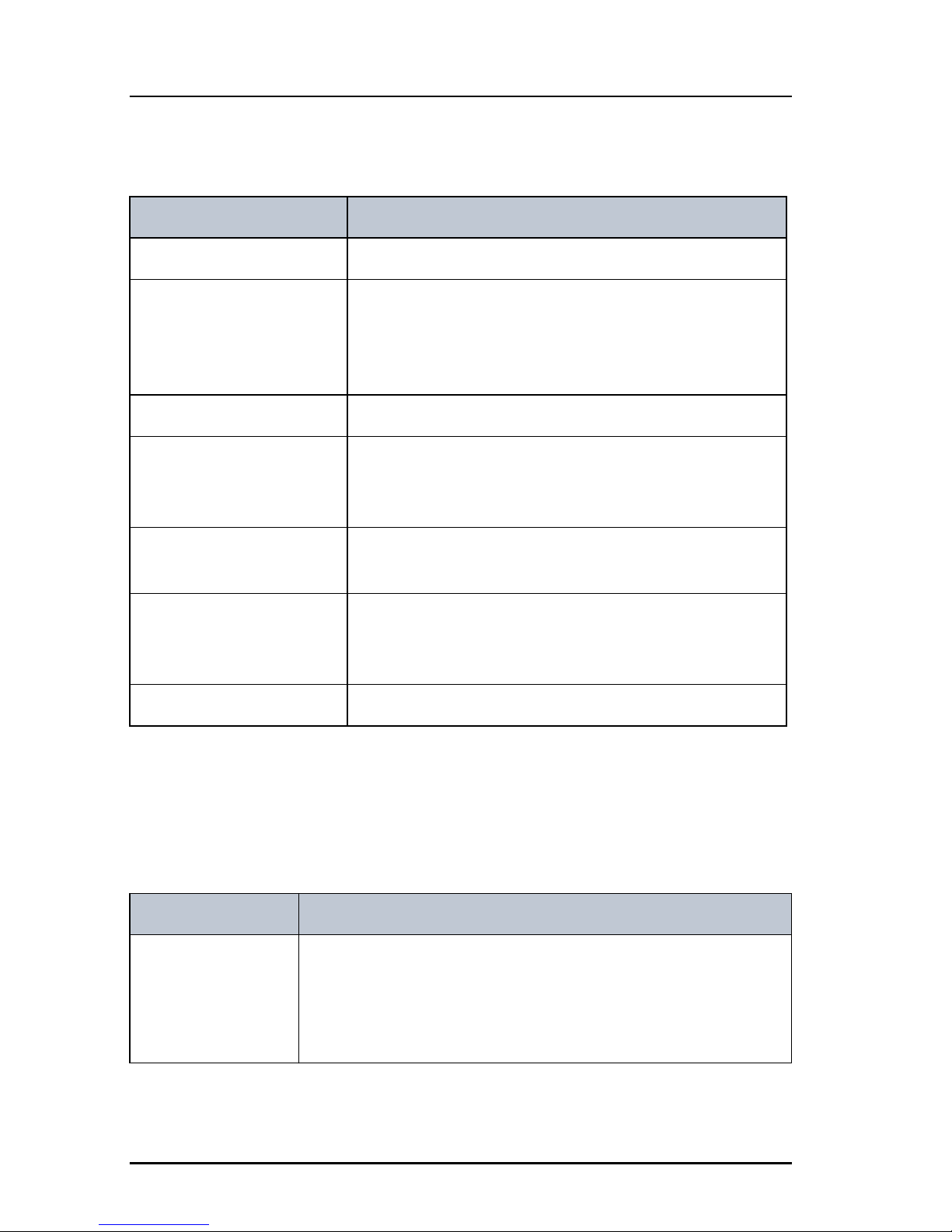
SYSTEM SETUP Description
System time & Date View and set system time and date
Inactivity timeout Inactivity time-out to exit functions (e.g. in setup) and
return to the application.
Range: 1 to 30 minutes, in 1 minute steps
Default: 10 min.
Language English
Theme Changes the display colour.
BlackOnWhite (default)
WhiteOnBlack
Factory Defaults Resets the radio to factory defaults. Press the selector
knob and confirm the reset to factory default.
Radio Info: SW Version: Software version of the radio
S/N: Serial number of the radio
IP: IP address of the radio
Password Not used.
Controlling device Description
Handset 1 vol: Adjust earpiece volume for handset 1: ON, can be adjusted
from OFF to 100, in steps of 5.
Note: The handset connected to the front connector has top
priority and is configured to ON.
Page 39
Chapter 2: Operation
Setup 23
22222
Operation
Top-level standby soft-key functions and setup pages
Handset 2 vol: Adjust earpiece volume for handset 2: ON, can be adjusted
from OFF to 100, in steps of 5.
Ext. speaker FIX: Fixed level is set for external speaker
REL: Relative level following volume adjustment of the
internal speaker
Ext. fixed vol: External speaker fixed volume:
OFF, 5 to 100 in steps of 5
Wheel lock: You can set a time interval after which the SQ, volume and
selector knobs are locked and protected against
unintentional use. Then a lock symbol is shown in the
display. Press any key to unlock the knobs.
OFF, 10s, 20s, 30s, 40s, 50s, 60s
Controlling device Description
Top-level standby
SCAN EXIT
START
TAG
FILTER
LOCAL
PHBOOK EXIT
ADD
FILTER
DEL
SETUP EXIT
Page 40
Chapter 2: Operation
24 Setup
Setup pages
RADIO SETUP Scan Hang Time
Scan Resume
Priority Scan
CHANNEL SETUP Call Channel
Int. Channels
Private Channels
POWER SUPPLY Monitor
SYSTEM SETUP System time & date
Inactivity timeout
Language
Theme
Factory Defaults
Password
Radio Info
CONTROLLER SETUP Handset 1 vol:
Handset 2 vol:
Ext. Speaker
Ext. fixed vol:
Wheel lock
Page 41

25
Chapter 3
33333
Service & maintenance
Service & maintenance 3
Contact for support
Contact your authorized dealer for technical service and support of the VHF
radio. Before contacting your authorized dealer you can go through the
troubleshooting guide to solve some of the most common operational
problems.
Maintenance
Preventive maintenance
Maintenance of the SAILOR 6249 VHF Survival Craft can be reduced to a
maintenance check at each visit of the service staff. Inspect the radio for
mechanical damages, salt deposits, corrosion and any foreign material. Due to
its robust construction and ruggedness the radio has a long lifetime. Anyway it
must carefully be checked at intervals not longer than 12 months - dependent
on the current working conditions.
Salt deposits
In case the equipment has been exposed to sea water there is a risk of salt
crystallization on the keys and knobs and they may become inoperable. Clean
the VHF radio and speaker microphones with fresh water.
Error messages and warnings
Errors and warning messages are shown in the display and are read-only.
Page 42
Chapter 3: Service & maintenance
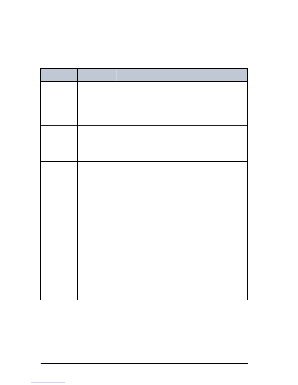
26 Troubleshooting guide
Troubleshooting guide
Action Symptom Remedy
The radio
will not turn
on
The display is
empty.
Check if power is present.
Check fuse which is placed in the power connector.
Check performance of power supply if connected to
one.
No communication
The loudspeaker is
mute.
Check the antenna installation.
Check antenna cable.
Check Handmicrophone and cable.
Device
failure
If any of the checks and tests described in this
section do not assist in resolving the difficulties
experienced in the operation and/or performance
of the VHF installation, a fault may have developed
in the VHF radio itself.
When contacting an authorized Thrane & Thrane
representative be sure to provide as much
information as possible describing the observed
behavior - also including the type of the VHF radio,
its serial number, and software release version
(both found in the setup menu Controller Setup).
WARNING:
POWER
SUPPLY
LOST
CONTACT
Power supply
status cannot
be
monitored.
In Setup, Power Supply, set Monitor to disabled.
You can only monitor the power supply if the radio
is powered by a SAILOR 6081 Power Supply Unit
and Charger.
Page 43
Chapter 3: Service & maintenance
Troubleshooting guide 27
33333
Service & maintenance
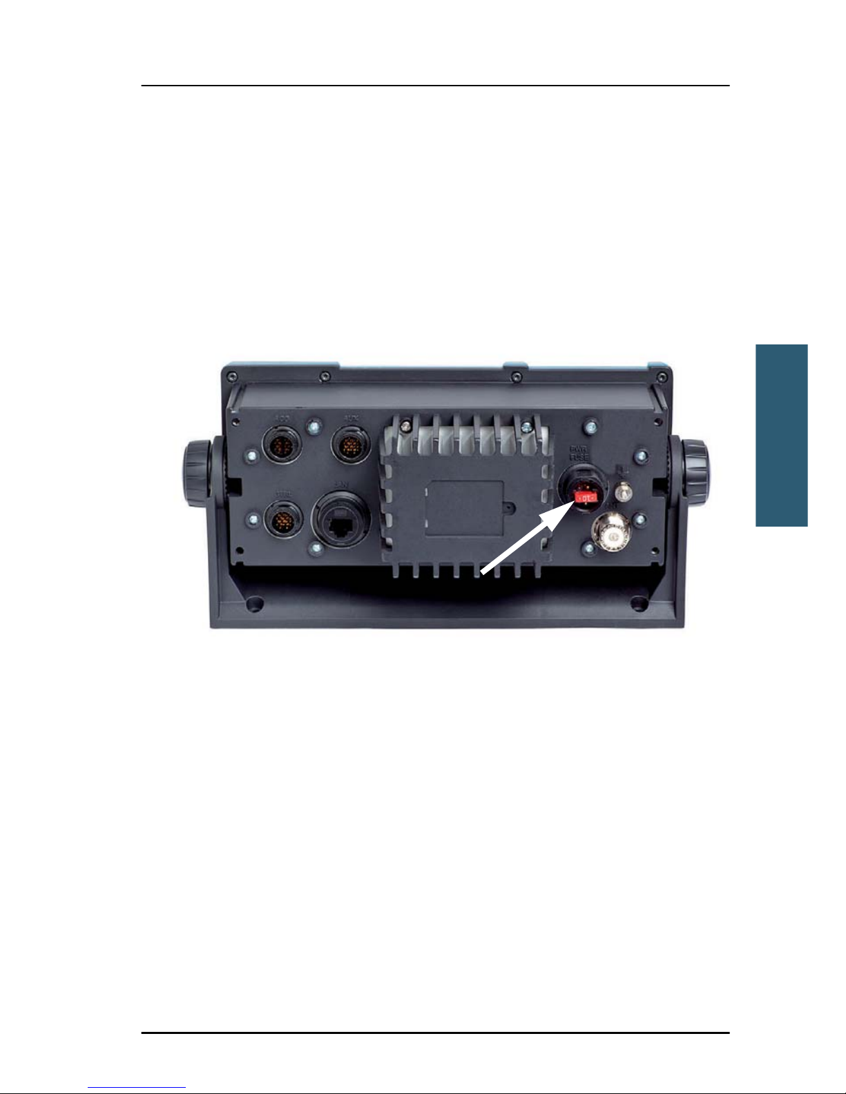
Replacing the fuse in the power connector
One fuse is installed in the power connector. If the fuse is blown, do as
follows:
1. Track down why the fuse was blown and solve the problem.
2. Take out the old fuse.
3. Insert the new fuse. The fuse rating is 10 A T.
Figure 3-1:
Page 44
Chapter 3: Service & maintenance
28 Troubleshooting guide
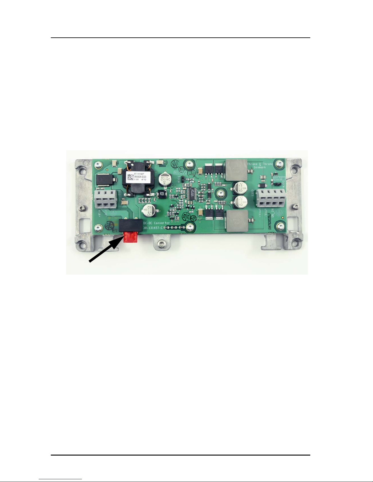
Replacing the fuse in the SAILOR 6090 Power Converter
One fuse is installed in the SAILOR 6090 Power Converter. If the fuse is blown,
do as follows:
1. Track down why the fuse was blown and solve the problem.
2. Take out the old fuse.
3. Insert the new fuse. The fuse rating is 10 A T.
Figure 3-2:
Page 45

Chapter 3: Service & maintenance
Warranty and returning units for repair 29
33333
Service & maintenance
Warranty and returning units for repair
Should your Thrane & Thrane product fail, please contact your dealer or
installer, or the nearest Thrane & Thrane partner. You will find the partner
details on thrane.com where you also find the Thrane & Thrane Self Service
Center web-portal, which may help you solving the problem.
Your dealer, installer or Thrane & Thrane partner will assist you whether the
need is user training, technical support, arranging on-site repair or sending
the product for repair.
Your dealer, installer or Thrane & Thrane partner will also take care of any
warranty issue.
Repacking for shipment
Should you need to send the product for repair, please read the below
information before packing the product.
The shipping carton has been carefully designed to protect the SAILOR 6249
VHF Survival Craft and its accessories during shipment. This carton and its
associated packing material should be used when repacking for shipment.
Attach a tag indicating the type of service required, return address, part
number and full serial number. Mark the carton FRAGILE to ensure careful
handling.
If the original shipping carton is not available, the following general
instructions should be used for repacking with commercially available
material.
1. Wrap the defective unit in heavy paper or plastic. Attach a tag indicating
the type of service required, return address, part number and full serial
number.
2. Use a strong shipping container, e.g. a double walled carton.
Note
Correct shipment is the customer’s own responsibility.
Page 46

Chapter 3: Service & maintenance
30 Warranty and returning units for repair
3. Protect the front- and rear panel with cardboard and insert a layer of
shock-absorbing material between all surfaces of the equipment and the
sides of the container.
4. Seal the shipping container securely.
5. Mark the shipping container FRAGILE to ensure careful handling.
Failure to do so may invalidate the warranty.
Page 47
31
Appendix A
AAAAA
Technical pecifications
Technical pecifications A
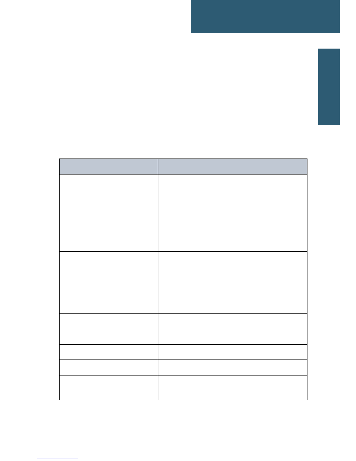
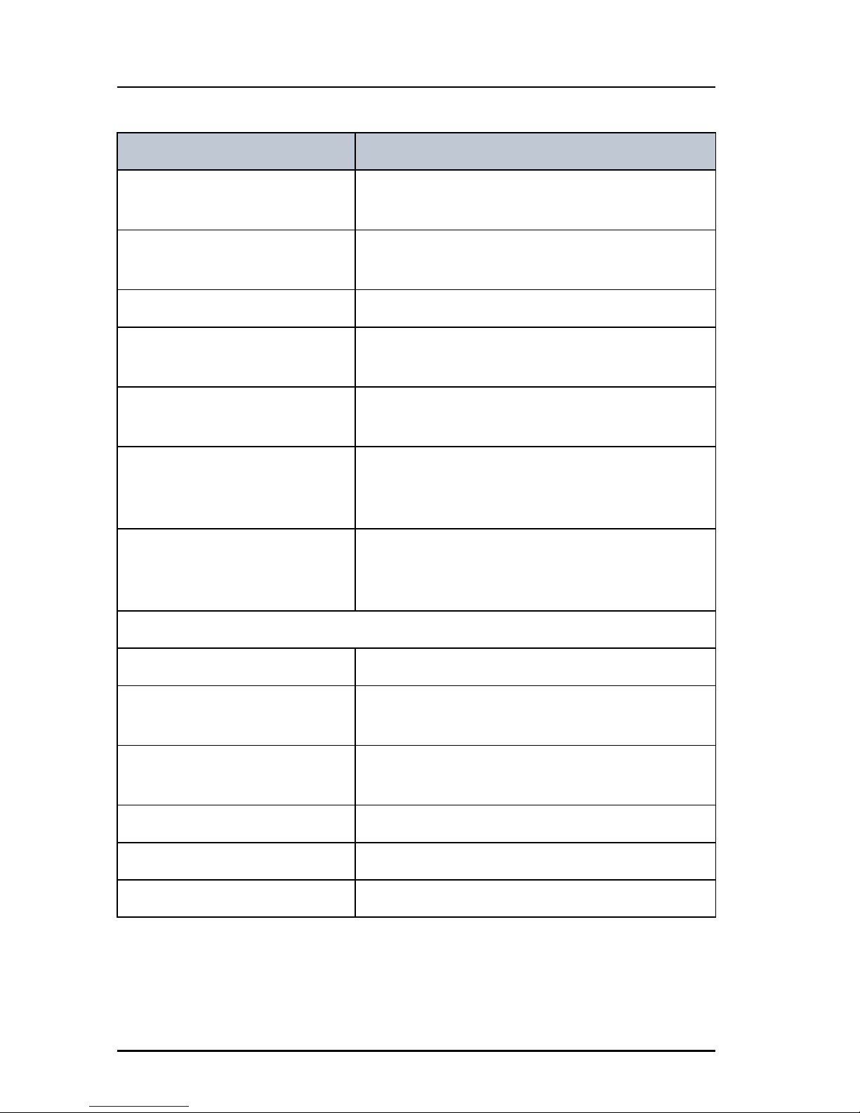
Transceiver unit SAILOR 6249 VHF Survival
Craft
Item Specification
Weight SAILOR 6249 VHF
Survival Craft
< 1.50 kg (3.3 lbs) approximately
Box weight
SAILOR 6249 VHF Survival Craft
3.8 kg (8.4 lbs) approximately, including SAILOR
6201 Handset with cradle6202 Hand Microphone
and wall mount cradle, SAILOR 6204 Control
Speaker Microphone and Installation and user
manual in box.
Dimensions Height: Outer dimension 107 mm, hole height for
flush mount 89 mm
Width: Outer dimension 241 mm, hole width for
flush mount 227 mm
Depth: Outer dimension from front of knobs 132
mm, depth for flush mount 94 mm
Operating temperature -25°C to 55°C (5°F to 131°F)
Storage temperature -30°C to 80°C (-22°F to 176°F)
Power supply 12 VDC Nominal (10,8– 15,6 VDC)
Current consumption Max. 7 A
Current consumption at 12 VDC
(no accessories connected)
RX: 0.5 A
TX: 5 A
Page 48
Chapter A: Technical pecifications
32 Transceiver unit SAILOR 6249 VHF Survival Craft
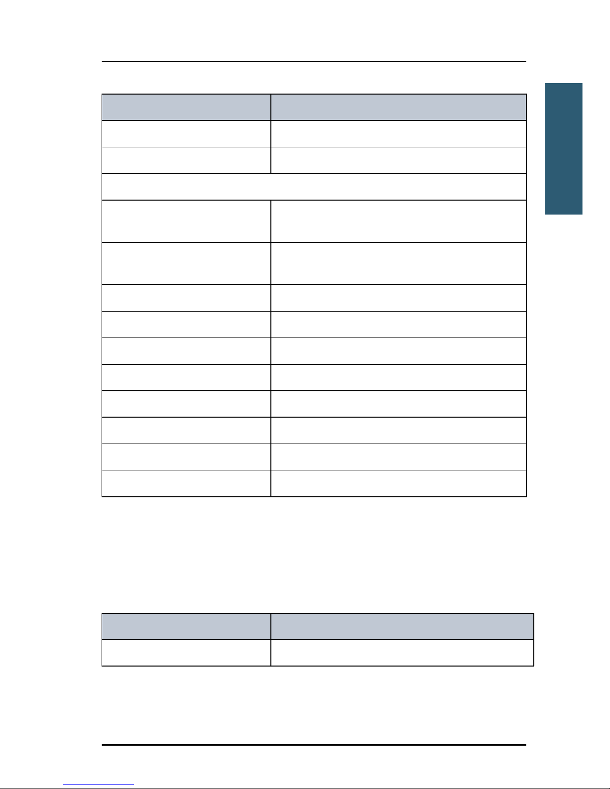
Current consumption at 12 VDC
(all accessories connected)
RX: 0.7 A
TX: 7 A
Frequency range TX: 156,000 MHz — 157,425 MHz,
RX: 156,000 MHz — 163.425 MHz
Channel spacing 25 kHz, all international maritime channels
Number of P channels The radio may be programmed with up to 100
private channels in all channel modes.
Modulation
25 kHz 16K0G3E
Antenna 50 Ohm antenna, 50 Ohm female SO239 for
PL259 plug
Water ingress IPx8 and IPx6 all over. For flush-mount
installations a sealing gasket is included in the
delivery.
Transmitter
Transmit power Hi/Lo: 25 W and 1 W
RF output power High: 25 W +0 dB / - 1.5 dB
Low: 1 W +0 dB / - 1.5 dB
RF output power, Canada High: 21 W ±0.75 dB
Low: 0.8 W ±0.75 dB
Frequency error Below 500 Hz
Adjacent channel power Below 75 dB
Conducted spurious emission Below 0.25 W
Item Specification
Page 49
Appendix A: Technical pecifications
SAILOR 6090 Power Converter 24—12 V 33
AAAAA
Technical pecifications
SAILOR 6090 Power Converter 24—12 V
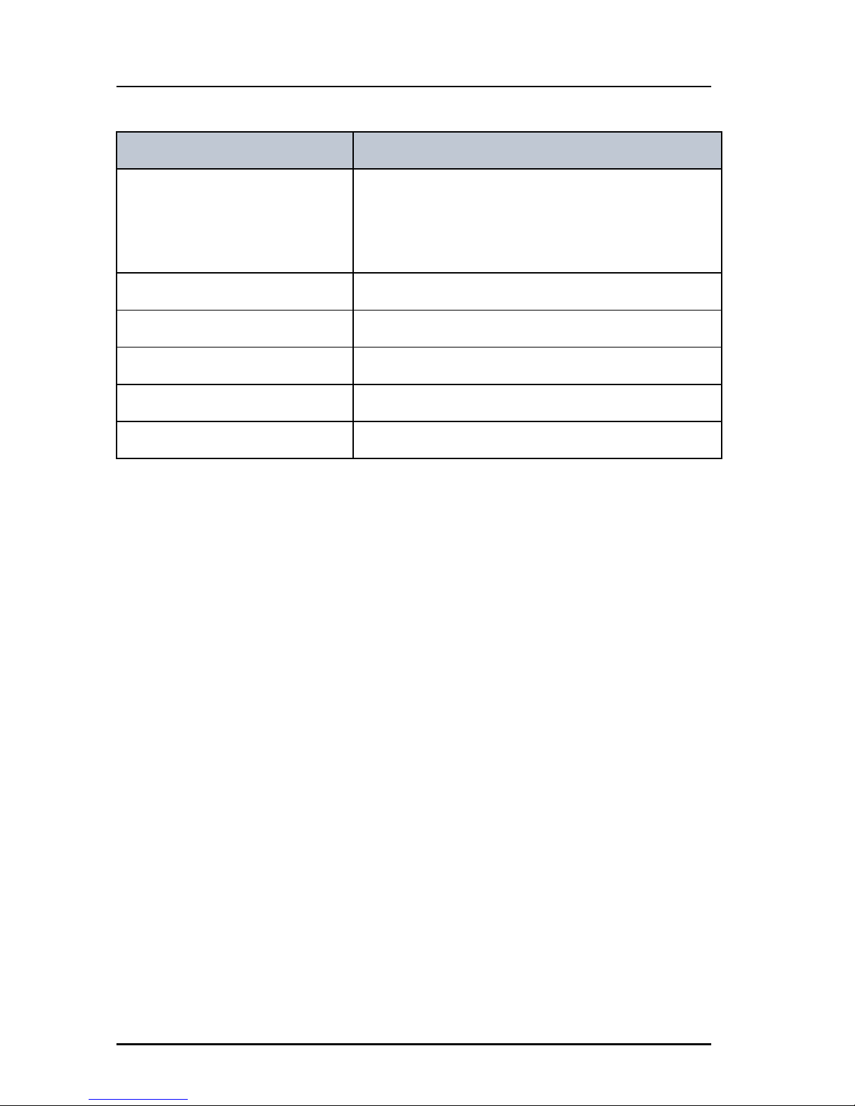
Distortion Below 3%
S/N ratio Better than 46 dB
Receiver
Sensitivity < -119 dBm typically @ 20 dB SINAD CCITT
weighted
LF power Built-in loudspeaker: 6 W (at 5 kHz dev./1 kHz
tone). External loudspeaker: 6 W / 8 Ohm
Distortion Below 5%
S/N ratio Better than 43 dB
Spurious emissions Below 2 nW
Spurious response rejection More than 74 dB
Intermodulation response More than 73 dB
Co-channel rejection Better than —10 dB
Adjacent channel selectivity More than 74 dB
Blocking level More than 94 dBV
Item Specification
Item Description
Weight 300 g
Page 50
Appendix A: Technical pecifications
34 SAILOR 6090 Power Converter 24—12 V
Dimensions Height: 33 mm
Width: 190 mm
Depth: 85 mm
Operating temperature -25°C to 55°C (5°F to 131°F)
Storage temperature -30°C to 80°C (-22°F to 176°F)
Input voltage 21—32 VDC
Output voltage 12.5 VDC
Output current (max.) 8 A
Item Description
Page 51
35
Appendix B
BBBBB
Maritime channels
Maritime channels B
International channels (INT)
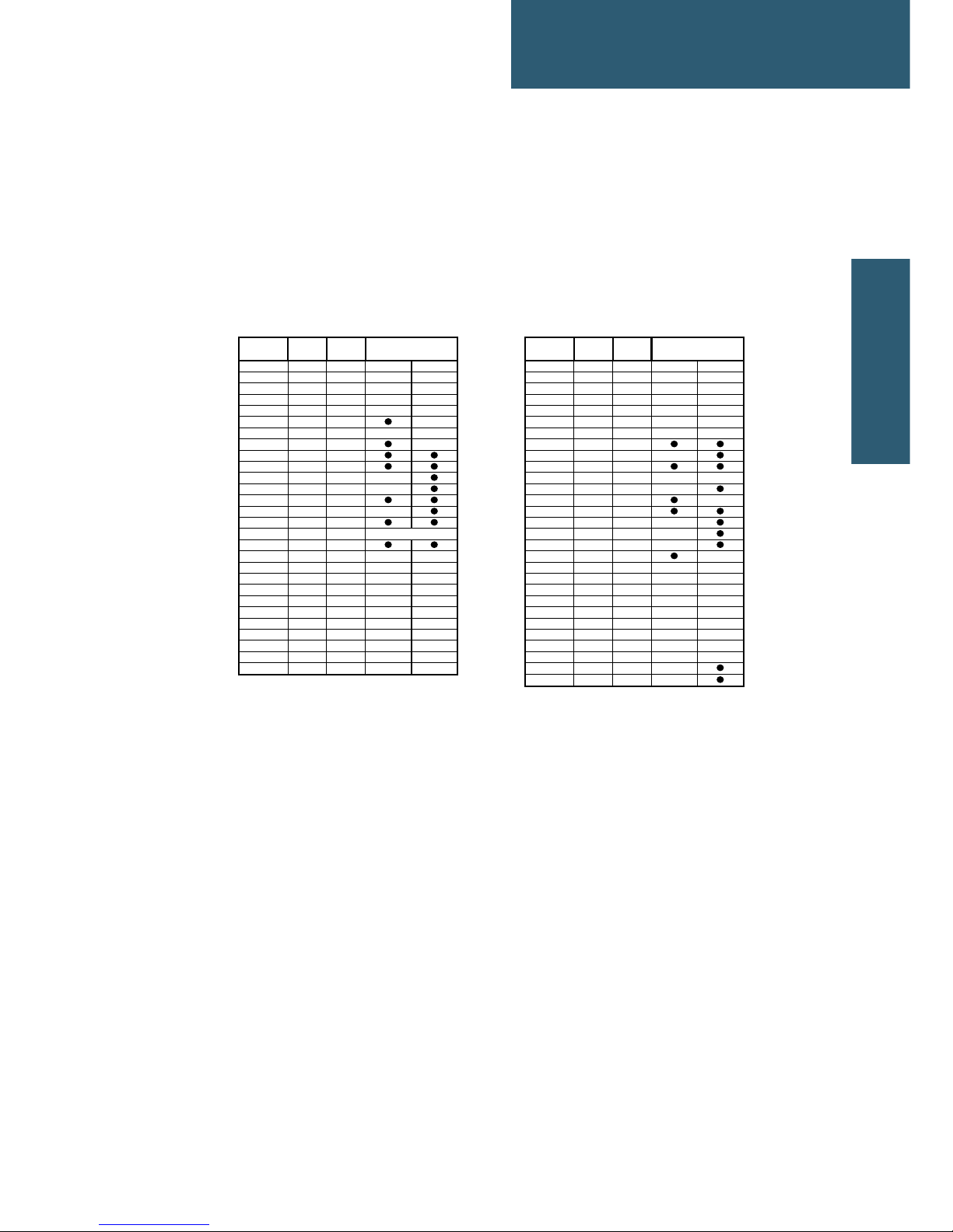
L) 1 W TX power
*) Channel 87 and 88 became simplex channels following the introduction of
AIS1 at 161.975 MHz and AIS2 on 162.025 MHz.
Private channels
Up to 100 licensed private channels may be specified. For programming the
private channels contact your local dealer.
Channels TX RX SIMPLEX Channels TX RX SIMPLEX
MHz MHz Intership Port MHz MHz Intership Port
1 156,050 160,650 60 156,025 160,625
2 156,100 160,700 61 156,075 160,675
3 156,150 160,750 62 156,125 160,725
4 156,200 160,800 63 156,175 160,775
5 156,250 160,850 64 156,225 160,825
6 156,300 156,300 65 156,275 160,875
7 156,350 160,950 66 156,325 160,925
8 156,400 156,400 67 156,375 156,375
9 156,450 156,450 68 156,425 156,425
10 156,500 156,500 69 156,475 156,475
11 156,550 156,550 70 156,525 156,525
DSC DSC
12 156,600 156,600 71 156,575 156,575
13 156,650 156,650 72 156,625 156,625
14 156,700 156,700 73 156,675 156,675
15 156,750 156,750 74 156,725 156,725
16 156,800 156,800 75 156,775 156,775
L)
17 156,850 156,850 76 156,825 156,825
L)
18 156,900 161,500 77 156,875 156,875
19 156,950 161,550 78 156,925 161,525
20 157,000 161,600 79 156,975 161,575
21 157,050 161,650 80 157,025 161,625
22 157,100 161,700 81 157,075 161,675
23 157,150 161,750 82 157,125 161,725
24 157,200 161,800 83 157,175 161,775
25 157,250 161,850 84 157,225 161,825
26 157,300 161,900 85 157,275 161,875
27 157,350 161,950 86 157,325 161,925
28 157,400 162,000 87 157,375 157,375 *)
88 157,425 157,425 *)
Distress & calling
Page 52

Appendix B: Maritime channels
36 International channels (INT)
Page 53

37
Glossary
CCCCC
Glossary
Glossary C
A
AIS Automatic Identification System, a short range coastal tracking
system used on ships and by Vessel Traffic Services for identifying
and locating vessels by electronically exchanging data with other
nearby ships.
G
GPL General Public License
L
LGPL Lesser General Public License
P
PTT Push To Talk
T
TU Transceiver Unit
V
VDR Voyage Data Recorder, a data recording system designed for all
vessels required to comply with the IMO’s International
Convention SOLAS Requirements in order to collect data from
various sensors on board the vessel.
VHF Very High Frequency
Page 54

Chapter Glossary:
38
Page 55

39
Index
DDDDD
Index
Index D
Numerics
16/C, 8, 11
A
action line, display, 3
activate
scan resume, 19
scanning, 15
watch, 14
ADD, 16
add a contact, 16
adjust
speaker volume, 8
squelch, 10
attenuation control, 14
B
backlight, 1
dim, 8
browse channels, 8
C
call
Distress procedure, vii
call channel, 13
programming, 21
channel
add to scan, 15
remove from scan, 15
select, 8, 9
working, 8, 9
channel table
INT, 35
PRIV, 35
channels
international, 35
primary, 13
private, 13
Colour theme, 22
configuration
system example, 5
contact, 25
adding, 16
deleting, 17
editing, 17
controls, front plate, 2
D
deactivate
watch, 14
default reset, 22
DELETE, 17
delete contact, 17
dim, 8
display, 3
display colour
change, 22
distress channel, 8, 11
Distress procedure, vii
document number, this manual, i
E
editing a contact, 17
Emergency call sheet, xi
emergency calls, vii
error messages, 25
Page 56

Index
40
F
factory defaults, 22
FILTER, 15
frequency range, VHF, 32
front plate, controls, 2
fuse
Power Converter, 28
VHF radio, 27
H
Hand Microphone, 9
hang time, 19
how to replace, 28
I
installation guide, A3, xi
installation manual, xi
INT, 35
IP address, 22
IP rating, 32
K
key 16/C, 8, 11
keys on front plate, 2
knob
selector, 2
volume, 2
L
license
software, ii
louder, volume, 8
low power
set to 1 W, 14
M
manual, document number, i
maritime channels, 35
MAYDAY, vii
menu, overview, 23
message
replay, 18
monitor power supply, 21
mute speaker, 10
N
night vision, how to dim, 8
P
phone book, 16
add contact, 16
delete a contact, 17
edit a contact, 17
power
fuse, 27
off, 8
on, 8
Power Converter
fuse, 28
power supply
monitor, 21
priority scan, 20
PRIV, 35
private channels, 13, 32, 35
PTT button, 11
Page 57

Index
41
DDDDD
Index
R
radio call
making, 12
receiving, 11
reduced transmission power, 14
replay, 1, 18
button, 2
reset to default, 22
resume time, 19
RF exposure hazards, iv
S
safety summary, iv
salt deposits, 25
scan
add channel, 15
hang time, 19
priority, 20
remove channel, 15
resume time, 19
resume, activate, 19
start, 15
selector knob, 2, 8
serial number, 22
service line, display, 3
setup
controller, 22
overview, 23
parameters, 23
Radio, 19
system, 22
watch, 19
simplex, 1
soft key, 9
ADD, 16
DELETE, 17
FILTER, 15
STOP, 18
TAG, 15
WATCH, 14
softer, volume, 8
software license, ii
Software version, 22
speaker volume, 8
speaking devices, 9
specifications, 31
squelch, 10
squelch control, 2, 10
STOP, 18
stop
replaying a message, 18
watch or scan, 14, 15
support, 25
system configuration
example, 5
system setup, 22
T
TAG, 15
remove, 15
tagged channels
view, 15
technical data, 31
temperature
operational, 31, 34
storage, 31, 34
theme
colour, change, 22
timeout, 22
Page 58

Index
42
U
UTC time, 3
V
VHF
channels, 13
frequency range, 32
volume
louder, 8
softer, 8
speaker, 8
Volume knob, 2
W
warnings, 25
warranty, 29
limitation, iv
WATCH, 14, 15
watch
setup, 19
start, 14
stop, 14
water ingress, 32
weight, 31, 33
working channel, 8, 9
Page 59

Page 60

98-133865-C
[email protected] • thrane.com
 Loading...