

Sailor 6222 Installation Manual
What’s in the box?
What do I need to fi t it?
How to install the VHF on desktop and overhead
How to install the VHF fl ush mount
INSTALLATION GUIDE
SAILOR 6222 VHF DSC
info@thrane.com • thrane.com
98-1
32281-B
How to install the handset
Power Drill Jigsaw Screwdriver
TORX 20
Drill for M4 or
Ø3.9 self-tapping
U-Mounting
Bracket
Transceiver Gasket
Flush Mount
Bracket (2 pcs.)
Fuse
6.3x3.2mm
(10AT)
Cradle
Wheel Knob
(2 pcs.)
Screw M4x45
TORX 20
(5 pcs.)
Square Nut
M4x7x2.2
(5 pcs.)
Screw M4x12
TORX 20 (2 pcs.)
Screw ø3.9x19
TORX 20 (2 pcs.)
Screw M4x12
TORX 20
(5 pcs.)
Screw ø3.9x19
TORX 20
(5 pcs.)
Handset
Very important information!
Do not remove the membrane.
If you remove the membrane the
radio will not be waterproof.
This Handset has a hook-on/off function,
which is activated by a small magnet embedded
in the cradle.
The cradle must be installed as illustrated in
order to ensure the hook-on/off functionality
of the Handset.
75mm
62mm
226mm
* 120mm
min. 100mm
Space for handset access
Space for cable and handset cable
54mm
45mm
135mm
39655C
Tilting ±20°
Dimensions for the SAILOR 6222 VHF DSC
Cap for LTW
RJ45
Connector
Cap for LTW
BD/BU
Connector
Fuse
6.3x3.2mm
(10AT)
Screw M4x12
TORX 20 (4 pcs.)
Screw ø3.9x19
TORX 20 (4 pcs.)
SAILOR 6090
Power Converter
User
Manual
Emergency
Call
EMERGENCY CALL
SAILOR VHF and MF/HF
MM
MM
M
AA
AA
A
YY
YY
Y
DD
DD
D
AA
AA
A
YY
YY
Y
NANA
NANA
NA
MEME
MEME
ME of the
VV
VV
V
EE
EE
E
SS
SS
S
SS
SS
S
ELEL
ELEL
EL in distress
CC
CC
C
ALAL
ALAL
AL
LL
LL
L
SS
SS
S
IGNIGN
IGNIGN
IGN or other
IDENIDEN
IDENIDEN
IDEN
TT
TT
T
IFICIFIC
IFICIFIC
IFIC
AA
AA
A
TT
TT
T
IONION
IONION
ION
MM
MM
M
MM
MM
M
S
S
SS
S
II
II
I
(If t
he
initial alert is sent by DSC)
PP
PP
P
OO
OO
O
SS
SS
S
ITIT
ITIT
IT
IONION
IONION
ION
given as
ll
ll
l
atat
atat
at
itit
itit
it
udeude
udeude
ude and
longitlongit
longitlongit
longit
udeude
udeude
ude
or
If latitude and longitude are not known
or if time is insufficient,
in relation to a known geographical location
NANA
NANA
NA
TURETURE
TURETURE
TURE of distress
Kind of
AA
AA
A
SS
SS
S
SS
SS
S
II
II
I
SS
SS
S
TT
TT
T
ANCANC
ANCANC
ANC
EE
EE
E required
Any other useful
INFINF
INFINF
INF
OROR
OROR
OR
MM
MM
M
AA
AA
A
TT
TT
T
IONION
IONION
ION
MM
MM
M
AA
AA
A
YY
YY
Y
DD
DD
D
AA
AA
A
YY
YY
Y
-M-M
-M-M
-M
AA
AA
A
YY
YY
Y
DD
DD
D
AA
AA
A
YY
YY
Y
-M-M
-M-M
-M
AA
AA
A
YY
YY
Y
DD
DD
D
AA
AA
A
YY
YY
Y
This is
NANA
NANA
NA
ME-NAME-NA
ME-NAME-NA
ME-NA
ME-NAME-NA
ME-NAME-NA
ME-NA
MEME
MEME
ME
CC
CC
C
ALAL
ALAL
AL
LL
LL
L
SS
SS
S
IGNIGN
IGNIGN
IGN
or other IDENTIFICATION
MM
MM
M
MM
MM
M
SS
SS
S
II
II
I
(If the initial alert is sent by DSC)
Use the
HANDHAND
HANDHAND
HAND
SS
SS
S
ETET
ETET
ET
for voice calling
LL
LL
L
ifif
ifif
if
t Ct C
t Ct C
t C
ovov
ovov
ov
erer
erer
er
PP
PP
P
rr
rr
r
ee
ee
e
ss
ss
s
s RED Buttons RED Button
s RED Buttons RED Button
s RED Button
until beep sounds continuously
(more than 3 seconds)
SHIP‘s NAME:
CALLSIGN:
MMSI:
OWN OWN
OWN OWN
OWN
IDID
IDID
ID
99-132140
Press
VHF
MF
HF4
HF6
HF8
HF12
HF16
Channel 70
2187.5 kHz
4207.5 kHz
6312.0 kHz
8414.5 kHz
12577.0 kHz
16804.5 kHz
Channel 16
2182.0 kHz
4125.0 kHz
6215.0 kHz
8291.0 kHz
12290.0 kHz
16420.0 kHz
- - - - -
2174.5 kHz
4177.5 kHz
6268.0 kHz
8376.5 kHz
12520.0 kHz
16695.0 kHz
DD
DD
D
SCSC
SCSC
SC
RR
RR
R
adiadi
adiadi
adi
otot
otot
ot
elephonelephon
elephonelephon
elephon
yy
yy
y
NBDPNBDP
NBDPNBDP
NBDP
DIDI
DIDI
DI
SS
SS
S
TRETRE
TRETRE
TRE
SS
SS
S
SS
SS
S
and C and C
and C and C
and C
OMOM
OMOM
OM
MM
MM
M
UNICUNIC
UNICUNIC
UNIC
AA
AA
A
TT
TT
T
IONION
IONION
ION
FREQUENCIEFREQUENCIE
FREQUENCIEFREQUENCIE
FREQUENCIE
SS
SS
S
_ _ _ _ _ _ _ _ _ _ _ _ _ _ _ _ _ _ _ _ _ _ _ _ _ _ _ _ _ _ _ _ _ _ _ _
Remember to use the correct HF-procedures
Don‘t forget your EPIRB is the secondary means of
alerting
_ _ _ _ _ _ _ _ _ _ _ _ _ _ _ _ _ _ _ _ _ _ _ _ _ _ _ _ _ _ _ _ _ _ _ _
98-132369-A
SAILOR 6222 VHF DSC
USER MANUAL
Power
Cable
Connection Cable,
1 m
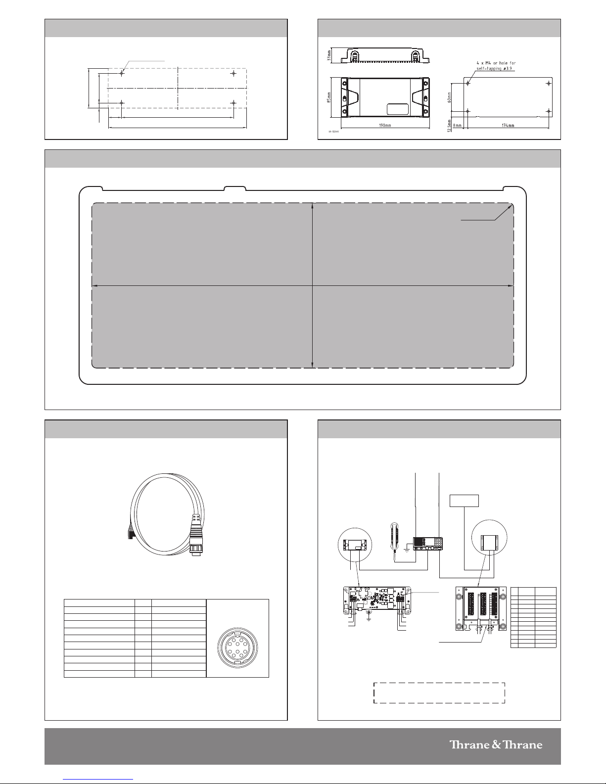
Flush mount template
Remove material from shaded area only!
89mm
227mm
R2.5mm x 4
info@thrane.com • thrane.com
98-
132281-B
Scale 1:1
Cutout template for fl ush mounting of the VHF
VHF DSC
Receiver
GPS
99-132804
SAILOR 6222
Handset
SAILOR 6201
Power Converter
SAILOR 6090
12V DC
SAILOR 6207
Connection Box
for Parallel Handsets
406209-941
Cable
NMEA
ACC
Ground
12V DC
+Vout (Red)
-Vout (Blue)
Remote on/off
NC
Screen/Ground
-Vin
+Vin
24V DC
Remove jumper
for remote on/off
from VHF
color
designation
Wire
Signal
Pin
All cable screens must not
touch any mechanical parts
Brown
Blue
White
Green
Yelow
Grey
Pink
Red
Black
Orange
Screen
NMEA+
NMEANMEA- HS
NMEA+ HS
MIC+
EAR
HOOK/PTT
+Batt
-Batt
Screen
Screen
Screen
1
2
3
4
5
6
7
8
9
10
11
12
J1 J2
J3
1
2
3
4
5
6
7
8
9
10
11
12
1
2
3
4
5
6
7
8
9
10
11
12
12
11
VHF 62XXHandset 2
Handset 1
10
9
8
7
6
5
4
3
2
1
Aerial
RX/TX
Aerial
RX/DSC
24V DC
IMPORTANT!
If this template was printed from an electronic
fi le or copied, scaling (1:1) may not be correct.
Consequently do not attempt to use a printed
or copied template without prior checking of
dimensions.
How to connect the GPS and the Chart Plotter - Cable connections
Drilling plan on desktop and overhead How to install the SAILOR 6090 Power Converter
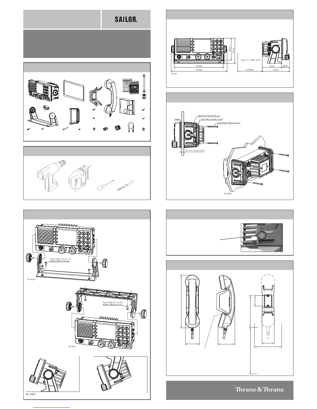
Drilling plan
99-131985
200mm
53mm
71mm
247mm
9mm
4 x M4 or hole for
self-tapping ø3.9
23.5mm
For further information, please download the
installation manual on http://esupport.thrane.com
System Confi guration - Example
Pin assignments
Front View
Wire color
Pin
Brown
1
Blue
2
White
3
Green
4
Yellow
5
Grey
6
Pink
7
Red
8
1
2
987
6
10 3
4
5
Black
9
10
Orange - SCREEN (Drain)
NMEA in+
NMEA inNMEA outNMEA out+
Mike 2 / Line in
EAR 2 / Line out
Hook_PTT
Battery Supply when radio is on
Internal GND = - Battery
Internal GND = - Battery
Description
 Loading...