

Sailor 6004 Installation Manual
INSTALLATION MANUAL
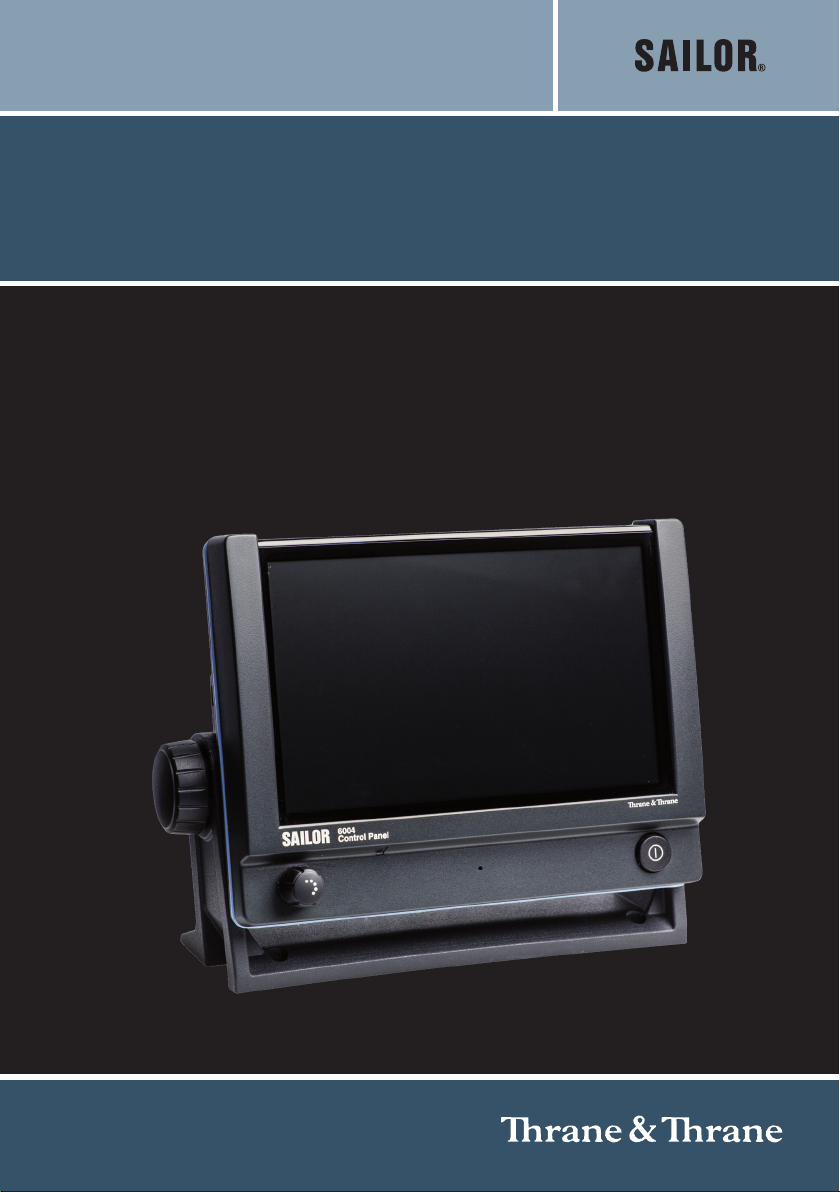
SAILOR 6004 Control Panel


SAILOR 6004
Control Panel
Installation manual
Document number: 98-136644-A
Release date: January 3, 2013

Disclaimer
Any responsibility or liability for loss or damage in connection with the use of this
product and the accompanying documentation is disclaimed by Thrane & Thrane. The
information in this manual is provided for information purposes only, is subject to
change without notice and may contain errors or inaccuracies.
Manuals issued by Thrane & Thrane are periodically revised and updated. Anyone
relying on this information should acquire the most current version e.g. from thrane.com
or from the distributor.
Thrane & Thrane is not responsible for the content or accuracy of any translations or
reproductions, in whole or in part, of this manual from any other source.
Thrane & Thrane A/S is trading as Cobham SATCOM.
Copyright
© 2013 Thrane & Thrane A/S. All rights reserved.
Trademark Acknowledgements
• Thrane & Thrane is a registered trademark of Thrane & Thrane A/S in the European
Union and the United States.
• SAILOR is a registered trademark of Thrane & Thrane A/S in the European Union, the
United States and other countries.
• Other product and company names mentioned in this manual may be trademarks or
trade names of their respective owners.
This product contains Android™ software (a Google Inc. trademark).
Safety summary 1
The following general safety precautions must be observed during all
phases of operation, service and repair of this equipment. Failure to comply
with these precautions or with specific warnings elsewhere in this manual
violates safety standards of design, manufacture and intended use of the
equipment. Thrane & Thrane assumes no liability for the customer's failure
to comply with these requirements.
DO NOT OPERATE IN AN EXPLOSIVE ATMOSPHERE
Do not operate the equipment in the presence of flammable gases or fumes.
Operation of any electrical equipment in such an environment constitutes a
definite safety hazard.
KEEP AWAY FROM LIVE CIRCUITS
Operating personnel must not remove equipment covers. Component
replacement and internal adjustment must be made by qualified
maintenance personnel. Do not service the unit with the power cable
connected. Always disconnect and discharge circuits before touching them.
DO NOT SUBSTITUTE PARTS OR MODIFY EQUIPMENT
Because of the danger of introducing additional hazards, do not substitute
parts or perform any unauthorized modification to the equipment.
COMPASS SAFE DISTANCE
Minimum compass safe distance: 0.6 m.
Warning! If the Control Panel is flush-mounted in a console with
high ambient air temperature (above 45°C), caution
shall be taken to avoid skin burns when servicing the
rear metal part of unit.
iii

About the manual 2
Intended readers
This manual is an installation for the SAILOR 6004 Control Panel.
The manual is intended primarily for installers of the system and
service personnel. Personnel installing or servicing the system
must be properly trained and authorized by Thrane & Thrane. It is
important that you observe all safety requirements listed in the
beginning of this manual, and install the Control Panel according
to the guidelines in this manual.
Manual overview
This manual has the following chapters:
• Introduction — a short description of the Control Panel.
• Installation — a description of how to unpack, store and install
the Control Panel.
• Connectors & controls — descriptions and pin-out for the
connectors, guidelines for connecting the Control Panel.
• Verification — instructions how to verify a successful
installation.
• Service & repair — a short description of how to handle
defective units.
• Technical specifications — technical specifications for the
Control Panel.
iv

Table of Contents
Chapter 1 Introduction
1.1 The SAILOR 6004 Control Panel ..................................1
1.1.1 General description .................................................... 1
1.1.2 Key features and functions ..........................................2
1.1.3 System configuration example .....................................2
Chapter 2 Installation
2.1 Unpacking .................................................................. 4
2.1.1 Initial inspection ........................................................4
2.1.2 Storage .....................................................................4
2.2 Installing the Control Panel ........................................ 5
2.2.1 Desktop mounting ..................................................... 5
2.2.2 Flush mount ..............................................................7
2.2.3 Mounting the cable relief bracket ............................... 10
Chapter 3 Connectors & controls
3.1 Connectors ................................................................ 11
3.1.1 Auxiliary connector (AUX) ......................................... 12
3.1.2 Accessories connector (ACC) ...................................... 12
3.1.3 USB connector ......................................................... 13
3.1.4 DC Power input 12—24 V DC (PWR) .............................. 14
3.1.5 LAN connector ......................................................... 16
3.2 Cabling ......................................................................17
3.2.1 Cable requirements .................................................. 17
3.2.2 Grounding ............................................................... 17
3.2.3 Connecting cables .................................................... 18
3.3 Controls .....................................................................18
3.3.1 Power button ........................................................... 18
3.3.2 Dim and night mode ................................................. 18
v

Table of Contents
Chapter 4 Verification
4.1 Overview ...................................................................19
4.2 Check of the Control Panel ........................................19
4.2.1 Running a self test ................................................... 20
4.2.2 Test log and further information ................................ 22
Chapter 5 Service & repair
5.1 General service information ..................................... 23
5.2 Maintenance & troubleshooting ............................... 23
5.3 Repacking for shipment ........................................... 24
App. A Technical specifications
Glossary
.........................................................................................27
Index ........................................................................................ 29
vi
Chapter 1
Introduction 1
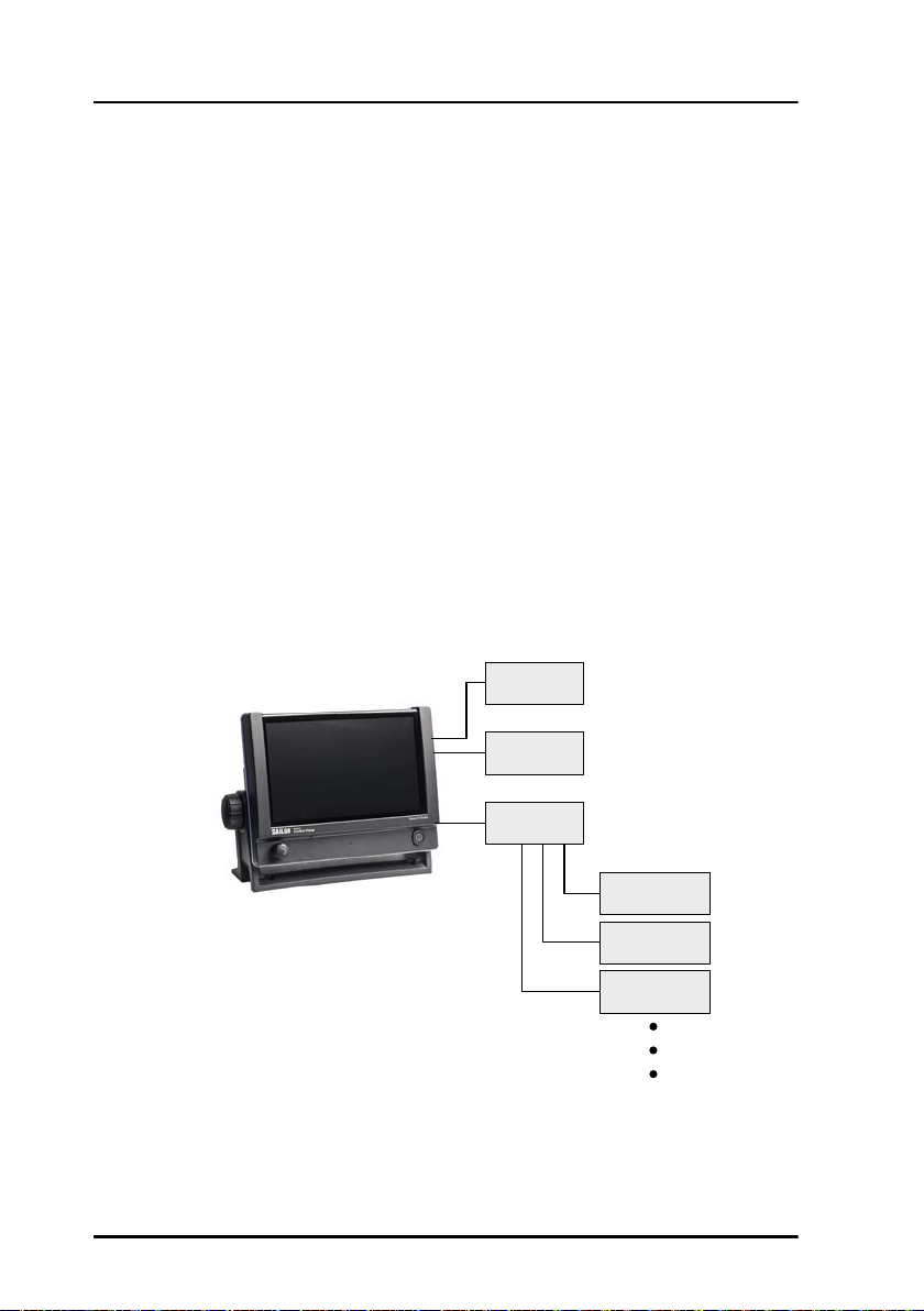
1.1 The SAILOR 6004 Control Panel
1.1.1 General description
You can use the
SAILOR 6004 Control Panel
as a generic control panel
for a number of
ThraneLINK applications.
The individual applications
are managed in separate
windows. Notifications
from the applications
assist the user in
monitoring all applications
installed.
11111
Introduction
The Control Panel has a buzzer for alarm tones. It has also an alarm output
providing 2 alarms to external equipment. The display supports night mode.
The Control Panel can be remotely switched on.
The basic configuration application for ThraneLINK is already installed in the
Control Panel upon shipping. All individual applications are installed and
updated from the attached devices (e.g. SAILOR 628x AIS, SAILOR 6390 Navtex
Receiver, SAILOR 100 Satellite TV, etc.).
1
Chapter 1: Introduction
1.1.2 Key features and functions
The Control Panel has the following key features:
• 7 inch display with touch-screen functionality
• Dual LAN (2 Ethernet connectors)
• ThraneLINK compatible
• Handling of multiple applications
• Amplifier for external speaker, e.g. SAILOR 6270 Loudspeaker
• Rear mounted USB (x2, e.g. for external keyboard)
• Connector for SAILOR 6201 Handset or similar
1.1.3 System configuration example
The following drawing shows an example of how to connect other systems to a
SAILOR 6004 Control Panel.
6$,/25
+DQGVHW
86%KRVW
(WKHUQHW
VZLWFK
2 The SAILOR 6004 Control Panel
6$,/25[
$,6
6$,/25
6DWHOOLWH79
6$,/25
1DYWH[5HFHLYHU

Chapter 2
Installation 2
This chapter provides a description of how to unpack, store and install the
Control Panel. It contains the following sections:
• Unpacking
• Installing the Control Panel
For information on cable connections see chapter 3 Connectors & controls on
page 11.
22222
Installation
3
Chapter 2: Installation
2.1 Unpacking
2.1.1 Initial inspection
Inspect the shipping carton immediately upon receipt for evidence of damage
during transport. If the shipping carton is severely damaged or water stained,
request that the carrier's agent be present when opening the carton. Save the
carton packing material for future use.
Warning! To avoid electric shock, do not apply power to the
system if there is any sign of shipping damage to any
part of the front or rear panel or the outer cover. Read
the safety summary at the front of this manual before
installing or operating the system.
After unpacking the system, inspect it thoroughly for damage and loose
components or fittings. If the contents are incomplete, if there is mechanical
damage or defect, or if the system does not work properly, notify your dealer.
2.1.2 Storage
The Control Panel may be stored or shipped in temperatures between -30° C
and +80° C. Protect the Control Panel from extreme temperature variation
which can cause condensation.
4 Unpacking
 Loading...