

Sailor 500 FleetBroadband, Sailor 250 FleetBroadband, 250 FleetBroadband Installation Manual

INSTALLATION MANUAL
SAILOR
500/250 FleetBroadband

Thrane & Thrane A/S
SAILOR
®
500 FleetBroadband
SAILOR
®
250 FleetBroadband
Installation manual
Document number: TT98-125646-C
Release date: December 13, 2007

Information in this document is subject to change without notice and does not represent
a commitment on the part of Thrane & Thrane A/S. We recommend downloading the
latest version of the manual from the Thrane & Thrane Extranet.
Copyright © 2007 Thrane & Thrane A/S. All rights reserved.
Trademark acknowledgements
• Thrane & Thrane is a registered trademark of Thrane & Thrane A/S in the European
Union and the United States.
• SAILOR is a registered trademark of Thrane & Thrane A/S in the European Union, the
United States and other countries.
• Windows and Outlook are registered trademarks of Microsoft Corporation in the
United States and other countries.
• Inmarsat is a registered trademark of International Maritime Satellite Organisation
(IMSO) and is licensed by IMSO to Inmarsat Limited and Inmarsat Ventures plc.
• Inmarsat’s product names are trademarks or registered trademarks of Inmarsat.
• Other product and company names mentioned in this manual may be trademarks or
trade names of their respective owners.
Company addresses
www.thrane.com
Denmark
Denmark
Company headquarters
Norway
Thrane & Thrane Aalborg A/S
Porsvej 2
DK-9200 Aalborg SV
Denmark
Thrane & Thrane A/S
Lundtoftegårdsvej 93 D
DK-2800 Kgs. Lyngby
Denmark
Thrane & Thrane Norway
Bergerveien 12
PO Box 91
1375 Billingstad,
Norway
USA China
Thrane & Thrane, Inc.
509 Viking Drive, Suites
K, L and M
Virginia Beach, VA 23452
USA
Thrane & Thrane Shanghai
Unit 602 - Building 4,
289 Bisheng Rd.
Zhangjiang High-tech Park,
Pudong
201204 Shanghai
P. R. China
iii
Safety summary 1
The following general safety precautions must be observed during all
phases of operation, service and repair of this equipment. Failure to comply
with these precautions or with specific warnings elsewhere in this manual
violates safety standards of design, manufacture and intended use of the
equipment. Thrane & Thrane A/S assumes no liability for the customer's
failure to comply with these requirements.
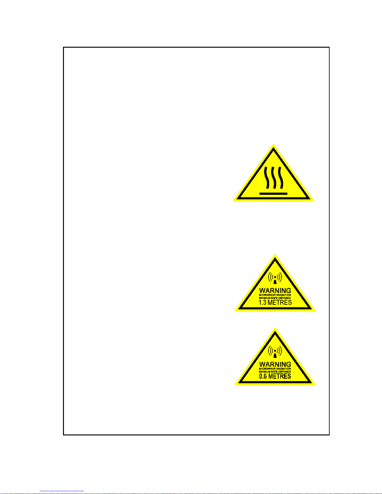
Observe marked areas
Under extreme heat conditions do not touch
areas of the terminal or antenna that are
marked with this symbol, as it may result in
injury.
Microwave radiation hazards
During transmission the antenna in this system radiates microwave power.
This radiation may be hazardous to humans close to the antenna. During
transmission, make sure that nobody gets closer than the recommended
minimum safety distance.
On the SAILOR 500 FleetBroadband, the
minimum safety distance on the focal line to
the antenna panel is 1.3 m, based on a
radiation level of 10 W/m
2
. The radiation level is
100 W/m
2
at a distance of 0.4 m from the
antenna panel. Refer to the drawing on the
next page.
On the SAILOR 250 FleetBroadband, the
minimum safety distance on the focal line to the
antenna panel is 0.6 m, based on a radiation
level of 10 W/m
2
. The radiation level is 100
W/m
2
at a distance of 0.2 m from the antenna
panel. Refer to the drawing on the next page.
iv
Distance to other equipment
Do not move the antenna closer to radars than the minimum safe distance
specified in Radar distance on page 12 - it may cause damage to the
antenna. The equipment must be installed with the following minimum safe
distances to magnetic steering compass:
SAILOR FleetBroadband terminal: min. 0.3 m.
SAILOR 500 FleetBroadband antenna: min. 1.0 m
SAILOR 250 FleetBroadband antenna: min. 1.1 m
Service
User access to the interior of the terminal is prohibited. Only a technician
authorized by Thrane & Thrane A/S may perform service - failure to comply
with this rule will void the warranty. Access to the interior of the antenna is
allowed, but only for replacement of certain modules - as described in this
manual. General service may only be performed by a technician authorized
by Thrane & Thrane A/S.
Do not service or adjust alone
Do not attempt internal service or adjustments unless another person,
capable of rendering first aid resuscitation, is present.
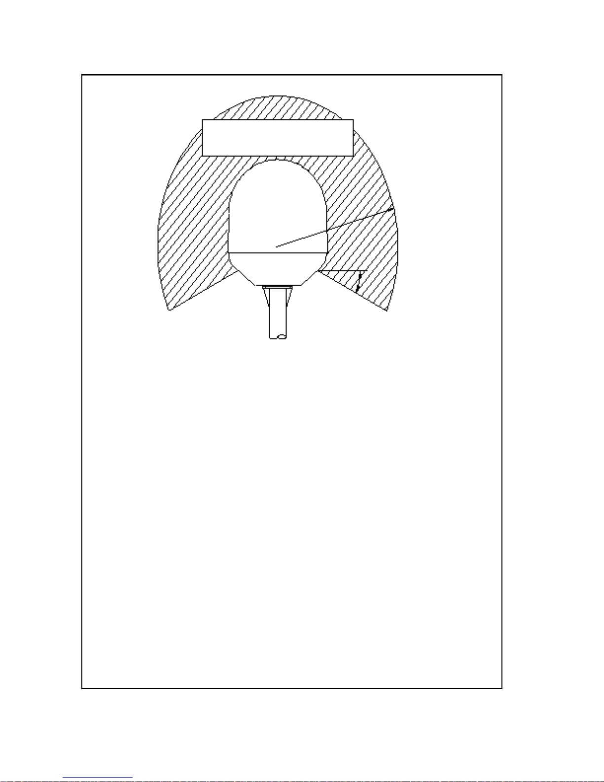
SAILOR 500:
MICROWAVE RADIATION
No personnel within safety distance
25° for SAILOR 500
60° for SAILOR 250
Safety distance:
(0.4 m, 100 W/m
2
)
1.3 m, 10 W/m
2
SAILOR 250:
(0.2 m, 100 W/m
2
)
0.6 m, 10 W/m
2

v
Grounding, cables and connections
To minimize shock hazard, the equipment chassis and cabinet must be
connected to an electrical ground. The terminal must be grounded to the
ship. For further grounding information refer to Grounding and RF
protection on page 109.
Do not extend the cables beyond the lengths specified for the equipment.
The cable between the terminal and antenna can be extended if it complies
with the specified data concerning cable losses etc.
All cables for your SAILOR FleetBroadband system are shielded and should
not be affected by magnetic fields. However, try to avoid running cables
parallel to AC wiring as it might cause malfunction of the equipment.
Power supply
The voltage range is 10.5 - 32 V DC; 14 A - 5.5 A. It is recommended that the
voltage is provided by the 24 V DC power bus on the ship. Be aware of high
start-up peak current: 20 A at 24 V, 5 ms.
If a 24 V DC power bus is not available, an external 115/230 VAC to 24 V DC
power supply can be used.
Equipment ventilation
To ensure adequate cooling of the terminal, 5 cm of unobstructed space
must be maintained around all sides of the unit (except the bottom side).
The ambient temperature range of the terminal is: -25° to +55°C.
Do not operate in an explosive atmosphere
Do not operate the equipment in the presence of flammable gases or fumes.
Operation of any electrical equipment in such an environment constitutes a
definite safety hazard.
Keep away from live circuits
Operating personnel must not remove equipment covers. Component
replacement and internal adjustment must be made by qualified
maintenance personnel. Do not replace components with the power cable
connected. Under certain conditions, dangerous voltages may exist even
with the power cable removed. To avoid injuries, always disconnect power
and discharge circuits before touching them.
Failure to comply with the rules above will void the warranty!

vi
Mandatory safety instructions to installers &
users of SAILOR
®
250 FleetBroadband 2
Use only manufacturer or dealer supplied antenna.
Antenna minimum safe distance: 0.415 m.
Antenna gain 12.2 dBi referenced to isotropic.
The Federal Communications Commission has adopted a safety
standard for human exposure to RF (Radio Frequency) energy,
which is below the OSHA (Occupational Safety and Health Act)
limits.
Antenna mounting
The antenna supplied by the manufacturer or radio dealer must
not be mounted at a location such that during radio transmission,
any person or persons can come closer than the above indicated
minimum safe distance to the antenna i.e. 0.415 m.
To comply with current FCC RF Exposure limits, the antenna must
be installed at or exceeding the minimum safe distance shown
above, and in accordance with the requirements of the antenna
manufacturer or supplier.
Base Station Installation: The antenna should be fixed-mounted
on an outdoor permanent structure. RF Exposure compliance must
be addressed at the time of installation.
Antenna substitution
Do not substitute any antenna for the one supplied or
recommended by the manufacturer or radio dealer. You may be
exposing person or persons to excess radio frequency radiation.
You may contact your radio dealer or the manufacturer for further
instructions.

vii
Warning
Maintain a separation distance from the antenna to a person(s) of
at least 0.415 m.
You, as the qualified end-user of this radio device must control the
exposure conditions of bystanders to ensure the minimum
separation distance (above) is maintained between the antenna
and nearby persons for satisfying RF Exposure compliance. The
operation of this transmitter must satisfy the requirements of
Occupational/Controlled Exposure Environment, for work-related
use. Transmit only when person(s) are at least the minimum
distance from the properly installed, externally mounted antenna.
Note
Thrane & Thrane recommends a minimum safety
distance of 0.6 m to the SAILOR 250 FleetBroadband
antenna.

viii
About the manual 3
Intended readers
This is an installation manual for the SAILOR 500 FleetBroadband
and the SAILOR 250 FleetBroadband systems. The readers of the
manual include installers of the system and service personnel.
Personnel installing or servicing the system must be properly
trained and authorized by Thrane & Thrane. It is important that
you observe all safety requirements listed in the beginning of this
manual, and install the system according to the guidelines in this
manual.
Manual overview
Note that this manual does not cover general use of the system nor
does it cover how to use the IP handset that comes with the
system. For this information, refer to the user manual for this
system and the user manual for the IP handset, both listed in the
next section.
This manual has the following chapters:
• System units contains a short description of each main unit in
the system.
• Installing the system describes where to place the system units,
how to mount them, special considerations for grounding,
distance to other equipment etc.
• Connecting power explains how to connect the terminal to
power and gives recommendations for cables.
• Hardware interfaces describes each interface on the terminal
and shows pin-out for the connectors.
• Starting up the system explains how to insert the SIM card,
power up the system and enter the PIN. It also gives a short
overview of how to use the system.
• Service and repair describes how to replace modules for
service.

ix
• Troublesho otin g describes the function of the Reset button and
the light indicators on the terminal. It also describes event
messages that may appear in the web interface.
This manual may not always reflect the latest software
functionality of your transceiver. To obtain the latest version of the
manual, please enter the Thrane & Thrane Extranet and download
the latest version, or acquire it from your distributor.
Related documents
The below list shows the documents related to this manual and to
the SAILOR 500 FleetBroadband and SAILOR 250 FleetBroadband
systems.
Title and description
Document
number
SAILOR 500 FleetBroadband
SAILOR 250 FleetBroadband
User Manual
Explains how to set up and use the
SAILOR FleetBroadband systems.
TT 98-125645
SAILOR 500/250 FleetBroadband, Quick Guide
A short guide to the most important functions
of the SAILOR FleetBroadband systems.
TT98-125647
Thrane & Thrane IP Handset, User Manual
Explains the features and functions of the
Thrane & Thrane IP handset. The IP handset
works as a standard IP handset, but also
serves as a user interface for the
SAILOR FleetBroadband systems.
TT98-126059

x
Typography
In this manual, typography is used as indicated below:
Bold is used for the following purposes:
• To emphasize words.
Example: “Do not touch the antenna”.
• To indicate what the user should select in the user interface.
Example: “Select Settings > LAN”.
Italic is used to emphasize the paragraph title in cross-
references.
Example: “For further information, see Connecting Cables on
page...”.
COURIER is used to indicate low level commands such as AT
commands.
Example: “In your terminal program, type ATD”.

xi
Table of contents
Chapter 1 System units
1.1 Introduction ............................................................... 1
1.2 Terminal .................................................................... 1
1.3 SAILOR
®
500 FleetBroadband antenna .......................2
1.4 SAILOR
®
250 FleetBroadband antenna .......................3
1.5 IP handset and cradle ................................................4
Chapter 2 Installing the system
2.1 Unpacking .................................................................7
2.2 Placing the antenna ...................................................8
2.3 Installing the antenna ...............................................21
2.4 Placing the terminal ................................................27
2.5 Installing the terminal .............................................28
Chapter 3 Connecting power
3.1 Power source ...........................................................37
3.2 Power cable selection ..............................................38
3.3 To connect power ....................................................42
3.4 Remote on/off ..........................................................43
Chapter 4 Hardware interfaces
4.1 The connector panel ................................................45
4.2 Antenna interface on terminal .................................46
4.3 DC power input ........................................................47
4.4 Ground stud .............................................................49

Table of contents
xii
4.5 Analog Phone/Fax interface .................................... 50
4.6 ISDN interface .......................................................... 51
4.7 LAN interface ...........................................................53
4.8 Discrete I/O interface ...............................................55
4.9 L-Band interface ..................................................... 58
Chapter 5 Starting up the system
5.1 Using the SIM card ...................................................59
5.2 Powering the system ................................................ 61
5.3 Entering the SIM PIN for the terminal ......................62
5.4 Operating the system ...............................................64
Chapter 6 Service and repair
6.1 Introduction .............................................................65
6.2 Replacing modules .................................................65
Chapter 7 Troubleshooting
7.1 Reset button ............................................................75
7.2 Status signaling .......................................................78
7.2.3 Logging of events .....................................................83
App. A Part numbers
A.1 System units ........................................................... 85
A.2 Spare parts, SAILOR
®
500 FleetBroadband .............. 86
A.3 Spare parts, SAILOR
®
250 FleetBroadband ...............87
A.4 Accessories ............................................................. 88

Table of contents
xiii
App. B Technical specifications
B.1 Overview ..................................................................89
B.2 SAILOR
®
500 FleetBroadband antenna .....................89
B.3 SAILOR
®
250 FleetBroadband antenna .....................95
B.4 Minimum distance to transmitters. ......................... 100
B.5 SAILOR FleetBroadband terminal ............................ 101
App. C Grounding and RF protection
C.1 Why is grounding required? ....................................109
C.2 General about marine DC systems .......................... 110
C.3 General about marine grounding ............................ 112
C.4 Grounding Recommendations ................................. 114
C.5 Alternative grounding for steel hulls ....................... 116
C.6 Alternative grounding for aluminum hulls .............. 118
C.7 Alternative grounding for fiberglass hulls ...............120
C.8 Alternative grounding for timber hulls ....................122
C.9 Separate ground cable ............................................124
C.10 RF interference .......................................................128
C.11 Electrostatic Discharge ............................................129
Glossary ........................................................................................ 131
Index ........................................................................................135

Table of contents
xiv
1
Chapter 1
1111
System units
System units 1
1.1 Introduction
The basic system consists of three units: The terminal, the antenna and the IP
handset with cradle.
There are two different types of antennas, depending on whether you have a
SAILOR 500 FleetBroadband system or a SAILOR 250 FleetBroadband system.
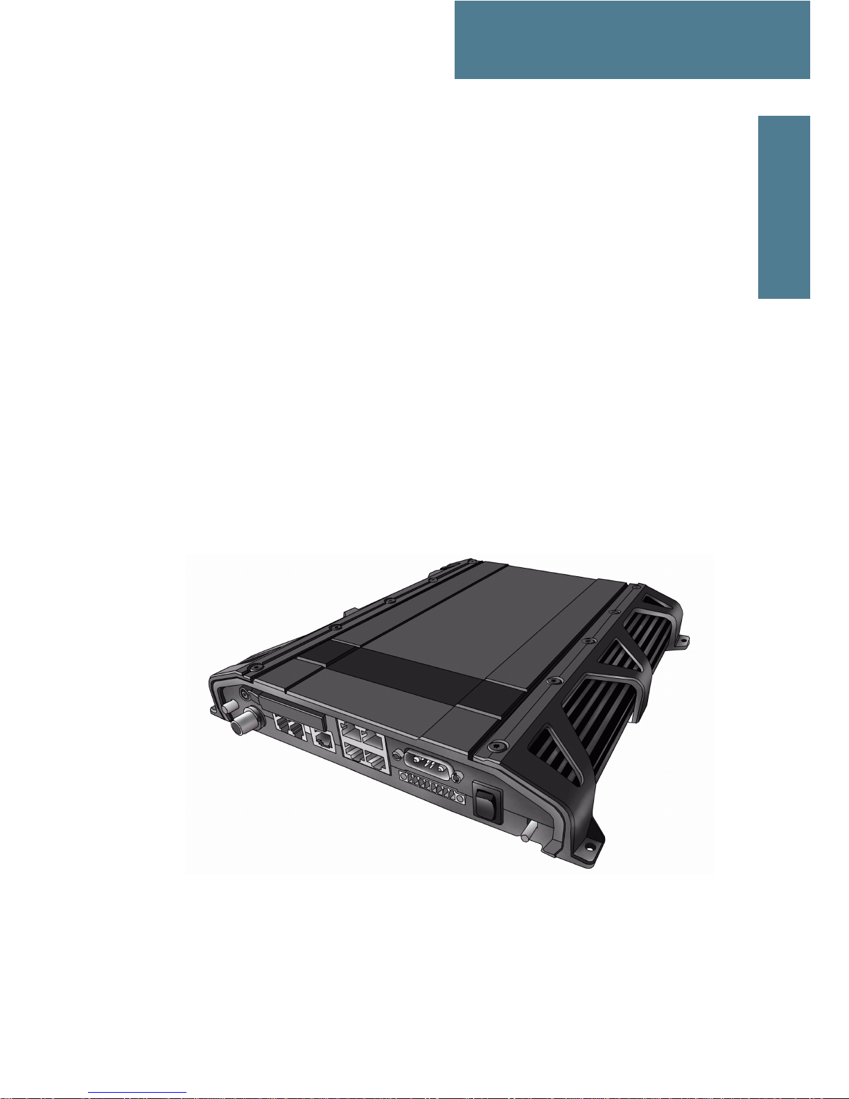
1.2 Terminal
The terminal – which contains the primary electronic parts – is designed for
wall or desktop installation.
The terminal supplies 18-29 V DC to the antenna through a single coaxial
cable.
The DC input for the terminal is designed for both 24 V DC and 12 V DC power
supply.

Chapter 1: System units
2SAILOR
®
500 FleetBroadband antenna
1.3 SAILOR®500 FleetBroadband antenna
The SAILOR 500 FleetBroadband antenna is a BGAN Class 8 mechanical
tracking antenna, consisting of a stabilized antenna with RF-unit, antenna
control unit and GPS antenna. All communication between the antenna and
terminal passes through a single coaxial cable. The antenna unit is protected
by a fibre glass radome.

Chapter 1: System units
SAILOR®250 FleetBroadband antenna 3
1111
System units
1.4 SAILOR®250 FleetBroadband antenna
The SAILOR 250 FleetBroadband antenna is a BGAN Class 9 mechanical
tracking antenna. All communication between the antenna and terminal
passes through a single coaxial cable. The antenna unit is protected by a
thermo-plastic radome.
Chapter 1: System units
4 IP handset and cradle
1.5 IP handset and cradle
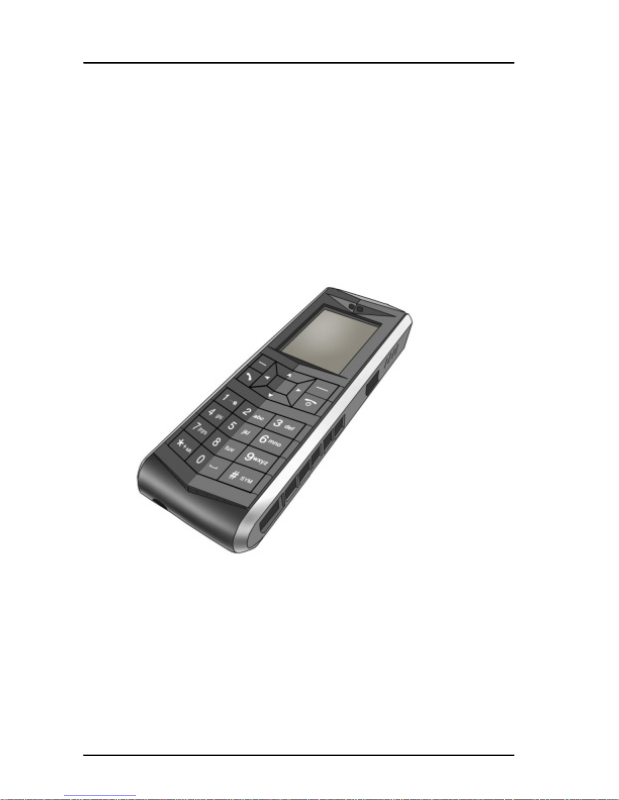
1.5.1 Thrane & Thrane IP handset
Besides the normal functions of an IP handset, the Thrane & Thrane IP
handset also provides a user interface for the SAILOR FleetBroadband system.
The IP handset connects to the LAN interface of the terminal, and is power
supplied with Power over Ethernet (PoE) through the LAN interface.
For further information on the IP handset, refer to the user manual for the
Thrane & Thrane IP handset.
Chapter 1: System units
IP handset and cradle 5
1111
System units
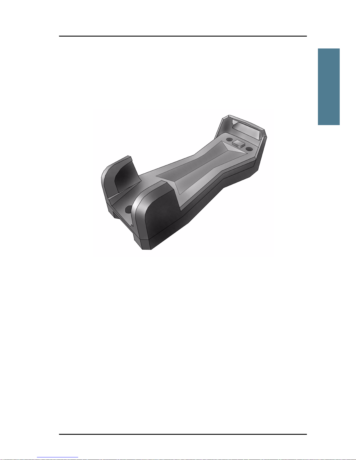
1.5.2 Thrane & Thrane IP cradle
The IP cradle serves as a holder for the IP handset. It is power supplied from
the terminal using Power over Ethernet (PoE). The cradle is connected to the
handset with a coil cord and to the terminal with a standard LAN cable.

Chapter 1: System units
6 IP handset and cradle

7
Chapter 2
2222
Installing the system
Installing the system 2
2.1 Unpacking
Unpack your SAILOR FleetBroadband system and check that the following
items are present:
• TT-3738A SAILOR FleetBroadband terminal
• TT-3052A SAILOR 500 FleetBroadband antenna or
TT-3050A SAILOR 250 FleetBroadband antenna
• TT-3670A IP handset and cradle
• Basic cable support kit
•Power cable
• Antenna cable
•LAN cable
• I/O connector
•User manual
• Installation manual (this manual)
•Quick guide
Inspect all units and parts for possible transport damage.
Note
For information on how to install the IP handset and cradle, refer to
the user manual for the handset.
Chapter 2: Installing the system
8 Placing the antenna
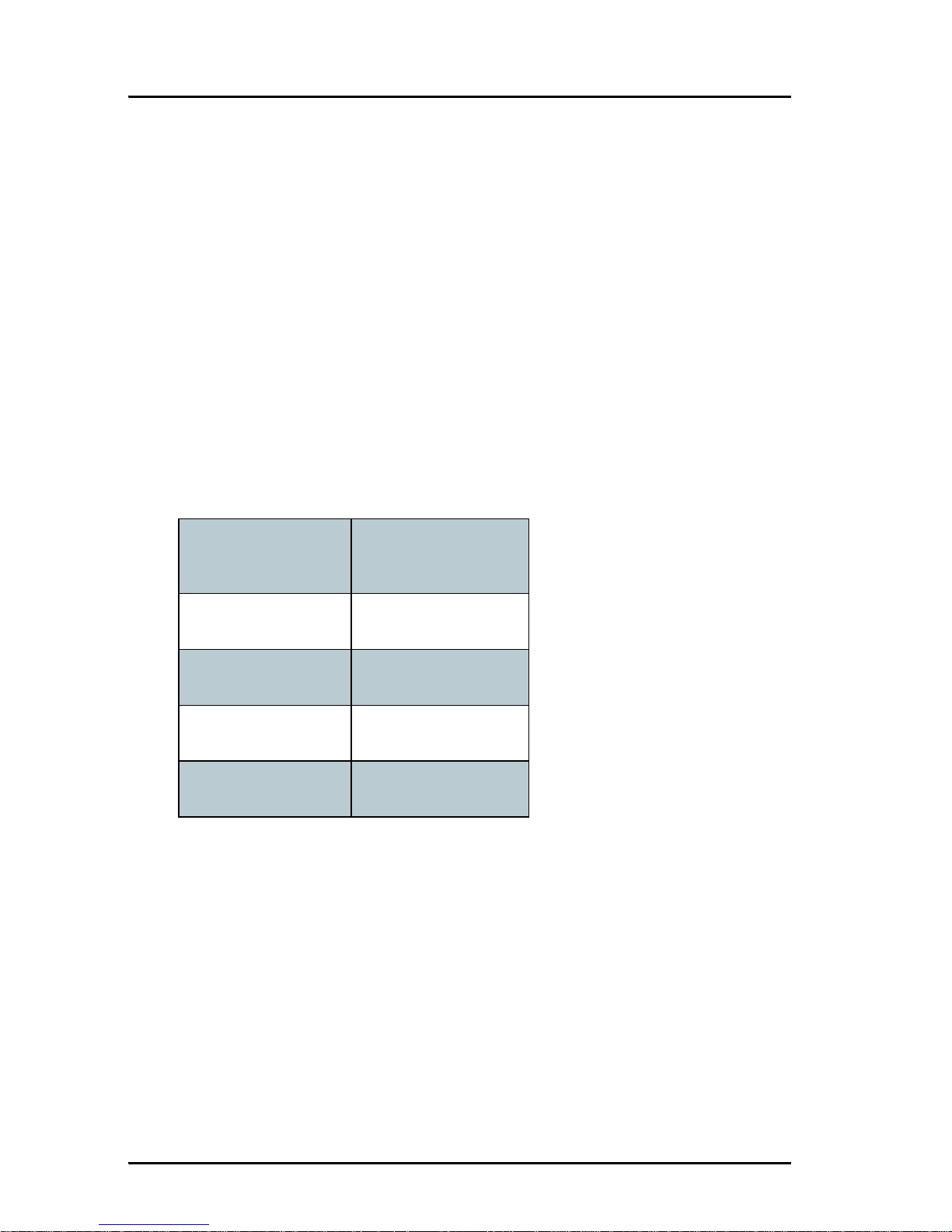
2.2 Placing the antenna
2.2.1 Obstructions
The antenna rotates 360° and down to –25° for the
SAILOR 500 FleetBroadband and -60° for the SAILOR 250 FleetBroadband in
pitch and roll, to allow for continuous pointing even in heavy sea conditions.
Any obstructions within this volume can cause signal degradation.
The amount of degradation depends on the size of the obstruction and the
distance from the antenna. As a rule of thumb any obstruction that subtends
an angle of less than 3° at the antenna has limited effect. The table below
gives a guideline for obstruction sizes, which will cause limited degradation.
Distance of
Obstruction
Size of Obstruction
3m 16cm
5m 26 cm
10 m 52 cm
20 m 104 cm
Chapter 2: Installing the system
Placing the antenna 9
2222
Installing the system
2.2.2 Radiation hazard
The SAILOR 500 FleetBroadband antenna radiates 22 dBW EIRP. This
translates to a minimum safety distance of 1.3 m from the antenna while it is
transmitting, based on a radiation level of 10 mW/cm
2
.
The SAILOR 250 FleetBroadband antenna radiates 16.1 dBW EIRP. This
translates to a minimum safety distance of 0.6 m from the antenna while it is
transmitting, based on a radiation level of 10 mW/cm
2
.
For higher radiation levels, see the table below.
Radiation
level
Distance
SAILOR 500 FleetBroadband SAILOR 250 FleetBroadband
100 W/m
2
0.4 m 0.2 m
10 W/m
2
1.3 m 0.6 m
MICROWAVE RADIATION
NO PERSONNEL
based on 10 W/m
2
SAILOR 500:
Safety distance:
1.3 m, 10 W/m
2
SAILOR 250:
0.6 m, 10 W/m
2
25° for SAILOR 500
60° for SAILOR 250

Chapter 2: Installing the system
10 Placing the antenna
2.2.3 Interference
Overview
The antenna must be mounted as far away as possible from the ship’s radar
and high power radio transmitters (including other Inmarsat based systems),
because they may compromise the antenna performance. RF emission from
radars might actually damage the antenna.
The SAILOR FleetBroadband antenna itself may also interfere with other radio
systems. Especially other Inmarsat systems and GPS receivers with poor
frequency discrimination are vulnerable to the radiation generated by the
SAILOR FleetBroadband antennas.
Chapter 2: Installing the system
Placing the antenna 11
2222
Installing the system
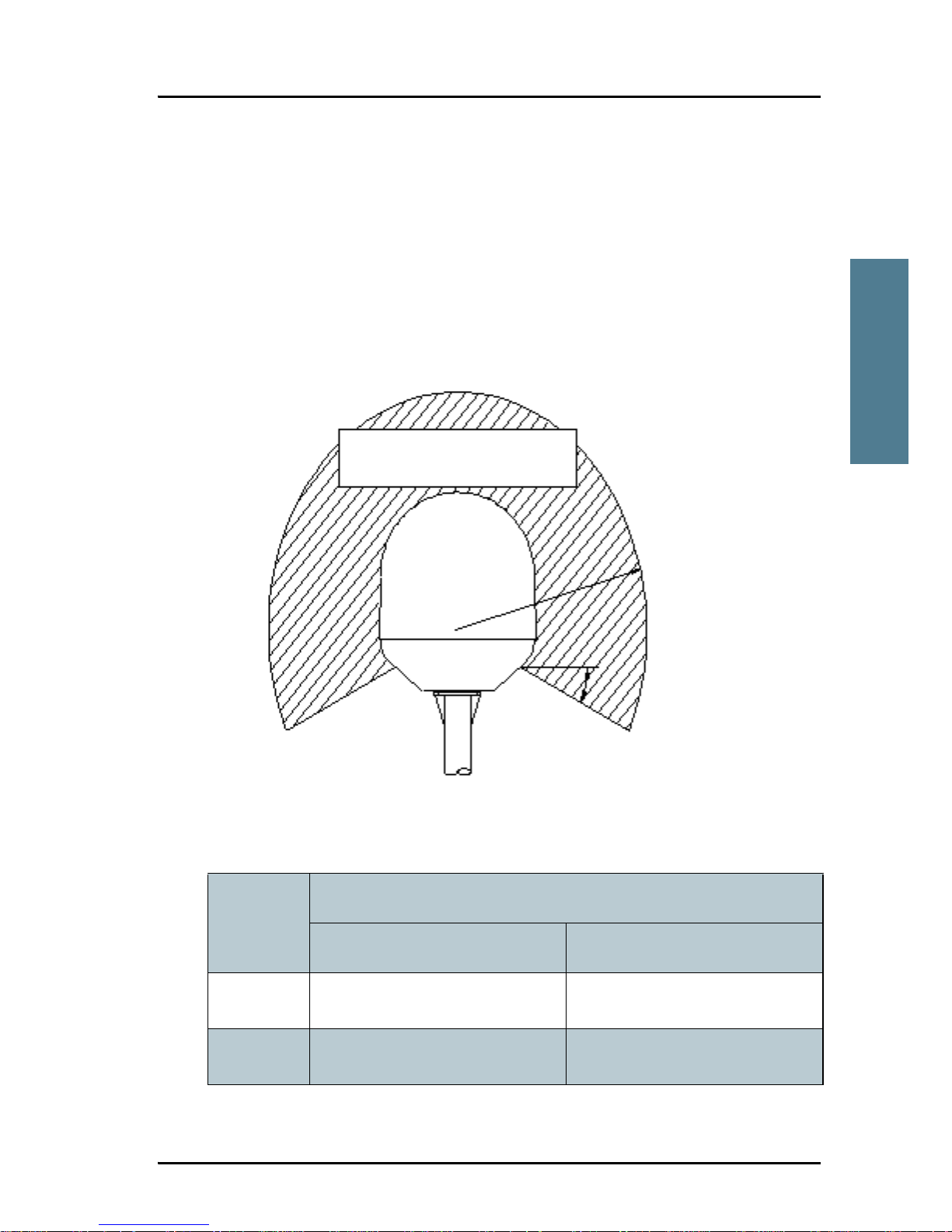
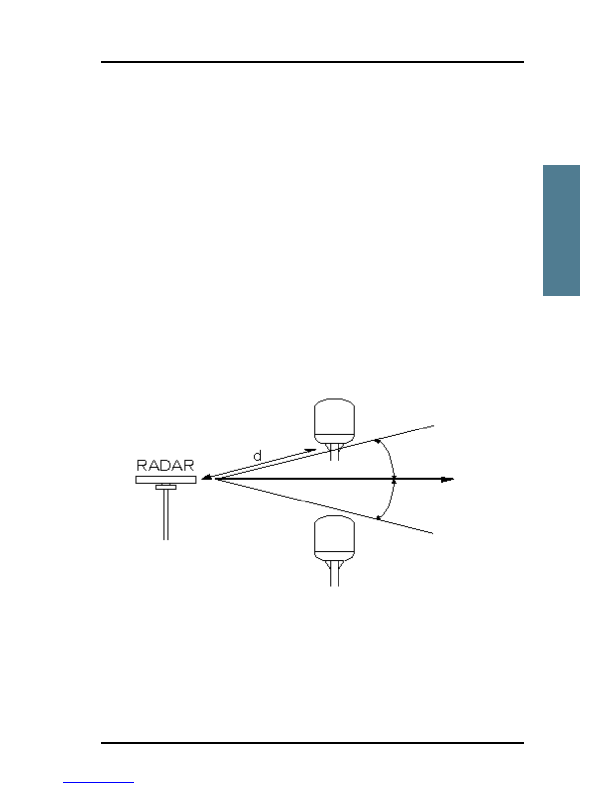
Radar
It is difficult to give exact guidelines for the minimum distance between a
radar and the antenna because radar power, radiation pattern, frequency and
pulse length/shape vary from radar to radar. Further, the antenna is typically
placed in the near field of the radar antenna and reflections from masts, decks
and other items in the vicinity of the radar are different from ship to ship.
However, it is possible to give a few guidelines:
Since a radar radiates a fan beam with a horizontal beam width of a few
degrees and a vertical beam width of up to +/- 15°, the worst interference can
be avoided by mounting the antenna at a different level – meaning that the
antenna is installed minimum 15° above or below the radar antenna. Due to
near field effects the benefit of this vertical separation could be reduced at
short distances (below approximately 10 m) between radar antenna and the
SAILOR FleetBroadband antenna. Therefore it is recommended to ensure as
much vertical separation as possible when the SAILOR FleetBroadband
antenna has to be placed close to a radar antenna.
Min. 15°
Min. 15°
Chapter 2: Installing the system
12 Placing the antenna
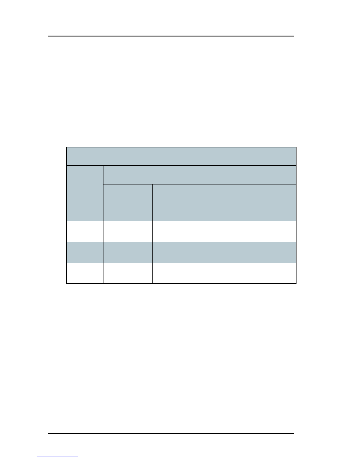
Radar distance
The minimum acceptable separation (d min.) between a radar and the
antenna is determined by the radar wavelength/frequency and the power
emitted by the radar. The tables below show some “rule of thumb” minimum
separation distances as a function of radar power at X and S band. If the d
min. separation listed below is applied, antenna damage is normally avoided.
“d min.” is defined as the shortest distance between the radar antenna (in any
position) and the surface of the SAILOR FleetBroadband antenna.
X-band (~ 3 cm / 10 GHz) damage distance
Radar
power
SAILOR 500 FleetBroadband SAILOR 250 FleetBroadband
d min. at 15°
vertical
separation
d min. at 60°
vertical
separation
d min. at 15°
vertical
separation
d min. at 60°
vertical
separation
0 – 10 kW 0.8 m 0.4 m 0.8 m 0.4 m
30 kW 2.4 m 1.2 m 2.4 m 1.2 m
50 kW 4.0 m 2.0 m 4.0 m 2.0 m

Chapter 2: Installing the system
Placing the antenna 13
2222
Installing the system
The separation distance for C-band (4-8 GHz) radars should generally be the
same as for X-band radars.
Interference
Even at distances greater than “d min.” in the previous section the radar
might still be able to degrade the performance of the SAILOR FleetBroadband
system.
The presence of one or more X-band radars within a radius up to 100 m could
cause a minor degradation of the signal-to-noise ratio during high speed and
data calls. The degradation will be most significant at high radar pulse
repetition rates.
As long as receiving conditions are favorable, this limited degradation is
without importance. However, if receiving conditions are poor – e.g. due to
objects blocking the signal path, heavy rainfall or icing, low satellite elevation
and violent ship movements – the small extra degradation due to the radar(s)
could cause poor call quality. A voice call might become noisy and perhaps fail
while a data connection might decrease in speed and performance.
S-band (~ 10 cm / 3 GHz) damage distance
Radar
power
SAILOR 500 FleetBroadband SAILOR 250 FleetBroadband
d min. at 15°
vertical
separation
d min. at 60°
vertical
separation
d min. at 30°
vertical
separation
d min. at 75°
vertical
separation
0 – 10 kW 0.4 m 0.2 m 0.4 m 0.2 m
30 kW 1.0 m 0.5 m 1.0 m 0.5 m
50 kW 2.0 m 1.0 m 2.0 m 1.0 m

Chapter 2: Installing the system
14 Placing the antenna
The presences of S-band radar(s) are unlikely to cause any performance
degradation – as long as the minimum distances (d min.) listed in the previous
section are applied.
It is strongly recommended that interference free operation is verified
experimentally before the installation is finalized.
Other Inmarsat systems
Recommended minimum safe distance to other Inmarsat antennas is 10 m.
GPS receivers
Good quality GPS receivers will work properly very close to the antenna typically down to one meter outside the main beam, and down to a few meters
inside the main beam. However, simple GPS receivers with poor frequency
discrimination could be affected at longer range (typically 10 m). It is always
recommended to test the GPS performance before the installation is finalized.
Other transmitters
See Minimum distance to transmitters. on page 100 in Appendix B for
minimum recommended distance to transmitters in the frequency range below
1000 MHz.
Other precautions
Do not place the antenna close to a funnel, as smoke deposits are corrosive.
Furthermore, deposits on the radome can degrade performance.
Caution! The antenna must never be installed closer to a radar
than “d min.” - even if experiments show that
interference free operation can be obtained at shorter
distances than “d min.” in the previous section.
 Loading...