


SAILOR
SYSTEM 4000
MF/HF 150W
Technical Manual


Please Note:
Any responsibility or liability for loss or damage in connection with the use of this product and the
accompanying documentation is disclaimed. The information in this quick guide is furnished for
informational use only, is subject to change without notice, may contain errors or inaccuracies, and
represents no commitment whatsoever. This agreement is governed by the laws of Denmark.
Doc. No.: M4500BGB0 Issue: A/0125


MF/HF 150W
CONTENTS
PAGE
1 INTRODUCTION 1-1
1.1 GENERAL DESCRIPTION 1-1
1.2 TECHNICAL DATA 1-1
2 INSTALLATION 2-1
2.1 DESCRIPTION 2-1
2.2 MOUNTING THE UNITS 2-1
2.3 GROUND CONNECTIONS 2-3
2.4 GROUNDING CONSIDERATIONS 2-3
2.5 ANTENNAS 2-5
2.6 POWER SUPPLY 2-8
2.7 INTERCONNECTION OF UNITS 2-8
2.8 CONNECTOR MOUNTING INSTRUCTIONS 2-13
2.9 POSITION AND TIME INFORMATION 2-14
2.10 OPTIONS MENU - SETTING UP THE SYSTEM 2-14
2.11 DSC PROGRAMMING 2-15
2.12 BATTERY ALARM ADJUSTMENT 2-16
2.13 FACTORY RESETTING 2-16
2.14 FINAL INSTALLATION CHECK 2-16
3 TECHNICAL DESCRIPTION 3-1
3.1 CONTROL UNIT 3-1
3.2 TRANSCEIVER UNIT 3-1
3.3 CONTROL / INTERCON MODULE 636510 3-1
3.4 SYNTH. AND DSC WR MODULE 636511 3-1
3.5 RX/EX SIGNAL PATH MODULE 636515 3-2
3.6 PA AND FILTERS MODULE 636520 3-2
3.7 SMPS MODULE 636530 3-2
3.8 TRANSCEIVER UNIT BLOCK DIAGRAM 3-3
3.9 TRANSCEIVER UNIT INTERCONNECTION DIAGRAM 3-4
3.10 ANTENNA TUNING UNIT 3-5
3.11 ANTENNA TUNING UNIT BLOCK DIAGRAM 3-5
3.12 POWER CONTROL AND PROTECTION SYSTEM 3-6
3.13 POWER CONTROL AND PROTECTION SYSTEM 3-7
4 SERVICE 4-1
4.1 PREVENTIVE MAINTENANCE 4-1
4.2 REALIGNMENT OF MASTER OSCILLATOR 4-1
4.3 SOFTWARE UPDATE 4-2
4.4 TROUBLE SHOOTING 4-2
4.5 POWER PROTECTION 4-3
4.6 SELF TEST 4-5
5 SPARE PART EXCHANGE 5-1
5.1 DISASSEMBLING THE TRANSCEIVER UNIT 5-1
5.2 TRANSCEIVER UNIT MODULE LOCATION 5-2
0125


MF/HF 150W
CONTENTS
1 INTRODUCTION 1-1
1.1 GENERAL DESCRIPTION 1-1
1.2 TECHNICAL DATA 1-1
0125


MF/HF 150W
1 INTRODUCTION
1.1 GENERAL DESCRIPTION
The 150 W MF/HF transceiver with integrated DSC is designed for maritime applications in voluntary as
well as compulsorily fitted vessels. It offers simplex and semi-duplex SSB radiotelephone communication
in the maritime mobile frequency bands between 1.6 and 30 MHz. With the built-in DSC modem and the
2187.5 kHz DSC watch receiver the equipment forms an ideal system for MF GMDSS installations.
The equipment consists of a compact transceiver control unit, a fully remote controlled transceiver unit
and an automatic antenna tuning unit.
The microprocessor controlled Antenna Tuning Unit automatically matches the impedance of antennas
between 8 and 18 metres in length and requires no presetting at the installation. The typical tuning time
is 1 s. It is designed for outdoor installation and may be located up to 100 metres from the Transceiver
Unit.
The Transceiver Unit contains all receiver and transmitter circuitry. The fully protected solid state 150 W
power amplifier cooled by natural convection matches a 50 ohms antenna system, but is normally used
in connection with the Antenna Tuning Unit. The DSC modem contains two demodulators, one connected
to the built-in watch receiver for continuous watch on the DSC distress frequency 2187.5 kHz, the other
connected to the communication receiver which may be used to keep simultaneous watch on other DSC
frequencies.
The Control Unit is for operation of radiotelephone as well as DSC functions. Use of the equipment is
simple, logic and straight forward. DSC operation is based on the use of soft keys. Guiding texts are
provided and the large display is able to show the contents of a complete call in one screen.
The equipment is designed for operation from a 24 V battery. With the optional AC Power Supply unit
installed the equipment may be supplied from 115/230 V AC main or emergency supplies with automatic
switch-over to 24 V DC supply in the absence of AC supply voltage. Also optionally battery charger for
AC is available in the product serie.
The built-in test facilities and easy-to-replace module design of the equipment simplifies the service
concept.
1.2 TECHNICAL DATA
150 W MF/HF SSB Radiotelephone with integrated DSC facility and 2187.5 kHz DSC Watch Receiver.
GENERAL
Complies with the relevant IMO performance standards, the ITU Radio Regulations, the ITU-R
recommendations and meets the relevant performance specifications of ETSI and IEC.
Operating modes: Simplex and semi-duplex SSB telephony (J3E) and DSC (J2B),
AM broadcast reception (A3E).
Frequency selection: Direct by keyboard or programmed channels.
Displayed frequency: Operating modes SSB telephony (J3E) and AM reception (A3E): Carrier
frequency.
Operating mode DSC (J2B): Up-converted sub-carrier frequency.
Frequency stability: 0.35 ppm.
Ageing: Less than 1 ppm/year.
Warm-up time: Less than one minute.
Pre-programmed channels: 289 ITU HF telephony channels,
54 ITU MF telephony channels in Region I,
40 ITU DSC frequency pairs.
User programmable
channels: 199 frequency pairs with mode (1-199).
User programmable
stations: 40 stations with name, MMSI and station channels.
0125
1-1

1 INTRODUCTION MF/HF 150W
User programmable
station channels: 400 frequency pairs with mode, channel number and type.
Scanning: DSC Watch: up to 6 DSC frequencies,
Telephony Watch: up to 10 telephony channels,
Multi Watch: one DSC frequency + up to 10 telephony channels.
Dual Watch: one DSC frequency + current telephony frequency,
Other facilities: Built-in self test programme. Continuously operating power and protec-
tion monitor.
Supply voltage: 21.6 to 31.2 V DC.
With optional external AC Power Supply: 115/230 V AC, 50/60 Hz.
Automatic change-over to DC in the absence of AC supply.
Power consumption: (approx. at 24 V DC)
RX, 60 W,
TX, SSB unmodulated: 100 W,
TX, SSB speech: 175 W,
TX, SSB two-tone: 300 W,
TX, DSC: 420 W.
Operating temperature
range: -20 deg. C to +55 deg. C.
Equipment category: Control Unit: Protected,
Transceiver Unit: Protected,
Antenna Tuning Unit: Exposed.
Compass safe distance: Compass safe distance in accordance with ISO/R 694 are given below
in metres.
Unit Standard Steering
5.4°/H 18°/H
Transceiver Unit 0.4 0.2
Antenna Tuning Unit 0.3 0.1
For Control Unit please refer to Operator’s Manual.
DIMENSIONS AND WEIGHTS
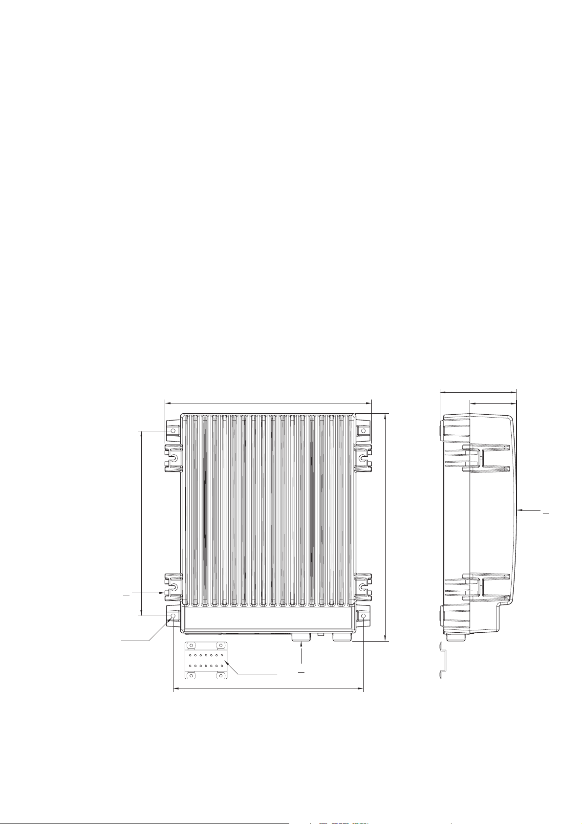
Transceiver Unit: Width: 390 mm
Height: 445 mm
Depth: 127 mm
Weight: 17.5 kg
Antenna Tuning Unit: Width: 290 mm
Height: 500 mm
Depth: 80 mm
Weight: 3.3 kg
1-2
For Control Unit please refer to Operator’s Manual.
0125

1 INTRODUCTION MF/HF 150W
RECEIVER CHARACTERISTICS
Frequency range: 150 kHz to 30 MHz.
Frequency resolution: 100 Hz by keyboard entry. 10 Hz, 100 Hz or 1 kHz search/fine-tune
facility.
Antenna impedance: 50 Ohms. Matched by the antenna amplifier in the antenna tuning unit.
Input protection: 30 V RMS (EMF).
IF selectivity: SSB telephony: 350 Hz to 2700 Hz,
AM broadcast: +/- 3 kHz,
DSC: +/- 150 Hz.
Sensitivity: Antenna input for 10 dB SINAD, 50 ohm antenna.
SSB telephony: 0.7 uV,
AM broadcast: 4 uV,
DSC: 0.3 uV.
Out-of-band intermodulation: Two 92 dBuV signals more than 30 kHz off tune produces less output
than an equivalent input signal of 30 dBuV.
In-band intermodulation: Less than -40 dB.
Cross modulation: Unwanted signal of 104 dBuV / 30 % - 400 Hz more than 20 kHz offset
from receiver frequency produces cross modulation less than - 30 dB
relative to wanted signal of 60 dBuV (SSB).
Blocking: With a wanted signal of 60 dBuV, an un-wanted signal 20 kHz off tune
110 dBuV will affect the output level by less than 3 dB or cause less than
6 dB reduction in SINAD (SSB).
Reciprocal mixing: With a wanted signal giving 20 dB SINAD, an unwanted signal 20 kHz
off tune and 80 dB above the wanted signal will cause less than 6 dB
reduction in SINAD (SSB).
Image rejection: Greater than 80 dB.
IF rejection: Greater than 80 dB.
Spurious rejection: Greater than 80 dB.
Spurious emissions: Less than 2 nW/50 ohm at antenna connector.
Audio output power: 5 W with less than 10 % distortion.
0125
1-3

1 INTRODUCTION MF/HF 150W
TRANSMITTER CHARACTERISTICS
Output power: 150 W PEP +/- 1.4 dB into 50 ohm at 24 V supply voltage.
Power reduction: Low power: approx. 20 W PEP.
Frequency range: ITU marine bands 1605 kHz to 30 MHz.
Frequency resolution: 100 Hz.
Intermodulation: Better than -31 dB/PEP in standard two-tone test.
Hum and noise: Less than - 50 dB/PEP.
Spurious emissions: Less than -43 dB/PEP, typically better than –60 dB/PEP.
Suppression of unwanted
sideband: Greater than 60 dB PEP (1 kHz, SSB).
DSC MODEM CHARACTERISTICS
Equipment class: Class B
Protocols: ITU-R M.493, M.541, and M.1082.
Type of calls: Distress alert calls, distress relay calls, distress acknowledgement calls,
all ships calls, individual station calls including polling and ship position
request calls, direct dial semi-automatic/automatic service calls.
DSC message log: Stores the 20 last received distress calls.
Stores the 20 last received non-distress calls.
Stores the 20 last transmitted calls.
Received calls are erased 48 hours after their reception.
User programmable
address book: Stores 16 calls prepared for transmission.
DSC WATCH RECEIVER CHARACTERISTICS
Frequency: 2187.5 kHz, continuous watch.
Antenna impedance: 50 ohms.
Calling sensitivity: Antenna input for symbol error rate below 1x10
-2
: 1 uV.
Adjacent channel selectivity: With a wanted signal 20 dBuV, an unwanted signal 500 Hz off tune 60
dBuV does not deteriorate the symbol error rate below 1x10
-2
.
Co-channel rejection: With a wanted signal 20 dBuV, an unwanted signal on the same
frequency 14 dBuV does not deteriorate the symbol error rate below
-2
1x10
.
RF intermodulation
response: With a wanted signal 20 dBuV, two unwanted signals more than 30 kHz
off tune 70 dBuV does not deteriorate the symbol error rate below
-2
1x10
.
1-4
0125

1 INTRODUCTION MF/HF 150W
Interference rejection and
blocking immunity: With a wanted signal 20 dBuV, an unwanted signal in the frequency
range 100 kHz to 2 GHz except a +/- 3 kHz band around the tuned
frequency 90 dBuV does not deteriorate the symbol error rate below
-2
1x10
.
Dynamic range: With a wanted signal between 80 dBuV and 0 dBuV the symbol error rate
is below 1x10
-2
.
Conducted spurious
emissions: Less than 2 nW/50 ohm at antenna connector.
Input protection: 30 V RMS (EMF).
Active antenna supply: 12 V DC, 20 mA available on DSC RX antenna connector, coax inner
connector positive.
Short circuit current max 2 mA.
ANTENNA TUNING UNIT
Frequency range: 1.6 - 30 MHz.
Antenna requirements: 8 - 18 m wire and/or whip antenna.
Antenna tuning: Fully automatic with no presetting.
Tuning speed: 0.5 - 8 s.
Input impedance: Nominal 50 ohms.
Power handling capability: 150 W PEP.
INTERFACES FOR EXTERNAL EQUIPMENT
Control Unit connectors
AUX:
NMEA: Position and time information input: NMEA 0183, RMC, GLL, GGA, ZDA
Alarm Panel: SparcBus interface for optional distress alarm panel.
SW download: PC interface for update of CU, TU or ATU software.
External speaker: AF output for external 4 to 8 ohms loudspeaker.
Transceiver unit connectors
SYS:
Remote control: RS-232 interface for control of frequency, mode and power level.
Transmitter AF line interface.
Receiver AF line interface.
External key input.
Transmitter inhibition: Input for external inhibition of transmission.
0125
Transmitter keyed
indication: Output for external indication of transmission.
1-5

1 INTRODUCTION MF/HF 150W
SUPPLY ALARM:
Battery alarm: Voltage input for high/low battery voltage alarm.
Alarm in case of
- Battery voltage too low (adjustable 22-24 V).
- Battery voltage too high (adjustable 27-32 V).
Factory preset to 23.5 V and 29.5 V.
AC alarm: Input for supply failure alarm.
Alarm when connected to GND.
1-6
0125

MF/HF 150W
CONTENTS
2 INSTALLATION 2-1
2.1 DESCRIPTION 2-1
2.2 MOUNTING THE UNITS 2-1
2.3 GROUND CONNECTIONS 2-3
2.4 GROUNDING CONSIDERATIONS 2-3
2.5 ANTENNAS 2-5
2.6 POWER SUPPLY 2-8
2.7 INTERCONNECTION OF UNITS 2-8
2.8 CONNECTOR MOUNTING INSTRUCTIONS 2-13
2.9 POSITION AND TIME INFORMATION 2-14
2.10 OPTIONS MENU - SETTING UP THE SYSTEM 2-14
2.11 DSC PROGRAMMING 2-15
2.12 BATTERY ALARM ADJUSTMENT 2-16
2.13 FACTORY RESETTING 2-16
2.14 FINAL INSTALLATION CHECK 2-16
0125

MF/HF 150W
2 INSTALLATION
2.1 DESCRIPTION
Correct installation of the equipment is important for maximum performance and reliability. Antennas and
earth connections must be installed with the greatest care using corrosion resistant materials.
Cable routing shall be made so the cables are protected from physical damage. Sharp cable bends
especially on coaxial cables must be avoided and a sufficient number of clips or straps should be used
to secure the cables.
2.2 MOUNTING THE UNITS
Mounting the Control Unit (CU)
One Unit shall be connected to the Transceiver Unit using the build-in local area network (ScanBus). The
CU may be mounted up to 100m from the Transceiver Unit using just one Multicable 5 x 2 x 0.5 mm
screened.
For detailed installation and mounting of CU - see Operator's Manual.
Mounting the Transceiver Unit (TU)
The Transceiver Unit should be installed in a dry place and consideration should be given to accessibility
for servicing. It is important to provide sufficient airspace below, above and in front of the unit for adequate
air circulation through the cooling fins. The drawing below shows the outer dimensions, mounting
possibilities and the minimum distance to other objects, as well as a drilling plan.
2
1
4 x ø8
37955A
350
391
Cable fitting
360
145
88
2
430
1
1) Space for cable: min. 150 mm
2) Space for airflow and service: min. 500 mm
Dimensions are in mm
0125
2-1

2 INSTALLATION MF/HF 150W
Mounting the Antenna Tuning Unit (ATU)
The Antenna Tuning Unit may be mounted up to 100 metres from the Transceiver Unit using just one RG213/U coaxial cable. The unit should be installed near the antenna feed point.
80
290
200
1)
76.5
75
145
3)
271
6 x ø6.50
164
164
12
2)
352
170
50
37978
1) Space to nearest overhang: min. 50 mm
2) Space for service access: min. 500 mm
3) Space for cable and service access: min. 200 mm
Dimensions are in mm
2-2
Mounting Options
0125

2 INSTALLATION MF/HF 150W
ATU
TU
CU
'Hot' Handset
RF current loop
Ground-Plane
Not OK installation
Zg
37867
11mm
ø5.4mm
crimp
wire
37836
2.3 GROUND CONNECTIONS
Antenna Tuning Unit
As the earth connection of a transmitter is a very important part of the antenna system, it is of the utmost
importance to keep in mind that the earth connection of
the Antenna Tuning Unit must have the lowest possible
RF-impedance. Losses in the earth connection will result
in a decrease in radiated power which means that the
range of the transmitter will be reduced. In steel ships a
100 x 0.5 mm copper strap as short as possible is
connected between the earth terminal at the bottom of
80
the Antenna Tuning Unit and two or three 1/2" or M12
bolts welded to the superstructure. Vessels constructed
of non-conducting materials must be equipped with a
copper earth plate having a minimum area of 1 square
50
6.6
20
metre mounted below the water line. From a copper
earth bolt hard soldered to the earth plate a 100 x 0.5 mm
copper strap is run, preferably uninterrupted to the earth
37872
6
terminal at the bottom of the Antenna Tuning Unit.
Should it be necessary to break the copper strap, for example to pass through a deck, two or three 1/2"
or M12 bolts should be used for this feed through. On wooden ships having a superstructure of metal,
this superstructure should also be effectively connected to the copper strap by using stainless steel bolts
and preferably pieces of stainless steel strips between the metal parts. On fibre glass boats, such as
yachts and sailing boats, it may be difficult to install a sufficiently good earth. Short copper straps are
bolted to conducting parts on the engine, the keel and other conducting objects. Many copper straps can
be glued to the inner surface of the hull below the water line to produce a large capacitance to the water.
It is important that the total area of copper is large and that the distance between the copper surface and
the water is as small as possible. The copper straps are connected directly to the ATU.
Copper strap 100 x 0.5mm
R3.3
Dimensions are in mm.
0125
Transceiver Unit and Control Unit
The Transceiver Unit is preferably grounded
separately to the ships metal in the shortest
possible way. A 10 to 16mm sq. ground wire is
connected to the ground terminal (cable clamp)
at the bottom of the unit.
2.4 GROUNDING CONSIDERATIONS
Proper system grounding is one of the most important installation details.
Two areas of grounding must be considered:
a) The ground connection between the ATU and earth ground plane.
b) The ground connection of the TU and the externally connected equipment.
Each area requires separate considerations
even though they are interrelated. Ideally the
Control Unit, Transceiver Unit, Antenna Tuning
Unit and the antenna ground-plane must have
the same RF ground potential. Unfortunately
this situation is seldom achieved, but interference problems will be reduced along with how
close to this “ideal” the grounding of the installation is performed.
On some installations ground loops will cause
problems. A ground loop is caused by more
than one ground path for a given unit. This will
introduce circulating RF currents which may
cause malfunction of other equipment onboard
the ship as well as a “hot” handset.
2-3

2 INSTALLATION MF/HF 150W
Antenna start
The vertical antenna always start at its electrical ground-plane, whether or not it is physically mounted
there. First determine the antenna’s electrical ground-plane, which is where the ATU must be mounted.
Where possible always take the ATU to the ground, not the ground to the ATU.
In case of a fiberglass boat, the ground-plane may well be at the hull grounding terminal. Then this is where
the Antenna Tuning Unit should go and this is where the antenna actually starts.
OK installation
Not a 'Hot' Handset
TU
CU
ATU
Ground-Plane
The antenna starts here
37868
RF ground loop
It is not always possible or practical to mount the ATU using a very short strap to the actual ground-plane.
In such a case the coaxialcable may be connected between units with different ground potentials causing
RF loop-current to flow.
Not OK installation
TU
CU
Vg = Iant x Zg
37869
Zg
ATU
coaxial cable
RF current loop
Ground-Plane
Minimizing ground loops
By routing the coax cable very close together with the ATU ground strap (secure good RF coupling
between the two) all the way down to the ground-plane, there will be no RF ground loop left to generate
the interference.
OK installation
2-4
Vg = Iant x Zg
37870
Zg
ATU
coaxial cable
Ground-Plane
TU
CU
0125

2 INSTALLATION MF/HF 150W
2.5 ANTENNAS
Transceiver Antenna
The equipment is used with common transmitting and receiving antenna. The antenna should be erected
in the open, away from conducting object such as derricks etc. which may cause reduction of the radiated
power. Insulators should be of the best type having low leakage even when wet. Stays, wires, steel masts
etc. should be either effectively earthed or insulated. The antenna should also be kept as far away as
possible from electrical equipment in order to minimize noise. Electrical installation such as cable braiding
(screens) and instruments in the vicinity of the antenna should be earthed effectively, and the instruments
in question should be fitted with noise-interference suppression devices, effective in the range 0.1 MHz
to 30 MHz to avoid malfunction of these instruments. The Antenna Tuning Unit will tune on any frequency
in the range 1.6 to 27 MHz to good whip and/or wire installations of 12 to 18 meters total electrical length.
Shorter antennas, electrical length down to 8 meters can be used. Where possible long antennas should
be installed to maximize the radiated power in the lower frequency bands.
In general a 12 meter antenna installation can be made using an 8 meter whip and 4.5 meter feeder or
a 10 meter whip and 2.5 meter feeder. In both cases the whip should be mounted on a pole allowing for
the feeder to be erected at an angle of no less than 60 degrees to create a vertical antenna system. Using
horizontal feeders or feeders mounted at an angle below 45 degrees usually transform the antenna
radiation resistance to a lower value reducing the radiated power. Furthermore, the total antenna system
should be kept well away from conductive objects such as the mast. Usually a horizontal distance of more
than 4 meters will create good results.
Note: If a whip antenna is used this should have an anti-corona ball as a top termination to prevent
crackling noise in the receiver.
The antenna is terminated at the insulator at the top of the
Antenna Tuning Unit. The insulator must be relieved from
mechanical stress by using max. 1 metre flexible wire
between the insulator and a support. To maximize the
radiated power and avoid flash over keep distance to metal
parts as long as possible. All wire junctions in the antenna
system must be made with cable lugs of correct size
according to the wire gauge. This will prevent bad connections due to corrosion. For further corrosion proofing grease
may be applied to the cable joints.
0125
2-5

2 INSTALLATION MF/HF 150W
Recommended ATU installation
On a metal-hull vessel. Mount the Antenna Tuning Unit on a custom-built bracket made from iron angle
bars (refer to figure on previous page).
Antenna Tuning Unit bracket Antenna Tuning Unit bracket
welded to the railing. welded to the deck.
2-6
0125

2 INSTALLATION MF/HF 150W
Optional an ATU Mounting Kit may be supplied as shown below. The kit exists in two versions:
1 Includes mounting plate and fittings for mast. Part no. 737589
2 Includes the mounting plate. Part no. 737588
1 For mounting the ATU directly on a mast, where the Mounting Plate and fittings for mast can form
a sufficient earth connection on a steel mast welded to the superstructure.
2 To get an even mounting surface on an uneven support.
1
2
3 4 5
6 x mountingholes for Antenna Tuner Unit.
5
Treadrod M10
64.005
1 Nut M10
2 Tooth lock washer M10
3 Fitting for mast
4 Mountingplate for ATU
5 Treadrod M10
DSC watch receiver antenna
The DSC watch receiver antenna may be an active or a passive type.
The antenna should be erected well in the clear and kept away as far as possible from electrical
equipment in order to minimize noise. Electrical installation such as cable braiding and instruments in the
vicinity of the antenna should be earthed effectively, and the instruments in question should be fitted with
noise-interference suppression devices, effective in the range 0.1 to 30 MHz. The antenna feed-in should
be coaxial cable.
In case of a passive antenna the feed-in should be as short as possible, especially in the case of short
antennas. The recommended antenna length is 7-30 meters. If a long coax cable is necessary an
impedance matching transformer should be inserted at the antenna or an active antenna should be used.
DC supply voltage for an active antenna is available at the DSC RX antenna connector. The supply
voltage is +12 V for supply currents up to 20 mA. The short circuit current is limited to 2 mA to allow passive
antennas with matching transformers to be connected directly.
0125
2-7

2 INSTALLATION MF/HF 150W
2.6 POWER SUPPLY
The supply leads are connected to the supply terminal strip of the Transceiver Unit. The supply terminal
strip is adapted for screened power supply cable to meet EMC requirements. The screen of the cable is
connected to the left terminal.
The earth connection of the equipment will not cause the battery to be earthed. Maximum permissible
peak voltage between the battery terminals and earth is 100 V. Note that fuses must be provided in the
supply leads. Table below shows the necessary cable cross sections and external fuse ratings.
15mm
screen (twisted)
conductor (twisted)
37835
60mm
plastic cover
screw
clamp
cable fitting
plastic house
Max. cable length to Recommended cable Ex ternal fuses
battery * Screened multiwire
7 m 2 x 10 mm2 40 A
11 m 2 x 16 mm2 50 A
17 m 2 x 25 mm2 63 A
2.7 INTERCONNECTION OF UNITS
Transceiver Unit connector panel
+
-
SCANBUS
1
SYS
1
24 V DC
37849
For Control Unit connector panel please refer to Operator’s Manual.
Cable 1: Handset - Control Unit
Cable: Supplied with handset
SUPPLY ALARM
1
DSC RX
RX/TX
Control Unit
‘HANDSET’ Designation Remarks
Dsub 9
1 TLF Handset earpiece
2 GND System ground
3 GND System ground
4 MIC Handset microphone
5 P TT Trans m it k ey
6 HOOK Low when on hook
7 +5V 5 V supply to handset
8 nc No connect ion
9 2182 SEL OC output. Low when 2182 kHz is
selected
2-8
0125

2 INSTALLATION MF/HF 150W
Cable 2: Control Unit - Ground
Recommended wire dimension: min. 2.5 mm
2
Maximum length 0.2 m
Cable 3: Control Unit - Transceiver Unit
Cable: Multicable 5 x 2 x 0.5 mm
2
screened
Twisted pairs: 2 and 3, 4 and 5, 8 and 9.
Maximum cable length 100 m
Cable-connector: 9 way Dsub male. Part no. 75100064
Control Unit Transceiver
‘SCANBUS’ ‘SCANBUS’ Designation Remarks
Dsub 9 Ds ub 9
1 1 SUPPLY ON Supply on signal to t he Transceiver Unit. Active when connected to GND
2 2 DATA+ Data communication between units. CAN bus. Baud rate: 125 kbps
3 3 DATA- Spec.: ISO/DIS 11898.
4 4 AF + TX AF modulation
5 5 AF - Vnom = 0.775 Vrms diff.
Vmax = 12 Vpp diff.
6 6 GND System ground
7 7 +24 V Supply voltage for the Control Unit.
8 8 RX AF + RX AF signal
9 9 RX AF - Vnom = 0.775 Vrms diff.
Vmax = 12 Vpp diff.
Shield Shield Sc reen Screen connected to syst em ground
Cable 4: Transceiver Unit - Antenna Tuning Unit
Cable: 50 ohm coaxial cable RG213/U part no.: 77.508
Maximum cable length 100 m
Cable-connector: UHF connector PL259. Part no. 75100054
Cable 5: Transceiver Unit - Ground
Recommended wire dimension: min. 10 mm
2
Maximum length 0.2 m
Cable 6: Transceiver Unit - DSC RX Antenna
Type: 50 ohm coaxial cable RG213/U part no.: 77.508
Maximum cable length 100 m
Cable-connector: UHF connector PL259. Part no. 75100054
Cable 7: Antenna Tuning Unit - Ground
Copper strap 100 x 0.5 mm
Refer to section ‘Ground Connections’
Cable 8: Control Unit - External Speaker
Cable: Multicable 2 x 0.5 mm
2
screened
Maximum cable length 3m
Control Unit ‘AUX’ pins 5 and 9. Refer to ‘AUX’ table.
Cable 9: Control Unit - GPS
2
Cable: Multicable 2 x 0.5 mm
screened
Control Unit ‘AUX’ pins 4 and 8. Refer to ‘AUX’ table.
Cable screen should be connected to the GPS chassis only and not be connected to system ground.
Cable 10: Control Unit - External Distress Alarm Panel
Cable: Multicable 4 x 0.5 mm
2
screened
Maximum cable length 100 m
Cable-connector: 9 way Dsub male. Part no. 75100064
0125
2-9

2 INSTALLATION MF/HF 150W
Control Unit Alam Panel
AUX Designation Remarks MF/HF x4
Dsub 9 Dsub 9
1 SPARC-BUS+ To Distress Alarm Panel 3
2DATA OUT
3 DATA IN
4 NMEA IN- NMEA position input
5 GND System ground 2
6 SPARC-BUS- To Distress Alarm Panel 5
7 +24 V To Distress Alarm Panel 9
8 NMEA IN+ NMEA position input
9 EXT_SP+ External speaker
Shield Screen Screen connected to syst em ground
RS-232 port for SW upload
Cable 11: Control Unit – External DSC Alarms
2
Cable: Multicable 4 x 0.5 mm
screened
Maximum cable length 3 m
Cable-connector: 25 way Dsub male. Part no. 75100066
Control Unit
‘ALARM’ Designation Remarks
Dsub 25
1 DISTRESS
ALARM
2 nc No connect ion
3OTHER DSC
ALARM
4-16 nc No connection
17-25 GND System ground
Shield Screen Screen connected to system ground
Standard HC-MOS output
+5 V when active
Standard HC-MOS output
+5 V when active
Cable 12: Transceiver Unit – 24 V Battery
Max. cable length
to battery
7 m 2 x 10 mm
11 m 2 x 16 mm
17 m 2 x 25 mm
Cable type External fuses
2
screened
2
screened
2
screened
40 A
50 A
63 A
Cable 13: Transceiver Unit – AC power supply
Cable: Multicable 4 x 0.5 mm
2
screened
Cable-connector: 9 way Dsub male. Part no. 75100064
Transceiver Uni t
‘SUPPLY ALARM’ Designation Remarks
Dsub 9
1 nc No connec tion
2 nc No connec tion
3 nc No connec tion
4 /AC ALR AC Alarm input. Alarm when
connec ted to GND
5 GND Sy stem ground
6 VBAT-
7 VBAT+
8 nc No connec tion
9 nc No connec tion
Shield Screen Screen connected to s ystem ground
Volt age input for high/low battery
voltage alarm
2-10
0125

2 INSTALLATION MF/HF 150W
Cable 14: Transceiver Unit – TX Inhibit
Cable: Multicable 2 x 0.5 mm
2
screened
Maximum cable length 3 m
Transceiver Unit ‘SYS’ pins 4 and 5. Refer to ‘SYS’ table.
Cable 15: Transceiver Unit – Data modem
2
Cable: Multicable 4 x 0.5 mm
screened
Maximum cable length 3 m
Cable-connector: 9 way Dsub male. Part no. 75100064
Transceiver Unit
‘SYS’ Designation Remarks
Dsub 9
1EXT KEY
2 DATA OUT
3DATA IN
4TX INHIBIT
5 GND System ground
6LINE OUT
7 LINE IN
8 TX KEYED
9+12 V
Shield Screen Screen connected to system ground
Transmitter key input. Pulled up to
Active when connected to GND
RS-232 port for remote control of
frequency, mode and power level.
T+Bus protocol, baud rate 2400 bps
Also used for upload of software.
Transmitter inhibit input. Pulled to
+12 V
Active when connected to GND
Single ended 600 ohms AF output
0 dBm in 600 ohms
1.55 Vrms when unloaded
Refers to system ground (GND)
Single ended 600 ohms AF input
Nominal level 0 dBm
Accepts –15 dBm to +10 dBm
Refers to system ground (GND)
Low when TX keyed
OC output, max. 50 mA, 32 V
+12 V output
Max. 100 mA, internally protect ed.
0125
2-11

2 INSTALLATION MF/HF 150W
7
Unit
Tuning
Antenna
RX/TX
6
5
RG-213/U
DSC RX
RX/TX
SYS
SUPPLY
PL259 PL259
9
Dsub
male
)
9
Dsub
male
ALARM
**
Transceiver Unit
24 V DC
9
Dsub
male
))
*
2
34
Data
Modem
RG-213/U
15
14
13
12
5 x 2 x 0.5 mm2
etc.
(optional)
TX
inhibit
(optional)
4 x 0.5 mm2
12
Battery
24 V
AC
Power
Charger
Battery
Supply
(optional)
2-12
Dsub
)
*
SCANBUS SCANBUS
Dsub
ALARM
Dsub
)
AUX
Control Unit
*
HANDSET
1
Handset
9
25
9
male
male
male
8
2 x 0.5 mm2
Loud
speaker
9
2 x 0.5 mm2
GPS
4x 0.5 mm2
Panel
Alarm
Distress
10
(optional)
4 x 0.5 mm2
DSC
Alarms
External
Please check the accessory list to find the optional DSUB to screw terminal converter box.
11
Please note that for distance less than 25m the system will work with 0.25mm² instead of 0.5mm².
)
*
(optional)
37848
0125
2 INSTALLATION MF/HF 150W
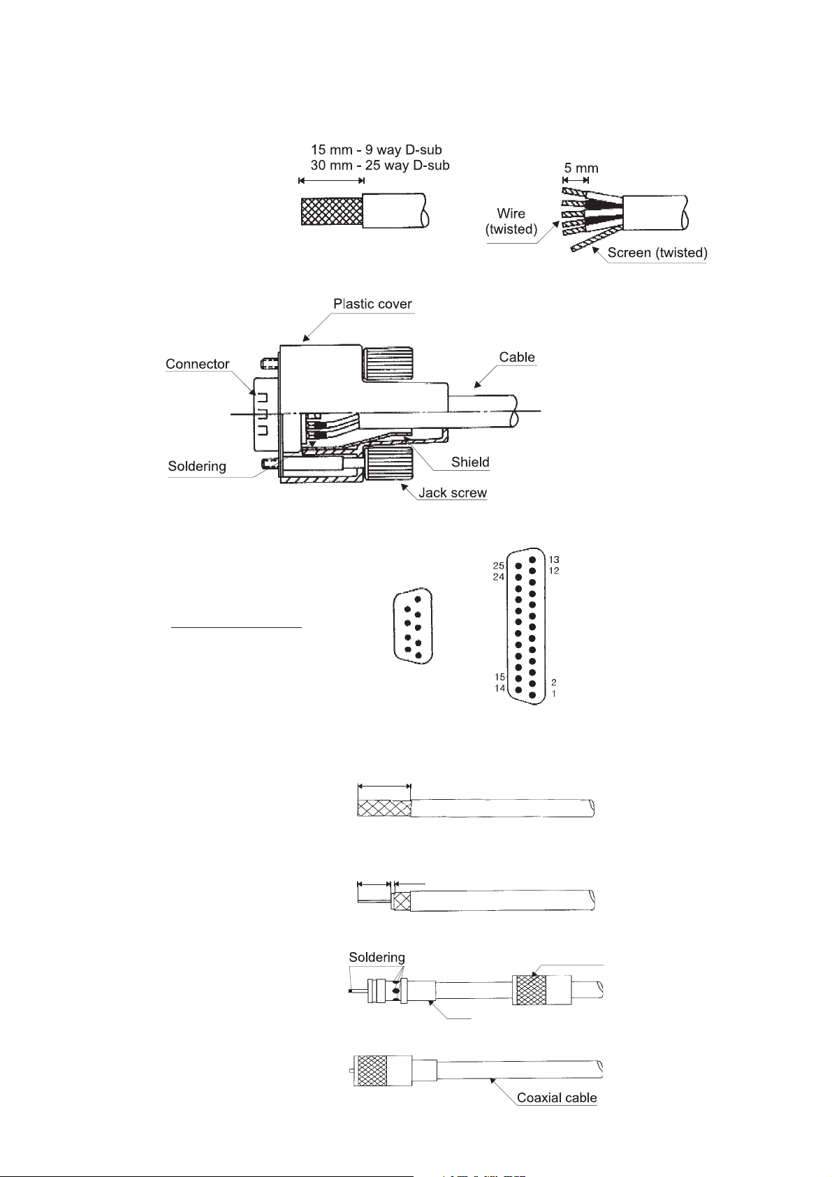
2.8 CONNECTOR MOUNTING INSTRUCTIONS
9 and 25 way D-sub
Slide the plastic cover on the
cable before the wires are
soldered to thepins.
After the pins are soldered; latch
the inner and outer shield into the
connector and snap in. Finally
slide the plastic cover over the
shield and fit the two jack screws
into the cover
.
Contact arrangement
(Viewed from solder side)
PL 259
9
8
7
6
28.5mm
16mm 1.5mm
5
4
3
2
1
Coupling nut
0125
Body
2-13

2 INSTALLATION MF/HF 150W
2.9 POSITION AND TIME INFORMATION
Connection of Navigation Equipment
Navigation equipment complying with the NMEA 0183/IEC 1162 standard may be connected for
automatic position and time updating. Connection is made to the ‘NMEA’ terminals of the Control Unit.
The NMEA receive circuit consists of an optoisolator with a 470 ohms series resistor to insure current
mode operation and a shunt diode to limit reverse bias as shown below. The circuit is isolated from ground.
NMEA IN +
A
The circuit operates with a minimum differential input voltage of
2 volts and takes less than 2 mA
NMEA IN -
B
from the line at that voltage. The
maximum voltage is 15 volts.
37871
Interconnection between devices may be by means of two-conductor shielded twisted-pair wire. Multiple
listeners may be connected to a single talker. The receivers are connected in parallel. The shield should
be connected to the navigator chassis and should not be connected at any listener. However the shield
should be continuous (unbroken) between all listeners.
Following sentences are recognized by the equipment for extraction of position and associated time
information: RMC, GLL, GGA. GLL sentences with and without time information is recognized, time
information is extracted if present.
ZDA, RMC, GLL and GGA sentences are recognized by the equipment for extraction of UTC time
information for automatic setting of the internal real time clock.
2.10 OPTIONS MENU - SETTING UP THE SYSTEM
To open the Options menu, press FUNC and select ‘OPTIONS’ in the ‘SETTINGS’ menu and enter the
access code,1,2,3,4.
0HQX 6XEPH QX
/HYH O
OPTIONS TX BANDS Edit TX frequency band
CONFIGURATION
DSC Select language
6XEPH QX/HYHO
EDIT
Select band
LSB MODE,
REMOTE MOD E,
BATTERY ALARM,
ATU INSTALLE D
LANGUAGE
RX TEST
TX TEST SEND DOTS Send dot Pattern
6XEPH QX/HYHO3D UDPH WHUV
Enable/disable
Enable/disable serial output of decoded
DSC cal ls for test purpos es
SEND Y Send Y frequency (1615 Hz)
SEND B Send B frequency (1785 Hz)
Notes:
TX Bands: Up to 16 frequency bands can be defined. Transmission is inhibited on frequencies
outside the defined bands.
Factory pre-programmed: 1605.0 - 4000.0 kHz
4000.0 - 4438.0 kHz
6200.0 - 6525.0 kHz
8100.0 - 8815.0 kHz
12230.0 - 13200.0 kHz
16360.0 - 17410.0 kHz
18780.0 - 18900.0 kHz
19680.0 - 19800.0 kHz
22000.0 - 22855.0 kHz
25070.0 - 25210.0 kHz
2-14
26100.0 - 26175.0 kHz
0125

2 INSTALLATION MF/HF 150W
Configuration:
LSB mode: When enabled selection of LSB (Lower Side Band) is possible with the MODE key on
the front panel.
Note:
LSB mode is normally not allowed for marine equipment.
Factory default setting: Disabled.
Remote mode: When enabled selection of SSB REMOTE is possible with the MODE key on the front
panel, allowing remote control via the SYS connector of frequency, mode and power
level.
Factory default setting: Disabled.
Battery Alarm: When enabled the voltage at the VBAT input of the SUPPLY ALARM connector is
monitored and an alarm is given by the Control Unit if the voltage is outside the set
range.
Factory default setting: Disabled.
ATU installed: When enabled supply voltage and control signals for the ATU is present at the TX/RX
connector. When disabled a 50 ohms antenna or dummy load may be connected to
TX/RX.
Factory default setting: Enabled.
DSC:
Language: Factory default setting: English.
RX test: When enabled decoded call sequences are routed to the RS-232 port of the SYS
connector. Baud rate: 2400 baud. Parity/data bits: Odd/8.
Factory default setting: Disabled.
TX test: For generation of continuous B or Y signal and dot pattern. DSC mode must be
selected.
2.11 DSC PROGRAMMING
Programming of DSC self-identification
The Maritime Mobile Service Identity (MMSI) assigned to the station must be stored in the DSC
modem before it can be used on board the ship. The MMSI number will be requested each time the
equipment is switched on until it has been stored.
Key in the MMSI number of the ship. Check the number carefully and select ‘ENTER’. After the MMSI
number has been entered it is necessary the restart the system to effect the change: Switch supply off
and on. Check the MMSI number by selecting FUNC, ‘INFO & TEST’, ‘INFORMATION’, ‘MMSI’ and read
the number.
Once the MMSI number has been stored in the DSC modem, change of self-identification is not possible
(only after a factory resetting).
Programming of DSC group-identification
Six different group identities may be assigned to the station. Group call identity numbers always contain
a leading zero. The group call identities must be stored in the DSC modem before it is able to
respond to group calls.
Select FUNC FUNC, ‘INFO & TEST’, ‘INFORMATION’, ‘MMSI’, ‘EDIT GROUP’. Key in the group call
identities and select ‘OK’.
0125
2-15

2 INSTALLATION MF/HF 150W
2.12 BATTERY ALARM ADJUSTMENT
Connect a voltmeter and an external power supply capable of delivering 1.0 A and adjustable up to 33
V DC to the VBAT- and VBAT+ input of the SUPPLY ALARM connector on the Transceiver Unit. Open
the Transceiver Unit to gain access to the potentiometers on Control/Interconnection Module 636510.
Low voltage alarm
1. Adjust the external power supply to the desired low voltage alarm level (22 – 24 V).
2. Watch the Alarm LED.
3. Now carefully turn the potentiometer marked ‘Batt. low adj.’ until the light in the Alarm LED just
disappears.
Factory setting: 23.5 V
High voltage alarm
1. Adjust the external power supply to the desired high voltage alarm level (27 – 32 V).
2. Watch the Alarm LED.
3. Now carefully turn the potentiometer marked ‘Batt. high adj.’ until the light in the Alarm LED just
disappears.
Factory setting: 29.5 V
2.13 FACTORY RESETTING
1. Switch supply off.
2. Insert factory resetting plug (see below) in Control Unit ALARM connector.
3. Switch supply on.
4. The Control Unit indicates ‘Factory Reset’ and requests MMSI number.
5. Remove factory resetting plug.
All programmable parameters are now reset to the factory default values.
Factory resetting plug: Pin 9 + 13 and pin 8 + 11 shorted. If pin 8 +11 is shorted only MMSI is reset.
2.14 FINAL INSTALLATION CHECK
For operation of the equipment please refer to the Operator’s Manual.
Check the hardware configuration of the transceiver by selecting FUNC and the ‘INFO & TEST’,
‘INFORMATION’ ‘HW VERSION’ menu items, in particular check that the Antenna Tuning Unit is
recognized, if installed.
Perform a Self Test of the transceiver by selecting FUNC and the ‘INFO & TEST’, ‘CHECK’, ‘SELFTEST’
menu items. The self test is performed automatically and is used for verification of all functions. Check
the transmitter in all marine bands.
The Antenna Tuning Unit will tune automatically to the antenna first time the equipment is keyed on a
new frequency or when the TUNE button is pressed. During the tune sequence and normal transmission
all transmitter circuits are monitored to ensure safe operating conditions. If transmission conditions are
bad ( bad antenna installation, high temperatures, etc. ) the transmitted power will be reduced to a safe
limit. If the transmission condition is improved automatic recovery to full power takes place.
The protection can be investigated by selecting FUNC and the ‘INFO & TEST’, ‘CHECK’, ‘TX PROTECTION’ menu items. The displayed protection code(s) is described in the Service chapter of this manual.
If a GPS is connected, check position and time in the DSC Status display.
If time is not contained in the NMEA sentences the time of position is indicated as —:—. In this case check
if the GPS output setting can be changed to allow time information. Otherwise UTC time must be entered
manually each time the transceiver is switched on.
Send a DSC test call to the appropriate coast station. The acknowledgement from the coast station is
received by the 2187.5 kHz watch receiver if the call was sent on that frequency. If the call is sent on HF
only the audio signal output from the 2187.5 kHz watch receiver should be checked by selecting FUNC
and the ‘INFO & TEST’, ‘MONITOR’, ‘WR AUDIO’ menu items.
2-16
0125

CONTENTS
3 TECHNICAL DESCRIPTION 3-1
3.1 CONTROL UNIT 3-1
3.2 TRANSCEIVER UNIT 3-1
3.3 CONTROL / INTERCON MODULE 636510 3-1
3.4 SYNTH. AND DSC WR MODULE 636511 3-1
3.5 RX/EX SIGNAL PATH MODULE 636515 3-2
3.6 PA AND FILTERS MODULE 636520 3-2
3.7 SMPS MODULE 636530 3-2
3.8 TRANSCEIVER UNIT BLOCK DIAGRAM 3-3
3.9 TRANSCEIVER UNIT INTERCONNECTION DIAGRAM 3-4
3.10 ANTENNA TUNING UNIT 3-5
3.11 ANTENNA TUNING UNIT BLOCK DIAGRAM 3-5
3.12 POWER CONTROL AND PROTECTION SYSTEM 3-6
3.13 POWER CONTROL AND PROTECTION SYSTEM 3-7
0125


MF/HF 150W
3 TECHNICAL DESCRIPTION
3.1 CONTROL UNIT
The control unit consists of a main module, a display module and a keyboard module.
The main module consists of the digital part, i.e. the microprocessor, program FLASH PROM,
configuration FLASH PROM, RAM, ScanBus data communication driver, SPARC-Bus driver. The main
module also consists of an analog part, i.e. the voltage regulators, the analog interface circuits and the
analog output drivers (audio and light). The main module contains the encoder and the potentiometer.
The display module contains the graphic display (256x64) dots, and backlight for the display.
3.2 TRANSCEIVER UNIT
Block diagram page 3-3, Interconnection diagram page 3-4.
The Transceiver Unit consists of five modules. Three modules located in the base part of the unit: a control
and interconnection module, a receiver/exciter signal path module, and a synthesizer and DSC RX
module including master oscillator, and two modules are located in the door part of the unit: a power
amplifier module including filter bank and a switched mode power supply. The main wiring is by ribbon
cables with Micro MaTch connectors. RF signals are routed in coaxial cables using Taico, MCX and BNC
connectors.
3.3 CONTROL / INTERCON MODULE 636510
The Control/Intercon module performs the digital and analogue control of the transceiver functions
requested by the control unit and contains interconnection circuits. The central part is the CPU. The
program software is contained in Flash PROM. A separate Flash PROM holds the configuration
parameters. The processor communicates with the CU via the CAN interface, with auxiliary equipment
via an RS-232 interface and via the ATU via a modem circuit. Internal communication is via the TU Bus.
The transmitter is monitored via the PA Peak, Filter Peak and Filter Average detectors. An adjustable
opto-isolated battery detector circuit monitors the battery voltage at the Supply Alarm connector and
triggers an alarm when outside the set range. The CPU also performs DSC modulator and dual DSC
demodulator functions. The modulator output is through a transversal filter. Audio switching allows loop
back test. Audio circuits convert between unbalanced and balanced lines used by the ScanBus.
3.4 SYNTH. AND DSC WR MODULE 636511
The Synthesiser part includes Master oscillator, dividers, 3.LO PLL and VCO, 2.LO filters and multiplier
and 1.LO fractional N system as well as both 1. and 2. DSC LO PLL and VCO. The Master oscillator
generates a 17.8176MHz reference signal which is distributed to the local LO sub-circuits. The local LO
circuits then generate the appropriate frequencies used in the MF/HF transceiver and the DSC receiver.
The DSC Watch receiver includes antenna supply, Protection, front-end filters, 1.Mixer, IF amplifiers and
filter, 2. Mixer, DSC filter Hard limiter and an AGC/Check circuit. The antenna supply powers an active
antenna, which sends the signal through the protection circuit to the front-end filter. From the filter the
signal is down converted to IF (455kHz) and passed through the first amplifier in the receiver. After some
amplification the signal is sent through a SSB filter removing the frequency components far from the
wanted signal, and then it is sent through the AGC amplifier. Next step is the down conversion to BB,
where the major filtration is done. The filtered signal is passed through a hard limiter with an AGC output
to the digital demodulator on the Control/Intercon module. The AGC output is fed to an AGC detector,
which drives both the Check detector and the AGC amplifier (with some linearization)
0125
3-1

3 TECHNICAL DESCRIPTION MF/HF 150W
3.5 RX/EX SIGNAL PATH MODULE 636515
The RX signal path includes protection, pre-selection, mixers, IF amplifiers, filter bank, demodulator,
squelch and audio. The RX signal path has Automatic Gain Control. The RX signal path performs the
handling of the received antenna signal and delivers an AF signal, via the Control/Intercon module where
the AF signal is converted from an unbalanced to a balanced signal, to the Control Unit.
The RX signal path also includes a DSC receiver signal path, which uses the MF/HF signal path, until the
last down conversion. DSC part includes a mixer, base band filter, hard limiter and separate AGC
detector. During DSC reception, the DSC part overrules the normal MF/HF reception.
The EX signal path includes AF compressor, modulator, filter bank, mixers and EX output amplifiers. The
EX signal path has Automatic Loop Control. The EX signal path generates the modulated RF signal,
adjusted to correct level - ALC adjusted signal, to the Power Amplifier.
The RX / EX signal path is controlled by the Control/Intercon module and receives its injection signal from
the Synth./DSC WR module.
3.6 PA AND FILTERS MODULE 636520
The PA and Filters module includes PA drivers, PA-stage, protection circuits, bias circuits key circuit and
five low-pass filters with relays and relay drivers. The PA and Filters receives the modulated RF input
signal from the RX/EX Signal Path and delivers the amplified and filtered output signal to the TX/RX
connector via a receive/transmit relay on the Control/Intercon module.
The low-pass filters removes the unwanted harmonic frequencies from the PA signal. The Filpeak and
PAprotec outputs are monitoring signals for the Control/Intercon module. The driver and final power
amplifier stages are galvanic isolated on input and output as they are supplied directly from the 24 V DC
input. The selection of low-pass filter is controlled by the Control/Intercon module.
The PA filters cover the frequency ranges:
1.6 – 3.1 MHz
3.1 – 5.0 MHz
5.0 – 9.0 MHz
9.0 – 17.0 MHz
17.0 – 29.7 MHz
3.7 SMPS MODULE 636530
The Switched Mode Power Supply supplies the low power circuits of the equipment with the various
stabilized voltages required, and provides galvanic isolation from the supply source. The equipment is
supplied from a 21.6 – 31.2 V DC power source. The module also carries the input filter and PA supply
output which is not galvanic isolated.
The power supply converts the incoming voltage to 7.5 V, +15 V, -15, and 25 V. The SMPS is switched
on from the control unit via the Scanbus SUPPLY ON wire and switched off under software control via
the SUPPLY ON/OFF connection from the Control/Intercon module. The DC supply voltage is sensed by
a BAT INFO detector circuit and fed to the Control/Intercon module for automatic RF output power
adjustment.
3-2
0125

PA AND FILTERS 636520
DSC WR AF
Filter
1700 Hz
3-3
LP Filters
Master
Oscillator
3. LO
RX AF
Demodulator
DSC RX AF
DSC
1700 Hz
Filter Amp.
Bank
Filter
455 kHz
2. LO
1. LO
45 MHz
Filter
and Gain
DSC
2. LO
DSC
1. LO
Filter
455 kHz
Supply
Frontend
Protection
EX SIGNAL
SYNTH. AND DSC WR 636511
RX/EX SIGNAL PATH 636515
- 15 V
+ 15 V
+ 25 V
+ 7.5 V
Mode
Power
Supply
Switched
24V DC
3 TECHNICAL DESCRIPTION MF/HF 150W
3.8 TRANSCEIVER UNIT BLOCK DIAGRAM
SMPS 636530
RX AF
DSC WR AF
DSC RX AF
Modulator
Compressor
TX AF
AF Switch
TX AF
Converter
AF Switch
Filter
RX AF
Converter
CAN
AF Amp.
AF Amp.
SCANBUS
600 Ohm600 Ohm
RS-232
SYS
Interface
TX Key &
TX Inhibit
CPU
Detector
ALARM
SUPPLY
Pre-
Selector
TX SIGNAL
RX SIGNAL
Switch
TX/RX
Modem
TU-ATU
TX/RX
CONTROL/INTERCON 636510
DSC RX
37851
0125

636520
EX SIGNAL
PA AND FILTERS
GND
RX AF
TX AF
AGC
MGC/ALC
DSC RX AF
DSC WR AF
SUPPLY OFF
SUPPLY ON
BATINFO
+25V
+25V
+25V
-15V
-15V
+15V
+15V
+7.5V
+7.5V
GND
X2
GND
ADR0
ADR1
ADR2
ADR3
DATA0
DATA1
DATA2
DATA3
DATA4
DATA5
DATA6
DATA7
STROBE
GND
PA KEY
PA TEMP
PA PROTEC
FILPEAK
GND
X11
0125
X1
1
2
3
4
5
6
7
8
9
10
11
12
13
14
15
16
17
18
19
20
1
2
3
4
5
6
7
8
9
10
11
12
13
14
15
16
17
18
19
20
X1
TX AF
DSC WR AF
DSC RX AF
MGC/ALC
BATINFO
AGC
RX AF
SUPPLY OFF
2
2
RX AF
3
3
TX AF
AGC
MGC/ALC
7
854
6
7
854
6
DSC RX AF
DSC WR AF
SUPPLY OFF
SUPPLY ON
10
9
10
9
BATINFO
SUPPLY ON
GND
1
1
X1
GND
636511
SYNTH. AND DSC WR
X2
DATA0
ADR3
ADR0
ADR2
-15V
+25V
+25V
-15V
+25V
11
15
161817
131214
151618
131214
-15V
-15V
+25V11+15V
+25V
+25V
+15V
17
+15V
+15V
+7.5V
19
19
+7.5V
+7.5V
+7.5V
GND
20
W1
20
GND
DATA1
GND
ADR1
1
735
4
2
6
365
498
7
1
2
X2
GND
ADR1
ADR3
ADR0
ADR2
DATA0
DATA1
8
DATA2
DATA3
9
DATA2
DATA3
DATA4
10
10
DATA4
DATA5
DATA5
GND
DATA7
DATA6
STROBE
141517
121113
1211151417
13
GND
DATA7
DATA6
STROBE
PA KEY
16
16
PA KEY
PA PROTEC
PA TEMP
FILPEAK
18
19
20
182019
FILPEAK
PA TEMP
PA PROTEC
GND
GND
W2
2. LO
1. LO
X12
X13
W13
W12
X12
X13
X11
1. LO
2. LO
EX SIGNAL
3. LO
X14
W14
X14
3. LO
DSC RX
X10
X3
124
143
X3
GND
GND
636515
GND
+15V
+25V
+15V
+7.5V
-15V
141316
159111012
171918
+7.5V
GND
20
BATINFO
SUPPLY OFF
GND
GND
SUPPLY ON
GND
GND
GND
5
8
7
3
6
PA+
PA+
1
2
-15V
+25V
+25V
W3
5
8
7
2
9
6
GND
GND
GND
GND
GND
GND
SUPPLY ON
SUPPLY OFF
111012
+25V20+15V
+25V
BATINFO
+25V
141316
15
-15V
-15V
171918
+15V
+7.5V
+7.5V
GND
1
2
X4
PA+
PA+
PA+
X5
PA -
PA -
PA -
PA -
PA -
PA+
PA -
PA+
PA+X4PA+
19
18
20
18
1
2
W4
1218
19
18
20
X5
PA -
PA -
PA -
PA -
PA -
PA+
PA -
PA+
PA+
TX SIGNAL
X8
PA+
PA -
19
20
X8
RX/EX SIGNAL PATH
W1
W2
RX SIGNAL
X9
W5
W10
W9
3
1
19
20
PA -
PA+
2
X1
GND
TX AF
RX AF
548
AGC
MGC/ALC
7610
9
DSC RX AF
DSC WR AF
SUPPLY ON
SUPPLY OFF
11
BATINFO
+25V
+25V
19
+7.5V
+7.5V
1
2
20
X2
GND
GND
ADR0
13121615181714
-15V
-15V
+15V
+15V
+25V
365
498
ADR1
ADR2
ADR3
7
DATA0
DATA1
DATA2
DATA3
10
DATA4
1215141716
11
DATA5
DATA6
13
DATA7
GND
PA KEY
STROBE
182019
FILPEAK
PA TEMP
PA PROTEC
GND
X9
TX SIGNAL
RX SIGNAL
636530
636510
SMPS
CONTROL/INTERCON
+
-
24V DC
DATA-
AF+
DATA+
SUPPLY ON
143
2
SCANBUS
TX KEYED
SYS
DATA OUT
EXT KEY
1
2
DATA IN
TX INHIBIT
365
4
LINE OUT
GND
LINE IN7+12V
8
9
1
2
ALARM
SUPPLY
AC ALR
GND
VBAT-
76543
VBAT+
8
TX/RX
9
TX/RX
RX AF+
+25V
AF-
RX AF-
GND
8
7
5
9
6
DSC RX
DSC RX
37848
3 TECHNICAL DESCRIPTION MF/HF 150W
3.9 TRANSCEIVER UNIT INTERCONNECTION DIAGRAM
3-4

3 TECHNICAL DESCRIPTION MF/HF 150W
3.10 ANTENNA TUNING UNIT
ATU MODULE 636540
The ATU module comprises tuning network, measuring system and micro-controller circuits. The ATU
module matches the impedance of the antenna to 50 ohm in order to gain the best possible SWR. The
ATU module communicates tuning process and frequency information with the transceiver unit. The
tuning network consists of Capacitor Bank 1, Capacitor Bank 2, and an Inductor Bank. With these it is
possible to form either an L-network or a p-network. The capacitor banks and inductor bank are built up
by binary related capacitors respectively binary related coils. The setting of capacitance and inductance
is accomplished by relays. A current detector at the antenna output terminal is used for measuring the
antenna current for display at the control unit. To prevent overload of the relays, current detectors are
incorporated in the Inductor Bank and in Capacitor Bank 2 and information fed back to the transceiver
unit to decrease the output power if maximum permissible current is exceeded. To prevent overheating
a temperature sensor is incorporated which at excessive temperatures commands the transceiver to
reduce the output power.
In receive mode an RX-Amplifier included in the Antenna Tuning Unit will be inserted, to improve the
sensitivity of the system. It is possible to select the sensitivity in three steps (OFF, NORMAL, MAX) from
the control unit.
3.11 ANTENNA TUNING UNIT BLOCK DIAGRAM
RX/TX/
ATU/COM
24V DC
24V
RF filter
High Pass Filter
Modem filter
Demodulator
DC regulators
Tune Att.
control by
Modulator
to relays
4 dB
uP
12V
regulator
13/24V
SMPS
control by
uP
Tuning circuit
Directional
Coupler
26dB
Vw
Vref
5V
regulator
to digital
circuits
24V in Rx & Tune Tx
13V in Tx
to relays
rx
tx
control
control
Rx/Tx
IL detector
CB1
banks
RX amplifier
attenuator
control Rx att
L-bank
current
detectors
Rx
on
off
(from uP)
L-bank
Ic
detector
CB2
Rx
Amp
Iant. detector
Antenna
Antenna
Connector
Horn
0125
37858
Phase &
Voltage
Detectors
Micro Prosessor
Temperature
sensor
3-5

3 TECHNICAL DESCRIPTION MF/HF 150W
3.12 POWER CONTROL AND PROTECTION SYSTEM
The Transceiver has an automatic power level system, which ensures that optimum power is delivered
to the Antenna. The Tune Sequence, which is automatically initiated when keying the transmitter after
a frequency change, makes the Tuning Network of the Antenna Tuning Unit tune to the best obtainable
SWR. This is followed by an Automatic Level Control (ALC) adjustment according to the available power
supply voltage, measuring the output current of the PA Filters (FILPEAK @ 10 Vp at full output),
transmitting AM carrier, and setting the overall gain by the ALC voltage (MGC/ALC). It is now possible
to transmit on full output power unless protection is activated or LOW POWER is selected. The output
power is continuously monitored by the microprocessor, and is automatically adjusted during transmission to provide reliable communication .
Power Amplifier Protection
The protection of the power amplifier consists of V+I protection and thermal protection. When PA PEAK,
the output signal of the voltage detector at the output of the power amplifier is exceeding 10 V the output
power is reduced to a safe level. If the ALC loop is at fault, disconnected or responding too slow and the
PA PEAK is exceeding 10V, the gain will be reduced in the power amplifier, operating as a local and
independent PA protection. The thermal protection consist of a temperature sensor on the power amplifier
and an average detector on the Control/Intercon module reducing the output power when the duty cycle
of the transmitted signal exceeds 50% for more than 60 seconds. The available power supply voltage is
measured in the DC power supply and the information BAT INFO is transferred to the Control/Intercon
module. If the supply voltage is dropping the microprocessor will adjust the output power to keep distortion
below the limits.
Antenna Tuning Unit Protection
The ATU is protected by several detectors all monitored by the ATU´s microprocessor, which calculates
the SWR, temperature, maximum voltage and current. If these parameters are not below safe operating
limits it requests for lower power.
Protection Codes
The current status of the power control and protection may be displayed in the form of Protection Codes
by selecting FUNC and the ‘INFO & TEST’, ‘CHECK’ and ‘TX PROTECTION’ menu items. The Protection
Codes are described in the Service chapter of this manual.
It should be noted that protection may be in force even under normal conditions e.g. code nos. 25, 44 and
48:
No. 25 requests lower Pout relatively to increasing SWR at the Power amplifier.
@ SWR= 1.1 reduction will only be a few watt’s
@ SWR= 2.0 reduction will be 2-3 dB
No. 44 and 48 requests lower Pout relatively to increasing V or I at ATU.
This is normal when transmitting on lower frequencies and short antennas (L<< 1/4 wavelength), and /
or parallel capacitance present at the antenna, feeder, insulators, etc.
3-6
0125

3 TECHNICAL DESCRIPTION MF/HF 150W
3.13 POWER CONTROL AND PROTECTION SYSTEM
Det.
Current
Det.
Current
Det.
SWR
24V DC
ATU MODULE 636540
Coax
TU-ATU
24V DC
CONTROL/INTERCON 636510
TX SIGNAL
RX SIGNAL
Det.
Current
Peak Det.
Com
TU-ATU
Demodulator
Com
TU-ATU
Modulator
Sens.
Temp.
CPU
Com
ATU-TU
Com
ATU-TU
FILPEAK
Modulator
Demodulator
Average Det.
Peak Det.
0125
Det.
LP Filters
Protect.
Det.
PA peak
V+I Det.
Sens.
PA AND FILTERS 636520
EX SIGNAL
Temp.
RX/EX SIGNAL PATH 636515
PA PROTEC
PA TEMP
MGC/ALC
Comparator
CPU
D/A
Converter
SMPS 636530
A/D
Converter
BATINFO
Det.
Power
Supply
37853
3-7


MF/HF 150W
CONTENTS
4 SERVICE 4-1
4.1 PREVENTIVE MAINTENANCE 4-1
4.2 REALIGNMENT OF MASTER OSCILLATOR 4-1
4.3 SOFTWARE UPDATE 4-2
4.3.1 SETUP 4-2
4.3.2 PC 4-2
4.3.3 CABLE 4-2
4.3.4 PROCEDURE 4-2
4.4 TROUBLE SHOOTING 4-2
4.5 POWER PROTECTION 4-3
4.6 SELF TEST 4-5
0125


MF/HF 150W
4 SERVICE
4.1 PREVENTIVE MAINTENANCE
Due to the modern design of the transceiver preventive maintenance can be reduced to a minimum
provided the equipment is correctly installed. To ensure maximum performance and minimum repair
trouble we recommend you to follow the below stated headlines for preventive maintenance.
1. The condition of the battery should be checked at frequent intervals. The battery must always be
fully charged and should be topped up frequently with distilled water (liquid should be 5 to 10 mm
above the plates).
2. Check the condition of antenna installation, ground connection and cables at regular intervals.
3. Keep antenna feed-through insulators clean and dry.
4. Ensure that no objects are obstructing the free airflow through the cooling fins of the Transceiver
Unit and keep the units free of dust accumulation to prevent overheating.
5. For cleaning use a damp cloth. Sticky dirt may be removed using a cloth with a weak soap solution.
Wipe off with a clean cloth.
4.2 REALIGNMENT OF MASTER OSCILLATOR
The Master Oscillator determines the exact transmit and receive frequencies of the equipment. All
oscillators age very slowly with time, typically with the highest drift rate the first year, approaching zero
drift after some years. Adjustment should be performed by a qualified technician with the necessary test
equipment at his disposal.
1. Measuring Equipment:
Frequency Counter: Frequency range 100 MHz
Input impedance = 1 Mohm
Sensitivity at least 0.2 Vrms
Accuracy better than 0.01ppm
2. Preparations:
2.1 Switch on the power at least 30 minutes before adjustment.
2.2 Open the front of the Transceiver Unit.
2.3 Locate X13 on SYNTH.AND DSC WR module 636511 carrying the 2. Local Oscillator signal
from the synthesizer to the RX/EX Signal Path. Connect the frequency counter probe to the
inner conductor of the X13 socket on the synthesizer.
2.4 The ambient temperature should be within 10 to 30 deg. Celsius. Do not adjust the Master
Oscillator shortly after long keying sequences of the transmitter. Be sure that thermal
equilibrium has taken place before adjustment.
3. Realignment of Master Oscillator:
3.1 Locate the Master Oscillator adjustment hole in the metal cover over SYNTH.AND DSC WR
module 636511. Use a small screwdriver to gently adjust the frequency.
3.2 Adjust the frequency as close as possible to 44.544 000 MHz.
Adjustment tolerance +/-1Hz.
3.3 Remove the counter probe and refit the front of the Transceiver Unit.
0125
4-1

4 SERVICE MF/HF 150W
4.3 SOFTWARE UPDATE
Code and configuration software are placed in flash memory. Consequently it is not necessary to
dismantle the units in order to update the software; a PC link must be used.
4.3.1 Setup
In order to perform a software update, a PC with a communication program (e.g. Procomm Plus or
HyperTerminal) and a communication cable are required.
If the Hyper Terminal program is used it is recommended to close and re-start the program if more than
one file has to be downloaded. This should be done between each file download.
4.3.2 PC
In the specific communication program, the Com port must be set to
Item Value
Baudrate 38400
Parity None
Data bits 8
Stop bits 1
Flow control must be set to: None
The communication protocol must be set to: X-Modem.
4.3.3 Cable
The cable must be a 3-wire cable. Supplying more than 3-wire may damage the PC. The PC side of the
cable must be a 9-pin (or 25-pin) female D-sub connector; the CU/TU side must be a 9-pin male D-sub
connector. The cable will be supplied in your accessory kit.
Designation PC CU TU Designation
‘Com port’ ‘Aux ’ ‘Sys’
9-pin 25-pin 9-pin 9-pin
Received Data 2 3 CABLE 2 2 Data Out
Transmitted Data 3 2 3 3 Data In
Ground 5 7 5 5 Ground
4.3.4 Procedure
The PC with the communication program and cabling must be ready before the CU/TU is switched on.
The procedure is as follows.
- Download software from the web site or receive it from your distributor if necessary.
- Switch off PC and CU/TU
- Connect cable to unit to be updated
- Switch on PC
- Enter the communcation program. Setup the Com port and select X-Modem protocol. Select the
upload file (the new software version) and begin uploading.
- Switch on the CU/TU.
Upload will now begin. The result of the upload will be written on the PC when the upload is finished. If
the upload was successful the CU/TU reboots automatically.
4.4 TROUBLE SHOOTING
If a malfunction should occur in the transceiver, the following instructions should be followed in order to
locate the module which is causing the malfunction:
1. Check the hardware configuration of the transceiver by selecting FUNC and the ‘INFO & TEST’,
‘INFORMATION’ and ‘HW VERSION’ menu items, in particular check that the antenna tuning unit
is recognized, if installed.
2. If the malfunction is related to transmission check the current status of the power and protection
monitor. A description of the ’Protection codes’ is included on the following pages.
4-2
0125

4 SERVICE MF/HF 150W
3. If possible execute the built in self test. An ’Error code’ for the failing module will be displayed. A
description of the ’Error codes’ is included in the Self Test section of this chapter.
4. If an execution of the self test failed, check that all cables and plugs are correctly connected, and
that the supply voltage is correct. At this point the fuses should be checked.
5. The next step is to open the Transceiver Unit and :
a. Check the internal fuse, cables and plugs.
b. Check that the +5 V LED (Light Emitting Diode) V1 on the PA AND FILTERS module 636520
is constantly on; indicating that the Switch Mode Power Supply is on and able to produce
+7.5 V DC.
6. If the above steps did not help, please contact your local service agent.
A list of service agents is found on the Internet.
4.5 POWER PROTECTION
The Power and Protection system is monitoring the transmitter circuits during transmission and will
automatically maximize the radiated power to safe limits. The current status of the Power and Protection
monitor is presented in form of protection codes and may be requested at any time by selecting FUNC
and the ‘INFO &TEST’, ‘CHECK’, ‘TX PROTECTION’ menu items.
The display will show the Protection Code. More than one Protection Code may be set. Protection is
automatically reset when the transmit conditions are normalized.
Protection Code Groups:
No. Group
00 No protection set
10 - 17 TU power regulation problems. Perform a Self Test.
20 - 23 TU hardware protection.
40 - 51 ATU protection.
Protection Code explanation:
0 No protection
10 - 17 in general: Failure in power regulation loop
Perform an Automatic Self Test.
10 Tune Power Low
Measurement:
CONTROL/INTERCON module 636510 measures too low power output.
Tune power < 10W.
Protection made: ATU selects feed through setting after „TU Failure“ command.
Power regulation inhibited
Possible cause: TU - ATU coaxial cable open.
11 Tune Power High
Measurement:
CONTROL/INTERCON module 636510 measures too high power output.
Tune power > 30W.
Protection made: ATU selects feed through setting after „TU Failure“ command.
12 ALC Power High
Measurement:
CONTROL/INTERCON module 636510 measures too high power output.
ALC power was too high.
Protection made: Exciter level set to approx. +8dBm.
0125
4-3

4 SERVICE MF/HF 150W
13 Supply failure
Measurement: Supply voltage high.
Protection made: TX key inhibited.
14 ALC Power Low
Measurement:
CONTROL/INTERCON module 636510 measures too low power output.
ALC power was too low.
Protection made: Exciter level set to approx. +8dBm.
15 TU-ATU Failure
Measurement:
CONTROL/INTERCON module 636510 measures too high power output.
TX power was too high.
Protection made: Automatic power regulation inhibited.
16 Low Power High
Measurement:
CONTROL/INTERCON module 636510 measures too high power output.
Low Power was too high.
Protection made: Power set as Low as possible.
17 Full Power High
Measurement:
CONTROL/INTERCON module 636510 measures too high power output.
Full Power was too high.
Protection made: Automatic power regulation inhibited.
20 - 23: TU protection by TU hardware
20 PA Temp
Measurement: PA temperature too high.
Protection made: Output power decreased.
Possible cause: Free airflow through the cooling fins of the Transceiver Unit impaired.
21 PA SWR high
Measurement: PA SWR was too high.
Reflected power was detected.
Protection made: Output power decreased.
Possible cause: TU - ATU coaxial cable or antenna.
Note: It is necessary to select low power or to switch off the equipment to reset
the protection
22 High Average
Measurement: Average power reduced to 100W.
Possible cause: CW keyed for more than 1 minute.
23 PA Hot
Measurement: PA temperature continuously high.
Protection made: Key inhibit for 5 min.
Possible cause: Free airflow through the cooling fins of the Transceiver Unit impaired.
24 TX Inhibit
Measurement: External „TX Inhibit“ input is activated.
Action made: TX key inhibit.
25 PA SWR
Measurement: PA SWR was high.
Protection made: Output power reduced to safe limits.
Possible cause: High SWR or change in antenna impedance.
40 - 51: ATU protection
40 Not Tuned
Measurement: ATU failed tuning the antenna.
Protection made: ATU selects feed through setting.
Possible cause: Antenna installation.
4-4
0125

4 SERVICE MF/HF 150W
41 No Tune Power
Measurement: ATU measured no tune power.
Protection made: ATU selects feed through setting.
Possible cause: TU - ATU coaxial cable shorted.
42 Bad SWR
Measurement: ATU measured SWR > 8 during Tune Procedure.
Protection made: ATU selects feed through setting.
Possible cause: Bad antenna impedance on the selected frequency.
43 High SWR
Measurement: ATU measured SWR >3 but <8 during Tune Procedure.
Possible cause: Poor antenna impedance on the selected frequency.
44 V or I
Measurement: ATU measured that the maximum voltage or current rating is reached
during ALC adjustment.
Possible cause: A short antenna and a low frequency.
45 Temp
Measurement: ATU requests for lower power during TX.
Possible cause: Temperature inside ATU cabinet is too high.
46 Bad SWR TX
Measurement: ATU measured SWR > 8 during transmission.
Possible cause: Bad antenna impedance on the selected frequency.
47 High SWR TX
Measurement: ATU measured SWR >3 but <8 during transmission.
Possible cause: Poor antenna impedance on the selected frequency.
48 V or I high TX
Measurement: ATU measured that the maximum voltage or current rating is reached
during transmission.
Possible cause: A short antenna and a low frequency.
50 V or I high
Measurement: ATU measured that the maximum voltage or current rating is reached
during ALC adjustment and the power had to be reduced more than 6 dB.
Possible cause: A bad antenna and a low frequency.
51 TU-ATU com bad
Measurement: TU - ATU communication is not operating.
Protection made: Key inhibit.
Possible cause: TU - ATU communication problem.
4.6 SELF TEST
Introduction
The ’SELF TEST’ BITE (Built-In Test Equipment) of the transceiver is used as a fault diagnosing tool for
the service technician. It may also be used by the operator to obtain additional information on a problem
when ordering service.
The ’SELF TEST’ checks the vital functions of the Transceivers modules by performing and monitoring
a sequence of operations. The program controls the analog and digital set ups necessary to perform each
test step in the line of tests executed during the ’SELF TEST’. These set ups will result in a digital feed
back from go/no-go analog check detectors, A/D converters or digital circuits.
0125
4-5

4 SERVICE MF/HF 150W
Self test description
The ‘SELF TEST’ is started by selecting FUNC and the ‘INFO &TEST’, ‘CHECK’, ‘SELFTEST’ menu
items.
All tests which does not involve transmission will automatically be performed successively until the last
test has passed or an error condition has occurred. The test number and a name is displayed as the test
proceeds.
After the last test the user has the option to continue with a test of the transmitter with power delivered
to the antenna. The user selects the test frequency. Both receiver and transmitter are set to the test
frequency which should be selected so as to cause minimal disturbance of others.
If stopped due to an error condition, an error code is displayed. Only one error code is given as a result
of each test (the lowest number fitting). The user has the option to repeat the test or cancel.
It is also possible to select a single test step for service purposes. Tests may be repeated several times
giving a technician the opportunity to make measurements. Note that test on an arbitrary test number may
provide a false indication to where the problem is, as the self test assumes that all previous test steps have
been performed and found OK.
Explanations to the ’Error codes’ are listed on the following pages.
Test 1 - CU RAM
A write/read test is performed on the Random Access Memory in the Control Unit.
Error code Conditions Possible error sources
0101 CU RAM failure CONTROL UNIT
Test 2 - CU CAN Controller
A test is performed on the CAN connection between CU and TU.
Error code Conditions Possible error sources
0201 No CAN connection ScanBus cable or CONTROL UNIT
or CONTROL/INTERCON 36510
0202 CAN connection lost ScanBus cable or CONTROL UNIT
or CONTROL/INTERCON 36510
Test 3 - TU RAM
A write/read test is performed on the Random Access Memory in the Transceiver Unit.
Error code Conditions Possible error sources
0301 TU RAM failure CONTROL/INTERCON module 636510
Test 4 - SUPPLY VOLTAGES
+15 V and –15 V is checked.
(This test is not implemented initially).
Error code Conditions Possible error sources
0401 +15 V missing SMPS 636530 or cabling
0402 -15 V missing SMPS 636530 or cabling
Test 5 - DSC MODEM
A loop-back test is made on the DSC modulator/demodulators.
Error code Conditions Possible error sources
0501 Demodulator 1 failure CONTROL/INTERCON module 636510
0502 Demodulator 2 failure CONTROL/INTERCON module 636510
0503 Modulator or demodulator 1
and demodulator 2 failure CONTROL/INTERCON module 636510
[Test 6 - reserved]
Test 7 - MASTER OSCILLATOR
The Master oscillator output is checked for signal.
Error code Conditions Possible error sources
0701 MO CHECK = No signal SYNTH. AND DSC WR module 636511
4-6
or SMPS module 636530 or cabling
0125

4 SERVICE MF/HF 150W
Test 8 - 2. LO
2. LO is checked for signal.
Error code Conditions Possible error sources
0801 2. LO CHECK = No signal SYNTH. AND DSC WR module 636511
Test 9 - 1. LO out of lock
Tests if 1. LO gets out of lock by setting it to an out-of-band frequency to check that the microprocessor
can control the synthesizer.
Settings:
Band: 45 – 52.5 MHz
1. LO: 75.00000 MHz
Error code Conditions Possible error sources
0901 1. LO CHECK = Lock SYNTH. AND DSC WR module 636511
Test 10 - 1. LO band 0 low border
1. LO is checked for lock in band 0, low border.
Settings:
Band: 45 – 52.5 MHz
1. LO: 45.00000 MHz
Error code Conditions Possible error sources
1001 1. LO CHECK = No lock SYNTH. AND DSC WR module 636511
Test 11 - 1. LO band 0 high border
1. LO is checked for lock in band 0, high border.
Settings:
Band: 45 – 52.5 MHz
1. LO: 52.50000 MHz
Error code Conditions Possible error sources
1101 1. LO CHECK = No lock SYNTH. AND DSC WR module 636511
Test 12 - 1. LO band 1 low border
1. LO is checked for lock in band 1, low border.
Settings:
Band: 52.5 - 60 MHz
1. LO: 52.50000 MHz
Error code Conditions Possible error sources
1201 1. LO CHECK = No lock SYNTH. AND DSC WR module 636511
Test 13 - 1. LO band 1 high border
1. LO is checked for lock in band 1, high border.
Settings:
Band: 52.5 - 60 MHz
1. LO: 60.00000 MHz
Error code Conditions Possible error sources
1301 1. LO CHECK = No lock SYNTH. AND DSC WR module 636511
Test 14 - 1. LO band 2 low border
1. LO is checked for lock in band 2, low border.
Settings:
Band: 60 – 67.5 MHz
1. LO: 60.00000 MHz
Error code Conditions Possible error sources
1401 1. LO CHECK = No lock SYNTH. AND DSC WR module 636511
0125
4-7

4 SERVICE MF/HF 150W
Test 15 - 1. LO band 2 high border
1. LO is checked for lock in band 2, high border.
Settings:
Band: 60 – 67.5 MHz
1. LO: 67.50000 MHz
Error code Conditions Possible error sources
1501 1. LO CHECK = No lock SYNTH. AND DSC WR module 636511
Test 16 - 1. LO band 3 low border
1. LO is checked for lock in band 3, low border.
Settings:
Band: 67.5 – 75 MHz
1. LO: 67.50000 MHz
Error code Conditions Possible error sources
1601 1. LO CHECK = No lock SYNTH. AND DSC WR module 636511
Test 17 - 1. LO band 3 high border
1. LO is checked for lock in band 3, high border.
Settings:
Band: 67.5 – 75 MHz
1. LO: 75.00000 MHz
Error code Conditions Possible error sources
1701 1. LO CHECK = No lock SYNTH. AND DSC WR module 636511
Test 18 - 3. LO out of lock
Tests if 3. LO gets out of lock by setting it to an out-of-band frequency to check that the microprocessor
can control the synthesizer.
Settings:
3. LO: 400.00 kHz
Error code Conditions Possible error sources
1801 3. LO CHECK = Lock SYNTH. AND DSC WR module 636511
Test 19 - 3. LO low border
3. LO is checked for lock at low border.
Settings:
3. LO: 452.50 kHz
Error code Conditions Possible error sources
1901 3. LO CHECK = No lock SYNTH. AND DSC WR module 636511
Test 20 - 3. LO high border
3. LO is checked for lock at high border.
Settings:
3. LO: 460.50 kHz
Error code Conditions Possible error sources
2001 3. LO CHECK = No lock SYNTH. AND DSC WR module 636511
Test 21 - 1. LO DSC out of lock
Tests if 1. LO of the DSC watch receiver gets out of lock by setting it to an out-of-band frequency to check
that the microprocessor can control the synthesizer.
Error code Conditions Possible error sources
2101 DSC 1. LO CHECK = Lock SYNTH. AND DSC WR module 636511
4-8
0125

4 SERVICE MF/HF 150W
Test 22 - 1. LO DSC
1. LO of the DSC Watch Receiver is checked for lock at the nominal frequency.
Settings:
1. LO DSC: 2.6425 MHz
Error code Conditions Possible error sources
2201 DSC 1. LO CHECK = No lock SYNTH. AND DSC WR module 636511
Test 23 - 2. LO DSC out of lock
Tests if 2. LO of the DSC Watch Receiver gets out of lock by setting it to an out-of-band frequency to check
that the microprocessor can control the synthesizer.
Error code Conditions Possible error sources
2301 DSC 2. LO CHECK = Lock SYNTH. AND DSC WR module 636511
Test 24 - 2. LO DSC
2. LO of the DSC Watch Receiver is checked for lock at the nominal frequency.
Settings:
2. LO DSC: 456.7 kHz
Error code Conditions Possible error sources
2401 DSC 2. LO CHECK = No lock SYNTH. AND DSC WR module 636511
Test 25 - DSC WR
The DSC Watch Receiver signal path is checked by injecting a 2227.2 kHz test signal at the receiver input.
The output is checked for signal by measuring the AGC voltage.
Settings:
1. LO DSC: 2.6822 MHz
2. LO DSC: 456.70 kHz
CHECK GEN ENB = On
Error code Conditions Possible error sources
2501 DSC WR CHECK = No signal SYNTH. AND DSC WR module 636511
Test 26 - DSC WR with no signal
The DSC Watch Receiver signal path is checked with no signal. The 2. LO DSC is offset by 5 kHz to mute
antenna signals. The output is checked for no signal by measuring the AGC voltage.
Settings:
1. LO DSC: 2.6822 MHz
2. LO DSC: 461.70 kHz
CHECK GEN ENB = Off
Error code Conditions Possible error sources
2601 DSC WR CHECK = Signal SYNTH. AND DSC WR module 636511
[Test 27 - reserved]
Test 28 - RX AF path on CONTROL/INTERCON module 636510 with no signal
The AF path on Control and Interconnection 510 is checked with no signal present.
Error code Conditions Possible error sources
2801 RX AF CHECK 510 = Signal CONTROL/INTERCON module 636510
0125
4-9

4 SERVICE MF/HF 150W
Test 29 - RX AF path on CONTROL/INTERCON module 636510 with signal
The AF path on Control and Interconnection 510 with signal present.
A 2227.2 kHz test signal is injected at the DSC WR receiver input and DSC RX AF is routed to the output
and the RX AF is checked for signal.
Settings:
1. LO DSC: 2.6822 MHz
2. LO DSC: 456.70 kHz
Error code Conditions Possible error sources
2901 RX AF CHECK 510 = No signal CONTROL/INTERCON module 636510 or
SYNTH. AND DSC WR module 636511 or cabling
Test 30 - RX AF path on RX/EX SIGNAL PATH module 636515 with no signal.
Tests the RX AF path on RX/EX Signal Path 515 with no signal present.
Error code Conditions Possible error sources
3001 RX AF CHECK 515 = Signal RX/EX SIGNAL PATH module 636515
3002 RX AF CHECK 510 = Signal CONTROL/INTERCON module 636510 or
RX/EX SIGNAL PATH module 636515
Test 31 - RX SSB mode
The receiver of the RX/EX Signal Path 515 is checked in SSB mode. By choosing the proper synthesizer
frequencies the signal passes the 45 MHz filter and is mixed to a 1 kHz tone in the audio part. The
automatic gain control voltage and RX AF is checked.
Settings:
Band: 45 – 52.5 MHz
1. LO: 44.99900 MHz
3. LO: 456.00 kHz
Error code Conditions Possible error sources
3101 RX AF CHECK 515 = No signal RX/EX SIGNAL PATH module 636515
3102 RX AF CHECK 510 = No signal CONTROL/INTERCON module 636510
3103 No AGC voltage RX/EX SIGNAL PATH module 636515 or
CONTROL/INTERCON module 636510 or
cabling
Test 32 - RX AM mode
The receiver of the RX/EX Signal Path 515 is checked in AM mode. By choosing the proper synthesizer
frequency the signal passes the 45 MHz filter and is mixed to generate an unmodulated carrier. The
automatic gain control voltage and RX AF is checked.
Settings:
Band: 45 – 52.5 MHz
1. LO: 44.99900 MHz
Error code Conditions Possible error sources
3201 RX AF CHECK 515 = Signal RX/EX SIGNAL PATH module 636515
3202 No AGC voltage RX/EX SIGNAL PATH module 636515 or
CONTROL/INTERCON module 636510
Test 33 - RX DSC mode
The receiver of the RX/EX Signal Path 515 is checked in DSC mode. By choosing the proper synthesizer
frequencies the signal passes the 45 MHz filter and is mixed to a 1.7 kHz tone in the audio part. RX AF
is checked.
Settings:
Band: 45 – 52.5 MHz
1. LO: 44.99900 MHz
3. LO: 456.70 kHz
Error code Conditions Possible error sources
3301 RX AF CHECK 515 = No signal RX/EX SIGNAL PATH module 636515
3302 RX AF CHECK 510 = No signal CONTROL/INTERCON module 636510
4-10
0125

4 SERVICE MF/HF 150W
Test 34 - SQUELCH
The squelch circuit of the RX/EX Signal Path 515 is checked in SSB mode. By choosing the proper
synthesizer frequencies the signal passes the 45 MHz filter and is mixed to a 500 Hz tone in the audio
part. This makes the squelch open. Then a 2 kHz tone is generated making the squelch close. Squelch
hold time is also checked.
Settings:
Band: 45 – 52.5 MHz
1. LO: 44.99900 MHz
a) 3. LO: 455.50 kHz (500Hz tone)
b) 3. LO: 457.00 kHz (2 kHz tone)
Error code Conditions Possible error sources
3401 RX AF CHECK 515 = No signal RX/EX SIGNAL PATH module 636515
with 500 Hz tone.
3402 RX AF CHECK 515 = Signal RX/EX SIGNAL PATH module 636515
with 2 kHz tone.
3403 Squelch hold time not ok. RX/EX SIGNAL PATH module 636515
Test 35 - RX AGC
The gain control circuit of the RX/EX Signal Path 515 is checked . By choosing the proper synthesizer
frequency the signal passes the 45 MHz filter and is mixed to a 1 kHz tone in the audio part. By setting
the MGC voltage to low sensitivity the RX AF Check should indicate no AF signal. By setting the MGC
voltage to high sensitivity the RX AF Check should indicate AF signal present.
Settings:
Band: 45 – 52.5 MHz
1. LO: 44.99900 MHz
3. LO: 456.00 kHz
Error code Conditions Possible error sources
3501 RX AF CHECK 515 = Signal RX/EX SIGNAL PATH module 636515 or
with MGC voltage at max. CONTROL/INTERCON module 636510
3502 RX AF CHECK 515 = No signal RX/EX SIGNAL PATH module 636515 or
with MGC voltage at min. CONTROL/INTERCON module 636510
Test 36 - RX ACG hang time
The Automatic Gain Control Hang facility of the RX/EX Signal Path 515 is checked. By choosing the
proper synthesizer frequency the signal passes the 45 MHz filter and is mixed to a 1 kHz tone in the audio
part. The hang function is examined in three steps:
1) Check normal AGC with 1 kHz tone
2) Check that AGC hangs with no signal
3) Check that AGC hang time has ended.
Settings:
Band: 45 – 52.5 MHz
1. LO: 44.99900 MHz
3. LO: 456.00 kHz
Band: 67.5 – 75 MHz
1. LO: 80.00000 MHz
3. LO: 456.00 kHz
Error code Conditions Possible error sources
3601 No AGC voltage with signal on RX/EX SIGNAL PATH module 636515 or
CONTROL/INTERCON module 636510
3602 Hang time too short RX/EX SIGNAL PATH module 636515 or
CONTROL/INTERCON module 636510
3603 Hang time too long RX/EX SIGNAL PATH module 636515 or
CONTROL/INTERCON module 636510
0125
4-11

4 SERVICE MF/HF 150W
Test 37 - EX SSB with no signal.
The exciter of the RX/EX Signal Path 515 is checked in SSB mode. PA and Filters 520 is not keyed. The
exciter is set to produce a 15 MHz SSB signal. No AF input signal. No RF should be detected at the exciter
output.
Settings:
Band: 60 – 67.5 MHz
1. LO: 60.00000 MHz
3. LO: 456.50 kHz
Error code Conditions Possible error sources
3701 EX CHECK = Signal RX/EX SIGNAL PATH module 636515
3702 TX AF CHECK = Signal RX/EX SIGNAL PATH module 636515 or
CONTROL/INTERCON module 636510
Test 38 - EX SSB with signal.
The exciter of the RX/EX Signal Path 515 is checked in SSB mode. PA and Filters 520 is not keyed. The
exciter is set to produce a 15 MHz SSB signal. Input tone from DSC modulator on Control and Interface
Module 510. RF should be detected at the exciter output.
Settings:
Band: 60 – 67.5 MHz
1. LO: 60.00000 MHz
3. LO: 456.50 kHz
Error code Conditions Possible error sources
3801 EX CHECK = No signal and RX/EX SIGNAL PATH module 636515
TX AF CHECK = Signal
3802 EX CHECK = No signal and RX/EX SIGNAL PATH module 636515 or
TX AF CHECK = No signal CONTROL/INTERCON module 636510 or W1
[Test 39 - reserved]
[Test 40 - reserved]
Test 41 - EX TUNE CW
The exciter of the RX/EX Signal Path 515 is checked in Tune CW mode. PA and Filters 520 is not keyed.
The exciter is set to produce a 15 MHz carrier. No AF input signal. RF should be detected at the exciter
output.
Settings:
Band: 60 – 67.5 MHz
1. LO: 60.00000 MHz
3. LO: 456.50 kHz
Error code Conditions Possible error sources
4101 EX CHECK = No signal RX/EX SIGNAL PATH module 636515
Test 42 - EX ALC
The Automatic Level Control on the RX/EX Signal Path 515 is checked. PA and Filters 520 is not keyed.
The exciter is set to produce a 15 MHz CW carrier. No AF input signal. Low and high ALC level. No RF
should be detected at the exciter output with low ALC level. RF should be detected with high ALC level.
Settings:
Band: 60 – 67.5 MHz
1. LO: 60.00000 MHz
3. LO: 456.50 kHz
Error code Conditions Possible error sources
4201 EX CHECK = Signal RX/EX SIGNAL PATH module 636515 or
with ALC low CONTROL/INTERCON module 636510
4202 EX CHECK = No signal RX/EX SIGNAL PATH module 636515 or
with ALC high CONTROL/INTERCON module 636510
4-12
0125

4 SERVICE MF/HF 150W
Test 43 - ATU without RF power
The ATU Module 540 is checked without transmitting. The Transceiver Unit checks that an ATU is
connected and is able to communicate with the TU. The ATU tests RAM, Vforward-, Vreflected-, 0
degrees-, 90 degrees-, and temperature- detectors.
Error code Conditions Possible error sources
4301 ‘ATU not installed’ selected Select CONTINUE to bypass test
in FUNC menu.
4302 Communication failure ATU or CONTROL/INTERCON module 636510
or coax cable
4303 ATU RAM error ATU
4304 Vforward detector ATU
4305 Vreflected detector ATU
4306 0 degrees detector ATU
4307 90 degrees detector ATU
4308 Temperature sensor ATU
[Test 44 - reserved]
[Test 45 - reserved]
Test 46 - TX
The user may enter a test frequency and listen for signals to ensure that the frequency is free, before the
transmitter tests are carried out.
PA and Filters 520 and ATU Module 540 is checked. A full tune and ALC procedure is performed on a
frequency chosen by the user. Then a transmission with full power is carried out for 10 seconds, followed
by a transmission in low power mode also lasting 10 seconds.
Error code Conditions Possible error sources
4610 Tune power low W1 or W2 or W8 or W11
4611 Tune power high W1 or W2
4612 ALC power high W1 or W2
4613 Supply failure W1
4614 ALC power low W1 or W2
4615 TU – ATU failure Coax cable TU – ATU or Antenna installation or W15
or ATU
4616 Low power high W1 or W2
4617 Full power high W1 or W2
4620 PA temperature high PA AND FILTERS module
4621 PA SWR high Antenna installation or
PA AND FILTERS module
4640 Not tuned Antenna installation or ATU
4641 No tune power CONTROL/INTERCON module 636510 or W15 or
Coax cable TU – ATU shorted or ATU
4642 Bad SWR Antenna installation or ATU
4646 Bad SWR TX Antenna installation or ATU
0125
4-13


MF/HF 150W
CONTENTS
5 SPARE PART EXCHANGE 5-1
5.1 DISASSEMBLING THE TRANSCEIVER UNIT 5-1
5.2 TRANSCEIVER UNIT MODULE LOCATION 5-2


MF/HF 150W
5 SPARE PART EXCHANGE
For this system a total of 7 spare parts exists:
- MH/HF Control Unit (CU)
- PA and Filters with SMPS Module
- Synthesizer and DSC WR Module 636511
- RX/EX Signal Path Module 636515
- SMPS Module 636530
- Control / Intercon. Module 636510
- Antenna Tuning Unit (ATU)
Please find specific order numbers in Operator's Manual.
5.1 DISASSEMBLING THE TRANSCEIVER UNIT
To open the transceiver unit loosen the 4 torx screws (2 on each side) on the side of the cabinet.
Move the screws to the side to unlock the TU. Now open the TU by pulling the front door towards you.
Loosen
4 torx screws
0125
5-1

5 SPARE PART EXCHANGE MF/HF 150W
8
5.2 TRANSCEIVER UNIT MODULE LOCATION
The following modules are available as service parts.
38217
W13
2. LO
DSC RX
SYNTHESIZER AND
DSC WR 636511
W11
W12
EX
W9
1.LO
RX
RX/TX
W15
PA AND FILTERS 636520
11
RX/EX SIGNAL
11
W8
TX
W1
W2
1
W3
1
SMPS 636530
1
1
W4
W5
1
1
W6
-
24 V DC
11
+
SCANBUS
PATH 636515
W14
3.LO
CONTROL/INTERCON. 636510
W10
DSCRX
SUPPLY
SYS
ALARM
PA and Filters with SMPS Module
PA AND FILTERS 636520
W4
111
1
W5
W6
1
W3
1
304
SMPS 636530
Control / Intercon. Module 636510
5-2
0125

5 SPARE PART EXCHANGE MF/HF 150W
Synthesizer and DSC WR Module 636511
RX/EX Signal Path Module 636515
SMPS Module 636530
0125
5-3


 Loading...