

Page 1

SAILOR
500/250 FleetBroadband
Including 19” Rack Version
USER MANUAL
Page 2

Page 3

SAILOR®500 FleetBroadband
SAILOR
®
250 FleetBroadband
Including 19" Rack Version
User manual
Document number: 98-125645-G
Release date: June 27, 2012
Page 4

Disclaimer
Any responsibility or liability for loss or damage in connection with the use of this
product and the accompanying documentation is disclaimed by Thrane & Thrane. The
information in this manual is provided for information purposes only, is subject to
change without notice and may contain errors or inaccuracies.
Manuals issued by Thrane & Thrane are periodically revised and updated. Anyone
relying on this information should acquire the most current version e.g. from thrane.com
or from the distributor.
Thrane & Thrane is not responsible for the content or accuracy of any translations or
reproductions, in whole or in part, of this manual from any other source.
Copyright © 2012 Thrane & Thrane A/S. All rights reserved.
Trademark acknowledgements:
• Thrane & Thrane is a registered trademark of Thrane & Thrane A/S in the European
Union and the United States.
• SAILOR is a registered trademark of Thrane & Thrane A/S in the European Union, the
United States and other countries.
• Windows is a registered trademark of Microsoft Corporation in the United States and
other countries.
• Inmarsat is a registered trademark of International Maritime Satellite Organisation
(IMSO) and is licensed by IMSO to Inmarsat Limited and Inmarsat Ventures plc.
• Inmarsat’s product names are trademarks or registered trademarks of Inmarsat.
• Other product and company names mentioned in this manual may be trademarks or
trade names of their respective owners.
Company web site
thrane.com
Page 5
iii
Safety summary 1
The following general safety precautions must be observed during all
phases of operation, service and repair of this equipment. Failure to comply
with these precautions or with specific warnings elsewhere in this manual
violates safety standards of design, manufacture and intended use of the
equipment. Thrane & Thrane assumes no liability for the customer's failure
to comply with these requirements.
Observe marked areas
Under extreme heat conditions do not touch
areas of the terminal or antenna that are
marked with this symbol, as it may result in
injury.
Microwave radiation hazards
During transmission the antenna in this system
radiates Microwave Power.This radiation may be hazardous to humans close
to the antenna. During transmission, make sure that nobody gets closer than
the recommended minimum safety distance.
On the SAILOR 500 FleetBroadband, the
minimum safety distance to the antenna panel
on the focal line is 1.3 m, based on a radiation
level of 10 W/m
2
. The radiation level is 100 W/m2
at a distance of 0.4 m from the antenna panel.
Refer to the drawing on the next page.
Pour une antenne SAILOR 500 FleetBroadband, la distance de sécurité
minimale avec le panneau de l'antenne sur l'axe focal est de 1.3 m, sur la
base d'un niveau de radiation émis de 10 W/m
2
. L'appareil génère un niveau
de radiation de 100 W/m
2
à une distance de 0.4 m de l'avant du panneau de
l'antenne. Veuillez consulter le schéma sur la page suivante.
Page 6

iv
On the SAILOR 250 FleetBroadband, the
minimum safety distance to the antenna panel
on the focal line is 0.6 m, based on a radiation
level of 10 W/m
2
. The radiation level is 100 W/m2
at a distance of 0.2 m from the antenna panel.
Refer to the drawing below.
Pour une antenne SAILOR 250 FleetBroadband, la distance de sécurité
minimale avec le panneau de l'antenne sur l'axe focal est de 0.6 m, sur la
base d'un niveau de radiation émis de 10 W/m
2
. L'appareil génère un niveau
de radiation de 100 W/m
2
à une distance de 0.2 m de l'avant du panneau de
l'antenne. Veuillez consulter le schéma au-dessous.
Distance to other equipment
Do not move the antenna closer to radars than the minimum safe distance
specified in the installation manual - it may cause damage to the antenna.
Compass Safe Distance:
SAILOR FleetBroadband Terminal: min. 0.3 m.
SAILOR 500 FleetBroadband antenna: min. 1.0 m
SAILOR 250 FleetBroadband antenna: min. 1.1 m
SAILOR 500:
MICROWAVE RADIATION
No personnel within safety distance
25 for SAILOR 500
60 for SAILOR 250
Safety distance:
(0.4 m, 100 W/m
2
)
1.3 m, 10 W/m
2
SAILOR 250:
(0.2 m, 100 W/m
2
)
0.6 m, 10 W/m
2
Page 7

v
Service
User access to the interior of the terminal is prohibited. Only a technician
authorized by Thrane & Thrane may perform service - failure to comply with
this rule will void the warranty. Access to the interior of the antenna is
allowed, but only for replacement of certain modules - as described in the
Installation manual. General service may only be performed by a technician
authorized by Thrane & Thrane.
Do not service or adjust alone
Do not attempt internal service or adjustments unless another person,
capable of rendering first aid resuscitation, is present.
Grounding, cables and connections
To minimize shock hazard, the equipment chassis and cabinet must be
connected to an electrical ground. The terminal must be grounded to the
ship. For further grounding information refer to the Installation manual.
Do not extend the cables beyond the lengths specified for the equipment.
The cable between the terminal and antenna can be extended if it complies
with the specified data concerning cable losses etc.
All cables for the SAILOR FleetBroadband system are shielded and should
not be affected by magnetic fields. However, try to avoid running cables
parallel to AC wiring as it might cause malfunction of the equipment.
Power supply
The voltage range is 10.5 - 32 V DC; 14 A - 5.5 A. It is recommended that the
voltage is provided by the 24 V DC bus on the ship. Be aware of high start-up
peak current: 20 A@24 V, 5 ms.
If a 24 V DC power bus is not available, an external 115/230 VAC to 24 V DC
power supply can be used.
Do not operate in an explosive atmosphere
Do not operate the equipment in the presence of flammable gases or fumes.
Operation of any electrical equipment in such an environment constitutes a
definite safety hazard.
Keep away from live circuits
Operating personnel must not remove equipment covers. Component
replacement and internal adjustment must be made by qualified
Page 8

vi
maintenance personnel. Do not replace components with the power cable
connected. Under certain conditions, dangerous voltages may exist even
with the power cable removed. To avoid injuries, always disconnect power
and discharge circuits before touching them.
Failure to comply with the rules above will void the warranty!
Page 9

vii
About the manual 2
Intended readers
This manual is a user manual for the SAILOR 500 FleetBroadband
system and the SAILOR 250 FleetBroadband system. The readers of
the manual include anyone who is using or intends to use one of
these two systems. No specific skills are required to operate the
SAILOR FleetBroadband system. However, it is important that you
observe all safety requirements listed in the beginning of this
manual, and operate the system according to the guidelines in this
manual.
Most current version
This manual may not always reflect the latest software
functionality of your SAILOR FleetBroadband system. To obtain the
latest version of the manual, please enter the Thrane & Thrane
web site thrane.com and download the latest version, or acquire it
from your distributor.
Manual overview
Note that this manual does not cover installation nor does it cover
how to use the Thrane IP handset that comes with the system. For
information on installation refer to the installation manual and for
information on the Thrane IP handset refer to the user manual for
the Thrane IP handset. Part numbers for both manuals are listed in
the next section.
This manual has the following chapters:
• Introduction contains a brief description of the system and an
overview of the BGAN services.
• Getting started explains how to insert SIM (Subscriber Identity
Module) card and start up the unit. It also contains a short
guide to making the first call.
• Operating the system explains how to use the system.
Page 10

viii
• Using the web interface explains how to use the built-in web
interface of the terminal for configuration and daily use, and
describes the available menus and settings, including
advanced setup of interfaces.
• Troubles ho oting contains a short troubleshooting guide and
explains how to update software. It also describes the functions
of the light indicators and the Reset button, and explains the
event messages that may show in the web interface. Further, it
gives information on where to get help if needed.
• Conformity contains declarations of conformity for the
SAILOR FleetBroadband and the SAILOR FleetBroadband 19”
rack systems.
Related documents
The below list shows the documents related to this manual and to
the SAILOR 500 FleetBroadband and SAILOR 250 FleetBroadband
systems.
Title and description
Document
number
SAILOR 500/250 FleetBroadband, Including 19”
rack version,
Installation Manual
Explains how to install the
SAILOR FleetBroadband terminal, the
SAILOR 500 FleetBroadband antenna and the
SAILOR 250 FleetBroadband antenna.
TT98-125646
SAILOR 500/250 FleetBroadband, Quick Guide
A short guide to the most important functions
of the SAILOR FleetBroadband systems.
TT98-125647
Page 11

ix
Typography
In this manual, typography is used as indicated below:
Bold is used for the following purposes:
• To emphasize words.
Example: “Do not touch the antenna”.
• To indicate what the user should select in the user interface.
Example: “Select SETTINGS > LAN”.
Italic is used to emphasize the paragraph title in cross-references.
Example: “For further information, see Connecting Cables on
page...”.
Thrane IP Handset, User Manual
Explains the features and functions of the
Thrane IP handset. The Thrane IP handset
works as a standard IP handset, but also serves
as a user interface for the
SAILOR FleetBroadband systems.
98-126059
Voice Distress (Non-SOLAS), User manual
Explains how to use the Thrane IP handset for
making Distress and Urgency calls using an
alarm panel and a SAILOR FleetBroadband
system.
98-133687
Voice Distress (Non-SOLAS), Installation
manual
Explains how to install the Voice Distress (NonSOLAS) system.
98-133688
Title and description
Document
number
Page 12

x
Page 13

xi
Table of Contents
Safety summary ................................................................iii
Chapter 1 Introduction
Welcome ............................................................................ 1
Features and interfaces ......................................................3
Main units ..........................................................................4
The Inmarsat BGAN system .............................................. 10
Services and interfaces ......................................................17
Chapter 2 Getting started
Before you start ................................................................20
Starting up the terminal ................................................... 22
Connecting the Thrane IP handset ....................................26
Connecting a computer .................................................... 27
Entering the SIM PIN for the terminal ...............................28
Registering with the BGAN network .................................32
Making the first call .........................................................35
Standard connection to the Internet (default) ................... 37
Chapter 3 Operating the system
General ............................................................................39
Using a phone or fax machine ..........................................44
Multi-voice (optional) .......................................................60
Voice Distress (optional) ...................................................65
Using a computer .............................................................66
Page 14

Table of Contents
xii
Using the Thrane IP handset ............................................77
Chapter 4 Using the web interface
Introduction .................................................................... 80
Entering the SIM PIN in the web interface ....................... 85
Using the Dashboard ....................................................... 86
Using the phone book ..................................................... 90
Using the Call log ............................................................ 96
Handling SMS messages ................................................. 99
Setting up the interfaces ................................................. 106
Managing LAN network users ..........................................143
Uploading software ........................................................ 160
Selecting the preferred BGAN satellite ............................ 165
Selecting the language ....................................................167
Administration ................................................................ 168
Help desk and diagnostic report .....................................200
Event logging and self test ..............................................202
Site map .........................................................................204
Chapter 5 Troubleshooting
Getting support ..............................................................205
Uploading software ........................................................207
Part numbers ..................................................................208
Troubleshooting guide ...................................................209
Status signalling ............................................................. 218
Logging of events ...........................................................242
Page 15

Table of Contents
xiii
Reset button ................................................................... 243
List of reserved IP subnets ..............................................245
Supported AT commands for PPPoE ...............................246
App. A Conformity
SAILOR 500 FleetBroadband ...........................................251
SAILOR 500 FleetBroadband 19" Rack .............................253
SAILOR 250 FleetBroadband ...........................................255
SAILOR 250 FleetBroadband 19" Rack ............................. 257
Glossary ....................................................................................... 259
Page 16

Table of Contents
xiv
Page 17

1
Chapter 1
1111
Introduction
Introduction 1
Welcome
Congratulations on the purchase of your SAILOR FleetBroadband system!
SAILOR 500 FleetBroadband and SAILOR 250 FleetBroadband are maritime
broadband systems, providing simultaneous high-speed data and voice
communication via satellite through the BGAN (Broadband Global Area
Network).
Page 18

Chapter 1: Introduction
2Welcome
Applications include:
• Internet browsing
•E-mail
• Phone and fax services
• Large file transfers
• Video conferencing and Streaming
• VPN (Virtual Private Network) access to corporate servers
This chapter has the following sections:
• Features and interfaces
• Main units
• The Inmarsat BGAN system
• Services and interfaces
Page 19

Chapter 1: Introduction
Features and interfaces 3
1111
Introduction
Features and interfaces
The SAILOR FleetBroadband system offers the following features and
interfaces:
Simultaneous voice and data communication over BGAN
Full duplex, single or multi-user, up to:
SAILOR 500 FleetBroadband: 492 kbps
SAILOR 250 FleetBroadband: 284 kbps
Support for streaming IP at:
SAILOR 500 FleetBroadband: 8, 16, 32, 64, 128 and 256 kbps
SAILOR 250 FleetBroadband: 8, 16, 32, 64 and 128 kbps
ISDN (Integrated Services Digital Network) service, only
SAILOR 500 FleetBroadband: 64 kbps
Voice: Standard Voice (4 kbps) or 3.1 kHz Audio
Optional Multi-voice feature: up to 9 concurrent voice calls
Optional Voice Distress feature
4 LAN (Local Area Network) ports with PoE (Power over Ethernet) for
computers, e-hubs, IP handsets etc.
2 Standard Phone/Fax ports for standard phones or fax machines
1 Euro ISDN port for ISDN phones or, for SAILOR 500 FleetBroadband only:
G4 fax or ISDN modem
1 L-Band output for connecting a broadcast receiver for maritime data
1 multi-purpose I/O connector with 5 configurable inputs/outputs
1 SIM slot for your BGAN SIM card
Built-in DHCP/NAT router
Built-in web interface allowing you to manage your phone book, messages
and calls, and customize the terminal to your specific needs
Input power: 10.5 - 32 V DC (14 A - 5.5 A)
CE certified
Page 20

Chapter 1: Introduction
4Main units
Main units
SAILOR 500/SAILOR 250 FleetBroadband
The main difference between the SAILOR 500 FleetBroadband system and the
SAILOR 250 FleetBroadband system lies in the antenna.
• SAILOR 500 FleetBroadband uses the TT-3052A/B/C antenna, which is a
maritime BGAN Class 8 antenna.
The TT-3052A/B/C antenna is larger and provides more bandwidth than
the TT-3050A antenna used for the SAILOR 250 FleetBroadband system.
• SAILOR 250 FleetBroadband uses the TT-3050A antenna, which is a
medium size, maritime BGAN Class 9 antenna.
The SAILOR 500 FleetBroadband system and the SAILOR 250 FleetBroadband
system basically use the same type of terminal, except that the
SAILOR 500 FleetBroadband offers a few more features than the
SAILOR 250 FleetBroadband. See Features and interfaces on page 3.
Units overview
The SAILOR 500 FleetBroadband system includes the following main units:
• TT-3052A/B/C SAILOR 500 FleetBroadband antenna
• TT-3738A SAILOR FleetBroadband Terminal or
TT-3738A-T19 SAILOR FleetBroadband 19" Rack Terminal
• TT-3670A Thrane IP Handset & Cradle, wired
The SAILOR 250 FleetBroadband system includes the following main units:
• TT-3050A SAILOR 250 FleetBroadband antenna
• TT-3738A SAILOR FleetBroadband Terminal or
TT-3738A-T19 SAILOR FleetBroadband 19" Rack Terminal
• TT-3670A Thrane IP Handset & Cradle, wired
Note
Patent is pending for TT-3052B/C (application no. US 61/213,430).
Page 21

Chapter 1: Introduction
Main units 5
1111
Introduction
SAILOR®FleetBroadband antennas
SAILOR 500 FleetBroadband antenna
The SAILOR 500 FleetBroadband system uses the TT-3052A/B/C antenna,
which is a maritime 3-axis controlled BGAN antenna. The antenna contains all
functions for satellite tracking, including a GPS (Global Positioning System). A
single coaxial cable carries all RF communication, supply voltage and modem
communication between the antenna and the terminal.
For information on how to install the antenna, refer to the installation manual.
This antenna is larger and provides more bandwidth than the TT-3050A used
for the SAILOR 250 FleetBroadband system.
Page 22

Chapter 1: Introduction
6Main units
SAILOR 250 FleetBroadband antenna
The SAILOR 250 FleetBroadband system uses the TT-3050A antenna, which is
a medium size maritime 2-axis stabilized BGAN antenna.
For information on how to install the antenna, refer to the installation manual.
Page 23
Chapter 1: Introduction
Main units 7
1111
Introduction
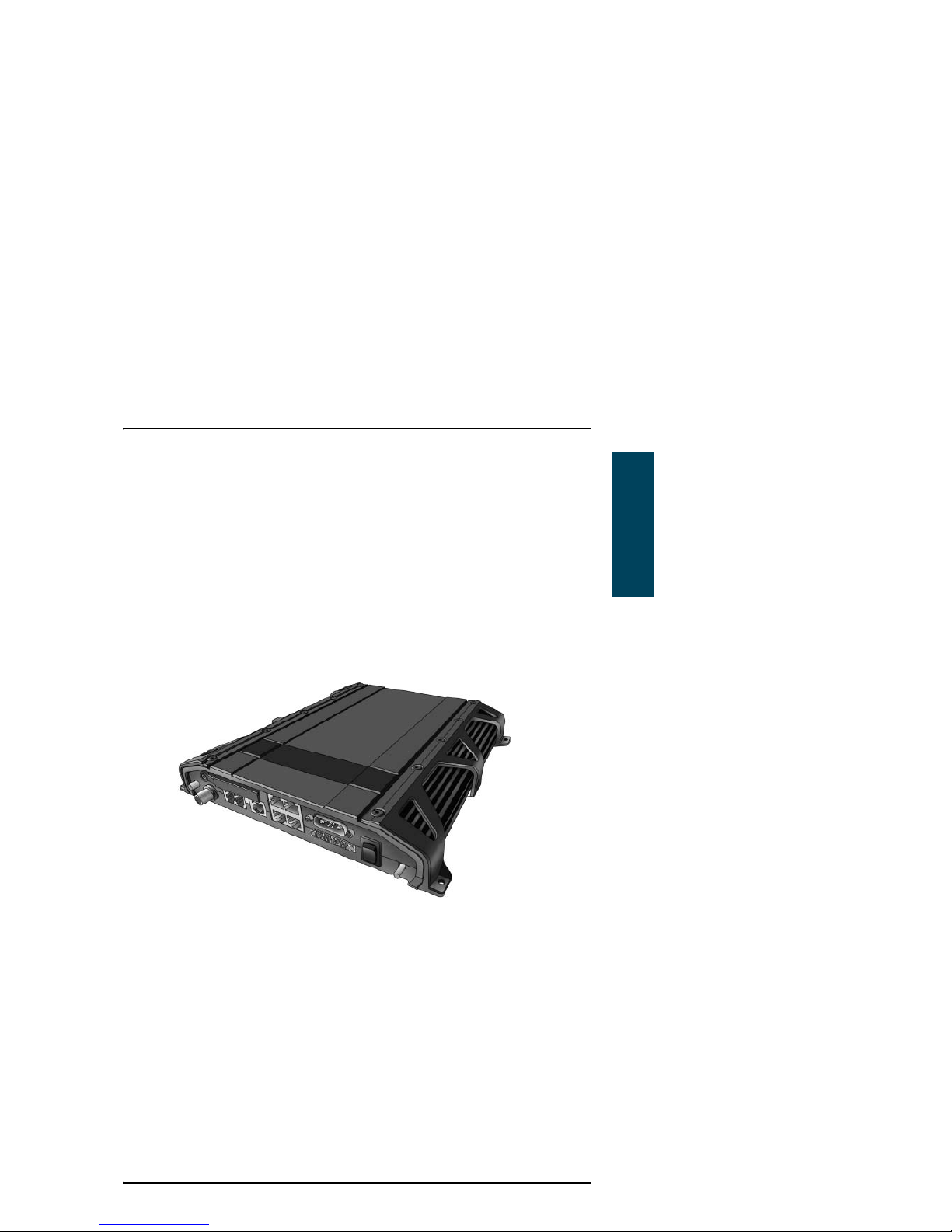
SAILOR FleetBroadband terminal
Overview
Whether you have purchased a SAILOR 500 FleetBroadband system or a
SAILOR 250 FleetBroadband system, the terminal is basically the same. For
this reason this section covers both systems.
The SAILOR FleetBroadband Terminal is the controlling unit in the
SAILOR FleetBroadband system. It contains all user interfaces and LED
indicators and stores configuration data.
Page 24
Chapter 1: Introduction
8Main units
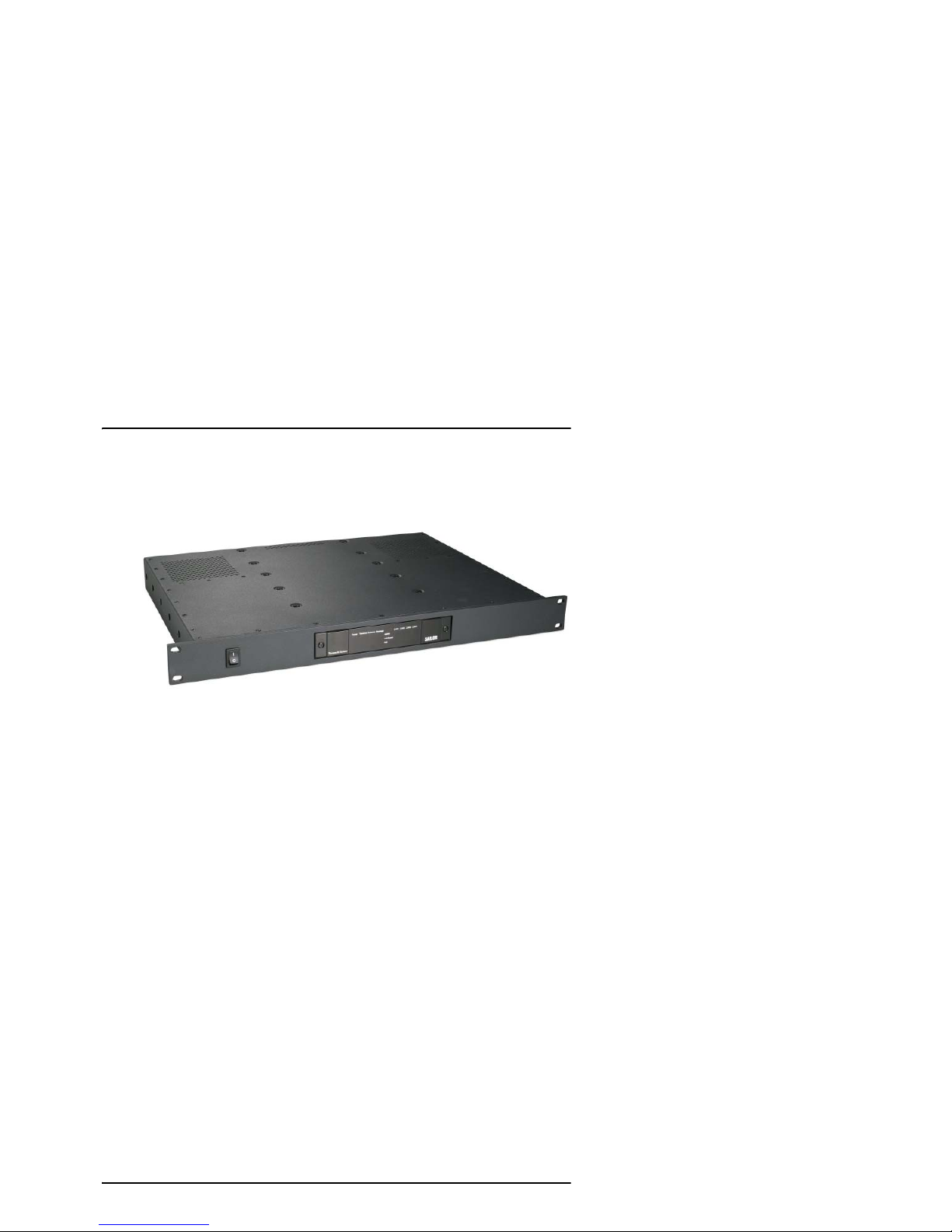
The terminal is also available in a 19” Rack version. The 19” Rack terminal is
the same as the basic version, except for the housing which fits in a 19” rack
and has an additional power switch on the front panel.
For information on how to install the terminal, refer to the installation manual.
Tools for setup and daily use
The Thrane IP Handset can be used for displaying status, accessing a subset of
controls and views, starting a streaming session and entering the PIN code for
the terminal. The Thrane IP handset connects to the LAN interface of the
terminal. For information on how to use the handset, see the user manual for
the Thrane IP handset.
The built-in web interface in the terminal is used for easy configuration and
daily use. The web interface is accessed from a computer connected to the
terminal, using an Internet browser. No installation of software is needed.
For details on the web interface, see Chapter 4, Using the web interface.
SIM card
The terminal has a SIM (Subscriber Identity Module) slot located in the
connector panel behind a small cover plate.
The terminal requires a dedicated FleetBroadband SIM card, which you get
from your Airtime Provider.
The system requires a SIM card to go online and to access the settings of the
terminal. However, using the web interface you can view the Dashboard and
upload software without inserting a SIM card.
Page 25
Chapter 1: Introduction
Main units 9
1111
Introduction
Thrane IP handset and cradle
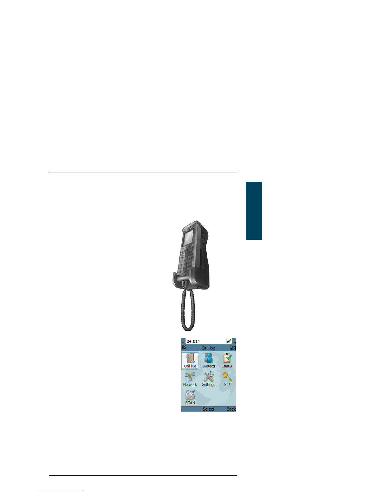
Thrane IP handset
The Thrane IP Handset communicates using
Internet Protocols (IP). The handset is not
strictly dedicated to the
SAILOR FleetBroadband system, but can
also be used in a public network as a
standard IP telephone.
The Thrane IP handset is powered directly
from the LAN interface using Power over
Ethernet (PoE).
When connected to the terminal the Thrane IP
handset provides a dedicated BGAN menu with a
subset of the terminal configuration options.
For more information on the functions of the
Thrane IP handset, refer to the user manual for
the Thrane IP handset.
Thrane IP cradle
The Thrane IP cradle serves as a holder for the Thrane IP handset. The cradle
connects to the coil cord from the handset and, using an Ethernet cable, to the
terminal. You can mount the cradle on a wall or a desktop.
Page 26

Chapter 1: Introduction
10 The Inmarsat BGAN system
The Inmarsat BGAN system
What is BGAN?
The Broadband Global Area Network (BGAN) is a mobile satellite service that
offers high-speed data up to 492 kbps and voice telephony. BGAN enables
users to access e-mail, corporate networks and the Internet, transfer files and
make telephone calls.
The Inmarsat FleetBroadband service
FleetBroadband is a maritime communications service offered in the BGAN
system. Based on 3G standards, FleetBroadband provides cost-effective
broadband data and voice simultaneously.
Page 27

Chapter 1: Introduction
The Inmarsat BGAN system 11
1111
Introduction
Coverage
The Inmarsat® BGAN services are based on geostationary satellites situated
above the equator. Each satellite covers a certain area (footprint). The
coverage map below shows the footprints of the BGAN system. For updated
information on coverage, see Inmarsat’s home page at inmarsat.com.
This map depicts Inmarsat’s expectations of coverage post repositioning of its I-4 satellites. This
map does not represent a guarantee of service. The availability of service at the edge of coverage
areas fluctuates depending on various conditions. www.inmarsat.com
0°
10°
20°
30°
40°
50°
60°
70°
80°
90°
10°
20°
30°
40°
50°
60°
70°
80°
90°
0°20°40°60°80°100°120°140°160°180° 20° 40° 60° 80° 100° 120° 140° 160° 180°
Inmarsat’s I4 satellite coverage
0 degrees
Note
The map above shows Inmarsat’s expectations of coverage, but does
not represent a guarantee of service. The availability of service at the
edge of coverage areas may fluctuate.
Page 28
Chapter 1: Introduction
12 The Inmarsat BGAN system
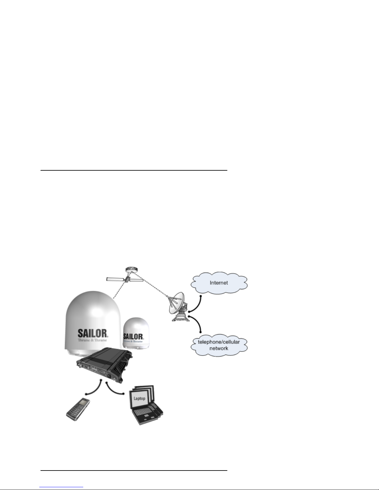
Overview of the BGAN FleetBroadband system
A complete BGAN FleetBroadband system includes the
SAILOR FleetBroadband terminal with connected peripherals, a
SAILOR 500 FleetBroadband antenna or a SAILOR 250 FleetBroadband
antenna, the BGAN satellite, and the Satellite Access Station (SAS). The
satellites are the connection between your terminal and the SAS, which is the
gateway to the worldwide networks (Internet, telephone network, cellular
network, etc.).
SAILOR
FleetBroadband
Satellite Access Station
(SAS)
Satellite
Packet Switched Network
Circuit Switched Network
SAILOR 250
FleetBroadband
antenna
terminal
IP Handset
SAILOR 500
FleetBroadband
antenna
Page 29

Chapter 1: Introduction
The Inmarsat BGAN system 13
1111
Introduction
The BGAN services supported by SAILOR FleetBroadband
Supported services
The services currently supported by the SAILOR FleetBroadband comprise:
• A Packet-Switched (PS) connection to the Internet
• A Circuit-Switched (CS) dialed connection for voice, fax or data
• Short Messaging Service (SMS)
•Multi-voice
•Voice Distress
Packet data service
The BGAN network supports different classes of data connection to the
Internet.
•Using a Standard IP connection several users can share the data
connection simultaneously. This type of connection is ideal for e-mail, file
transfer, and Internet and intranet access. The user pays for the amount of
data sent and received.
•Using a Streaming IP connection you get an exclusive high-priority
connection ensuring seamless transfer of data. This type of connection is
ideal for time critical applications like live video over IP. The 8 and 16 kbps
connections are well suited for Voice over IP. The user pays for the duration
of the connection (per minute charge).
Note
The BGAN system supports maximum 11 concurrent Packet Switched
connections at a time per SAILOR FleetBroadband system.
Page 30

Chapter 1: Introduction
14 The Inmarsat BGAN system
Circuit-Switched (dialed) service
The following types of circuit-switched connection are available:
• Standard Voice. A low-tariff connection for voice only. The voice signal is
compressed to 4.0 kbps, which reduces the bandwidth use and
consequently the tariff.
• 3.1 kHz Audio. A high quality connection which can be used for Premium
Voice or G3 fax. The signal is uncompressed 3.1 kHz audio, which allows for
optimum voice quality.
• ISDN. A high quality connection which can be used for voice (3.1 kHz
Audio), G4 fax or 64 kbps UDI/RDI data.
SMS service
The BGAN system provides a Short Messaging Service (SMS) for sending and
receiving SMS messages to and from the terminal.
Multi-voice service (optional)
Normally, the BGAN system only supports one call at a time per
SAILOR FleetBroadband system. When you subscribe to the optional Multivoice service and enable it in your system, you can have up to 9 concurrent
calls.
To use the Multi-voice service you must enable Multi-voice and enter the APN
for Multi-voice in the web interface of the SAILOR FleetBroadband terminal.
For information on how to set up Multi-voice, see Multi-voice on page 196.
Voice Distress service (optional)
The Voice Distress service uses FleetBroadband to provide priority call access
as soon as the red distress button on the alarm panel is pressed. The caller
will then be connected to an operator at one of three Maritime Rescue
Coordination Centres (MRCCs) strategically located around the globe.
To use the Voice Distress service you must first have it included in your airtime
subscription, acquire a SAILOR 3771 Alarm Panel, enable Voice Distress in your
Page 31

Chapter 1: Introduction
The Inmarsat BGAN system 15
1111
Introduction
terminal and assign a Thrane IP handset in the web interface of the
SAILOR FleetBroadband terminal.
Supplementary services
The BGAN system also provides the following supplementary services:
•Call hold
• Call waiting
• Call forwarding
•Voice mail
•Call barring
Page 32

Chapter 1: Introduction
16 The Inmarsat BGAN system
Service limitations
SIM lock
The supplier may have locked the SIM card to a specific provider. For further
information, contact your supplier.
Limitations in available services
The services available depend on your airtime subscription. Your SIM card
may not allow for all the services described in this manual.
For Multi-voice, the maximum number of concurrent calls depends on the
terminal type and the available bandwidth and network conditions.
Also, some services may not be available at the edge of coverage areas, i.e. in
low elevations. The lines in the coverage map below enclose the areas with an
elevation angle towards the satellite of 0, 20 and 45 degrees.
For further information on coverage, please refer to the Inmarsat home page
at inmarsat.com.
This map depicts Inmarsat’s expectations of coverage post repositioning of its I-4 satellites. This
map does not represent a guarantee of service. The availability of service at the edge of coverage
0°
10°
20°
30°
40°
50°
60°
70°
80°
90°
10°
20°
30°
40°
50°
60°
70°
80°
90°
0°20°40°60°80°100°120°140°160°180° 20° 40° 60° 80° 100° 120° 140° 160° 180°
Inmarsat’s I4 satellite coverage
45 degrees
20 degrees
0 degrees
Page 33

Chapter 1: Introduction
Services and interfaces 17
1111
Introduction
Services and interfaces
The following table shows which equipment and interfaces you can use to
access the services listed in the left column.
Service
Interface on the terminal
Phone/Fax LAN (PoE) ISDN
3.1 kHz Audio
a
Analog
telephone
IP handset ISDN telephone
G3 Fax machine G4 Fax machine
in G3 mode
Standard Voice
Analog
telephone
IP handset ISDN telephone
Data, UDI
a
or
RDI
a. Notes for SAILOR 250 FleetBroadband: UDI data is not available. In low
elevations, < 20°, 3.1 kHz Audio is not available. Refer to Service limitations on
page 16.
G4 fax machine
or computer with
ISDN modem
Data over IP
Computer
SMS
Computer using
web interface
Page 34

Chapter 1: Introduction
18 Services and interfaces
Page 35

19
Chapter 2
2222
Getting started
Getting started 2
This chapter describes how to start up the system and make the first call or
data session. It has the following sections:
• Before you start
• Starting up the terminal
• Connecting the Thrane IP handset
• Connecting a computer
• Entering the SIM PIN for the terminal
• Registering with the BGAN network
• Making the first call
• Standard connection to the Internet (default)
For information on how to install the system, insert SIM card and connect
cables, refer to the installation manual for the SAILOR FleetBroadband
systems.
Page 36

Chapter 2: Getting started
20 Before you start
Before you start
Operation at high temperatures
If the terminal is installed in a location where the ambient temperature may
exceed 45C, we recommend placing the terminal where unintentional contact
is avoided. Note that the maximum allowed ambient temperature is 55°C.
If the maximum ambient temperature does not exceed 45C, the terminal can
be placed in a public area.
For further information on installation, refer to the installation manual for the
SAILOR FleetBroadband systems.
Caution! In very high ambient temperatures, do not touch
areas of the terminal that are marked with this
symbol.
Page 37

Chapter 2: Getting started
Before you start 21
2222
Getting started
Connector panel
The drawings below show the connector panel of each terminal version. The
only difference is the Terminal block on the 19” Rack terminal.
Connector panel on SAILOR FleetBroadband terminal:
Connector panel on SAILOR FleetBroadband, 19” Rack terminal:
For information on how to connect to each interface, refer to the installation
manual for the SAILOR FleetBroadband systems.
Grounding stud
Power
switch
I/O
DC input
4 x LAN w. PoE
SIM slot
L-Band ISDNPhone/Fax 1Antenna
Reset button
Phone/Fax 2
Grounding
Power
switch
I/O
DC input
4 x LAN w. PoE
SIM slot
L-Band ISDNPhone/Fax
Antenna
Reset button
Phone/Fax
Terminal
block forstud
front switch
#1
#2
Page 38

Chapter 2: Getting started
22 Starting up the terminal
Starting up the terminal
SIM card
Note that the SAILOR FleetBroadband terminal requires a SIM card dedicated
to FleetBroadband. The terminal can only access the BGAN network when the
right type of SIM card is installed. For information on how to insert the SIM
card, refer to the installation manual.
Switching on the terminal
Using the Power switch
To switch on the terminal, use the On/Off switch in the connector panel. It
normally takes one or two seconds for the terminal to switch on.
Note
If you have the 19” Rack variant of the SAILOR FleetBroadband
terminal, you can use the on/off switch in the front panel. See the
next section 19” Rack terminal: Using the front power switch.
Page 39

Chapter 2: Getting started
Starting up the terminal 23
2222
Getting started
19” Rack terminal: Using the front power switch
If you have the 19” Rack variant of the SAILOR FleetBroadband terminal, flip
the switch in the front panel to “1” to switch on the terminal.
Note
To be able to use the power switch on the front panel, you must
leave the On/Off switch in the connector panel in the On position.
Page 40

Chapter 2: Getting started
24 Starting up the terminal
Using the ignition system
Normally the ignition function is not used in maritime installations. Instead
you may want to use the remote on/off function described in the next section.
If you have connected the ignition system of your vessel to the I/O connector,
you may leave the power switch in the “on” position and the terminal will
switch on/off when you start/stop the engine of your vessel.
When the engine is stopped the terminal is in standby mode. The standby
current is max. 15 mA when the ignition is off. For information on how to
connect to the Ignition pins in the I/O connector, refer to the installation
manual for the SAILOR FleetBroadband system.
You must set up the ignition function in the web interface. For further
information, see Configuring the I/O interface on page 138.
Using a remote on/off switch
If an external switch is connected to the remote on/off pins in the DC
connector, you may leave the power switch in the connector panel in the “on”
position and use the remote switch to turn the terminal on and off. When the
remote switch is off, the terminal is off. However, if you leave the power switch
on the terminal in the “on” position, you can always switch the terminal back
on with the remote switch. The standby current when the remote switch is off
is max. 2 mA. For further information on the remote on/off function, refer to
the installation manual for the SAILOR FleetBroadband systems.
Note
If you have the 19” Rack terminal, you must leave both power
switches in the “on” position to make use of the ignition function.
Note
In some cases, the system may reboot after power-on because of the
high start-up current.
Note
In the 19” Rack version of the terminal the remote on/off function is
normally not available, because it is used for the front switch.
Page 41

Chapter 2: Getting started
Starting up the terminal 25
2222
Getting started
Power up completed
When the terminal is switched on, the Power indicator in the LED panel of the
terminal lights green.
You can now access the terminal settings, but the terminal is not ready for
making calls or running data sessions until the system is registered on the
BGAN network. You may have to enter a SIM PIN before the system can
register. For further information, see Entering the SIM PIN for the terminal on
page 28 and Registering with the BGAN network on page 32.
To switch off the terminal flip the Power switch back. It takes 5 to 10 seconds
to power down the terminal. Alternatively use the ignition or remote on/off
function described above.
Page 42

Chapter 2: Getting started
26 Connecting the Thrane IP handset
Connecting the Thrane IP handset
Power supply (PoE)
The Thrane IP Handset is powered from the LAN interface, using Power over
Ethernet. The total output power from all 4 interfaces is
• 64 W at 24 V DC power supply
• 32 W at 12 V DC power supply
All interfaces can support devices of power class 1, 2 and 3 (4, 7 and 15.4 Watt),
as long as the total power consumption does not exceed the above limits. If
the limits are exceeded, the LAN ports are prioritised so that LAN port 1 has the
highest priority.
In case of power hold-up (failure on input power), PoE will be turned off
completely.
Starting up the Thrane IP Handset
The following procedure is for the Thrane IP Handset. The procedure may be
different for another type of IP handset.
To start up the Thrane IP Handset, do as follows:
1. Connect the Ethernet cable from the Thrane IP Handset/cradle to one of the
LAN (PoE) connectors on the terminal as described in the user manual for
the handset.
2. The handset starts up automatically.
When the display shows this symbol in the upper right corner, the
handset is ready for making a call.
Note
By default, a handset connected to the LAN interface on the terminal
is automatically registered in the terminal and assigned the first
available local number. For information on how to configure
handsets, see Connecting and configuring IP handsets on page 130.
Page 43

Chapter 2: Getting started
Connecting a computer 27
2222
Getting started
If the handset is not ready for making calls, it may be because the BGAN
terminal is waiting for a SIM PIN. To check this, enter the handset menu
system and select BGAN > Status > PIN status.
You can enter the SIM PIN using the Thrane IP handset. For details, see
Entering the SIM PIN using a phone or Thrane IP handset on page 29.
Connecting a computer
Before connecting to the LAN interface
For the LAN interface to work without any further setup, the connected
computer must be set up to obtain an IP address and a DNS server address
automatically.
To check this on your computer (Windows XP), do as follows:
1. Go to Start > Settings > Control Panel > Network Connections.
2. Right-click on the LAN connection you want to use.
3. Select Properties.
4. Highlight Internet Protocol (TCP/IP).
5. Click Properties.
6. Make sure that the following is selected:
• Obtain an IP address automatically
• Obtain DNS server address automatically
Connecting a computer to the LAN interface
To connect a computer to the LAN interface, do as follows:
1. Power up your computer.
2. Connect your LAN cable between the network connector on your computer
and one of the LAN connectors on the terminal.
Page 44

Chapter 2: Getting started
28 Entering the SIM PIN for the terminal
3. When the computer and the terminal are ready, check the connection e.g.
by accessing the built-in web interface of the terminal with your browser.
For further information, see Accessing the web interface on page 82.
You may have to disable the Proxy server settings in your browser. For
further information, see Proxy settings when accessing the web interface
on page 81.
For information on how to connect to the Internet, see Standard connection to
the Internet (default) on page 37.
For information on how to configure the LAN interface on the terminal, see
Configuring the LAN interface on page 107.
Entering the SIM PIN for the terminal
Do you need a SIM PIN?
Depending on your SIM card, you may have to enter a SIM PIN to use the
system. Your SIM PIN is supplied with your SIM card. You can enter the PIN
using a standard phone or ISDN phone, the Thrane IP handset or the web
interface.
For information on how to connect the Thrane IP handset or computer you are
going to use, see Connecting a computer to the LAN interface on page 27 or
Connecting the Thrane IP handset on page 26.
Note
Using an Administrator user name and password you can change
the PIN and enable or disable the use of a PIN. For further
information, see Setting up the use of SIM PIN in the terminal on
page 185.
Page 45

Chapter 2: Getting started
Entering the SIM PIN for the terminal 29
2222
Getting started
Entering the SIM PIN using a phone or Thrane IP handset
To enter the SIM PIN
If you have a phone connected to the terminal, you can use it to enter the SIM
PIN for the terminal at start up.
Do as follows:
• For an analogue or ISDN phone:
Pick up the phone. When the terminal is waiting for a PIN, you will hear 2
beeps - pause - 2 beeps - etc.
Dial <PIN> followed by #.
When you hear a “busy” tone or a dialling tone, the PIN has been
accepted and you can hang up or dial a number.
• For the Thrane IP Handset:
Select the BGAN menu, select Enter PIN and enter the administrator user
name and password for the terminal. Then enter the PIN for the terminal.
Note that the menu item “Enter PIN” is only available if the terminal is
waiting for a PIN.
Wrong SIM PIN
Analogue phone or ISDN phone:
If, instead of the busy tone or dialling tone, you continue to hear 2 beeps pause - 2 beeps - etc., it means the SIM PIN was not accepted. Check that you
have the correct PIN and try again.
If a wrong PIN has been entered three times in the terminal, you will hear 3
beeps - pause - 3 beeps - etc. This means you have to enter the PUK (PIN
Unblocking Key) provided with your SIM card.
After entering the PUK, you must enter a new PIN of your own choice (4 to 8
digits long).
Dial the following:
<PUK> * <New PIN> * <New PIN> followed by # or off-hook key.
Example: If the PUK is 87654321 and the new PIN is 1234, dial
87654321 * 1234 * 1234 followed by # or off-hook key.
Page 46

Chapter 2: Getting started
30 Entering the SIM PIN for the terminal
If you enter 10 wrong PUKs, the SIM card will no longer be functional. Contact
your Airtime Provider for a new SIM card.
Thrane IP handset:
After having entered the user name and password for the terminal you have 3
attempts to enter the SIM PIN, before you are asked to enter the PUK (Pin
Unblocking Key). The PUK is supplied with the SIM card for your terminal.
Enter the PUK followed by a new PIN of your own choice. The PIN must be
from 4 to 8 digits long.
If you enter a wrong PUK 10 times, the SIM card will no longer be functional,
and you have to contact your Airtime Provider for a new SIM card.
Entering the SIM PIN using the web interface
To enter the SIM PIN
Do as follows:
1. On a computer connected to the terminal, open your browser and enter
http://ut.bgan or the IP address of the terminal in the address bar (default
IP address: http://192.168.0.1).
Page 47

Chapter 2: Getting started
Entering the SIM PIN for the terminal 31
2222
Getting started
If your SIM card uses a PIN and the PIN has not yet been entered, the web
interface will open on the PIN page.
2. Type in the PIN and click OK.
When the PIN is accepted, the web interface opens the Dashboard and is
ready for use. If the PIN is not accepted, see the next section Wrong PIN.
For further information on the web interface refer to Using the web interface
on page 79.
Wrong PIN
You have 3 attempts to enter the PIN in the web interface, before you are
asked to enter the PUK (Pin Unblocking Key). The PUK is supplied with your
SIM card.
Enter the PUK followed by a new PIN of your own choice. The PIN must be
from 4 to 8 digits long.
If you enter a wrong PUK 10 times, the SIM card will no longer be functional,
and you have to contact your Airtime Provider for a new SIM card.
Page 48

Chapter 2: Getting started
32 Registering with the BGAN network
Registering with the BGAN network
Registration procedure
When the SIM PIN is accepted by the terminal, the SAILOR FleetBroadband
system automatically starts the registration procedure on the BGAN network.
You can monitor the registration procedure by looking at the Antenna and
Terminal indicators in the LED panel of the terminal.
Note that the registration procedure may take several minutes. The table in
the next section shows the normal sequence when registering.
Page 49

Chapter 2: Getting started
Registering with the BGAN network 33
2222
Getting started
LED indications during the registration procedure
This table shows how the startup procedure is signalled with the light
indicators. If an error occurs, the indicators will light yellow or red, depending
on the severity of the error. For further information on the indicators, see Light
indicators on page 219.
Status Antenna indicator Terminal indicator
The antenna is starting up Flashing slowly green Flashing green
The antenna is
performing a sky scan
Flashing rapidly green Flashing green
The antenna is tracking Steady green Flashing green
The terminal is
registering on the
network
Steady green Flashing green
The system is registered
and ready for use.
Steady green Steady green
Page 50

Chapter 2: Getting started
34 Registering with the BGAN network
Indications in the web interface
The dashboard in the web interface also shows the status during and after
registration. When the system is ready, the Antenna status field shows
Tracking and the Status field shows Ready (unless a call or data session is
active). Click Refresh to update the screen.
Page 51

Chapter 2: Getting started
Making the first call 35
2222
Getting started
Making the first call
When the Antenna and Terminal indicators in the LED panel on the terminal
both light steady green, you are ready to make or receive the first call. The
following sections provide a short guide to making calls. For more detailed
information, see Making or receiving a phone call on page 48.
Making a call from the terminal
To make a call from a phone connected to the terminal, dial
00 <country code> <phone number> followed by # or off-hook key.
Example: To call Thrane & Thrane in Denmark (+45 39558800) from an
analogue phone, dial 00 45 39558800 #
Making a call to the terminal
To make a call to a phone connected to the terminal, dial
+ <Mobile number>
• + is the international call prefix
1
used in front of the country code for
international calls.
Note
By default all phones connected to the terminal will ring on
incoming calls. However, you can configure the behaviour of the
interfaces using the web interface (see the relevant interface in
Setting up the interfaces on page 106). You can also set up a local
exchange function in the terminal so that you can call a specific
phone connected to the terminal. See Setting up the local exchange
function on page 128.
1. The plus sign indicates the code required to dial out of one's country code area,
such as 00 in most of Europe, 011 in the United States, and other short codes in
other parts of the world.
Page 52

Chapter 2: Getting started
36 Making the first call
• Mobile number: The mobile number of the terminal/handset you are
calling. The first part of the number is always 870, which is the “country
code” for the BGAN system.
Example: If you are calling from Denmark and the mobile number for
Standard Voice is 870772420567 on your terminal, and you want to
make a Standard call to the terminal, dial 00 870 772420567.
If the mobile numbers are listed in the web interface, you can look them up by
selecting PHONE BOOK > Mobile numbers. If the numbers are not listed, refer
to the documents provided with your airtime subscription. See Viewing and
editing the mobile numbers on page 94.
Making a call from one terminal to another
To make a call from one terminal to another, dial 00 <Mobile number>.
Page 53

Chapter 2: Getting started
Standard connection to the Internet (default) 37
2222
Getting started
Standard connection to the Internet (default)
By default, the terminal does not automatically connect to the Internet when
you connect your computer or other equipment to the LAN interface. You must
activate your connection from the Dashboard in the web interface or from the
Thrane IP Handset with local number 0501 (master handset).
Activating the connection from a computer (web interface)
To activate the connection from a connected computer, do as follows:
1. Access the web interface by opening your browser and entering
http://ut.bgan or the IP address of the terminal in the address bar.
“http://ut.bgan” translates into the IP address of the terminal (if your
computer is set up as described in Before connecting to the LAN interface
on page 27). The default IP address is 192.168.0.1.
2. Click Start Standard under PROFILES ON LAN at the bottom of the page.
3. Check the connection, e.g. by entering a web site.
The field ONGOING DATA SESSIONS will show the IP address for the data
session you started.
Note
This section only describes a Standard Internet connection with
default settings on the terminal. For information on other scenarios,
see Connecting to the Internet on page 68.
Page 54

Chapter 2: Getting started
38 Standard connection to the Internet (default)
Activating the connection using the Thrane IP Handset (only handset
number 0501)
To activate the connection using the Thrane IP Handset, do as follows:
1. Connect the Thrane IP Handset to one of the LAN ports (preferably port 1).
The handset starts up automatically.
2. Select Menu > BGAN in the handset.
3. Select Connect.
4. Use the left/right keys to find the network user group for the application
you want to start.
5. Press Start to start the connection.
A confirmation window is displayed.
6. Press Ye s to continue.
The Thrane IP Handset sends a command to the terminal to start the
selected connection.
7. Check the connection, e.g. by entering a web site from a connected
computer.
Page 55

39
Chapter 3
3333
Operating the system
Operating the system 3
This chapter describes how to use the SAILOR FleetBroadband systems. It has
the following sections:
• General
• Using a phone or fax machine
• Multi-voice (optional)
• Voice Distress (optional)
• Using a computer
• Using the Thrane IP handset
This chapter does not describe advanced configuration of interfaces. For this
type of information, refer to the “Configuring...” sections for the interfaces in
Chapter 4, Using the web interface.
General
Tools for setup and use
Overview
You can use the Thrane IP Handset for viewing status, using the phone book of
the terminal and for entering the PIN, but for enhanced use and for
configuration of interfaces, you must connect a computer.
With a computer and a browser, you can use the built-in web interface to set
up the terminal.
Page 56

Chapter 3: Operating the system
40 General
The Thrane IP handset
When you connect the Thrane IP Handset to one of the LAN (PoE) connectors
on the terminal you can use the handset display and keypad to enter the PIN
or to view the status of the terminal.
The menu system in the Thrane IP handset includes the following items for the
terminal:
•BGAN menu:
• Selecting, starting and stopping your data connections
• Viewing C/No (signal strength) for the system
• Viewing status (“Ready”, “Registering” etc.) for the system
• Viewing the software version of the terminal
• Entering the PIN and PUK for the terminal
• Viewing active events
• Viewing GPS status
•Contacts:
• Inclusion of the terminal phone book (not editable) in the Thrane IP
handset Contacts
• SIP (Session Initiation Protocol):
• Selecting/viewing/configuring the SIP profile used for communication
with the BGAN terminal
• Date and time:
• Possibility of using UTC time received from the BGAN satellite
For further information, see the user manual for the Thrane IP handset.
Page 57

Chapter 3: Operating the system
General 41
3333
Operating the system
The web interface of the terminal
The web interface is a built-in web server for setting up and controlling the
terminal, using a connected computer with a browser.
With the web interface you can:
• Enter the SIM PIN for the terminal
•DASHBOARD page:
• start and stop data sessions
• view information on calls to/from the terminal
• view status of the terminal and antenna
• view properties of the terminal and antenna
• CONNECT page:
• start and stop data sessions for all network user groups connected to
the terminal (requires administrator password)
• PHONE BOOK page:
• view and edit the phone book
•MESSAGES page:
• send and receive SMS messages
• CALLS page:
• view the call log (outgoing, received and missed calls and data)
• SETTINGS page:
• set up the interfaces of the terminal
• set up call services
• upload software
• set up network user groups (requires administrator password)
• select the satellite to use for connection to the BGAN network
• set the language in the web interface
• ADMINISTRATION page:
• set up data limits
• set up data profiles and traffic flow filters
Page 58

Chapter 3: Operating the system
42 General
• change the SIM PIN for the terminal
• set up user rights (requires administrator password)
• set up remote management and activation
• set up restricted dialling
• set up Multi-voice
• set up Voice Distress
For information on how to use the web interface, see Using the web interface
on page 79.
Page 59

Chapter 3: Operating the system
General 43
3333
Operating the system
Services and interfaces
The following table shows which equipment and interfaces you can use to
access the services listed in the left column.
Service
Interface on the terminal
Phone/Fax LAN (PoE) ISDN
3.1 kHz Audio
a
Analog
telephone
IP handset ISDN telephone
G3 Fax machine G4 Fax machine
in G3 mode
Standard Voice
Analog
telephone
IP handset ISDN telephone
Data, UDI
a
or RDI
a. Notes for SAILOR 250 FleetBroadband: UDI data is not available. In low
elevations, < 20°, 3.1 kHz Audio is not available. Refer to Service limitations on
page 16.
G4 fax machine
or computer with
ISDN modem
Data over IP
Computer
SMS
Computer
using web
interface
Page 60

Chapter 3: Operating the system
44 Using a phone or fax machine
Using a phone or fax machine
Available interfaces
Three types of voice equipment connect to the terminal:
Standard analogue phone or G3 fax machine: The terminal has two phone
connectors for connecting standard analogue phones or fax machines.
IP handset: The terminal has four LAN connectors with Power over Ethernet for
connecting IP handsets or other IP equipment. For details on the features and
functions of the Thrane IP Handset, refer to the user manual for the handset.
ISDN phone or G4 fax machine: The terminal has one ISDN connector for
connecting an ISDN phone, a modem or a fax machine. Note that only
SAILOR 500 FleetBroadband supports G4 fax (UDI).
For information on how to connect to the interfaces, see the installation
manual for the SAILOR FleetBroadband systems.
Phone/Fax 1 Phone/Fax 2 ISDN LAN
Page 61

Chapter 3: Operating the system
Using a phone or fax machine 45
3333
Operating the system
Selecting the call type
Definition
The phone connection can use one of the following call types:
• Standard Voice, which is a low-tariff voice connection compressed to
4.0 kbps
• 3.1 kHz Audio, which is a high quality connection used for Premium Voice
or G.3 fax
• UDI or RDI (only on ISDN interface), which is used for G4 fax or data
In the web interface you can set up which type of connection to use by default
when you make or receive a call from the Phone/Fax or ISDN interface or from
an IP handset connected to the LAN interface. Standard Voice is selected by
default.
When connecting a fax to the Phone/Fax interface you must use 3.1 kHz Audio.
Example: If you always have a fax connected to the same Phone/Fax
interface you can set this interface to 3.1 kHz Audio only. This will
mean that if an incoming Standard Voice call is received, this
Phone/Fax interface will not ring.
When connecting a G4 fax or a modem to the ISDN interface in the
SAILOR 500 FleetBroadband system you must use UDI.
Selecting the default outgoing call type
To select the default call type for outgoing calls, do as follows:
• ISDN. Select the call type in the web interface under SETTINGS > ISDN.
For further information, see Configuring the ISDN interface on page 116.
Note
UDI and RDI are not available with the SAILOR 250 FleetBroadband
system, so you cannot connect a G4 fax machine nor a modem to the
ISDN interface on the SAILOR 250 FleetBroadband system.
Page 62

Chapter 3: Operating the system
46 Using a phone or fax machine
• Phone/Fax. Select the call type for each port in the web interface under
SETTINGS > Phone/Fax. For further information, see Configuring the
Phone/Fax interface on page 114.
• IP handset. Select the call type for each handset in the web interface under
SETTINGS > IP Handset > Call settings. For further information, see Setting
the call types for IP handsets on page 132.
Overriding the default outgoing call type
To override the default setting for a specific outgoing call, do as follows:
•To use Standard Voice for the call,
dial 1* before the number.
•To use 3.1 kHz Audio for the call,
dial 2* before the number.
Example: To make a call to Thrane & Thrane in Denmark (+45 39558800),
forcing the connection to use Standard Voice, dial 1* 0045
39558800 followed by # if calling from an analogue or ISDN phone,
or off-hook key if calling from an IP handset.
Note
This will not change the default call type, only the type used for the
ongoing call.
Page 63

Chapter 3: Operating the system
Using a phone or fax machine 47
3333
Operating the system
Phone numbers for incoming calls
The mobile numbers for your system are listed in your airtime subscription.
For example, you may have
• 1 number for Standard Voice
•1 number for 3.1 kHz Audio
• 1 number for UDI data
•1 number for RDI data
If you have subscribed to the optional Multi-voice feature you may also have
Additional numbers, which can be assigned to individual handsets. For further
information, see Additional numbers for Multi-voice on page 64.
If the mobile numbers are listed in the web interface, you can look them up as
follows:
Connect a computer, access the web interface and select PHONE BOOK >
Mobile numbers. For further information, see Viewing and editing the mobile
numbers on page 94.
For information on how to make a call to the terminal, see Making a call to the
terminal on page 50.
Selecting the incoming call type
To select which call types are accepted for an incoming call, use a computer
and the web interface. If you are using Multi-voice, see Handset contexts on
page 61.
• ISDN. Select the call type under SETTINGS > ISDN.
For further information, see Configuring the ISDN interface on page 116.
• Phone/Fax. Select the call type for each port under SETTINGS > Phone/Fax.
For further information, see Configuring the Phone/Fax interface on
page 114.
Note
The call type you are using must be selected in the web interface
(refer to the next section).
Page 64

Chapter 3: Operating the system
48 Using a phone or fax machine
• IP handset. Select the call type for each handset in the web interface under
SETTINGS > IP Handset > Call settings. For further information, see Setting
the call types for IP handsets on page 132.
Making or receiving a phone call
Making a call
You have different options for making a call:
• Short Dial. If the number is in the phone book of the terminal, you can use
the Short Dial number, which is found in the first column of the phone book
in the web interface. See Short dial on page 92.
Simply dial 00 <Short Dial> followed by # or off-hook key.
Example: To call entry number 4 in the phone book,
dial 004 followed by # or off-hook key.
• Manual Dial. To make a call, dial
00 <country code> <phone number> followed by # or off-hook key.
Example: To call Thrane & Thrane in Denmark (+45 39558800) from an
analogue or ISDN phone, dial 00 45 39558800 #
• Call from phone book or call log (only Thrane IP handset).
• Enter the phone book of the Thrane IP handset, scroll to the wanted
number and press the off-hook key, or
• press the off-hook key from the main screen to display the latest calls in
the call log. Then scroll to the wanted number and press the off-hook
key again.
Note that this is the call log of the Thrane IP handset, not of the
terminal.
Note
If one call is already active, you can only make a second call if you
have Multi-voice in your subscription and it is enabled. For details
on how to set up Multi-voice using the web interface, see Multi-
voice on page 196.
Page 65

Chapter 3: Operating the system
Using a phone or fax machine 49
3333
Operating the system
If there was an error establishing the connection, refer to the Troubleshooting
Guide on page 209.
If you are using the Thrane IP handset, the handset may show an error
message.
Depending on the type of error, the web interface may also show an error
message. See Viewing the Event list or the Event log on page 202.
Receiving a call
By default, all devices connected to the Phone/Fax interface, the ISDN
interface or the LAN (PoE) interface will ring when one of the mobile numbers
is called. Note, however, that this depends on the call type settings and on the
local exchange settings. Refer to Selecting the incoming call type on page 47
and Setting up the local exchange function on page 128.
If you are using Multi-voice there are more options for setting up how to
handle incoming calls. See Handset contexts on page 61.
Call log
Information of outgoing calls, received calls and missed calls is stored in the
call log of the terminal. You can view the call log in the web interface under
CALLS. For further information, see Viewing the lists of calls and data sessions
on page 97.
Page 66

Chapter 3: Operating the system
50 Using a phone or fax machine
Making a call to the terminal
To make a call to a phone connected to the terminal, dial
+ <Mobile number>
• + is the international call prefix
1
used in front of the country code for
international calls.
• Mobile number. The first part of the mobile number is always 870, which is
the “country code” for the BGAN system. If the mobile numbers are listed
in the web interface, you can look them up as follows:
Connect a computer, access the web interface and select PHONE BOOK >
Mobile numbers. For further information, see Viewing and editing the
mobile numbers on page 94.
If the mobile numbers are not available in the web interface, refer to the
documents included with your airtime subscription.
Note
By default all phones connected to the terminal will ring on
incoming calls. However, this depends on the configuration of the
interfaces in the terminal. See
• Selecting the call type on page 45.
• Using the local exchange on page 51.
• If you are using Multi-voice, see Handset contexts on page 61.
1. The plus sign indicates the code required to dial out of one's country code area,
such as 00 in most of Europe, 011 in the United States, and other short codes in
other parts of the world.
Page 67

Chapter 3: Operating the system
Using a phone or fax machine 51
3333
Operating the system
Using the local exchange
Before you can use the local exchange, you must enable it in the web interface
of the terminal. For information on how to set up the local exchange function,
see Setting up the local exchange function on page 128.
With local exchange enabled, do as follows to call a specific handset:
1. Call the mobile number of the terminal.
For details, see the previous section.
2. Listen to the recorded message.
You now have three options:
• If you know the local number of the phone, dial the number followed
by #. Example: To call phone number 0301, dial 0301 #. Your call is then
transferred to phone number 0301.
• If you don’t know the number of the phone, you can call the default
phone by dialing *.
• If you dial nothing, you are transferred to the default phone after a
time-out period.
Receiving a voice mail message
If a call to the SAILOR FleetBroadband system is not answered the caller can
leave a voice mail message with Inmarsat’s voice mail service. Then an SMS is
sent to the SAILOR FleetBroadband messaging system to alert you that there is
a voice message. The SMS has the contents:
• Number called from
• Date and time the voice mail message has been received
• Number to call to listen to the voice mail message
To see that a new SMS has arrived you open the web interface. For further
details see Receiving a message on page 102.
Note
The Local exchange function is not available if you have enabled
Multi-voice.
Page 68

Chapter 3: Operating the system
52 Using a phone or fax machine
Making local phone calls
You can make local calls between various phones connected to the terminal.
Local phone numbers always start with 0.
For an overview of the numbers assigned to each type of interface, see Local
numbers and special-purpose numbers in the next section.
To make a local call, dial <local number> followed by # or off-hook key.
Note
Remember the “0” at the start when you dial a local phone number.
If you accidently dial a 3-digit number, you may get one of
Inmarsat’s short dial numbers instead of a local number.
Note
If you are using local numbers for ISDN devices, the numbers must
be programmed in the devices. For further information refer to the
documentation for your ISDN device.
Local numbers for IP handsets must also be programmed in the IP
handsets. However, by default, the Thrane IP handsets are
automatically assigned the first available local number in the
terminal.
Page 69

Chapter 3: Operating the system
Using a phone or fax machine 53
3333
Operating the system
Dialling functions
Local numbers and special-purpose numbers
There are a number of dialling functions available in the terminal. The
following list shows the allocated special-purpose numbers for the terminal.
Number Function
0 * followed by # or off-hook key Redial last called number on this interface.
00 * followed by # or off-hook key Redial last answered call on this interface.
Note: If the last answered number is
unlisted, you are not allowed to dial back.
00 followed by one of the numbers
1-199 and # or off-hook key
Short dial phone numbers in phone book.
0300 followed by # or off-hook key Local call broadcast to both analog phones.
0 followed by one of the numbers
301-302 and # or off-hook key
Local call to analog phone.
0400 followed by # or off-hook key Local call broadcast to all ISDN phones.
0 followed by one of the numbers
401-402 and # or off-hook key
Local call to ISDN phone.
0500 followed by # or off-hook key Local call broadcast to all IP handsets.
0 followed by one of the numbers
501-516 and # or off-hook key
Local call to IP handset.
0900 followed by # or off-hook key Local call broadcast to all phones.
Page 70

Chapter 3: Operating the system
54 Using a phone or fax machine
Dialling prefixes
Apart from the numbers above, the terminal uses the following dialling
prefixes:
• 1* before the phone number will force the connection to use Standard
Voice.
• 2* before the phone number will force the connection to use 3.1 kHz Audio.
• #31# before the phone number will hide the caller’s phone number to the
recipient.
• *31# before the phone number will show the caller’s phone number to the
recipient where it would otherwise be hidden, e.g. because the number is
an ex-directory number.
• For analogue 2-wire telephones, use the R key during a call to get access
to a supplementary services function. The supplementary services
functions supported by the terminal are described in the following
sections.
Page 71

Chapter 3: Operating the system
Using a phone or fax machine 55
3333
Operating the system
Handling waiting calls
During a call, if a second party tries to call you, you may hear a Call Waiting
indication. The Call Waiting indication is two beeps and a pause of 3 seconds,
then two beeps again etc. If no action is taken, the waiting call is released.
In the web interface you can enable or disable the call waiting indication. For
further information, see Call waiting on page 124.
Analogue 2-wire phones with R key: When you receive a Call Waiting
indication, you have the following options:
Note
Different types of phone have different methods/keys for the
functions listed below. If you have another type of phone than the
ones listed below, refer to the documentation for your
phone/handset.
If you want to: Do as follows (standard 2-wire phone):
Clear the current call,
and accept the waiting
call.
Press R 1 #
Hold the current call,
and accept the waiting
call.
Press R 2 #
Ignore the waiting call. Take no action.
Reject the waiting call. Press R 0 #
Page 72

Chapter 3: Operating the system
56 Using a phone or fax machine
Holding a call
During a call, you may place the initial call on hold while another call is made.
Thrane IP Handset:
Select Options > Hold in the Thrane IP handset. For further details, refer to the
section “Handling calls” in the user manual for the Thrane IP Handset.
Analogue 2-wire phones with R key:
Note
Different types of phone have different methods/keys for the
functions listed below. If you have another type of phone than the
ones listed below, refer to the documentation for your
phone/handset.
If you want to: Do as follows (standard 2-wire phone):
Place a call on hold. Press R 2 #.
Place the existing call on
hold and establish a new
call.
Press R and dial the second phone number
followed by #.
Shuttle between the two
calls.
Press R 2 #
(irrespective of whether the second call was
acquired using Call Hold or acceptance of
Call Waiting.)
Clear the held call, if no
waiting call exists.
Press R 0 #.
Clear an active call and
return to the held call.
Press R 1 #.
Note that this is only possible if no waiting
call exists.
Page 73

Chapter 3: Operating the system
Using a phone or fax machine 57
3333
Operating the system
Transferring a call
When you receive a call, you can transfer this call to another phone connected
to the terminal.
Thrane IP Handset:
Select Options > Transfer in the Thrane IP handset. For further details, refer to
the section “Handling calls” in the user manual for the Thrane IP Handset.
Analogue 2-wire phones with R key:
Do as follows to transfer a call:
1. Press R 4 * <local number> #.
The phone with the local number you dialed starts to ring.
2. You now have two options.
• Hang up. The phone or headset you transferred the call to continues to
ring. When the call is answered, a connection is established between
the initial caller and the new recipient.
• Do not hang up. When the new recipient answers, you can have a
conversation before hanging up. When you hang up, the call is handed
over to the initial caller.
Note
Different types of phone have different methods/keys for the
functions listed below. If you have another type of phone than the
ones listed below, refer to the documentation for your
phone/handset.
Page 74

Chapter 3: Operating the system
58 Using a phone or fax machine
Sending or receiving a fax message
Handling delays
When sending or receiving fax messages over satellite, both fax units must be
capable of handling longer delays without timing out. Some fax machines
have an Overseas mode, which enables the unit to handle the long delays.
Sending a fax message from the terminal
The fax machine must be connected to the Phone/Fax interface or the ISDN
interface of the terminal. Refer to the installation manual.
3.1 kHz Audio must be used for an analogue fax machine. Refer to Selecting
the default outgoing call type on page 45.
UDI must be used for an ISDN G4 fax machine. Note that this is not possible in
a SAILOR 250 FleetBroadband system. Refer to Configuring the ISDN interface
on page 116.
To send a fax from a fax machine connected to the terminal, dial
00 <country code> <phone number> #
Example: To send a fax to Thrane & Thrane in Denmark (+45 39558888), dial
00 45 39558888 #
Sending a fax message to the terminal
To send a fax message to the terminal, dial
+ <Mobile number> #
• + is the international call prefix
1
used in front of the country code for
international calls.
Note
If the default setting in the web interface is not 3.1 kHz Audio, you
can dial 2 * before the number, to force the connection to use 3.1 kHz
Audio. For further information, see Overriding the default outgoing
call type on page 46.
Page 75

Chapter 3: Operating the system
Using a phone or fax machine 59
3333
Operating the system
• Mobile number. The first part of the mobile number is always 870, which is
the “country code” for the BGAN system. Use the 3.1 kHz mobile number if
you are calling a G3 fax and the UDI number if you are calling an ISDN G4
fax connected to the terminal. If the mobile numbers are listed in the web
interface, you can look them up as follows:
Connect a computer, access the web interface and select PHONE BOOK >
Mobile numbers. For further information, see Viewing and editing the
mobile numbers on page 94.
If the mobile numbers are not available in the web interface, see your
airtime subscription.
Receiving a fax message
An analogue fax machine connected to the terminal can only receive a fax
with 3.1 kHz Audio. Refer to Selecting the incoming call type on page 47.
An ISDN G4 fax machine connected to the SAILOR 500 FleetBroadband
terminal can only receive a fax with UDI (unless it is in G3 mode).
SAILOR 250 FleetBroadband does not support UDI and cannot be used with G4
fax.
1. The plus sign indicates the code required to dial out of one's country code area,
such as 00 in most of Europe, 011 in the United States, and other short codes in
other parts of the world.
Page 76

Chapter 3: Operating the system
60 Multi-voice (optional)
Multi-voice (optional)
You can add Multi-voice to your airtime subscription, enabling you to have up
to 9 simultaneous calls.
You can subscribe to Multi-voice with or without additional numbers.
For details on how to set up Multi-voice using the web interface, see Multi-
voice on page 196.
Rules for concurrent calls
• First call initiated: You can use any connected handset and any call type for
incoming as well as outgoing calls.
• Second and subsequent calls: You can only use handsets connected to the
LAN interface for calls initiated/received while another call is active. The
call type for the second and subsequent calls is always Standard Voice.
Note
You must have Multi-voice in your airtime subscription, Thrane IP
Handset software version minimum 1.13 and terminal software
version minimum 1.15, in order to support the Multi-voice function.
Multi-voice without additional numbers Multi-voice with additional numbers
You can have up to 9 calls simultaneously,
Note: See the section Rules for concurrent
calls below.
Enter the web interface, select
Administration > Multi-voice, enable
Multi-voice and type in the Multi-voice
APN.
You can have up to 9 calls
simultaneously, and additionally
you can assign numbers to specific
handsets.
See the following sections Rules for
concurrent calls and Handset
contexts.
Note
If your system includes Voice Distress: Distress and Urgency calls to
and from the Distress IP Handset always come through.
Page 77

Chapter 3: Operating the system
Multi-voice (optional) 61
3333
Operating the system
Handset contexts
Calls to the terminal are treated differently depending on the handset context.
There are 3 possible handset contexts, which are explained in this section:
• Call type groups
• Directly assigned handsets
• Unassigned handsets
The handsets are called using one of the mobile numbers received from your
airtime provider.
Call type groups
The handsets are called using one of the mobile numbers for either Standard
Voice or 3.1 kHz audio. All handsets in a group will ring when the belonging
number is called.
For information on how to associate a handset with a group, see
• Setting the call types for IP handsets on page 132
• Configuring the Phone/Fax interface on page 114
• Configuring the ISDN interface on page 116
Example of call type groups:
&DOO7\SH 6WDQGDUG &DOO7\SH N+]
6WDQGDUG9RLFHQXPEHU
,6'13RUW
3KRQH)D[
3RUW
,6'13RUW
3KRQH)D[
3RUW
N+]$XGLRQXPEHU
Page 78

Chapter 3: Operating the system
62 Multi-voice (optional)
Directly assigned handsets
The mobile numbers are assigned to individual handsets. Only the assigned
handset will ring when the belonging number is called.
For information on how to assign a number to a handset, see
• Setting the call types for IP handsets on page 132
• Configuring the Phone/Fax interface on page 114
• Configuring the ISDN interface on page 116
Example of directly assigned handsets:
Note that you can also assign the call type numbers directly (in the example
above, the Standard Voice number is assigned to IP handset number 0501). If
you do so, be aware that only the assigned handset can receive a call to this
number. The handset connected to Phone port 1 and the IP handset no. 0501
are each assigned an additional number. For details on additional numbers,
see Additional numbers for Multi-voice on page 64.
Note
To use this feature you must have additional numbers in your
airtime subscription and enable the use of additional numbers in the
web interface. Then you can assign the numbers to individual
handsets. For details on additional numbers, see Additional
numbers for Multi-voice on page 64.
,3KDQGVHWORFDOQR
6HFRQGDGGLWLRQDOQXPEHU
2IILFHU¶VPHVV
,3KDQGVHWORFDOQR
6WDQGDUG9RLFHQXPEHU
%ULGJH
3KRQH)D[SRUW
)LUVWDGGLWLRQDOQXPEHU
&DSWDLQ¶V
&DELQ
Page 79

Chapter 3: Operating the system
Multi-voice (optional) 63
3333
Operating the system
Unassigned handsets
These are IP handsets that are not assigned a number, and that do not belong
to a call type group. Use this handset context if you want to create a group of
IP handsets that can be called together. All unassigned IP handsets will ring
when you call a mobile number which has not been assigned to a handset.
To make an IP handset unassigned, clear all call types and the Assigned
number field when setting up the handsets in the web interface. SeeSetting
the call types for IP handsets on page 132.
Example of unassigned handsets
&UHZ
,3KDQGVHWORFDOQR
1RQXPEHUDVVLJQHG
Call to a mobile
number which is
in the subscription
but not assigned
to any handset
Page 80

Chapter 3: Operating the system
64 Multi-voice (optional)
Additional numbers for Multi-voice
In addition to the phone numbers for incoming Standard Voice, 3.1 kHz Audio
and UDI/RDI, your subscription may include extra phone numbers that can be
assigned to specific handsets. If you want to use the additional phone
numbers in your subscription, you must set up the following in the web
interface:
• Enable the use of additional numbers in the web interface under
ADMINISTRATION > Multi-voice. See Multi-voice on page 196.
• Add the additional numbers from your airtime subscription under PHONE
BOOK > MOBILE NUMBERS > ADDITIONAL NUMBERS.
• Assign the numbers to handsets. Depending on the handset interface you
want to use, see Configuring the Phone/Fax interface on page 114,
Configuring the ISDN interface on page 116 and/or Setting the call types for
IP handsets on page 132.
Note
You must have Multi-voice with additional numbers in your airtime
subscription to be able to use this feature.
Page 81

Chapter 3: Operating the system
Voice Distress (optional) 65
3333
Operating the system
Voice Distress (optional)
With the Voice Distress feature you can make Distress and Urgency calls using
the FleetBroadband service.
The Voice Distress system includes a FleetBroadband system, a SAILOR 3771
Alarm Panel and a Thrane IP Handset.
To make a Distress call: Push and hold the red button on the alarm panel for 5
seconds. When the Distress IP Handset rings, pick up the phone. You are now
put through to the nearest rescue centre. Follow the procedure for Voice
Distress calls.
For details on the Voice Distress system and how to make a Distress call, see
the Voice Distress (Non-SOLAS) User manual, 98-133687.
Note
Your airtime subscription must include Voice Distress and your
FleetBroadband system must be set up for Voice Distress to be able
to use this feature. See Voice Distress on page 198.
The software version of the Thrane IP Handset used for Distress must
be at least version 1.12, in order to support the Voice Distress
function.
S150 /
S250 /
S500
SAILOR 3771
Alarm Panel
Thrane IP Hand set
designated for
Distress calls
Antenna
Terminal
SAILOR 150 /250 /500 System
Optional
Non-Distress
Handset(s)
Optional
External Ringer
Page 82

Chapter 3: Operating the system
66 Using a computer
Using a computer
Interfaces
The terminal has four LAN connectors for connecting computers or other LAN
equipment.
For information on how to connect to the interfaces, see the installation
manual for the SAILOR FleetBroadband systems.
Router function
The terminal has a router function which routes traffic between the local
network connected to the terminal and up to 11 network connections or PDP
contexts on the BGAN network.
The router contains NAT (Network Address Translation) which allows sharing
of a public IP address between a number of local network users.
For further information on network management, see Managing LAN network
users on page 143.
Standard IP or Streaming IP on LAN
The BGAN network supports different classes of data connection to the
Internet. The main classes are Standard IP and Streaming IP.
Page 83

Chapter 3: Operating the system
Using a computer 67
3333
Operating the system
•Using a Standard IP connection, several users can share the data
connection simultaneously. This type of connection is ideal for TCP/IP
traffic such as e-mail, file transfer, and Internet and intranet access.
The user pays for the amount of data sent and received.
•Using a Streaming IP connection, you get an exclusive, high-priority
connection, ensuring seamless transfer of data. This type of connection is
ideal for time critical applications like live video over IP.The 8 and 16 kbps
connections are well suited for Voice over IP.
The user pays for the duration of the connection (per minute charge).
You can set up various types of connection using the profiles and traffic flow
filters. For further information, see Using profiles on page 175 and Using traffic
flow filters on page 181.
Working with network user groups
The LAN users of the SAILOR FleetBroadband system can be organized in
network user groups with different setup and different access rights.
The network user group you belong to is determined by one or more of the
following:
• the LAN port you connect to
• the IP address of the device you are using
• the MAC address of the device you are using
Non-administrator users can only see and start/stop profiles configured for
their own network user group.
Using the web interface and administrator password you can configure the
network user groups and network devices. For further information, see
Managing LAN network users on page 143.
Note
For optimum performance it is important that you select the right
traffic class when defining profiles for your connection.
Page 84

Chapter 3: Operating the system
68 Using a computer
Connecting to the Internet
Default setup
By default, any IP device that is connected to the terminal belongs to the
Default network user group. It uses a Standard shared IP connection, which
you must manually activate from the web interface. For further information on
network user groups, see Managing LAN network users on page 143.
Accessing your data sessions
Data sessions available for the current user are displayed under PROFILES ON
LAN or STREAMING PROFILES ON LAN at the bottom of the DASHBOARD.
• Primary profiles are listed in the left side and secondary profiles (if any) are
listed to the right.
• Profiles that are currently active are displayed as a link with the text “Stop
<name of profile>”.
• Profiles ready to be activated are displayed as a link with the text “Start
<name of profile>”.
Note
To manage data sessions for all users you need an administrator
password. For further information, see Starting/stopping data
sessions on page 159.
Page 85

Chapter 3: Operating the system
Using a computer 69
3333
Operating the system
Start/stop Standard IP on the LAN interface
By default, Standard IP is not automatically activated on the terminal. If you
want Standard IP to be automatically activated at start-up, the administrator
can enable automatic activation under SETTINGS > LAN > Network user
groups.
When automatic activation is disabled in the Network user groups page, you
can manually start/stop your Standard IP profile from the Dashboard by
clicking Start <name of profile> or Stop <name of profile> under PROFILES ON
LAN at the bottom of the page.
Page 86

Chapter 3: Operating the system
70 Using a computer
Start/stop Streaming IP on the LAN interface
To start or stop a Streaming session, click the link with the name of your
Streaming profile under STREAMING PROFILES ON LAN at the bottom of the
DASHBOARD.
For information on setup of the network user groups, see Managing LAN
network users on page 143. For information on how to set up a profile, see
Using profiles on page 175.
The SAILOR 250 FleetBroadband system supports 8, 16, 32, 64 and 128 kbps
Streaming.
The SAILOR 500 FleetBroadband system supports 8, 16, 32, 64, 128 and 256
kbps Streaming.
Note
The Streaming link is only available if your network user group
includes a Streaming profile. See Editing a network user group on
page 146.
Important
If you have selected and started a Streaming connection as
your primary profile, the LAN interface will be running a
Streaming connection until you stop it or disconnect the
interface.
Note
You may not be able to establish the fastest Streaming connection if
you are located close to the edges of the satellite beam. For further
information on coverage, please refer to Inmarsat’s web site
www.inmarsat.com.
Page 87

Chapter 3: Operating the system
Using a computer 71
3333
Operating the system
Accessing the terminal from a remote location
Preparing the terminal for remote management
There are three steps you must go through before you can access the terminal
from a remote location:
1. Set up the terminal for control from a remote location as described in
Remote management on page 189.
2. Activate a data connection in one of the following ways:
• Remote start of a data connection with an SMS, see Remote activation
on page 191 and Activating a data connection with an SMS below.
• Automatic activation of a Standard data connection, see step 11 on
page 149 in Setting up the network user groups.
• Manual activation of a data connection, see Start/stop Standard IP on
the LAN interface on page 69.
3. Note the terminal’s external IP address, found in one of the following ways:
• If you are using SMS activation, you will receive an SMS with the IP
address.
• Otherwise, connect a computer locally to the terminal and start the web
interface. The IP address of the terminal is shown in the Dashboard
under ONGOING DATA SESSIONS (in parenthesis).
This is the IP address you must use afterwards to access the terminal.
Note
If Static IP is included in your airtime subscription, we recommend
using this static public IP address for the terminal in order to provide
easy access to the terminal. For information on how to set up the
terminal to use the static IP address from your subscription, refer to
step 7 on page 148 in the section Editing a network user group.
Page 88

Chapter 3: Operating the system
72 Using a computer
Activating a data connection with an SMS
To be able to activate a data connection on the terminal from a remote
location, the terminal must be set up as described in Remote activation on
page 191.
Send an SMS to the mobile number of the terminal. The activation SMS must
have the following format for activating and deactivating a connection:
• ACTIVATE <name of network user group>:<name of profile>
<password>
• DEACTIVATE <name of network user group>:<name of profile>
<password>
For more information on network user groups see Setting up the network user
groups on page 145.
Accessing the terminal using web interface
After preparing the terminal as described in the previous sections, do as
follows to access it:
1. Make sure your remote computer has access to the Internet.
2. On the remote computer, open your web browser.
3. Enter the IP address of the terminal followed by a colon and the port
number
http://<ip address>:<incoming port>.
Activation SMS examples
Standard data connection in the
Default network user group
ACTIVATE default
group:standard
1234567890
Streaming 32 connection in the
network user group Group 0
DEACTIVATE Group
0:streaming 32
1234567890
Page 89

Chapter 3: Operating the system
Using a computer 73
3333
Operating the system
• <ip address> is the address from step 3 above.
• <incoming port> is the port you defined in Remote management on
page 189.
Example: If the IP address of the terminal is 161.30.180.12 and the
incoming port number defined in the Remote management
page in the web interface is 8080, enter
http://161.30.180.12:8080.
You should now be connected to the built-in web interface of the terminal
from your remote computer.
Accessing the terminal using AT commands
After preparing the terminal as described in the previous sections, do as
follows to access it:
1. Make sure your remote computer has access to the Internet.
2. On the remote computer, start a Telnet session.
3. Select TCP/IP and type in the IP address and port number.
The IP address is the external IP address of the terminal (see step 3 on
page 71).
The port number is the number defined in the Remote management page
under AT commands (see page 189).
4. When the connection is established, type in your AT commands.
Page 90

Chapter 3: Operating the system
74 Using a computer
Using PPPoE (Point-to-Point Protocol over Ethernet)
Overview
You can establish a PPPoE connection to the BGAN network using the
SAILOR FleetBroadband system. Use PPPoE if you want to control your
connection independently of the web interface and the Thrane IP handset.
Possible applications are:
• Connecting a router
• Connecting broadcast equipment, optionally through a PC
• Establishing a Picocell for the use of cell phones
The following drawing shows connections managed through PPPoE and web
interface respectively.
BGAN terminal
PD P Contex t, up to 11
BGAN
nework
Built-in
web
interface
PPPoE
connection
PC and/or broadcast equipment
User PC 1
Applications
for PPPoE
Handli ng connec t ion
to the BGAN terminal
Assigni ng c onnection
(PDP contex t ) to go out
on the BG AN net w or k
Router
Pico cell
PPPoE
connection
User PC 2
PPPoE
connection
IP
Handset
Page 91

Chapter 3: Operating the system
Using a computer 75
3333
Operating the system
Configuring the connected equipment for PPPoE
To use PPPoE with your SAILOR system, first enable PPPoE in your terminal.
Refer to Enabling PPPoE (Point-to-Point Protocol over Ethernet) on page 111.
After enabling PPPoE in the terminal, you must configure your equipment.
How to do this depends on the type of equipment. Refer to the user
documentation of the equipment. As a minimum, you need to configure the
following parameters in your equipment in order to make PPPoE work with the
terminal:
•User name and password.
The user name and password can be left blank (or insert user name: void
and password: void). Then the registration on the Access Point is most
commonly done in such a way that the data connection is established with
a dynamic IP address from the airtime provider.
To request a static IP (if subscribed to) from the Access Point you must type
in the user name and password from your airtime subscription.
Note for MAC OS: User name and password are required. Use user name
void and password void. This works for some ISPs. Contact your airtime
provider for further information.
• For setups that have a check box for “Enable LCP extensions”, deselect this.
No further configuration is needed to make a Standard IP data connection to
the Internet.
See the next page for information on how to configure specific services for
your PPPoE connection.
Page 92

Chapter 3: Operating the system
76 Using a computer
If you need a certain service, for example a Streaming class, you must type in
a specified text string when asked for a service name. The following table
shows the service names supported by the terminal.
For a list of supported AT commands and their functions, refer to Supported AT
commands for PPPoE on page 246.
Text to type in the
Service Name field
Function
(Blank) Initiates a Primary Standard Data connection
(default)
XBB:BACKGROUND Initiates a Primary Standard Data connection
(Same as blank!)
XBB:STREAM8K Initiates a Primary Streaming 8 kbps connection
XBB:STREAM16K Initiates a Primary Streaming 16 kbps connection
XBB:STREAM32K Initiates a Primary Streaming 32 kbps connection
XBB:STREAM64K Initiates a Primary Streaming 64 kbps connection
XBB:STREAM128K Initiates a Primary Streaming 128 kbps connection
XBB:STREAM256K Initiates a Primary Streaming 256 kbps connection
XBB:<AT String> This allows the PPPoE clients to enter a full AT
context activation string.
Examples:
XBB:AT+CGDCONT=1,ip,”bgan.inmarsat.com”
XBB:AT+CGEQREQ=1,1,64,64,64,64
Page 93

Chapter 3: Operating the system
Using the Thrane IP handset 77
3333
Operating the system
Tracking the terminal
The SAILOR FleetBroadband system can be used for tracking purposes. You
can set up the terminal to report its position to a server at certain time
intervals or after moving a specified distance.
To use the tracking feature you must either set up a tracking server or get a
tracking solution from your service provider. The SAILOR FleetBroadband
system must be set up to match this server. For information how to set up the
SAILOR FleetBroadband system, see Setting up Tracking on page 139. Once set
up on both sides, the SAILOR FleetBroadband system will send position
reports to the server as specified.
Using the Thrane IP handset
You can use the Thrane IP Handset as a user interface for the
SAILOR FleetBroadband system as well as for making calls.
The Thrane IP handset has a dedicated menu for the SAILOR FleetBroadband
system. You find a list of the menu items available in The Thrane IP handset on
page 40.
For information on how to start up the Thrane IP handset, see Connecting the
Thrane IP handset on page 26.
For information on how to set up the terminal for IP handsets, see Managing
IP handsets on page 129.
For further information on how to use the Thrane IP handset, refer to the
Thrane IP Handset User Manual.
Page 94

Chapter 3: Operating the system
78 Using the Thrane IP handset
Page 95

79
Chapter 4
4444
Using the web interface
Using the web interface 4
This chapter describes how to use the web interface to operate, set up and
configure your SAILOR FleetBroadband system. It has the following sections:
• Introduction
• Entering the SIM PIN in the web interface
• Using the Dashboard
• Using the phone book
• Using the Call log
• Handling SMS messages
• Setting up the interfaces
• Managing LAN network users
• Uploading software
• Selecting the preferred BGAN satellite
• Selecting the language
• Administration
• Help desk and diagnostic report
• Event logging and self test
• Site map
Page 96

Chapter 4: Using the web interface
80 Introduction
Introduction
The web interface
What is the web interface?
The web interface is built into the terminal and is used for operating, setting
up and configuring the system.
You can access the web interface from a computer with a standard Internet
browser.
Page 97

Chapter 4: Using the web interface
Introduction 81
4444
Using the web interface
Proxy settings when accessing the web interface
If you are connecting your computer using a LAN or WLAN interface, the Proxy
server settings in your browser must be disabled before accessing the web
interface. Most browsers support disabling of the Proxy server settings for one
specific IP address, so you can disable Proxy server settings for the web
interface only, if you wish. Consult your browser help for information.
To disable the use of a Proxy server completely, do as follows:
1. In Microsoft Internet Explorer, select Tools > Internet Options > Connections
> LAN Settings.
2. Clear the box labeled Use a proxy server for your LAN.
3. Click OK.
When the proxy server settings are disabled, close and restart your browser.
You may need to change this setting back on return to your Internet
connection.
Note
The following description is for Microsoft Internet Explorer. If you
are using a different browser, the procedure may be different.
Page 98

Chapter 4: Using the web interface
82 Introduction
Accessing and navigating the web interface
Accessing the web interface
To access the web interface, do as follows:
1. Connect your computer to the terminal.
2. Start up the terminal.
For details, see Getting started on page 19.
3. Open your browser and enter http://ut.bgan or the IP address of the
terminal in the address bar.
If your connected computer is set up to obtain a DNS server address
automatically, this name is translated into the local IP address of the
terminal. The default IP address of the terminal is http://192.168.0.1.
Changing the language
When you have access to the web interface, if you want to display a different
language than English, select SETTINGS > LANGUAGE from the left menu,
select a language from the list and click Apply. For further information, see
Selecting the language on page 167.
Note
If the IP address has been changed and you do not have the new
address, you can temporarily set the IP address to the default value
by pressing the Reset button next to the SIM slot in the connector
panel of the terminal. You can then access the web interface and
change the IP address.
Note that if you do not change the IP address, the default IP address
will only be valid until the terminal is powered off. Then the terminal
returns to the IP address from before the Reset button was pressed.
For further information on the Reset button, see Reset button on
page 243.
Page 99

Chapter 4: Using the web interface
Introduction 83
4444
Using the web interface
Overview of the web interface
When the web interface opens, the title bar shows the name of the product.
The web interface consists of the following sections.
•The navigation pane holds the main menu. Clicking an item in the menu
opens a submenu in the navigation pane or a new page in the contents
section.
•The status field shows the signal strength.
•The icon bar shows icons for new SMS messages and for active events,
when relevant. For explanations of the icons, see the next section, Icons in
the icon bar.
•The contents section shows the page selected in the navigation pane. This
section is used for viewing or changing settings, or for performing actions.
Note
If no antenna is connected, the title bar will just show SAILOR.
Navigation
Status
Icon bar Contents section
pane
field
Title bar
Page 100

Chapter 4: Using the web interface
84 Introduction
Icons in the icon bar
The following icons may appear in the icon bar in the web interface:
Navigating the web interface
• To ex pan d a men u, click the menu in the navigation pane.
• To access status and settings, click the relevant subject in the navigation
pane or click the relevant icon in the icon bar. The status or settings are
displayed in the contents section.
• To see the site map, click SITE MAP in the navigation pane. The site map
lists all topics and submenus. Click on items in the site map to go directly
to the relevant location.
Icon Explanation
A new SMS message, or information of Voice mail, has arrived.
Click the icon to see new messages or information of Voice mail.
For further information, see Receiving a message on page 102.
An event is active.
Click the icon to see a list of active events. For explanations of the
event messages, see List of events on page 224.
Note that this icon will remain in the icon bar as long as the
event is still active.
 Loading...