


SAILMON
Installation Manual version 3.0
October 2017
SAILMON
Page 1

Index
Disclaimer 4
Introduction 8
System introduction 8
Sailmon system example 9
Chapter 1 11
1.1 Product overview 11
1.1.1 Functionality 11
1.1.2 Instrument Integration 12
1.1.3 Software 12
1.1.4 Connectivity 12
1.2 Hardware specifications 13
1.2.1 Power consumption 13
1.2.2 Internal components 13
1.2.3 Dimensions 13
1.2.4 E4 port connections 14
1.2.5 LED Status 15
1.3.0 Sensor connecting 15
1.3.2 System architecture 17
1.4 E4 installation 20
1.4.1 Network installation 21
1.4.2 Sailmon Network 24
Chapter 2 27
2.1 Software 27
2.1.1 Software download 27
2.1.2 Minimum system requirements 27
2.2 Using software to connect to E4 28
Chapter 3 29
3.1 Displays 29
3.1.1 product overview 29
3.1.2 Technical specifications 32
Chapter 4 35
4.1 Sailmon components 35
4.1.1 Snet connector 35
4.1.2 SAILethernet 36
4.1.3 Mounting 37
4.1.4 Windbox 38
SAILMON
Page 2

Operation 39
4.1.5 LinearBox 40
Installation 40
4.1.6 Loadcell Box 42
Chapter 5 44
5.1 system set ups 44
5.1.1 B&G 44
5.1.3 Raymarine 46
5.1.4 Nexus 47
5.2 Troubleshooting 48
5.2.1 NMEA 2000 48
5.2.2 NMEA 2000 details 49
FAQ. 50
General 50
Fastnet 51
No Network detected 52
Windbox 53
SAILMON
Page 3

Disclaimer
The owner of Sailmon products is responsible for installing and using the instruments in a
way that will not cause any accidents, personal injury or property damage. It is the user’s
obligation and responsibility to comply with the standards of safe boat handling.
Sailmon B.V. disclaims all liabilities for any use of this product in a way that may cause
accidents, damage or that may violate the law.
Sailmon are an aid to navigation but do not replace conventional navigation. It is the owner's
responsibility to practice safe boating practices and navigation. All precautions should be
taken to ensure the yacht is not placed in any danger.
Calibrating the Sailmon system is an electronic aid and is designed to assist in navigation
and reading measurement values. Incorrect calibration can lead to false and inaccurate
readings placing the yacht into possible danger.
SAILMON
Page 4

About this Manual
As Sailmon is continuously improving their products, we retain the right to make
changes to our products at any time which may not be reflected in this version of the
manual.
This manual is exclusively for the installation of Sailmon products. We will
not be responsible for any faulty installation. In this manual we assume that
the Installer has basic knowledge of DC electrical systems, wiring and
common installation practices.
If in doubt always ask SAILMON or your dealer for assistance.
SAILMON
Page 5

LIABILITY AND SAFETY WARNINGS
It is the user’s responsibility to ensure that under all circumstances the equipment is used for
the purposes for which it has been designed.
Electrical Hazard:
Using the equipment enlarges the possibility of electrocution. Contact with high voltages may
result in injury and/or loss of life.
Calibration:
Accurate and correct calibration is of paramount importance for a safe use of the equipment.
The yacht may be placed in danger when incorrect calibration of the equipment has
occurred.
Operational:
Sailmon systems are designed for assistance during navigation proceedings. It is not
designed to replace conventional navigation procedures. Precautions should be taken to
avoid placing the yacht/boat into danger
Sailmon systems are capable of running on power sources up to 30VDC. A higher or
different power supply can and will lead to permanent damage to the system and equipment.
NMEA 2000 equipment is designed for use with a power supply source of 12VDC. The
application of any other power supply may result in permanent damage to the NMEA 2000
equipment.
Caution: Display Installation
Displays installed into locations manufactured from conductive materials (e.g. Steel, Carbon
Fibre etc.) should be insulated from the structure to prevent damage to the casings as a
result of the effects of electrolysis.
Caution: Processor Installation
All Sailmon processors should be installed below decks in a dry location protected from
water and moisture.
Power Off Disclaimer
When in standby mode, the E4 still consumes a little power. If you leave it for too long
without shore power, it could drain the battery.
Caution: Cleaning
When cleaning this product:
● Use a clean soft dry cloth to wipe the screens and ideally use isopropyl alcohol (IPA)
for removing oil based pollution.
SAILMON
Page 6

● Do NOT wipe the display screen with a dirty or rough cloth, as this could scratch the
screen coating.
● Do NOT use abrasive, acid or ammonia based products.
● Do NOT use a jet wash.
SAILMON
Page 7

Introduction
System introduction
Sailmon system provides a whole new look to yachting electronics for a wide range of
vessels, from top end racing yachts to weekend cruisers. Sailmon products are developed to
bring, combine and view all data on board, anywhere, anytime.
The heart of the Sailmon network is the E4 processor. This small but powerful central
processor unit provides all the navigation information that is needed. With more than six data
compatibilities, it is the smartest and most advanced CPU on the market. Powered with
either 12 or 24VDC it is possible to install the E4 nearly anywhere on board. With the use of
WiFi, data is accessible everywhere.
The sunlight viewable displays enable all data to be selected and displayed at all locations.
Using the standard 100BASE-TX fast Ethernet communication network, all displays can be
connected to one E4 processor. Sailmon displays use our proprietary S-NET cable and
connector system, which contain power and data wiring, made from waterproof components
to survive the harsh conditions found at sea. Power and ethernet is combined in our
dedicated SAILethernet.
To complete your system, sensors from any manufacturer can be added using our
interfacing boxes, including load cell, wind instruments, through hull transducers and linear
inputs. You can also use existing sensors when you upgrade to the E4
SAILMON
Page 8

Sailmon system example
SAILMON
Page 9

1
Mast head unit
2
Windbox, translates MHU to NMEA 2000
3
GH2183 Airmar compass
4
SAILlethernet box, converts Ethernet & power into Snet for displays
5
Circuit breaker, For system protection
6
Sailmon Element X displays, Landscape
7
Model E4 processor
8
Actisense DST - 2. Analogue transducer converter
9
Analogue Depth - and Speed transducer
SAILMON
Page 10

Chapter 1
1.1 Product overview
The Sailmon model E4 processor will provide your vessel with the possibility to view all your
data everywhere on board. Combining sailing data with advanced racing technology, the
processor enables you to configure, calibrate and view your boat data everywhere. This way,
when installed in either an existing system or working on its own, the processor will connect
to different data protocols and stream all data to our wired display or any smart device using
our USB wifi dongle or on board access point.
Due to its number of data ports, the E4 can be connected to almost any network or can be
set up as a standalone CPU to run your Sailmon equipment.
The Sailmon E4 processor will work as a high end calibration system for different vessels.
The E4 provides the following capabilities:
1.1.1 Functionality
● To receive raw data from a wide range of sensors such as wind, boat speed,
compass and mast rotation,
● Provide very sophisticated multidimensional calibration of data.
● Produce calibrated and derived data such as: True Wind Speed & Angle, calibrated
Apparent Wind Speed & Angle, calibrated Boat Speed, derived tidal information and
drift.
● To (re)publish sensor-calibrated and derived data on the various networks
● To calculate values based on the data and your polars such as Target Speed or
performance ratio.
● To receive and re publish data from other applications. For example, to publish
Bearing & Distance To Waypoint (BTP & DTP) from tactical racing software on NMEA
interfaces.
SAILMON
Page 11

1.1.2 Instrument Integration
The E4 system can use a wide range of sensors based on NMEA, B&G, Nexus or
Raymarine protocols. Sailmon can provide support for various other sensors via optional
Sailmon boxes such as WindBox, LoadcellBox and LinearBox. The Sailmon E4 system is
very flexible:
● It supports various interfaces for existing hardware on board such as B&G,
Raymarine and other sensors or hardware
● It can even support and bridge different legacy networks simultaneously and upgrade
their capabilities.
● It allows the re use of old system displays from many manufactures, so no need to
replace them. For example, Garmin GNX, B&G Fastnet or Sailmon Element X and VII
can be connected to the system.
1.1.3 Software
Many other applications interface with E4 via Ethernet. Expedition, Adrena and Deckmann all
can be combined into the Sailmon system. Besides this, Sailmon offers E4 users the
following software functionality:
• NavDesk on PC (Windows) or Tablet (IOS, Android) for system control
• Screen view to enable a tablet or PC to act as Sailmon Display
• Crew View on mobile / tablet (IOS, Android) to act as a preset display.
1.1.4 Connectivity
Protocols that can be connected:
● NMEA 2000
● NMEA 0183
● Seatalk
● Fastned
● Ethernet
● Nexus FDX
● USB
The Sailmon instruments communicate using standard 100Mbps ethernet allowing for fast
and flexible integration. Each device is a DHCP client which allows our system to be
integrated in the yachts network. All system control is done using our Navdesk application.
SAILMON
Page 12

1.2 Hardware specifications
1.2.1 Power consumption
The E4 will draw a maximum of 3 Watts at 12v. The E4 can be powered up to 30V Max.
1.2.2 Internal components
The E4 is powered by a A9 dual core processor.
1.2.3 Dimensions
SAILMON
Page 13

1.2.4 E4 port connections
Figure 1.1
USB / Wifi
For connecting USB WIFI Adaptor, to
connect smart devices
Ethernet
Links laptop with Sailmon software or ship's
network via a wired connection
NMEA 2000
Connection for N2K backbone network
Port II
Connection between Sailmon and NMEA
0183 and Fastnet network
Port I
Connection for Seatalk 1 and analogue
transducers
Power
12 / 24 VDC input
SAILMON
Page 14

1.2.5 LED Status
On top of the E4, several blue LED lights are visible. LED’s indicate sensors connection and
correct operation. When connecting NMEA 2000 it can take slightly longer for the blue LED
to show up due to NMEA 2000 protocol .
1.3.0 Sensor connecting
Port 1 & 2 are set in a default mode when the E4 is delivered to NMEA 0183. Each model E4
port must be set during commissioning using the Sailmon tool. Connect a PC to the E4 for
setting the correct port option before connecting the cable to the port.
Port I/O and II/O
Both ports can be used for connecting several different protocols, only one protocol can
be used at a time per port. You can set up which protocol to use with the Sailmon tool.
NMEA 0183
The NMEA 0183 protocol can be used in both regular (4800bps) and high speed
(38400bps).
If you require more than one NMEA 0183 input you will need a NMEA multiplexer.
Please contact Sailmon support if you need any assistance.
Wiring:
PORT O/I
● NMEA 0183 / NMEA 0183 HS
● Seatalk
● NEXUS FDX
PIN #
Supplied cable
Colour
NMEA 0183
NMEA 0183 HS
SeaTalk
RX only
Nexus FDX
1
Red
NMEA in +
RxD / D9 pin 2
2
Blue
NMEA out +
TxD / D9 pin 3
3
Green
NMEA out-
4
Yellow
12V (red)
5
White
Data (Yellow)
6
Black
NMEA in -
GND (Black)
GND /D9 pin 5
SAILMON
Page 15

Note: No power output supplied in connector
PORT O/II
● NMEA 0183 / NMEA 0183 HS
● B&G Fastnet
PIN #
Supplied Cable
Colour
NMEA 0183
NMEA 0183 HS
B&G Fastnet
1
Red
NMEA in +
2
Blue
NMEA out +
3
Green
Bridge to pin 4
4
Yellow
Bridge to pin 3
5
White
Fastnet Red
6
Brown
Fastnet White
7
Purple
Fastnet Green
8
Black
NMEA in / out -
Fastnet Blk
Note: No power output supplied in connector
NMEA 2000:
Connect a NMEA 2000 drop cable with a standard female NMEA 2000 connector to the E4.
The port is a NMEA 2000 node and does not power the bus.
Note: never connect the NMEA 2000 backbone power cable to a 24V.
Fastnet:
Connect Fastnet sensors and networks through port II on your E4 using the 8 pin NMEA
cable E4 data will be mapped to the custom channels on the B&G display
Seatalk
Seatalk 1 can be connected through port I on the E4 using the 6 pin NMEA cable
Seatalk NG can be connected with the use of a Seatalk NG to NMEA 2000 cable
SAILMON
Page 16

Nexus:
Use a Garmin GND10 unit to connect Nexus equipment the GND10 will then connect
direclt to the NMEA2000 bus and in turn to the E4
Garmin:
Garmin display and equipment will connect directly to the NEMA2000 bus, E4 data will
be avalable in the custom channels list as defined in Navdesk
1.3.2 System architecture
The system architecture varies in practice on each boat. It is very important to have a clear
overview of the architecture in which the E4 system is placed. Below are examples of
possible architectures showing how Sailmon is implemented.
Standalone Processor tablet display:
Image 1.2
Example of stand alone installation
SAILMON
Page 17

Requirements:
For setting up the architecture in image 1.2 the following is required:
● Model E4 processor
● Sailmon Windbox
● NMEA 2000 GPS
● NMEA 2000 Speed depth TX (optioninal)
● TP - Link USB dongle
● minimum of 2 extra NMEA 2000 T – pieces
● Tablet or PC for system setup and system displays
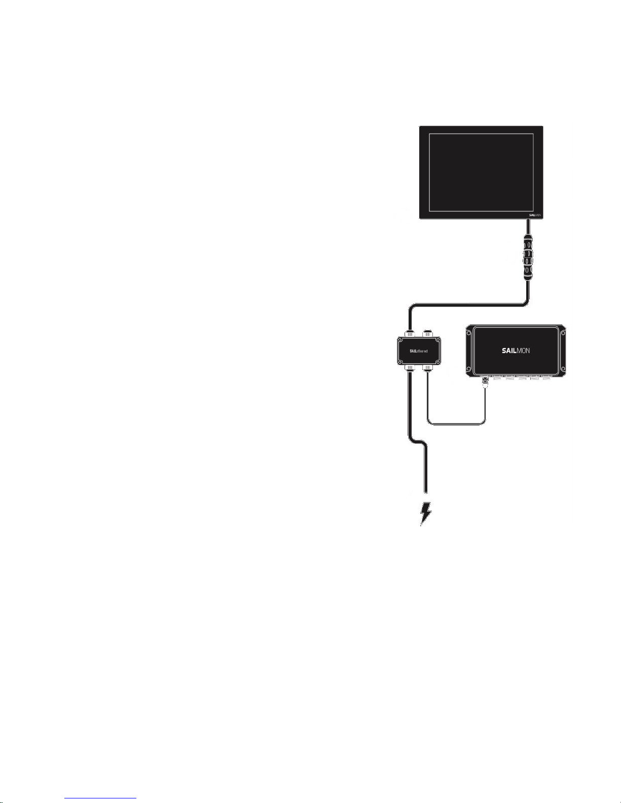
Standalone with Sailmon X7 or X10 display:
A Sailmon display can be connected using the SAILethernet and the ethernet port of the E4.
The USB wifi adapter is still used, with a PC or Tablet used to configure the displays though
navdesk.
Sailmon displays can easily be connected to each other using the daisy chain that is
provided, please note that:
- A maximum of two displays can be connected to a single 12V supply
- A maximum of four displays can be connected to a 24V single supply
Image 1.3
Example of standard Sailmon setup with display
SAILMON
Page 18

Requirements:
For setting up the architecture in image 1.3, the following is required
● Model E4 processor
● SailmonWindBox
● SAILethernet
● Ethernet cable
● NMEA 2000 GPS
● NMEA 2000 Speed depth TX (optional)
● TP - Link USB dongle
● Two extra NMEA 2000 pieces
More information about Sailmon displays can be found in chapter 3
Sailmon E4 processor and display upgrade / integration:
Image 1.3
Example of Sailmon E4 integration
SAILMON
Page 19

System Details:
● E4 integration into the boats new or existing system with the use of Sailmon Linear
Boxes, Sailmon Loadcell Boxes and NMEA 0183 multiplexer units.
● E4 ports 1 & 2 are configured and connected to different data protocols to enable
endless sensor configuration.
● A on board network is used to connect the E4 , displays and access point (4G unit
used to enable remote access) smart devices can again be used as extra displays.
● Again E4 and display configured and calibrated through a pc or tablet running nav
desk
1.4 E4 installation
Warning: Before starting the installation, make sure all electrical power is switched
off, the power supply is suited for the desired installation and the right cabling is
being used.
Make sure the E4 is mounted in a dry and well ventilated area., the E4 is not designed to be
watertight and should therefore not be in contact with water. Securely mount the E4 in the
desired location and mount with four screws.
The E4 has no orientation components so it is possible to mount the processor in any angle.
However, it is recommended to place the E4 with its connection ports downwards.
Connect data connections using image 1.2. Be sure to observe connector keyway alignment.
A bad connection will lead to data loss and the system under performing.
Ensure cables are suitably supported and are located where they will not become damaged
in any way. Consider cable protection in exposed cable runs.
SAILMON
Page 20

Recommended Fuse rating
Number of sailmon
displays
Supply Battery voltage
Fuse size
1 / 2
12V
6A
3 / 4
12V
12A
5 / 6
12V
16A
1 / 2
24V
6A
3 / 4
24V
10A
5 / 6
24V
12A
1.4.1 Network installation
It is vital for good communication that all network cables are of good quality and are being
used as designed . Ensure that all non sailmon products are in good condition and are fit for
purpose.
When connecting the E4 to a PC or tablet, several possibilities occur:
Ethernet:
Network cable: Simply connect the network cable into the ethernet port of the E4 and the PC
SAILMON
Page 21

Switch:
Sailmon displays are connected using the ethernet port of the E4. Because of this, there are
no more ports available to connect the PC to. A network switch is used to extend the number
of network ports in your system.
Wireless
TP - link: With the USB port of the E4, there can be a USB / Wifi stick connection. This way,
the E4 will create its own wireless network which can be detected by any wifi device
SAILMON
Page 22

4G Router
One of the benefits of a separate router is the possibility to insert a 4G SIM card so you are
able to connect to internet. Besides this, the wifi network can be used to view data on a
tablet or smartphone.
SAILMON
Page 23

1.4.2 Sailmon Network
Overview
Sailmon devices (the E4 Processor and all Screens) communicate using IPv4 over a
standard 100 MBit/s ethernet network. Using an S-Net box, or a direct ethernet connection to
the E4, it is possible to use standard networking equipment. Sailmon devices are designed to
work in any existing local area network, where they will acquire IP addresses from a DHCP
server and not interfere with other devices or services. Sailmon can be deployed as a
standalone as well, without a DHCP server on the network. In this case Zeroconf addressing
is used. The Model E4 processor can be configured to provide a DHCP server, or act as
simple Wifi access-point for convenience.
Sailmon applications (NavDesk, SailmonTool, Mobile Apps, etc.) are designed to be
connected to the same LAN as the devices and require no additional configuration.
Applications will automatically detect the presence of Sailmon products using two parallel
methods of discovery via UDP heartbeats and requests. The exact TCP and UDP port
numbers used by Sailmon are described in the next sections.
More complex LAN configurations, as well as external Wifi access-points, are possible given
they can fulfill the following requirements:
● At least 10 Mbps unicast bandwidth available between nodes
● At least 1 Mbps bandwidth for multicast or broadcast messages
● All given UDP and TCP ports must be open in both directions
● Additional ports are needed depending on the installation (see below)
● UDP multicast or broadcast packets must be able to reach every participant
Complex network installations
All Sailmon devices are required to share the same network. However, it is possible to run
Sailmon applications from a remote network, given they are connected by layer 2 (switches,
Wifi APs) or layer 3-4 (routers).
Unicast (point-to-point) communications generally work without issues over Wifi, and even
between multiple routed LANs or VLANs, which makes the initial discovery via UDP multicast
the most critical requirement. The network installation must ensure that packets to the
Sailmon multicast group “239.255.83.77” on ports 4019 and 4020 are not filtered and can
traverse to all desired devices. This means that switches may need to use “IGMP snooping”
option if the packets are filtered otherwise. When multiple networks / IP address ranges are
SAILMON
Page 24

present, a router must be configured to forward multicast packets to the neighboring
networks. Additional forwarding of UDP traffic may be required (see optional ports).
UDP Traffic
Ports required for Sailmon Apps
4019 Heartbeat requests
Applications send broadcast requests to this port. Sailmon Instruments will respond by
sending their heartbeat packet back to the source port on the requesting computer. This is a
fallback if clients are not able to join the multicast group, and used as a quick way to discover
devices on the network.
4020 Heartbeats
Source of heartbeat broadcasts sent every 2 seconds by Sailmon devices. Heartbeats are
required by every application to find the IP of the Sailmon server in an unknown network.
Heartbeats are broadcast and sent to the Sailmon multicast group. Join the multicast group
to receive them. They contain the serial number, software versions, etc. for each device.
4021 System configuration
Sailmon tool will send broadcast packets to all Instruments for global settings and server
management.
6130 Instrument commands
Receive port for commands to real or virtual Instruments. Used to trigger reload of
configuration and to show or hide the help screens during initial configuration.
6150 Data requests to Sailmon server
Used to request data values from the Sailmon data server. The client sends unicast UDP
packets containing desired IDs to the server at port 6150. The server responds to the source
host and port with the current values and status flags. When blocked, instruments will show
“no data”.
6152 Raw data output from server
Output port of live raw data values from all sensor
Ports required between Sailmon Devices
6000 Commands / requests for backlight control
Receive port for commands / requests to the backlight controller on each screen.The
backlight controller will respond to source host and port.
SAILMON
Page 25

4001 Button events send to Sailmon multicast group
4000 Sensor data sent to the server (NMEA 0183, SeaTalk, BandG, Nexus) (SBox
only)
4010 Source of NMEA 2000 data bridge over the SBox to the server (SBox only)
1001 Source of Fastnet data output to the SBox (SBox only)
URLs and IP addresses
Hardcoded IPv4 addresses
239.255.83.77 Sailmon Multicast Group (used instead of broadcasts)
192.168.4.1 E4 wired ethernet when DHCP server is enabled
192.168.5.1 E4 wireless interface when used as Access Point
SAILMON
Page 26

Chapter 2
2.1 Software
2.1.1 Software download
The Sailmon software can be downloaded from http://www.sailmon.com/support-2/
Here you will find:
● Latest software releases
● Release notes
● Older software versions
● Manuals
● FAQ
2.1.2 Minimum system requirements
● MAC OSX 10.10 or later
● PC Windows 7 or later
● IOS (Beta) IOS 10 or later
SAILMON
Page 27

2.2 Using software to connect to E4
You have now successfully installed the Sailmon model E4 Instrument system. If you
power up then the model E4 will automatically select available sensors. If there is more
than one sensor you need to select a sensor in Navdesk.
1. Download the Sailmon Apps from the App Store on your Smart device or from
http://www.sailmon.com/support-2/ for your PC.
2. Power the Sailmon instruments
3. Connect your computer or smart device directly to the E4, this can be done
using a ethernet cable, with a wifi stick or connect the E4 in to your existing boat
network.
4. Open the apps to show data or use your system
5. To add model E4 to your ships network disable the DHCP server and connect to
the desired network.
For detailed Navdesk info see the Sailmon software manual
SAILMON
Page 28

Chapter 3
3.1 Displays
3.1.1 product overview
Sailmon displays can be purchased in either Portrait or Landscape version. In both cases the
dimensions are the same. The difference is in the high end polarisation filter and software
settings. Casings are different shown by the Sailmon logo position.
When installing a display it will need to be connected to the ethernet port of the E4. The
SAILethernet is needed to combine both the data and power from the power supply and E4
to the display.
The displays can be connected in daisy chain, this means, only one cable is necessary from
your switching panel to the mast. Using Fast-lock waterproof connectors will reduce the
installation effort to a minimum. Sailmon displays includes the most powerful and intelligent
technology available, including automatic backlight control with an ultra-high dimming ratio of
1:3000.
This allows absolutely perfect readability under all conditions for convenient reading during
day and night. Even high contrast and intense colours are maintained during night sailing.
Perfect sunlight readability is achieved with a high-performance anti glare front screen. The
front glass is optically bonded to the TFT display, avoiding an air gap. Therefore, you will
never experience a foggy display. The displays are further optimized for ultimate visibility
with polarized sunglasses. Using polarized sunglasses will even improve the visibility of the
instrument.
Element VII Mounting Template
SAILMON
Page 29

SAILMON
Page 30

Element X Mounting Template
SAILMON
Page 31

3.1.2 Technical specifications
Element VII
● Display size: 800 x 480 Pixels
● Display type: LED - Backlit LCD
● Brightness: 1000cd/ m2
● Max brightness: min 0,3 / max 1000 nits
● Viewing angle: -85 + 85 degrees
● Maximum digit size: 9 cm
SAILMON
Page 32

Element X
● Display size:1024 x 768 pixels
● Display type: LED - Backlit LCD
● Brightness: 1000cd/ m2
● Max brightness: min 0,3 / max 1000 nits
● Viewing angle: -85 + 89 degrees
● Maximum digit size: 12 cm
SAILMON
Page 33

Power supply
12V system:
● Four 7’’ can be powered
● Two 10’’ can be powered
On a 24V system:
● Eight 7’’ can be powered
● Four 10’’ can be powered
SAILMON
Page 34

Chapter 4
4.1 Sailmon components
4.1.1 Snet connector
To connect displays to the Sailmon network or to each other, a Snet connector is used.
These connectors are suitable for use outside the hull due to the IP classification. This
classification is only effective when connectors are attached to each other. Loose connectors
can easily be damaged by moisture.
Snet cables can be purchased in two types:
● Ready - to - go: Customers have to know the exact length of the desired cable since
there will be a connector on both sides. Pulling the cable through the vessel will be
harder due to the large diameter
● Self build: On one side of the Snet cable, a female connector is already attached. The
male connector is provided to be mounted by the customer. Please note that for this,
a special crimp tool is needed, which can be purchased from Sailmon
Connectors should
never be forced together
due to the keyway in the
male connector. Gently
push the connectors into
each other and turn.
When turned correctly, a
small ‘click’ should be
heard. The connectors
are now locked.
Make sure you put the
waterproof dust-cap on
the last instrument to
prevent infiltration
SAILMON
Page 35

4.1.2 SAILethernet
This box has to be connected to the ethernet port of the E4 and the ship's power supply.
The SAILethernet powers and establishes a connection between your display and model E4
over ethernet.
This connection can be achieved by
adding both devices to an existing
network or connecting them directly
together.
The SAILethernet converts a regular
power cable and a regular cat-5 cable
into our proprietary 6 core S-NET
cable, which runs from the instruments
to the SAILethernet.
Figure 1.6
Cabling of SAILethernet
SAILMON
Page 36
4.1.3 Mounting
● Find a suitable location to mount the box
● Open the lid of the SAILethernet by unscrewing
the four screws.
● Mount the box with the power and ethernet
wires facing downwards.
● Pull the SNET cable from the Instrument
mounting location to the SAILethernet
mounting location. Leave the female connector
at the Instrument end.
● Pull a power cable from the power supply
location to the SAILethernet location.
● Pull a network Cable from the E4 (or network
switch) to the SAILethernet location.
● The SNET cable is supplied with the outside
stripped 70mm. This is the ideal length to
mount it in the SAILethernet, do not shorten
this.
● Unscrew the cable grommets and feed the
appropriate cable through the cable grommet.
● Strip wires and crimp ferrules.
● Insert the wires in the appropriate terminals.
When inserting the wires press the white push
button to enable insertion.
● Fasten the cable grommets with the outside
jacket 5mm inside the box (see figure 2)
● Repeat for each group of instruments
SAILMON
Page 37

4.1.4 Windbox
The Sailmon WindBox offers an interface for 3rd party wind sensors to the NMEA 2000 back
bone and in turn connection to the E4 processor..
The NMEA 2000 interface
cable is pre-installed. For
overvoltage and
electrostatic discharge
protection the WindBox is
galvanically isolated.
It will measure both wind
speed and angle at 100Hz.
It is housed in a waterproof
case rated to IP65
Technical specification Windbox
● Update rate: 100Hz for Sailmon, 10Hz for other instrument systems
● 5 m NMEA 2000 drop cable (pre-installed) (SeaTalk NG is available on request)
● Power Supply: 9-16V over NMEA 2000
● Dimensions (H x W x D): 98mm x 82mm x 33mm
● Weight: 160g (Cable: 240g) • Protection: IP65
● Ambient Temperature Range: -10°C to 50°C, 14°F to 122°F
● Power Consumption: 10mA at 12V
● Galvanic Isolation of MHU
● NMEA 2000 PGNs Supplied: 130306 (0x1FD02) with 10Hz, Sailmon proprietary
64231 (0xFAE7) for 100Hz MHU angle and speed
● Direct Raymarine ST70 calibration support
SAILMON
Page 38

Installation
Choose a dry and protected place for the Wind Box. The Wind Box is designed to be
installed inside the hull.
Do not install your Sailmon windbox on the head of the mast. This will make lighting
protection impossible and the NMEA 2000 specifications for the maximum drop cable
length are likely to be exceeded.
Feed the wind sensor cable into the left cable gland of the Wind Box and connect the wires
according to the color scheme printed on the circuit board
Operation
In case of sensor failure or incorrect connection, the blue status LED will blink 5 Times /
second.
If blue LED does not show up, check the NMEA 2000 power and network supply and
termination.
LED will be on in normal operation
SAILMON
Page 39

4.1.5 LinearBox
The Sailmon LinearBox is an interface for 3rd party linear sensors to be connected to
the E4 processor by means of the NMEA 2000 backbone. Up to 16 LinearBoxes can
be connected to a single E4 Processor. The linear box provides overvoltage and
electrostatic protection by means of galvanic isolation.
The E4 will measure linear inputs with an update rate of 4Hz allowing monitoring and
logging of all channels
Installation
This is a straightforward process.
The box is designed to be installed inside the hull. The preferred installation location is as
close to the sensor as possible. This will keep the analog wires between the sensor and the
LinearBox short. Please note that NMEA 2000 is designed so that you do not have to feed
analog wires across the boat, so keep sensor wires short and distribute your signals over the
NMEA 2000 bus.
After choosing a suitable installation
location, feed the sensor cable into the
left cable gland of the LinearBox and
connect the wires according to the
color scheme printed on the circuit
board.
SAILMON
Page 40

Technical specifications of the LinearBox
● Update rate: 4Hz
● 5m NMEA 2000 drop cable (pre-installed)
● Accuracy: 2% over Temperature
● Maximum input Voltage: 5000mV
● Minimum input Voltage: 0mV
● Measurement resolution: 10 bit, 1024 steps
● 5V Supply capability: 50mA for both channels (minimum sensor resistance 200 Ohms
on each channel)
● Dimensions (H x W x D): 98mm x 82mm x 33mm
● Weight: 160g (Cable: 240g)
● Protection: IP65
● Ambient Temperature Range: 0°C to 50°C, 32°F to 122°F
● Power Supply: NMEA 2000 compatible, 9-16V
● Galvanic Isolation of Linear Inputs to NMEA 2000, no isolation between channels
● NMEA 2000 PGNs Supplied: 64233 (0x0FAE9) Sailmon proprietary
SAILMON
Page 41

4.1.6 Loadcell Box
The Sailmon Loadcell Box offers connection of load cells to the Sailmon system. It can be
used to interface all common 4-wire or 6-wire load cells. Calibration is done with the Sailmon
Software Tool. For overvoltage and electrostatic discharge protection the Load Cell Box is
galvanically isolated.
It will measure tension or compression with an update rate of 4Hz, allowing monitoring and
logging of all loads. With the Sailmon System, the actual force can be displayed in N
(Newton), kg, or % of pin rated load
It is housed in a waterproof case and is rated to IP65
SAILMON
Page 42

Technical specification of Loadcell Box
● Update rate: 4Hz
● 5m NMEA 2000 drop cable (pre-installed)
● Accuracy: 1% over Temperature
● Maximum input Voltage: 39mV
● Minimum input Voltage: 0mV
● Dimensions: 98mm x 82mm x 33mm
● Weight: 160g (Cable: 240g)
● Protection: IP65
● Ambient Temperature Range: 0°C to 50°C, 32°F to 122°F
● Power Supply: NMEA 2000 compatible, 9-16V
● Isolation: Galvanic Isolation of Load Cell
● NMEA 2000: PGNs Supplied: 64221 (0x0FADD) Sailmon proprietary
SAILMON
Page 43

Chapter 5
5.1 system set ups
What are the minimum requirements of existing on board systems that Sailmon can work
with?
5.1.1 B&G
H3000
A H3000 CPU and fastnet network can
easily be Upgraded to an E4 processor
With the E4 it is possible to connect the
fastnet installation and retain the B&G
Displays.
A wind box will be needed and analog
transducers will need to be connected
with the use of a DST-2 to the E4 port 2
which is set to receive NMEA 0183.
.
SAILMON
Page 44

The Schematic below shows how the E4 can replace the H3000 CPU and still retain 20/20
displays and through hull transducers
Upgrade benefits:
- Reuse of existing transducers with use of an Actisense DST - 2
- Reuse of existing displays
- Wifi connectivity to stream data to any wifi enabled device
- Greatly improved calibration capabilities of existing sensors
- The ability to add Sailmon displays
For interfacing with fastnet displays, a GFD or FFD is still needed. Sailmon will receive and
send all data over the fastnet network but will be unable change display fields.
SAILMON
Page 45

H5000
Due to the H5000 use of the NMEA 2000 data format the E4 is a straightforward upgrade
from the B&G processor, resulting in greater usability and connectivity. All existing sensors
can be connected directly to the NMEA 2000 backbone or with the use of Sailmon interface
boxes.
Calibration and configuration is all completed using the Sailmon Navdesk tool
5.1.2 Garmin GNX displays
Due to the Garmin GNX displays use of NMEA 2000 data format they can be connected
directly to the NMEA 2000 backbone where the E4 processor can send data to the displays
as configured in the sailmon Navdesk
5.1.3 Raymarine
ST1:
Seatalk 1 is an older Raymarine protocol, The E4 processor is capable of converting this
data format via the Port I/0 connection. However, to be assured of a steady data flow we
recommend the use of a STng - St1 converter. With this device, Seatalk 1 is converted to
SeatalkNG and then connected to the NMEA 2000 backbone.
If this conversion is required, the following items have to be purchased:
Seatalk 1 - Seatalk NG converter.
this kit includes: converter, power cable, Stng drop cable, ST1 connection cable
Seatalkng to NMEA 2000 adapter
SAILMON
Page 46

Raymarine SeaTalk ng
Due to the SeaTalk NG’s use of the NMEA 2000 data format, the E4 is a simple upgrade,
gaining greater usability and connectivity. All exciting system sensors can be connected
directly to the NMEA 2000 backbone. Calibration and configuration is all completed through
the Sailmon Navdesk tool
Due to Raymarine custom connectors a STng - NMEA 2000 adapter cable will need to be
used.
5.1.4 Nexus
To upgrade an existing Nexus FXD instrument system a Garmin GND 10 will be needed to
convert the data to the NMEA 2000 protocol, this in turn can then be connected to the MNEA
2000 Backbone which is connected to the E4. Calibration and configuration is done through
the Sailmon Navdesk tool.
SAILMON
Page 47

5.2 Troubleshooting
5.2.1 NMEA 2000
In the event the system is up and running, but no data is visible on the displays check the
NMEA bus has correct power
The E4 does not power the NMEA 2000 backbone it will need a separate power connection
Please see the image below to have a clear view of a test setup.
For this setup to work, some backbone changes have to be made:
● Look for the terminator which is farthest away from the power supply.
● Place a T - piece between this terminator and the backbone, reconnect the terminator
to this junction.
● Connect the modified NMEA 2000 cable to the T-piece.
● Test voltage (red and black wires from NMEA 2000 cable)
A range between 11.5VDC and 14.4VDC is acceptable.
A higher voltage may indicate a possible malfunction of the vessels charging system.
A lower voltages may indicate the presence of faulty connectors or / and a voltage drop in
the vessel's power supply.
SAILMON
Page 48

5.2.2 NMEA 2000 details
● A drop cable,the cable that connects NMEA 2000 devices to the backbone
● Total of length of a drop cable longer than 6 meters (19.5 ft)
● On one NMEA 2000 backbone, there can be a maximum of 50 devices connected.
● The maximum current is 5 A
● The NMEA 2000 backbone is not meant to be extended, longer than 150 meters (490
ft)
● NMEA 2000 networking works exclusively with 12VDC.
SAILMON
Page 49

FAQ.
General
Q: My E4 is working but my displays say connecting to server.
A: Make sure both displays, controlling device and E4 are connected to the same DHCP
server.
Q: They are connected to the same DHCP server but displays still say connecting to
server.
A: Make sure the connections in the SAILethernet are correctly connected, if you have
installed a junction box somewhere, ensure this has also been connected correctly.
Q. How do I connect my depth and speed transducers?
A. If they are not NMEA 2000 but analog, we can supply a Actisense DST-2 to convert the
signal to NMEA 0183.
Q. Can I connect a B&G 213 or VMHU?
A. Yes our WindBox converts the signal to 100hz NMEA 2000 wind sensors
Q. Can I connect a load cell?
A. Yes our Loadcell Box is a load cell amplifier that can interface with most 4 or 6 wire
load cells and send the signal to NMEA 2000.
Q. Can I connect any other sensors?
A. Yes with our Linear Box you can input 2, 0-5V sensors to measure any value you
would like.
Q. Does your system interface with any navigation software?
A. Yes, we can speak with plotters over the NMEA 2000 bus, Expedition in the
expedition format over UDP and Adrena over ump using NMEA 0183.
Q. What if I want to display some custom sentences?
A. We have 128 channels available to send any data string over UDP you would like,
please contact us for the user guide!
Q. Anything you can’t do?
A. You tell us and we’ll try to implement it!
SAILMON
Page 50

Fastnet
Q: I have installed the E4, and connected the fastnet cable but there is no signal nor is
there a light.
A: Ensure it has been cabled and setup correctly this includes red and black.
Q: I have checked that the connection is right, but still no light, any ideas?
A: Make sure port 2 is set to B&G Fastnet in the Sailmontool.
Q: I have tried all of the above but still no light, any more ideas?
A: Disconnect the power from the fastnet bus, and measure the resistor between green and
white, it should be 50 Ohms. If it reads 70 Ohms there is just one resistor, if it reads 30 Ohms
there are 2.
Q: Great the light now comes on! But I don't receive any data if I look in Navdesk
diagnostics.
A: Since Model E4 can work with or without the B&G H2000 and H3000 processor, fastnet output
is disabled as default. Make sure to enable it.
Q: I still have a B&G processor in the network and the numbers are all over the place, any
idea?
A: Make sure the fastnet output is disabled, you can do this through Navdesk.
SAILMON
Page 51

No Network detected
Q: My E4 is working. On board is a Pepwave (or other kind of router) which is used as
a switch for the SAILethernet as well. I do not detect any network on smart devices.
A: Take the router out of the network. Then connect the SAILethernet to the E4 and check if
the displays work. If so, Sailmon works and the problem lies somewhere in the router.
SAILMON
Page 52

Windbox
Q: The blue status LED does not light up.
A: Check the NMEA 2000 power supply and the termination resistors of the NMEA 2000 bus.
Q: The blue status LED blinks 5 times per second.
A: Check the sensor connection and the sensor cable for errors. In case all connections are
working, the MHU sensor is most likely damaged.
Q: I cannot adjust the MHU offset with my instrument system (other than Sailmon)
A: The Wind Box is designed to be integrated into a Sailmon system. It does not provide
direct offset features since Sailmon uses advanced calibration which is done in other parts
of the system. Contact Sailmon support if you plan to use the Wind Box for other instrument
systems.
Q: My wind instrument (other than Sailmon) hangs or gets stuck.
A: Since the Wind Box delivers wind data with a high update rate of 100Hz, this may be too
much for some instruments. Special software is available in this case, to solve this problem
contact the Sailmon support team.
Q: After a software update, my Wind Box does not work anymore.
A: To solve this issue please get in contact with our support team.
SAILMON
Page 53
 Loading...