

Saia Burgess Controls PCD7.D412DTPF, PCD7.D412DT5F, PCD7.D457VT5F, PCD7.D410VT5F User Manual

Manual
I/O-modules
PCD7.D412DTPF standard SVGA MB Panel and
PCD7.D4xxxT5F programmable pWeb Panel
Document 27-620 | Release ENG07 | 2019-06-20
for PCD1 / PCD2 series
and for PCD3 series

Saia-Burgess Controls AG
0 Content
0 Content
0.1 Document versions ............................................................................... 0-4
0.3 Brands and trademarks ........................................................................ 0-4
1 Quickstart
1.1 Introduction ........................................................................................... 1-1
1.2 Denition of the connectors ................................................................... 1-1
1.3 Voltage supply of the panel ................................................................... 1-2
1.4 Dimensions and cut-out (in mm) ........................................................... 1-3
1.4.1 12.1" panel ............................................................................................ 1-3
1.4.2 10.4" panel ............................................................................................ 1-3
1.4.3 5.7" panel .............................................................................................. 1-3
1.5 Installation of the panels ....................................................................... 1-4
1.5.1 Installation in control cabinet ................................................................. 1-4
1.5.2 Drywall mounting set for MB panels ...................................................... 1-5
1.6 Operation and handling of the touchscreen .......................................... 1-5
1.7 Setting up communications for displaying a website ............................. 1-6
1.7.1 HTTP Direct over ethernet RJ-45 connector ......................................... 1-6
1.7.2 USB port as Service port ....................................................................... 1-7
1.7.3
Getting started with the Web Editor on the MicroBrowser panel PCD7.D4xx 1-7
Content
Content
0
2 Technical data for the two panel types
2.1 Technical data of the SVGA MicroBrowser panel .................................. 2-1
2.2 Technical data for the pWeb panels ...................................................... 2-2
2.2.1 Overview ............................................................................................... 2-2
2.2.2 Product-related presentation ................................................................. 2-2
2.2.2 Battery of the pWeb panel ..................................................................... 2-3
3 Logic controller of the programmable pWeb panel
3.1 Communications interfaces ................................................................... 3-4
3.1.1 On-board RS-485 .................................................................................. 3-4
3.1.2 Additional communications ports using slot A (Port no. 1) .................... 3-5
3.1.2.1 PCD7.F110S Serial Interface Module RS-485/RS-422 ........................ 3-7
3.1.2.2 PCD7.F121S Serial interface module RS-232
suitable for modem connection ............................................................. 3-8
3.1.2.3 PCD7.F150S Serial Interface Module RS-485 with Electrical Isolation 3-9
3.1.2.4 PCD7.F180S Serial Interface Module Belimo MP-Bus ........................ 3-10
3.2 Conguration of the hardware settings in PG5 ..................................... 3-11
3.2.1 General information ............................................................................... 3-11
3.2.2 Running the device congurator ........................................................... 3-12
3.3 Firmware version ................................................................................... 3-13
3.4 Downloading the program and backup ................................................. 3-14
3.4.1 Downloading the user program with PG5 ............................................. 3-14
3.4.2 Backing up and restoring the user program .......................................... 3-15
3.5 LED and operating status (12" pWeb panel, only) ................................ 3-16
3.6 Software Watchdog ............................................................................... 3-17
3.7 RIOs ...................................................................................................... 3-17
Manual PCD7.D412DTPF & PCD7.D4xxxT5F │ Document 27-620 – Release ENG07 │ 2019-06-20
0-1

Saia-Burgess Controls AG
4 Using the Setup menu
on the SVGA MB panels and pWeb panels
4.1 Opening the Setup menu ...................................................................... 4-1
4.2 Customising the start screen ................................................................. 4-2
4.3 Changing the password ........................................................................ 4-2
4.4 Saving and exiting ................................................................................. 4-3
5 Structure and description of the Setup menu
5.1 Network ................................................................................................. 5-2
5.1.1 DCHP On .............................................................................................. 5-2
5.1.2 TCP/IP address ..................................................................................... 5-2
5.1.3 Subnet Mask ......................................................................................... 5-2
5.1.4 Default Gateway .................................................................................... 5-2
5.1.5 Primary DNS Server .............................................................................. 5-2
5.1.6 Secondary DNS Server ......................................................................... 5-2
5.2 Logic Controller (pWeb panels, only) .................................................... 5-3
5.2.1 Program Name ...................................................................................... 5-3
5.2.2 Status: RUN or HALT ............................................................................ 5-3
5.2.3 S-BUS ................................................................................................... 5-3
5.3 Web Connection .................................................................................... 5-5
5.3.1 Connection ............................................................................................ 5-5
5.3.2 Type (no selection for pWeb) ................................................................ 5-5
5.3.3 Start page .............................................................................................. 5-5
5.3.4 Remote Host IP ..................................................................................... 5-5
5.3.5 Remote Port .......................................................................................... 5-5
5.3.6 Connection List ..................................................................................... 5-5
5.4 System .................................................................................................. 5-6
5.4.1 Production data ..................................................................................... 5-6
5.4.2 Info ........................................................................................................ 5-6
5.4.3 Settings ................................................................................................. 5-7
5.4.4 Special Settings .................................................................................... 5-8
5.4.5 Log ........................................................................................................ 5-8
5.4.6 Restart ................................................................................................... 5-8
5.5 Display .................................................................................................. 5-9
5.5.1 Brightness ............................................................................................. 5-9
5.5.2 Backlight [min] ....................................................................................... 5-9
5.5.3 Rotation ................................................................................................. 5-9
5.5.4 Calibrate Touchscreen ........................................................................... 5-9
5.6 Keyboard ............................................................................................... 5-9
5.6.1 SIP (Virtual Keyboard) ........................................................................... 5-9
5.6.2 Name of the rst keyboard .................................................................... 5-9
5.6.3 Width of the Focus (in Pixels) ............................................................... 5-9
5.7 Password .............................................................................................. 5-10
5.8 Language .............................................................................................. 5-10
Content
Content
0
Manual PCD7.D412DTPF & PCD7.D4xxxT5F │ Document 27-620 – Release ENG07 │ 2019-06-20
0-2

Saia-Burgess Controls AG
6 Localles/localserver
6.1 Connecting via FTP access ................................................................... 6-1
6.2 INTFLASH/WEBPAGES ........................................................................ 6-2
7 Updating and special settings
7.1 Firmware update ................................................................................... 7-1
7.1.1 Additional information on downloading FW ........................................... 7-1
7.1.2 Safe Firmware Download via USB ........................................................ 7-1
7.2 Reset / Resetting the device to factory settings .................................... 7-2
7.3 Backlight ................................................................................................ 7-2
7.4 Typefaces supported by MB panel PCD7.D4xx .................................... 7-3
7.5 Special Unicode fonts ........................................................................... 7-5
7.5.1 General information ............................................................................... 7-5
7.5.2 Multi-languages: Example ..................................................................... 7-7
7.5.3 Analysing incorrect fonts, font sizes or format templates ...................... 7-9
7.5.4 Web Editor ............................................................................................. 7-9
7.6 Internal special functions ....................................................................... 7-10
7.6.1 Container variable for SVGA MB panel ................................................. 7-10
7.6.2 uBT_BackLight Containerdiagramm ..................................................... 7-15
7.6.3 Additional uBTerminal container for "Save logs to File” function ........... 7-15
7.7 List of message box messages ............................................................. 7-16
Content
Content
0
8 Handling: precautionary measures
8.1 Glass touchscreen ................................................................................ 8-1
8.2 Information on the LCDs of the MB panel display ................................. 8-1
8.3 Care ...................................................................................................... 8-1
9 General recommendations for the Web Editor
9.1 In the "Project congurations" ............................................................... 9-1
9.2 In the Web Editor project (general information) ..................................... 9-1
9.3 Denition of an object in the Web Editor ............................................... 9-2
9.4 Handling ................................................................................................ 9-2
9.5 Some rules regarding gif images .......................................................... 9-2
9.5.1 Decompression in the video cache at startup using the Gif list ............. 9-3
9.5.2 Decompression of Gif les in the video cache at startup
using a dummy start screen .................................................................. 9-4
9.5.3 Decompression of Gif les: analysis/calculation ................................... 9-4
9.6 Expanded error messages for the SVGA panel .................................... 9-5
9.7 Extended alarm macros ........................................................................ 9-5
9.8 Trend macros for MB panels with "save logs to les" ........................... 9-5
A Appendix
A.1 Icons ...................................................................................................... A-1
A.2 Safety information ................................................................................. A-2
A.3 Waste of Electrical and Electronic Equipment (WEEE) disposal .......... A-3
A.4 Contact .................................................................................................. A-4
Manual PCD7.D412DTPF & PCD7.D4xxxT5F │ Document 27-620 – Release ENG07 │ 2019-06-20
0-3
Saia-Burgess Controls AG
Content
Document versions | Brands and trademarks
0.1 Documentversions
Version Published Redactor Remarks
EN01 2012-10-10 ErDa First version of manual
EN02 2012-11-28 HaMa
EN03 2013-12-18 ErDa Chapter 7.6.2 Container variables removed
EN04 2013-05-31 HaMa Chapter 3.1.2 Description oft the communica-
EN05 2014-01-20 HaMa New logo and new company name
ENG06 2016-01-27 HaMa New xation set
ENG07 2019-06-20 HaMa - Added the crossed bin logo for “Waste of
0
■ Ch1.2 Connection SD » D and /SD » D
■ Ch3.1.1 Picture RS-485-Network replaced
tion modules PCD7.F1xxS for Slot A
Electrical and Electronic Equipment (WEEE)”
disposal
- copied from Word to InDesign
0.3 Brands and trademarks
Saia PCD® and Saia PG5®
are registered trademarks of Saia-Burgess Controls AG.
Technical modications are based on the current state-of-the-art technology.
Saia-Burgess Controls AG, 2012. © All rights reserved.
Published in Switzerland
Manual PCD7.D412DTPF & PCD7.D4xxxT5F │ Document 27-620 – Release ENG07 │ 2019-06-20
0-4

Saia-Burgess Controls AG
1 Quickstart
Quickstart
Introduction | Denition of the connectors
1.1 Introduction
This manual covers the technical aspects of the PCD7.D412DTPF SVGA MB panel and the PCD7.D4xxxT5F programmable pWeb panel. The aim of the Quickstart
chapter is to facilitate the rapid installation of components of the PCD7.D4xxxT5F.
The following are discussed:
■ Denition of the connectors
■ Power supply and consumption
■ Dimensions
■ Possible communications modes
In other chapters, more details can be found about:
■ Hardware
■ Software (Setup menu step-by-step and conguration)
■ Usage, rmware update, etc.
■ Maintenance
Complementary manuals:
■ PG5 2.0 User guide | 26-732
■ File System and FTP Server | 26-855
■ Ethernet TCP/IP | 26-766
■ Smart RIO PCD3.T665 | 26-892
■ PCD3 series (conguration of the communications interfaces) | 26-789
1
1.2 Denitionoftheconnectors
PROTECTIVE EARTH MUST BE CONNECTED!
Manual PCD7.D412DTPF & PCD7.D4xxxT5F │ Document 27-620 – Release ENG07 │ 2019-06-20
1-1

Saia-Burgess Controls AG
Connections
Power Supply PCD7.F1xxS
Connector
pins
RS 485
Connector
pins
Signal
1 24 V (+)
2 GND (-)
Signal
1 GND
2 NC
3 /D
4 D
Quickstart
Denition of the connectors | Voltage supply of the panel
Connector
pins
0 GND GND
1 TXD232 SD
2 RXD232 /SD
3 RTS232
4 CTS232
5 GND GND
6 DTR232
7 DSR232
8 COM232
9 DCD232
Signal
RS 232
Signal
RS 485
1
Power supply
Communications
Reset button
Earth (-) / 24V (+) Connector, 2-pole
2× Ethernet (switch !) 2× RJ-45 with LED indicator
USB Standard USB slave
Pushbutton
1.3 Voltage supply of the panel
Pin Signal
1 24V (+)
2 Earth (-)
Current supply:
→ 24 VDC +30% / –20%
or
→ 19 VAC ±15% current supply with full-wave rectier
Current consumption Power output without back-
PCD7.D412DT5F
PCD7.D410VT5F
PCD7.D457VT5F
PCD7.D412DTPF Max 600 mA 5 W
Max 600 mA
Max 600 mA
max 500 mA
light
5 W
5 W
5 W
Current supply with jack plug for cable of max. 1.5 mm2.
Manual PCD7.D412DTPF & PCD7.D4xxxT5F │ Document 27-620 – Release ENG07 │ 2019-06-20
1-2

Saia-Burgess Controls AG
1.4 Dimensions and cut-out (in mm)
1.4.1 12.1" panel
62 6
Quickstart
Dimensions and cut-out (in mm)
1
Front panel W × H, 319 × 264
Display W × H, 245 × 185
1.4.2 10.4" panel
Front panel W × H, 281 × 221
Display W × H, 211 × 150
1.4.3 5.7" panel
Cut-out W × H, 300 × 244
62 6
Cut-out W × H, 262 × 202
50 6
Front panel W × H, 202 × 156
Display 5.7" W × H, 117 × 88
Manual PCD7.D412DTPF & PCD7.D4xxxT5F │ Document 27-620 – Release ENG07 │ 2019-06-20
Cut-out W × H, 189 × 142
1-3

Saia-Burgess Controls AG
1.5 Installation of the panels
1.5.1 Installation in control cabinet
■ The installation position is horizontal. Slide the unit into the installation cut-out.
■ Make sure that the ventilation slots are not covered, to allow air circulation and
the device does not overheat.
■ Install 4 mounting clamps for 5.7" (2 on top and 2 on the bottom), 6 clamps for
10.4" (2 on top, 2 on the bottom and 2 on the sides) and 8 clamps for the 12.1"
(3 on top, 3 on the bottom and 2 on the sides). Refer to the photos below.
Quickstart
Installation of the panels
1
Mounting parts of 12.1" panels
Mounting parts of 10.4" panels
Mounting parts of 5.7" panels
Note:
■ It is helpful to have somebody hold the unit from the front side of the panel
while the brackets are being installed.
■ The bolts require a 2.5 mm Allen key.
■ Screw the bolts into the brackets up to the point when you can still clip them
onto the MicroBrowser without being obstructed by the plate.
■ Clip them onto the unit then tighten the bolts until they touch the plate.
■ The required torque to seal the gasket is 20 cNm. To avoid breaking the clamp,
do not exceed 30 cNm.
How to ensure spray water protection according to IP65:
The device must be mounted on a at surface or wall. Tighten the bolts until the
front plate of the PCD7.D4xx is just touching the mounting surface/wall.
Manual PCD7.D412DTPF & PCD7.D4xxxT5F │ Document 27-620 – Release ENG07 │ 2019-06-20
1-4

Saia-Burgess Controls AG
1.5.2 Drywall mounting set for MB panels
The MicroBrowser panels are not just for mounting in the control cabinet; They
also look very good in the oce or living room, or mounted on a wall. This is why
we provide wall mounting kits for solid and cavity wall mounting.
Quickstart
Installation of the panels | Operation and handling
1
In-wall
Mounting kit for the 5.7” MB panel PCD7.D457-IWS2 PCD7.D457-OWS2
Mounting kit for the 10.4” MB panel PCD7.D410-IWS PCD7.D410-OWS
Mounting kit for the 12.1” MB panel PCD7.D412-IWS PCD7.D412-OWS
On-wall
In-wall(cavitywalls) On-wall (solid walls)
1.6 Operation and handling of the touchscreen
To operate the touchscreen, use only your nger, the stylus or a soft nger stylus.
Do not use sharp tools (e.g., sharp metallic objects, paperclips or a screwdriver,
etc.).
Manual PCD7.D412DTPF & PCD7.D4xxxT5F │ Document 27-620 – Release ENG07 │ 2019-06-20
1-5

Saia-Burgess Controls AG
Setting up communications for displaying a website
1.7 Setting up communications for displaying a website
1.7.1 HTTPDirectoverethernetRJ-45connector
The quickest communications port is the ethernet port via RJ-45, with the HTTP
Direct protocol selected. The speed is either 10 MBit/s or 100 MBit/s after an autonegotiation protocol with the connected device.
Internal connection for programmed pWeb panels
The programmed panels are connected internally directly to the programmable
logic controller, via an ethernet connection. It therefore suces, in this case, to
simply set the local host IP address 127.0.0.1 and HTTP Direct connection in the
Setup menu under Web connection. The programmable pWeb panels are obviously also capable of displaying websites from controllers located within the network.
The procedure for this is the same as with the standard 12” SVGA panel.
Connectingtoexternaldevices
If an ethernet connection to an Automation Server exists, the HTTP connection
can be established between our PCD7.D4xx and any SBC controller. In the case
of the programmable panels, the panel is generally connected to the internal con-
troller.
Quickstart
1
Ethernet http direct
Quick test of the SVGA panel
■ First the Saia PCD must have a web program loaded which was created with
the Web Editor (see 26-838_Manual_Web-Editor). You can ask the SBC Support Team for some examples. They will also soon be available on our website.
■ Using a CAT5 cable, you can connect our PCD7.D4xx terminal to the SBC
device. The current controllers support auto-crossing; a crossover cable is thus
no longer required.
■ Using PG5, dene the HW settings of the Saia PCD device: S-bus support
must be selected together with the TCP/IP channel where a valid IP address is
entered.
Manual PCD7.D412DTPF & PCD7.D4xxxT5F │ Document 27-620 – Release ENG07 │ 2019-06-20
1-6

Saia-Burgess Controls AG
Setup settings of the SVGA panel:
Congure the SVGA panel by opening the Setup menu (refer to chapter 5):
Quickstart
Setting up communications for displaying a website
Î First, be sure that you are on the same network subnet. For example, if the
Saia PCD has the IP address 192.168.12.92, give your terminal (in the Network
menu) an IP address like 192.168.12.90, as normally the subnet mask is set to
255.255.255.0.
Î In the Conguration menu, enter the Address of the start page that corre-
sponds to the IP address of the Saia PCD, and also enter its HTML start page
name.
Your MB panel should now be connected to the Saia PCD and the start page selection should be displayed on the screen. You can now navigate your web pages.
1.7.2 USBportasServiceport
The USB port on the programmable panels is used mainly to download the user
program onto the controller with PG5.
On SVGA standard MB panels, this port is generally used as a Service port. It is
used mainly to download new rmware programs onto the device.
The USB port meets the USB 1.1 specication. Maximum speed: 12 MBit/s.
1.7.3
Getting started with the Web Editor on the MicroBrowser panel PCD7.D4xx
1
Detailed documentation can be downloaded from our website. See manual 26-838
Manual Web Editor. To get started with programming the MB panel, some particular features must be observed:
■ If no assistance is available from the Wizard when creating a new project, the
project must be set up as follows:
● Using the virtual keyboard with SVGA MB panels
● See Chapter 5.6 Keyboard
● If you want to use the le Background.teq or foreground.teq, you rst need
to generate these les. Why is this? Before objects or text and elds can appear, these les must rst be positioned on each page.
● Once the project is ready to download, enter the desired HTML le name
and generate a Build Project. Then make a Webserver Build in the Saia PG5
Project Manager, so that all the les are held in the PCD. If you just want to
access the PCD with MB panel PCD7.D4xx and not with a PC browser, you
can reduce the amount of data by deleting the .jar les, as they are already
included on the panel.
Manual PCD7.D412DTPF & PCD7.D4xxxT5F │ Document 27-620 – Release ENG07 │ 2019-06-20
1-7

Saia-Burgess Controls AG
Technical data of the SVGA MicroBrowser panel
2 Technical data for the two panel types
The hardware of the SVGA MicroBrowser panels and the programmable pWeb
panels is dierentiated in several areas by the Programmable Logic Controller on
the pWeb panels. These are described in the following sections:
2.1 Technical data of the SVGA MicroBrowser panel
Display
Display size 12.1" TFT
Resolution SVGA 800 × 600
Backlight LED
Colours 65,536
Contrast adjustment Ye s
On Board File System 128 MByte
Operating system
Internetservices
Interfaces
Ethernet 10 / 100 M 2× RJ45 (switch)
Current consumption
Voltage supply
Protection class (front)
Temperature
Relativehumidity
Processor
Real Time Clock (RTC)
Saia PCD COSinuS with SBC MicroBrowser expansion
Automation Server, SBC MicroBrowser
Max 600 mA
24 VDC±20 %
IP65
Operation: 0 … 50°C
Storage: –25 … +70°C
Operation: 10 … 80%
Storage: 10 … 98% (non-condensing)
Coldre CF5373L, 240 MHz
Yes, with Supercap
Technical data
2
Manual PCD7.D412DTPF & PCD7.D4xxxT5F │ Document 27-620 – Release ENG07 │ 2019-06-20
2-1
Saia-Burgess Controls AG
Technical data of the SVGA MicroBrowser panel
2.2 Technical data for the pWeb panels
2.2.1 Overview
Logic controller
User program, ROM /DB/text 1 MByte
RAM/DB/text 1 Mbyte
Media 14,336 ags / 16,384 registers
Backup for user User program is saved to the integrated micro SD card
File system for user 128 MBytes, on-board
Program cycle time 10 cycles / sec maximum
Protocolsoneldlevel
Internetservices
Interfaces
Ethernet 10 / 100 M 2× RJ45 (switch)
USB (1.1 / 2.0) 1× client
Serial interfaces RS-485 & socket for PCD7.F1xxS communications module
Temperature range
Relativehumidity
Processor
Real Time Clock (RTC)
Battery
Serial-S-bus, Ether-S-bus, Ether-S-I/O, Modbus RTU,
TCP or M-bus
SBC MicroBrowser, Automation Server
Operation: 0 … 50°C
Storage: –25 … +70°C
Operation: 10 … 80%
Storage: 10 … 98% (non-condensing)
Coldre CF5373L, 240 MHz
Yes, with battery back-up
Lithium Renata CR 2032 (lifetime 1-3 years)
Technical data
2
2.2.2 Product-related presentation
Technical data PCD7.D457VT5F PCD7.D410VT5F PCD7.D412DT5F
Display size 5.7 TFT 10.4 TFT 12.1 TFT
Resolution/Pixels VGA 640 × 480 SVGA 800 × 600
Touchscreen Resistive four-wire Resistive ve-wire
Contrast adjustment yes
Backlight LED
Voltage supply 18 - 32V
Current consumption Max. 500 mA Max. 600 mA
Protection class (front) IP 65
Front status LED No No Yes
Manual PCD7.D412DTPF & PCD7.D4xxxT5F │ Document 27-620 – Release ENG07 │ 2019-06-20
2-2

Saia-Burgess Controls AG
2.2.2 Battery of the pWeb panel
The hardware components are maintenance-free, with the exception of the CPUs
for the pWeb panel, whose battery requires occasional replacement.
Technical data
Technical data of the SVGA MicroBrowser panel
The components do not contain any user-replaceable parts. If hardware problems
occur, please return the components to Saia-Burgess Controls.
The resources (register, ags, timer, counters, etc.) and the character strings/DBs
are stored in the RAM. In order to prevent these from being lost, and to enable
the hardware clock to carry on running during a power failure, the devices are
equipped with a back-up battery:
CPU model Buer Buertime
PCD7.D4xxx Renata CR 2032 lithium battery 1-3 years
1)
Depending on the ambient temperature: The higher the temperature, the shorter the buer time.
1)
New controllers include batteries in the scope of delivery, and these must be
inserted during commissioning. Pay attention to the polarity of the batteries.
CPUs with lithium batteries are not maintenance-free. The battery voltage is monitored by the CPU. The status LED lights up (12” pWeb panel only) and XOB 2 is
called if:
■ the battery voltage is lower than 2.4 V;
■ the battery is missing.
2
In order to avoid data-loss, we recommend changing the batteries while the panel
is connected to the power supply.
■ Disconnect from the voltage supply.
■ Remove the cover of the pWeb panel.
■ To prevent data loss while changing the battery 119B, reconnect to the voltage
supply.
■ Push the terminal holder back slightly (see arrow in gure).
■ Remove the battery.
■ Insert a Renata CR 2032 button battery so that the positive terminal is in con-
tact with the terminal holder.
■ Disconnect from the voltage supply and reattach the back wall of the panel.
Manual PCD7.D412DTPF & PCD7.D4xxxT5F │ Document 27-620 – Release ENG07 │ 2019-06-20
2-3

Saia-Burgess Controls AG
Communications interfaces
3 Logic controller of the programmable pWeb panel
3.1 Communications interfaces
Various communications interfaces are integrated into the programmable logic
controller. These can also be expanded by installing an additional module.
Logic Controller
3.1.1 On-board RS-485
PCD4.DxxxT5F PCD3.Mxxxx PCD2.M5xxx PCD1.M2xxx
GND
/D
D
The pin nos of the connected PCD are explained in the respective manual.
Make sure that the terminators are properly terminated.
In the example below, you can see a possible connection between the terminals
and PCDs. In order to avoid reection on the communications channel, the network should be terminated with termination resistors. The PCD7.D4xx has a switch
for this:
3
RS-485-Network
Pull up
330 Ohm
Termination
Resistor
150 Ohm
Pull down
330 Ohm
First station Middle stations
PCD1.M2_
Port #1
+5 V
/n
n n
PCD1.M2_
PCD2.M5_
n n
Bus RS485
Segment length max. 1200 m
PCD3.Mxxxx
max. 32 stations
End station
PCD7.D457VT5F
PCD7.D410VT5F
PCD7.D412DT5F
+5 V
/n/n
/RX - /TX
RX - TX
/n
Manual PCD7.D412DTPF & PCD7.D4xxxT5F │ Document 27-620 – Release ENG07 │ 2019-06-20
3-4

Saia-Burgess Controls AG
Thefollowinggureshowsyouwhereitislocated.
Î If the switch is in the top position, the network is closed.
Î If the switch is in the bottom position, the network is open.
Conguration can either be performed directly, via the Setup menu on the pWeb
panel, or indirectly, via the Hardware conguration on the PG5. Overwrite the
current conguration the same as when making a change.
Logic Controller
Communications interfaces
3
3.1.2 Additional communications ports using slot A (Port no. 1)
Slot A on the pWeb panels allows you to plug in optional modules for communications interfaces. Only modules of the PCD7.F1xxS series are supported.
Installation - PCD7-D412DT5F
Earth 2 × Ethernet
(switch)
USB Reset
Switch
PCD7.F1xxS RS-485 Power Supply
Multi-colored front LED
Manual PCD7.D412DTPF & PCD7.D4xxxT5F │ Document 27-620 – Release ENG07 │ 2019-06-20
3-5

Saia-Burgess Controls AG
Installation - PCD7.D410VT5F
Logic Controller
Communications interfaces
Earth 2 × Ethernet
(switch)
Installation - PCD7.D457VT5F
Earth 2 × Ethernet
(switch)
USB Reset
Switch
USB Reset
Switch
PCD7.F1xxS RS-485 Power Supply
3
PCD7.F1xxS RS-485 Power Supply
Connections
PCD7.F1xxS
Connector
pins
0 GND GND
1 TXD D
2 RXD /D
3 RTS
4 CTS
5 GND GND
6 DTR
7 DSR
8 COM
9 DCD
Signal
RS-232
Signal
RS-485
RS-485
Connector
pins
1 GND
2 NC
3 /D
4 D
Power Supply
Connector
pins
1 24 V (+)
2 GND (-)
Signal
Signal
Manual PCD7.D412DTPF & PCD7.D4xxxT5F │ Document 27-620 – Release ENG07 │ 2019-06-20
3-6

Saia-Burgess Controls AG
3.1.2.1 PCD7.F110S Serial Interface Module RS-485/RS-422
Termination resistors can be connected (CLOSED) or disconnected (OPEN) with
slide switchs.
PCD7.F110S RS-485 terminator
Slider
O
C
21
Open not terminated
(factory setting)
Logic Controller
Communications interfaces
3
Slider
O
C
21
Closed terminated
RS-422 connection
Port x.1 - 10 pin spring-loaded terminal block
RS-422
0 PGND Tx 1
2 /Tx Rx 3
4 /Rx PGND 5
6 RTS /RTS 7
8 CTS /CTS 9
Terminal
Pin
PGND 10
TX 11
/TX 12
RX 13
/RX 14
PGND 15
RTS 16
/RTS 17
CTS 18
/CTS 19
RS-422
Peripherie-
device
PGND
TX
/TX
RX
/RX
SGND
RTS
/RTS
CTS
/CTS
RS 485 connection (Electrically connected RS-485 interface)
Port x.1 - 10 pin spring-loaded terminal block
RS-485
0 PGND Rx-Tx 1
2 /Rx-/Tx 3
4 PGND 5
6 7
8 (SGD) 9
PCD Modul
RX - TX
/RX - /TX
Terminal
x0
x1
x2
RS-485
GND
RS-485
RS-485
Peripherie-
device
PGNDPGND
RX - TX
/RX - /TX
For more details, see Manual 26-740, section "Installation components for RS-485
Networks."
Manual PCD7.D412DTPF & PCD7.D4xxxT5F │ Document 27-620 – Release ENG07 │ 2019-06-20
3-7

Saia-Burgess Controls AG
3.1.2.2 PCD7.F121S Serial interface module RS-232 suitable for modem connection
PCD7.F121S
RS-232 connection
Port x.1
RS-485
0 PGND TxD 1
2 RxD RTS 3
4 CTS PGND 5
6 DTR DSR 7
8 COM DCD 9
10 pin spring-loaded terminal block
Logic Controller
Communications interfaces
3
RS-232 connection to DTE RS-232 connection to DCE
cable
External modem
(ETCD) DCE
PGND
TX
RX
RTS
CTS
SGND
DTR
DSR
DCD
0 PGND
1 TXD
2 RXD
3 RTS
4 CTS
5 PGND
6 DTR
7 DSR
8 Reserve
9 DCD
cable
Peripherie
device (DTE)
PGND
TX
RX
RTS
CTS
SGND
DTR
DSR
DCD
0 PGND
1 TXD
2 RXD
3 RTS
4 CTS
5 PGND
6 DTR
7 DSR
8 Reserve
9 DCD
Manual PCD7.D412DTPF & PCD7.D4xxxT5F │ Document 27-620 – Release ENG07 │ 2019-06-20
3-8
Saia-Burgess Controls AG
Communications interfaces
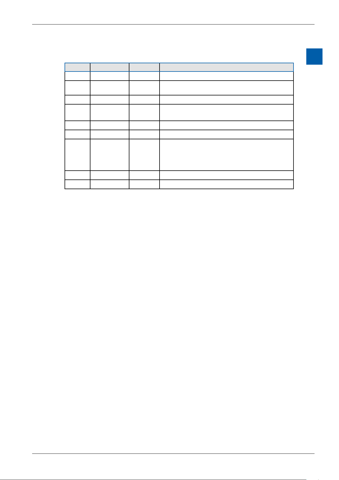
3.1.2.3 PCD7.F150S Serial Interface Module RS-485 with Electrical Isolation
Electrical isolation is achieved with three optocouplers and a DC/DC converter.
Data signals are protected against overvoltage with an anti-surge diode (10 V).
Electrical isolation is achieved using three optical couplers and a DC/DC converter.
The data signals are protected against excess voltages by a suppressor diode
(10 V).
The line terminator for port x.1 is integrated into the module and can be activated
using the silde switch on the module.
PCD7.F150S RS-485 terminator
ON
C
O
1 2
ON
C
O
1 2
Closed terminated
Slider
Open not terminated
(factory setting)
Logic Controller
3
Slider
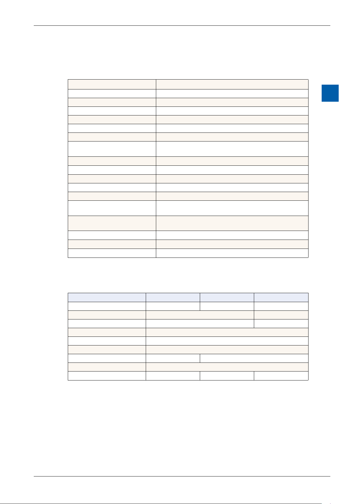
RS 485 connection - 10 pin spring-loaded terminal block
Port x.1
RS-485
0 PGND Rx-Tx 1
2 /Rx-/Tx 3
4 PGND 5
6 7
8 (SGD) 9
PCD Modul
RX - TX
/RX - /TX
Terminal
x0
x1
x2
RS-485
GND
RS-485
RS-485
Peripherie-
device
PGNDPGND
RX - TX
/RX - /TX
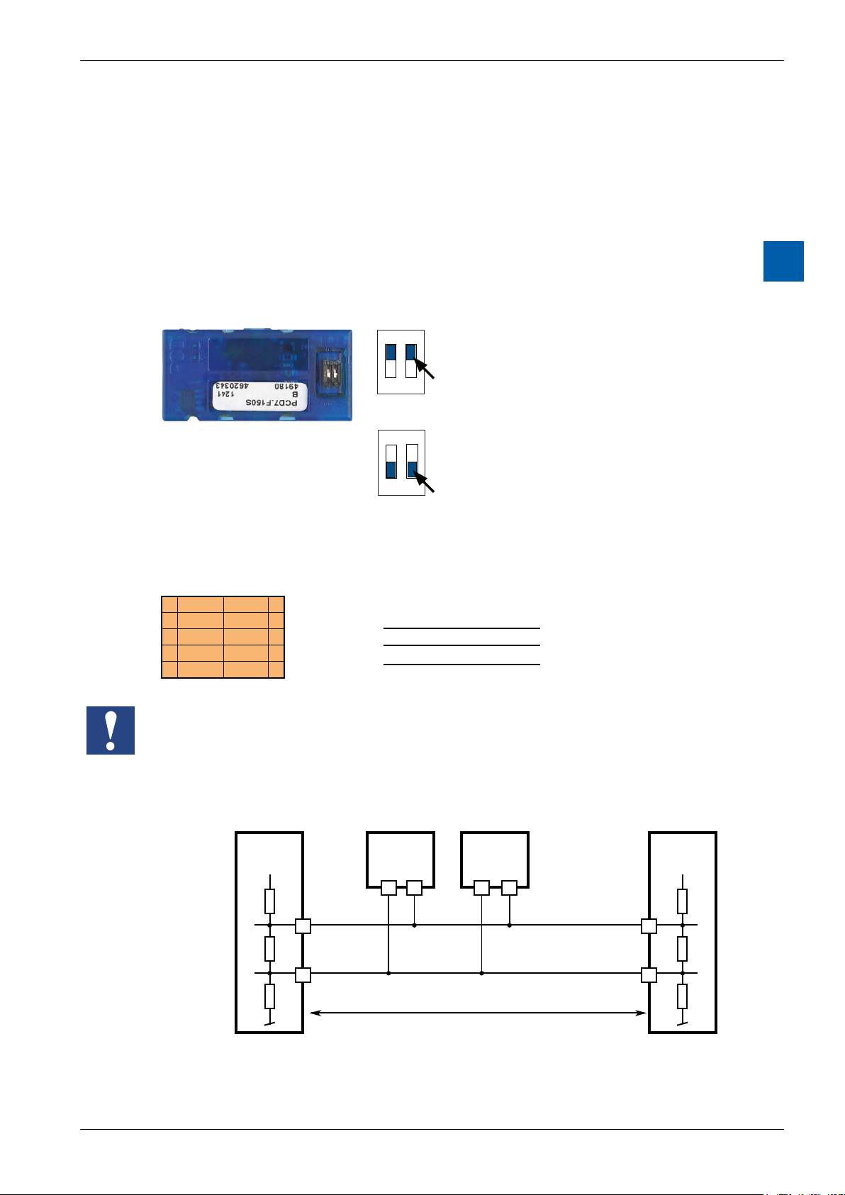
When using this module, the permitted ambient temperature for the control unit is
reduced by 5°C.
Line terminator:
First station Middle stations End station
+5 V
/n
Pull up
330 Ohm
Termination
Resistor
150 Ohm
Pull down
330 Ohm
+5 V
n n
28
Bus RS-485
29 n
Segment length max. 1200 m
max. 32 stations
/n/n
/RX - /TX
RX - TX
More details are available in the manual 26-740 “Installation components for
RS-485 networks”.
Manual PCD7.D412DTPF & PCD7.D4xxxT5F │ Document 27-620 – Release ENG07 │ 2019-06-20
3-9

Saia-Burgess Controls AG
3.1.2.4 PCD7.F180S Serial Interface Module Belimo MP-Bus
Up to 8 actuators and sensors can be connected.
PCD7.F180S
Belimo connection
Port x.1
Belimo MP-Bus
0 PGND MP 1
2 ‘MFT’ ‘IN’ 3
4 PGND 5
6 7
8 (SGD) 9
10 pin spring-loaded terminal block
Logic Controller
Communications interfaces
3
MP-Bus cabling
0 PGND Earth connection, MP line
1 MP Multi-point
The MP-Bus is the Belimo master slave
bus. Up to 8 slaves can be connected to
a master device.
These are:
■ MFT(2) ap drives
■ MFT(2) valve drives
■ MFT re damper drives
■ VAV NMV-D2M compact controller
2 ‘MFT’ MFT programming unit (internal MP-Bus)
3 ‘IN’ detection of MFT programming unit
(input 10 kΩ, Z5V1)
5 PGND Earth connection, MFT programming unit
Manual PCD7.D412DTPF & PCD7.D4xxxT5F │ Document 27-620 – Release ENG07 │ 2019-06-20
3-10

Saia-Burgess Controls AG
Conguration of the hardware settings in PG5
3.2 CongurationofthehardwaresettingsinPG5
Conguration of the programmable panel is usually performed via PG5, which is
also used to generate the project. However, it can also be congured directly on
the panel, using the Setup menu described in Chapter 5.2.
3.2.1 General information
Logic Controller
The following description assumes that the user is familiar with the PG5 software.
If this is not the case, we recommend reading the manual 26/733 „PG5, software
requirements, PG5 V 2.0" The device congurator denes direct access to programming instructions, for reading values from the peripheral input module and
writing values to the peripheral output module.
3
Manual PCD7.D412DTPF & PCD7.D4xxxT5F │ Document 27-620 – Release ENG07 │ 2019-06-20
3-11

Saia-Burgess Controls AG
3.2.2 Runningthedevicecongurator
The device congurator is used for hardware conguration, setting up logs, and
I/O handling.
Double click on the project tree icon to start the device congurator.
Logic Controller
Conguration of the hardware settings in PG5
3
Use a right click to select the Device and use Change Device Type to set the panel
to be congured.
The Download button can be used to download the conguration onto the pWeb
Panel.
Manual PCD7.D412DTPF & PCD7.D4xxxT5F │ Document 27-620 – Release ENG07 │ 2019-06-20
3-12

Saia-Burgess Controls AG
3.3 Firmwareversion
The rmware of the programmable panel is stored on an SD card soldered to the
motherboard. A rmware update can be applied by downloading a new version
with the PG5. When doing so, pay attention to the following procedure:
● Open www.sbc-support.com and download the latest rmware version
● Establish a connection between PG5 and the CPU, the same way as when
downloading an application (in accordance with the available devices, serial
with PGU cable, modem1), USB, Ethernet).
● In the Tools menu, select "Update Firmware” and use the Browse function to
select the path for the le with the new rmware version. Make sure that only
one le is selected for download.
● Start the download.
1)
see chapter “"3.1.2.2 PCD7.F121S Serial interface module RS-232
suitable for modem connection" on page 3-8”
Logic Controller
Firmware version
3
Manual PCD7.D412DTPF & PCD7.D4xxxT5F │ Document 27-620 – Release ENG07 │ 2019-06-20
3-13

Saia-Burgess Controls AG
3.4 Downloading the program and backup
The user program is downloaded to the pWeb panel in the same way as performing device conguration with the PG5 software. This process is described below.
3.4.1 Downloading the user program with PG5
Logic Controller
Downloading the program and backup
1 Create and compile the user program
The le your_project.pcd contains the following information:
User program (FUPLA, IL, etc.)
Conguration les (in some cases)
Data for rst initialisation
2 Program download
Clicking on the Download button shows the
following window.
The user program is downloaded as a le in
a particular partition of the internal le system. The user is not able to see this partition.
4 Options after download
Execute program
(RUN)
Remain STOPPED After the download,
Sets the PLC to RUN,
once the download is
successfully completed
PLC remains
STOPPED
3
■ It is not possible to download only those blocks which have been modied.
■ The user program is downloaded into the on-board memory in a le and, after
a restart of the system, the process is complete.
■ If the download is not successfully completed, the FW deletes all les inside
the system folder.
Once the download has been successfully completed, start the controller:
After the system restart, the user program and ROM DB/text are transferred into
the execution memory. This is a write-protected memory and thus does not need
to be backed up; all data is stored in the pWeb panel le system.
The data for the user program is transferred to the execution memory after the
pWeb panel device starts up.
Manual PCD7.D412DTPF & PCD7.D4xxxT5F │ Document 27-620 – Release ENG07 │ 2019-06-20
3-14

Saia-Burgess Controls AG
3.4.2 Backing up and restoring the user program
Backup with PG5
Select a backup with "Backup To Flash”
Logic Controller
Downloading the program and backup
3
Since the user program is already stored in the on-board ash memory, only the
RAM DB/text for the on-board ash memory are stored to the folder PLC_SYS (not
visible to the user).
Note: Registers, ags, timers and counters are not stored.
During a restore, the DB/text are copied back into the SRAM memory.
BackuptoINTFLASHlesystem
The values RAM DB/text are stored in the internal PCD_Backup folder. This allows
the backup les to be accessed via the FTP server and then uploaded to a PC.
Manual PCD7.D412DTPF & PCD7.D4xxxT5F │ Document 27-620 – Release ENG07 │ 2019-06-20
3-15

Saia-Burgess Controls AG
LED and operating status (12" pWeb panel, only)
3.5 LED and operating status (12" pWeb panel, only)
The CPU is capable of the operating statuses listed in the following table. On the
12" pWeb panel, the status is indicated by a multicoloured LED. On the other panels, the status can be shown on the display.
Status Description LED
No power No power connected aus
Run Normal processing of the user program
after startup
Run (conditional) Conditional Run status A condition has
been set in the debugger (Run until...),
which has not yet been fullled
Run with error The same as Run, but with an error mes-
sage
Run (conditional) with
error
Stop The status Stop occurs in the following
Stop with error The same as Stop, but with an error mes-
Halt The status Halt occurs in the following
The same as Run (conditional), but with an
error message
cases:
■ Downloading with the option “Remain in
Stop status”
■ PGU stopped by programming unit
sage
cases:
■ Halt instruction processed;
■ Serious error in the user program;
■ Hardware fault;
■ No program loaded;
■ No communications mode on the S-Bus
PGU or Gateway Master Port.
System diagnostics Description LED
Battery fault in Run Flashes at interval of 500 ms orange green orange green
Battery fault in Run
conditional
Battery fault in stop /
halt
No SD memory card red blue green red blue green
SD memory card but
no rmware
green
green…green…green
green
green…green…green
red
red
red
red green red green
red…red…red
red green blue red green blue
Logic Controller
3
Manual PCD7.D412DTPF & PCD7.D4xxxT5F │ Document 27-620 – Release ENG07 │ 2019-06-20
3-16

Saia-Burgess Controls AG
3.6 Software Watchdog
The pWeb panels have a Software Watchdog, which is a self-monitoring function
of the pro-cessor which restarts the CPU in the event of a malfunction or loop. The
core of the Software Watchdog is the instruction SYSER K 1000. The rst time this
is output, the Watchdog function is activated. This instruction must then be output at least every 200 ms, otherwise the Watchdog is triggered and the controller
restarted.
Instruction:
SYSWR K 1000 ; Software Watchdog instruction
R/K x ; Parameters according to following table
; K constant or entered value Register
Logic Controller
Software Watchdog | RIOs
3
x = 0
x = 1
x = 2
XOB 0 calls are entered in the PCD History as follows:
«XOB0WDOGSTART» if XOB0 was triggered by the Software Watchdog
«XOB0STARTEXEC» if XOB0 was triggered by a supply fault
3.7 RIOs
Smart-RIO PCD3.T66x modules can be used for decentralised expansion via ethernet (see also manual 26-892):
The Software Watchdog is deactivated
The Software Watchdog is activated; if the instruction is not repeated within 200 ms,
a cold start is performed.
The Software Watchdog is activated; if the instruction is not repeated within 200 ms,
XOB 0 is called, then a cold start is performed.
Manual PCD7.D412DTPF & PCD7.D4xxxT5F │ Document 27-620 – Release ENG07 │ 2019-06-20
3-17

Saia-Burgess Controls AG
4 Using the Setup menu
on the SVGA MB panels and pWeb panels
This chapter describes the menu structure of the SVGA MicroBrowser panel and
programmable pWeb panel.
MicroBrowser SVGA panel
● PCD7.D (12.1” SVGA)
Using the Setup menu
Opening the Setup menu
ProgrammablepWebpanels(rmware1.19.34):
● PCD7.D412DT5F (12.1” SVGA)
● PCD7.D410VT5F (10.4” VGA)
● PCD7.D457VT5F (5.7” VGA)
4.1 Opening the Setup menu
4
To call up the Setup menu:
Î Touch any area on the screen (except the buttons) for 4 seconds at any time
Î Touch the icon displayed during startup (see section 5. TITLE
Î The SETUP menu also contains an ONLINE help function (touch the Help icon)
Manual PCD7.D412DTPF & PCD7.D4xxxT5F │ Document 27-620 – Release ENG07 │ 2019-06-20
4-1

Saia-Burgess Controls AG
4.2 Customising the start screen
The title screen is displayed for a few seconds, immediately after the panel is
switched on with ON. The greeting and welcome screen can be dened under
System Start screen (see “5.4.3 Settings” on page 5-7)
Using the Setup menu
Customising the start screen | Changing the password
4
Available for a few seconds only,
pressing on this icon will take you
directly to the Setup menu.
= Animated icon for “Please wait, data loading”
User-dened System Start screen: “5.4.3 Settings” on page 5-7
4.3 Changing the password
MB panels of the PCD7.D4xxxx series are supplied without a password on the
Setup menu.
If, however, access to the Setup menu is subsequently restricted with a password,
the correct password must be entered, and then conrmed with OK.
→ For information on entering passwords, see “5.7 Password” on page 5-10
Manual PCD7.D412DTPF & PCD7.D4xxxT5F │ Document 27-620 – Release ENG07 │ 2019-06-20
4-2

Saia-Burgess Controls AG
4.4 Savingandexiting
Using the Setup menu
Saving and exiting
4
If you have changed one or more parameters, you must conrm if you want to
save the changes, to save & reboot, or to reset the new parameters without sav-
ing.
Manual PCD7.D412DTPF & PCD7.D4xxxT5F │ Document 27-620 – Release ENG07 │ 2019-06-20
4-3

Saia-Burgess Controls AG
Structure and description of the Setup menu
5 Structure and description of the Setup menu
The Setup screen is the rst screen which is displayed when the Setup menu is
accessed.
5
Network MB panel settings See section 5.1
1
Logic Controller Congure the internal logic controller
2
(pWeb panels, only)
Web Connection Congure the web connection See section 5.3
3
System Info/Settings/Special Settings/FW download &
4
Reboot
Display Display settings See section 5.5
5
Keyboard Virtual keyboard See section 5.6
6
Password Enter a password See section 5.7
7
Language Selection of the language (E, G, F, I and Dutch) See section 5.8
8
Back to application Back to application
9
See section 5.2
See section 5.4
Manual PCD7.D412DTPF & PCD7.D4xxxT5F │ Document 27-620 – Release ENG07 │ 2019-06-20
5-1

Saia-Burgess Controls AG
5.1 Network
This is where you can congure the network settings for the panel. Depending
on the network, the connection may also work without setting a gateway or DNS
server. You can exit the menu using the Setup button.
On pWeb panels, the network conguration is generally performed using the PG5 device congurator. If the Device Conguration is updated via PG5, the data set in Setup is overwritten. If you
want this data to be carried over to the PG5, the conguration requires the conguration le to be
uploaded into the PG5 project.
5.1.1 DCHP On
If DCHP is o, an IP must be set by the user. Otherwise all the necessary settings
are acquired by the DCHP server.
Structure and description of the Setup menu
Network
5
5.1.2 TCP/IP address
IP address of the panel.
5.1.3 Subnet Mask
Subnet mask of the network on which the panel is located.
5.1.4 Default Gateway
IP of the standard gateway.
5.1.5 PrimaryDNSServer
IP of the primary DNS server.
5.1.6 SecondaryDNSServer
IP of the secondary DNS server.
Manual PCD7.D412DTPF & PCD7.D4xxxT5F │ Document 27-620 – Release ENG07 │ 2019-06-20
5-2

Saia-Burgess Controls AG
5.2 Logic Controller (pWeb panels, only)
Settings of the programmable logic controller in pWeb panels. The settings congured here can also be made in the PG5 Device congurator.
If the Device Conguration is updated via PG5, the data set in Setup is overwritten. If you want this
data to be carried over to the PG5, the conguration requires the conguration le to be uploaded
into the PG5 project.
5.2.1 Program Name
Displays the name of the loaded PG5 project.
Structure and description of the Setup menu
Logic Controller (pWeb panels, only)
5
5.2.2 Status: RUN or HALT
Displays the status of the logic controller.
5.2.3 S-BUS
Conguration of the S-bus of the internal logic controller.
Î S-Bus Station
S-bus station of the logic controller
Î Serial
Settings for the serial S-bus connection
● Active
Activates the serial connection
● PGU
When PGU is activated, the panel can be programmed via the serial inter-
face
● Port
For setting the S-bus port
● Mode
Data or parity
● Baud reate
Speed of the S-bus
● TS Delay
Sets a transmission delay. Setting 0 causes the default values to be used
● TN Delay
Sets a transmission delay. Setting 0 causes the default values to be used
Manual PCD7.D412DTPF & PCD7.D4xxxT5F │ Document 27-620 – Release ENG07 │ 2019-06-20
5-3

Saia-Burgess Controls AG
Î Serial Master Gateway
Settings for the master gateways
● Active
Activates or deactivates the master gateway
● Port
Port of the master gateways
● Mode
Data or parity mode
● Baud rate
Sets the baud speed of the serial S-bus
● Start address
First S-Bus station on gateway
● End address
Last S-Bus station on gateway
● Speed
Speed of connection
Î IP
For setting the IP address
● Active
Activates S-bus via IP
● PGU
If PGU is activated, the panel can be programmed via this interface.
● Port
Port of the IP connection
Î IP Master Gateway
● Active
For setting the master gateway
● Timeout
Timeout for a expected response which should be received (Standard 0)
● Start address
First S-Bus station on gateway
● End address
Last S-Bus station on gateway
Structure and description of the Setup menu
Logic Controller (pWeb panels, only)
5
Manual PCD7.D412DTPF & PCD7.D4xxxT5F │ Document 27-620 – Release ENG07 │ 2019-06-20
5-4

Saia-Burgess Controls AG
5.3 Web Connection
This is where you can set the data for the device from which the website is to be
loaded and displayed. On programmable pWeb panels, this is usually the internal
controller, and so the Local Host IP Address 127.0.0.1 must be set.
Structure and description of the Setup menu
Web Connection
5.3.1 Connection
Name of the connection.
5.3.2 Type (no selection for pWeb)
Local Only for SVGA MB panel
No connection with any PCD
Connection is made with the local IP address 127.0.0.1
HTTP Direct Direct connection (Ethernet, only)
5.3.3 Start page
Name of the start page for this connection.
5.3.4 Remote Host IP
IP address of the connected PCD.
5.3.5 Remote Port
5
Remote port (default: 80).
5.3.6 Connection List
We advise you to establish one or more connections (up to x16) from the “List of
Connections”. Edit the connection or connections and select the connection which
you would like to use for your project. Each connection can be edited at any time.
The names for the connections are required as the URL jump target in the Web
Editor:
Examples: the connection in the list is called conn2_http, and the start page of the
project Start.html
Manual PCD7.D412DTPF & PCD7.D4xxxT5F │ Document 27-620 – Release ENG07 │ 2019-06-20
5-5

Saia-Burgess Controls AG
5.4 System
5.4.1 Production data
Display of the most important production data, such as serial number and ASN.
Î ASN
SBC product number (order number)
Î Serial number
Serial number of the device
Î MAC Address
MAC address of the device
Î HW Version
Hardware version of the device
Î Production Date
Month in which the device was produced
Î Display Type
Type of display (internal designation)
Î HW LCD Rotation
Rotation of the display
Structure and description of the Setup menu
System
5
5.4.2 Info
System info, such as Firmware Version, Booter Version, etc.
Î Firmware Version
Î Booter Version
Î M1 Expansion Info
Î Video Cache Permanent
Î Erasable Video Cache
Firmware version currently installed on the panel
Booter version currently installed on the panel
Indicates if an M1 memory expansion is present (or a F1xxS module on the
pWeb panel)
Info: permanent video cache used
Info: cache is used for images. Dependent upon the size and number of gif les
in the cache
Manual PCD7.D412DTPF & PCD7.D4xxxT5F │ Document 27-620 – Release ENG07 │ 2019-06-20
5-6

Saia-Burgess Controls AG
5.4.3 Settings
General settings for the panel.
Î Buzzer
Buzzer which sounds when buttons are operated or certain actions are performed
● BuzzerOn/O
Buzzer signal when buttons are operated On / O
● Buzzer frequency
Pitch of the buzzer
Î File Search Order
Local / remote les
● Nolocallesearch
“No local le search” means les (teq, .gif, etc.) are not searched for on the
local server of the MB panel.
● Local before remote
“Local before remote” means les (.teq,.gif, etc.) are searched for rst on the
local server, before the PCD server is searched. Files are searched for rst
in INTFLASH/Webpages
● Remote before local
“Remote before local” means le (.teq,.gif, etc.) are searched for on the re-
mote server, before the local server on the MB panel is searched.
Î Start Delay [s]
Start delay for restart (min. 1 sec., max. 15 sec.)
Î Start screen
Enter the greeting & modify the welcome screen
● Startup text
Freely-denable greeting (max. 64 characters)
● X-position of the text
Value between 0 and 639
● Y-position of the text
Value between 0 and 479
● Nameofthegraphicle
gif graphic le: INTFLASH/WEBPAGES/…
● X-position of the graphic
Value between 0 and 639
● Y-position of the graphic
Value between 0 and 479
Î FileCacheActive
During normal operation, the le cache should be active.
The le cache can be activated and deactivated. Deactivation is used, for ex-
ample during project handling, because changes to cached les are trackable.
Î Setup Call With Delay
Activates or deactivates the delay.
Structure and description of the Setup menu
System
5
Manual PCD7.D412DTPF & PCD7.D4xxxT5F │ Document 27-620 – Release ENG07 │ 2019-06-20
5-7

Saia-Burgess Controls AG
5.4.4 Special Settings
Special system settings.
Î Reset All Parameters
This command resets all parameters to the default values.
Î FormatIntash
Extended function with request for conrmation: “Do you really want to format
INFLASH?” This command wipes the ash memory and recreates the le system from scratch. After the Formatting OK message, the device returns to the
System menu.
Î Time
Real Time Clock (RTC)
● Time
Real Time Clock (RTC): enter time (container: uBT_RtcTime)
● Date
RTC: enter date (container: uBT_RtcDate)
● TimeServerActive
Activates/deactivates the time server
Î Memory
Only in problem cases!
Outside of the permissible memory range Heap 1, 2, 3 and LR.
Î Show Runtime Info
Extended command on the run time
Structure and description of the Setup menu
System
5
5.4.5 Log
Clicking the button scrolls further through the list. This allows you to check, for
example, if typefaces are found. The last screen gives info on error messages.
Access to log.txt via FTP: uBT_FS/LOG.TXT
5.4.6 Restart
Restarts the system.
Manual PCD7.D412DTPF & PCD7.D4xxxT5F │ Document 27-620 – Release ENG07 │ 2019-06-20
5-8

Saia-Burgess Controls AG
5.5 Display
5.5.1 Brightness
Can be adjusted in a range between 0 and 20.
5.5.2 Backlight [min]
Structure and description of the Setup menu
Display | Keyboard
The touchscreen or buttons are not selected during this period, the backlight is
switched o. You can activate it again by touching the screen or a button. Can be
adjusted in a range between 0 and 5000.
5.5.3 Rotation
Landscape / Portrait
5.5.4 Calibrate Touchscreen
Carefully, using the stylus
5.6 Keyboard
5.6.1 SIP (Virtual Keyboard)
5
Activates/deactivates SIP (Soft Input Panel).
Virtual Keyboard
5.6.2 Nameoftherstkeyboard
You can choose from: Alphapad.teq (alphanumeric) or keypad.teq (numeric) as the
rst keyboard to open.
5.6.3 Width of the Focus (in Pixels)
You can select a value from 0 to 6 pixels. A frame identies the selected area or
edit eld. The entry denes the frame width in pixels. At a width of 0, no frame is
displayed. This is advisable if you are working only with the touchscreen.
Manual PCD7.D412DTPF & PCD7.D4xxxT5F │ Document 27-620 – Release ENG07 │ 2019-06-20
5-9

Saia-Burgess Controls AG
5.7 Password
You can enter an alphabetic, numeric or alphanumeric password (maximum number of characters = 32, incl. spaces). You must conrm the password after entering
it.
When you enter a new password, you have to conrm it. If the characters entered
in the conrmation eld do not match the new password, the old password is re-
tained.
If you would like to disable password protection, press the Enter key and conrm
without inputting any characters.
Forgot your password? Delete the le inash/cong/passwd.dat (FTP connection). This will
resolve your problem.
Structure and description of the Setup menu
Password | Language
5
5.8 Language
You can select one of the precongured languages for the Setup process.
Manual PCD7.D412DTPF & PCD7.D4xxxT5F │ Document 27-620 – Release ENG07 │ 2019-06-20
5-10

Saia-Burgess Controls AG
6 Localles/localserver
6.1 ConnectingviaFTPaccess
The internal structure can be accessed only via FTP: SBC le system (FTP access: user name and password). ftp:// IP address
FILE CACHE: Contains the cache memory
INTFLASH: Contains:
● INTFLASH/CONFIG/
KEYMAP.DAT Congure keyboard - only MB with buttons (F-keys).
Does not apply to this MB panel.
PASSWD.DAT Only displayed if a password has been creased (Forgot your
password? Delete this le.)
TSPOINTS.DAT For internal use
● INTFLASH/WEBPAGES Directory for all project les which you want to save
"LOCALLY” (teq,gifles,etc.)
● INFLASH/FONT FONT directory must be created by the user. It contains all
the special or additional .bft les containing typefaces.
● INFLASH/TRENDLOGS TRENDLOGS directory is created automatically
when logs are stored. The .CSV les with the logs are saved to this location
automatically (this uses Web Editor MB Macro S2F).
● PLC_SYS Internal use, no access (conguration sett., uBT_containers, etc.)
● BUBT_FS UBT_FS/LOG.TXT List of the startup process + Error info (read,
only)
● WEB For internal use.
● SLOFLASH Created automatically when an SD memory card is use with the
SD card interface.
Local les / local server
Connecting via FTP access
6
Manual PCD7.D412DTPF & PCD7.D4xxxT5F │ Document 27-620 – Release ENG07 │ 2019-06-20
6-1

Saia-Burgess Controls AG
xxxxxxxxxxx.TEQ
xxxxxx.ITQ
6.2 INTFLASH/WEBPAGES
Caution:thedirectoryname"M1_Flash”usedintheSBClesystemonthe
current QVGA and VGA MB panel no longer exists on this panel. The direc-
torynameoftherootlevelis"INTFLASH”
xxxxxxx.TEQ
xxxxxxxx.GIF
Local les / local server
INTFLASH/WEBPAGES
6
1) Recommended simplest method: Copy all shared les (.teq, .gif, etc.) to INTFLASH/WEBPAGES.
N.B.: If you have copy .teq or .gif les (or even .itq, .csv and .html les) when using a local server,
then you must always create at least one .tcr with all the PPO data (Web Builder).
Caution: Switch the Setup option from "No local le search" to "Local le search
before remote"!
2) Copy all associated les (.teq + .gif ) to the corresponding subdirectories of INTFLASH/WEBPAGES/. Each associated station has its own subdirectory. The names of the subdirectories correspond to the communication method:
HTTP direct communication IP address of the station with an underscore instead of a dot
e.g. IP address 192.168.12.90 becomes 192_168_12_90)
Copy les to INTFLASH/WEBPAGES/192_168_12_90
xxxxxxxxxxx.TEQ
xxxxxxxxxx.GIF
xxxxxxxx.HTML
Manual PCD7.D412DTPF & PCD7.D4xxxT5F │ Document 27-620 – Release ENG07 │ 2019-06-20
!!! File names: max. 24 ASCII characters without spaces, including le extension.
N.B.: If you have copy .teq or .gif les (or even .itq, .csv and .html les) when using a
local server, then you must always create at least one .tcr (Web Builder), as it
contains all the PPO data. Do not forget to switch the Setup option from "No local
le search" to "Local le search before remote”.
6-2

Saia-Burgess Controls AG
7 Updating and special settings
7.1 Firmware update
7.1.1 Additional information on downloading FW
If problems occur while downloading via a USB connection, try the following
solution:
Restart the MB panel with the USB cable REMOVED. Press the Download button
and the MB panel’s Download mode is activated. Next, connect the USB cable to
the MB panel and press Start in the FW Download Service Program.
If problems occur while downloading via a USB or ethernet connection, try the
following solution:
Updating and special settings
Firmware update
If communications are interrupted during the download process, no notication
appears on screen. This is because the FW ash memory is erased at the start of
the process.
7.1.2 SafeFirmwareDownloadviaUSB
The safe method for downloading rmware is always via USB.
a) Switch o the MB panel
b) At the top of the back cover os a hole of 3 mm in diameter. It contains a button.
Take a narrow-tipped pen or a small screwdriver (any cylindrical object with a
diameter of 3 mm is suitable) and use it to hold down the button for short while.
You can see the location of the Reset button in the gure:
7
c) Switch on the MB panel with ON at the same time. Wait 3-4 sec. until the LED
starts to ash.
Then download the FW using the SBC FW Service Program.
CAUTION: The *.blk le type is used for a complete FW le. Use only those
les intended for the PCD7.D4xx panel and which were supplied
by Saia Burgess Controls.
Manual PCD7.D412DTPF & PCD7.D4xxxT5F │ Document 27-620 – Release ENG07 │ 2019-06-20
7-1

Saia-Burgess Controls AG
7.2 Reset/Resettingthedevicetofactorysettings
In a number of particular cases, the Reset button can be used to fully reset the MB
panel and restore the factory default settings.
When could this function be of use?
If, for example, you have copied the local le required for an FTP connection
with the local server into the wrong directory or have unintentionally deleted data
which is necessary for displaying the Setup menu. The most common error is
the appearance of the message "uBTerminal not found”, while the content on
screen remains unchanged. In such a case, proceed as follows:
1) A. Switch o the MB panel with OFF
2) Activate the Reset button, at the top of the device’s rear cover, by holding down
the button.
3) Switch on the MB panel at the same time. After approx. 5 sec., the buzzer is
activated with increasing frequency.
4) Once the pitch (or the frequency) of the buzzer has stabilised (after approx.
10 sec.), release the Reset button and wait.
5) You may have to wait to 1 to 2 minutes. During this time, the FW is reconstructing the whole organisation of the memory and recreating all the les which are
required for the default settings. Finally, the MB panel reboots automatically,
and you will be asked to recalibrate the touchscreen. Once you have calibrated
it, the system has been fully restored.
Updating and special settings
Reset / Resetting | Backlight
7
7.3 Backlight
The period for which the backlight remains on can be set manually. This function
helps to save energy. If the backlight is deactivated, you will save approx. 3/4
watts, which is a non-negligible value. This will also extend the servicelife of the
backlight.
Servicelifeofthebacklight
The normal service life of the backlight (at 25°C) is dened as approx. 50 Kh. This
corresponds to 5 years of continuous use. However, this value is quickly reduced
(to half or less) if the operating temperature is 10°C or less. It makes sense for
the user to take this into account and to adapt the standby period of the backlight
accordingly.
Manual PCD7.D412DTPF & PCD7.D4xxxT5F │ Document 27-620 – Release ENG07 │ 2019-06-20
7-2

Saia-Burgess Controls AG
Typefaces supported by MB panel PCD7.D4xx
7.4 Typefaces supported by MB panel PCD7.D4xx
Default fonts available for the VGA MB panel
FONT SIZE
Fonts and formats 10 12 14 16 20 24 36
Arial × × × × × ×
Arial Bold × × × ×
Courier New × × ×
Courier New Bold × ×
Tahoma × × × ×
Tahoma Bold × × ×
Calculatingthegivenamountofplayfor:
Single text eld, multi-line text eld, edit eld for text eld, and button with text.
Updating and special settings
7
Denitions:
Font size: Character size (font size in pixels)
Y-dimension: Size of the graphical symbol (in pixels)
X-dimension: Width of a character
Text length: Length of a single-line piece of text.
Text eld: Length of the painter
General recommendations for textelds (you can nd info in the online help for
the rst version of Web Editor)
We recommend using text elds exceeding the size displayed in the Editor by up
to 20%. To determine the text eld length, you can also consult the following table
of the min. and max. X-dimension.
General recommendations for the Y-dimension in proportion to the font size and
format
Basic rule: The text should be INSIDE the contours.
For buttons and edit elds, a shadow of 2 pixels is added (to the inside of the
button contours and to the outside of the edit elds).
If the text is too large for the edit eld, it is overlaid by the border and the 3D
shadow.
Manual PCD7.D412DTPF & PCD7.D4xxxT5F │ Document 27-620 – Release ENG07 │ 2019-06-20
7-3

Saia-Burgess Controls AG
Updating and special settings
Typefaces supported by MB panel PCD7.D4xx
The following borders must be planned for:
● Single text elds and such with multiple lines: 2 × border width + 1
● Buttons: 2 × border width + 5
● Edit elds 2 × border width + 5
Font size y Size min x Size max x Size
Arial 36 41 7 36
Arial 24 28 7 24
Arial 20 23 6 20
Arial 16 19 3 16
Arial 12 15 3 12
Arial 10 12 3 10
Arial Bold 36 41 9 35
Arial Bold 24 28 7 23
Arial Bold 20 23 6 20
Arial Bold 14 16 4 15
CourierNew 20 23 12 12
CourierNew 16 19 10 10
CourierNew 12 14 7 7
CourierNew 10 12 6 6
CourierNew Bold 20 23 12 12
CourierNew Bold 14 17 8 8
Tahoma 24 29 5 24
Tahoma 20 25 4 20
Tahoma 16 20 4 16
Tahoma 12 15 4 12
Tahoma 10 13 3 10
Tahoma Bold 24 29 7 29
Tahoma Bold 20 25 6 24
Tahoma B
old 14 17 4 17
7
Manual PCD7.D412DTPF & PCD7.D4xxxT5F │ Document 27-620 – Release ENG07 │ 2019-06-20
7-4

Saia-Burgess Controls AG
7.5 Special Unicode fonts
7.5.1 General information
The user can add additional fonts, for example, which are required for some
languages or special fonts/formats/sizes, which are not provided for by default on
the MB panel.
Such languages include: Russian, Greek, Chinese, Japanese, Korean.
Such fonts include: Comic sans MS, Charleworth, Book Antica, Century,
Trebuchet, Verdana.
Dierent sizes, such as 10,12,14, etc., or formats such as plain (or normal), bold,
etc., can be used on all these fonts.
Updating and special settings
Special Unicode fonts
Fonts and Unicode fonts: http://www.sbc-support.ch Product Info
HMI Web-Panel PCD7.D4xxx Additional information for Sales Companies
(restricted Area).
Files containing typefaces for specic languages or fonts/formats/sizes not
appearing in the list can also be installed on an MB panel. If you want to do so,
please contact SBC Support.
To ensure that all characters are supported, we recommended using the Arial
typeface. This is particularly the case for languages with a large number of
characters, such as Chinese.
This means using Unicode les with typefaces (.bft) generated and made available
by Saia Burgess Controls. The rmware searches the following locations for
typefaces:
INTFLASH/FONT
A le with typefaces contains the data for a continuous string of characters. If, for
example, Greek and Cyrillic are required, two les must be loaded: one with the
Greek alphabet and another containing the Cyrillic characters.
The size of such a font le must not exceed 128 KBytes.
7
(Chinese requires many les with dierent font sizes to cover all the characters.)
Manual PCD7.D412DTPF & PCD7.D4xxxT5F │ Document 27-620 – Release ENG07 │ 2019-06-20
7-5

Saia-Burgess Controls AG
If a font le is found, it is registered. A maximum of 65 dierent les can be
registered. When a character is required, the front le is opened and the data for
the characters is called up. The data is intended for subsequent use.
Updating and special settings
Special Unicode fonts
Î Name of the font les: max. 24 ASCII characters without spaces (including le
extension)
Î To install font les: copy the les to the FTP server of the MB panel via an FTP
connection.
Î Chinese fonts: 12 is the smallest legible font size.
7
Manual PCD7.D412DTPF & PCD7.D4xxxT5F │ Document 27-620 – Release ENG07 │ 2019-06-20
7-6

Saia-Burgess Controls AG
7.5.2 Multi-languages: Example
Î Switch to a dierent language with the button (set the variable with the mouse
button held down).
Examples: Translate "Happy Birthday" to Czech using the "HTML TAG” type.
The Czech requires an expansion of the European characters, which can be
downloaded by logging into the SBC Support site.
Procedure:
● The Unicode font .bft le(s) with expanded European character set must be
copied into INTFLASH /FONT (see section 13.1).
● Web Editor: create the static text "Happy Birthday” and select "HTML TAG” as
the source type.
● Under the "Text Positions Advanced” tab for position settings: if you are using
exotic characters (such as Katakana, Chinese, etc.), we recommend sticking
with the default settings for the text position (not centred or justied).
● In some typefaces, it is not possible to represent all Unicode characters. We
recommend using the "Arial Unicode MS" or "MS Sans Serif" typefaces, as they
are well suited to use with Unicode characters.
Updating and special settings
Special Unicode fonts
7
DonotedittheCSVleintheS-WebEditordirectly, because the text window
of the S-Web Editor will save the CSV le in ASCII mode. You could, for example,
use Notepad to edit your CSV les (or another text editor, which allows you to
save the les in Unicode format). In the Notepad "Save As" dialog box, you can
select the "Unicode” entry in the dropdown menu under "Encoding". In MS Excel,
use the format "Unicode Text”.
Once you have saved your CSV les in the Unicode format and selected a
typeface in the HMI which can be used to display Unicode characters, then the
Unicode strings should be displayed properly. If you want to use Unicode, you do
not need to make any further settings in the S-Web Editor.
Manual PCD7.D412DTPF & PCD7.D4xxxT5F │ Document 27-620 – Release ENG07 │ 2019-06-20
7-7

Saia-Burgess Controls AG
Web Editor: Create a button with the following action parameters "Actions Set Variables":
The type is the "Container”, the name is "@LANGUAGE” and then the Unicode
.csv le.
Updating and special settings
Special Unicode fonts
7
We recommend copying the .csv les into the local server of the MicroBrowser
panel, under INTFLASH/ Webpages/…
Î For information on the topic of multilingual displays, see also "Multilingual HMIs”
in the online help of the Web Editor.
Manual PCD7.D412DTPF & PCD7.D4xxxT5F │ Document 27-620 – Release ENG07 │ 2019-06-20
7-8

Saia-Burgess Controls AG
Updating and special settings
7.5.3 Analysing incorrect fonts, font sizes or format templates
1 Arial, same format, keep size
2 Arial, simple, keep size
If the size is not available for Arial:
3 Same typeface, same format, reduce size to next possible size
4 Same typeface, simple, reduce size to next possible size
If there is no smaller typeset for this typeface:
5 Arial, same format, reduce size to next possible size
6 Arial, simple, reduce size to next possible size
If there is no smaller typeset for Arial:
7 Arial, same format or simple, usethesmallestavailablefontsize
If you replace a typeset, then this is logged in the log le.
Special Unicode fonts
7
7.5.4 Web Editor
Unicode character sets are available:
● using the source type "HTML TAG” in the Web Editor and with a .CSV le.
● by entering the text directly into the Web Editor as a string. In this case, no
.CSV les are necessary. Do not import any Web Editor projects created using Microsoft Windows using Unicode Character Set A into any other Windows
project created using Unicode Character Set B.
Manual PCD7.D412DTPF & PCD7.D4xxxT5F │ Document 27-620 – Release ENG07 │ 2019-06-20
7-9

Saia-Burgess Controls AG
Updating and special settings
Internal special functions
7
Description
(based on 125,250,500,1000,2000,4000,8000)
Set before using the alarm.
A change in frequency while the alarm is sounding will take eect only
when the next alarm is called.
Dene a value to start or stop the pulsed, acoustic alarm.
The acoustic alarm can be started by setting an interval time
(0 - 30,000 mSec) for the pulsed signal.
A 50% pulse/pause ratio is used, i.e. the pulse time is equal to the pause
time.
Changes made while the alarm is already sounding are ignored.
At a setting of 0, however, the alarm is immediately deactivated.
MaxvalueMax
length
Min length
Type Default Minvalue
Decimal value string 1000 125 8000 Frequency setting for the acoustic alarm (Hz)
sec.
The alarm is stopped immediately by touching the screen.
As pulse width modulation is used, this setting has an eect on the per-
ceived pitch of the alarm.
Set before using the alarm!
A change in volume while the alarm is sounding will take eect only when
the next alarm is called.
SIP keyboard: AutoRepeat on (1), o (0 )
switched OFF if the value was previously ‘1’. When the screen is touched,
the backlight is switched back on again immediately.
Read/Write 0, 1 à Remote control for backlight ON. The backlight is
switched ON if the value was previously ‘0’. There may be a delay when
switching o.
Remote control via PPO <-> Container coupling, only.
Use on painters for buttons and edit elds is not supported.
Container
(source HN 10.03.10)
quency
Congle
entry
The conguration le UBTERMINAL.TXT is not accessible via the FTP connection, because this le is located in the (write-
protected) subdirectory / PLC_SYS/CONFIG/.
Containers allow the application to exchange data with the rmware. All container variables havethe prex "uBT_". Pay attention to
upper/lower case!!!
7.6 Internal special functions
7.6.1 ContainervariableforSVGAMBpanel
Manual PCD7.D412DTPF & PCD7.D4xxxT5F │ Document 27-620 – Release ENG07 │ 2019-06-20
R/W uBT_AlarmFre-
No uBT_AlarmStart Decimal value string 0 0 30000 = 30
R/W uBT_AlarmVolume Decimal value string 10 0 20: 100% Volume of the acoustic alarm (0 - 20).
R/W uBT_AutoRepeat Boolean value string 0 0 1 Via the Soft Input Panel SIP (on-screen keyboard), use:
No uBT_BackLight Boolean value string 1 0 1 Read/Write 1, 0 à Remote control for backlight OFF. The backlight is
7-10

Saia-Burgess Controls AG
Updating and special settings
Internal special functions
7
Description
On, 0 : O).
MaxvalueMax
length
Min length
Type Default Minvalue
Status of the backlight is set to read back. Container is set by activat-
ing the backlight by touching the screen and reset after switch o with
uBT_BackLightTimeout.
Areas of application: remote monitoring and remote control via PPO <->
Container coupling, local user control right on the terminal via the painter
for buttons (mouse button pressed, mouse button released) and locally
via the painter for edit elds in the web project.
switched on by the container, the backlight is switched on and the count-
down begins.
If value=0: no time-delayed monitoring of the backlight. In this case, the
backlight remains permanently switched on.
String read, only
0,2000,4000,8000)
If using the touch function to dene the pitch of the acoustic signal when
touching the screen.
0 8 Firmware booter version
string
Decimal value string 15 0 5000 Time (min) until backlight switches o. When the screen is touched or
When using the touch function, this denes the volume of the acoustic
signal when touching the screen. Using pulse width modulation, this set-
ting changes the perceived pitch of the alarm. Switch o by setting the
volume to 0.
String read, only
position, overwrites default). * Setting is 0: forced position deactivated.
If the setting=0: depending upon the router you are using, it may not be
possible to reach external addresses outside of the subnet. If this setting
0 24 Conguration type
type
is changes, a restart is necessary. This will mean FTP connections are
lost.
String read, only
0 16 Info on resolution
<Screen height>
<Color depth>
Container
(source HN 10.03.10)
Congle
entry
No uBT_BackLightOn Boolean value string 1 0 1 Direct operation of the backlight by making an entry in this container (1:
Manual PCD7.D412DTPF & PCD7.D4xxxT5F │ Document 27-620 – Release ENG07 │ 2019-06-20
R/W uBT_BackLight-
Timeout
Read only uBT_BooterVersion ANSI text string Current version
R/W uBT_BuzzFreq ANSI text string 1000 125 8000 Frequency settings of the acoustic signal from touching (125,250,500,100
R/W uBT_BuzzOnO Boolean value string 1 (On) 0 1 Acoustic signal from touching On (1)/O (0)
R/W uBT_BuzzVol Decimal list string 1 0 20: 100% Read/write volume of the buzzer (0 - 20).
Read only uBT_CongType ANSI text string Curr. cong.
R/W uBT_DefaultGateway String IP address 0x00 00 00 00 * * Read/write IP address of the gateway on the subnet being used (forced
No uBT_DispResolution ANSI text string <Screen width>
7-11

Saia-Burgess Controls AG
Updating and special settings
Internal special functions
7
Description
If a change is made, a restart will be necessary.
This will mean FTP connections are lost.
!!!! 1) Direct display of UTF8 may not be supported by the FTP client.
The screen is displayed rotated, meaning that it may not be fully visible,
MaxvalueMax
length
Min length
0° 270° Rotation 0°,90°,180°,270°
0°
(0x30 C2 B0)
Type Default Minvalue
Text string
even with automatic scaling.
When the upscaling function is activated, the scaling of the non-rotating
screen remains consistent with the rotating screen. Calibration of the
rotating screen is the same as on the non-rotating screen. In order to alter
the calibration, please return to the non-rotating screen.
are not images.
Files are cached for the rst time as soon as they are used.
Regardless of the local le settings, les are searched for rst in the
cache memory.
The cache memory is wiped upon startup and URL jumps.
Image les are decompressed and cached in a separate, always acti-
vated video cache.
This video cache is wiped upon startup, URL jumps and whenever too
much data has been loaded. When this occurs, all necessary les are
reloaded and decompressed.
Write 0 à SIP is deactivated. Virtual keyboards are deactivated
Write 1 à SIP is activated. Virtual keyboards (alphapad.teq and keypad.
teq) are activated.
Status 20: Device present, no le system
Status 21: Device present, le system OK
Status 22: Device present, error during creation of le system
Status 23: Device present, creation of le system in progress
Status 24: Device present, compression of ash sector in progress
Status -1: Unknown error
focus frame indicates that it is activated.
This setting is used for the line thickness (in pixels) of the focus frame:
1-5
0: Focus frame is switched o.
To switch to a less frequent touchscreen/keyboard call.
Decimal value string 2 0 5 When the painter for edit elds and buttons is displayed, a rectangular
ANSI text string 0 0 5 Setting for touchscreen / keyboard inactivity (1), switched o at 0.
Container
(source HN 10.03.10)
Congle
entry
Yes uBT_DisplayRotation UTF8 1) !!!
Manual PCD7.D412DTPF & PCD7.D4xxxT5F │ Document 27-620 – Release ENG07 │ 2019-06-20
R/W uBT_EnableCache Boolean value string 1 (activated) 0 1 The le cache is used (1), 0 no le cache for all visualisation les, which
R/W uBT_EnableSIP Boolean value string 1 (acti-vated) 0 1 Read/write SIP à Select the Soft Input Panel (virtual keyboard)
No uBT_FlashStatus Decimal value string 0 0 255 INTFLASH
R/W uBT_FocusBorder-
Width
Time
R/W uBT_InactivityPoll-
7-12

Saia-Burgess Controls AG
Updating and special settings
Internal special functions
7
Description
20: Device present, no le system
21: Device present, le system OK
22: Device present, error during creation of le system
23: Device present, creation of le system in progress
24: Device present, compression of ash sector in progress
-1: Unknown error
MaxvalueMax
length
Min length
Type Default Minvalue
subnet being used.* If the setting is changed, a restart is required. This
will mean FTP connections are lost.
If the value is 0, calibration will be skipped during startup.
Increasing the value means greater brightness.
0: Do not search local les
1: Search local les before remote les
0 20 Intro graphic
gif
ANSI text string SBCSU Grande.
Decimal value string 100 0 639 Position of the intro graphic (horizontal position, from the left)
Decimal value string 50 0 479 Position of the intro graphic (vertical position, from the top down)
* * Read/write the TCP/IP address of the terminal (own address) within the
192.168 12.90
0 2 Search mode for local le search
remote (1)
2: Search remote les before local les
External SIP keyboard multikey display (1).
At 0: multikey combinations not activated
Container
(source HN 10.03.10)
Congle
entry
No uBT_IntFlashStatus Decimal value string 0 0 255 Status of the internal ash memory
Manual PCD7.D412DTPF & PCD7.D4xxxT5F │ Document 27-620 – Release ENG07 │ 2019-06-20
R/W uBT_IntroGraphic-
Name
R/W uBT_IntroGraphicX-
Pos
Pos
R/W uBT_IntroGraphicY-
R/W uBT_IntroText ANSI text string Welcome 0 32 Startup text
R/W uBT_IntroTextXPos Decimal value string 350 0 639 Position of the startup text (horizontal position, from the left)
R/W uBT_IntroTextYPos Decimal value string 300 0 479 Position of the startup text (vertical position, from the top down)
R/W uBT_TCPIPAddr String IP address 0xC0 A8 0C 5A:
No uBT_IsTSPresent Decimal value string Current value 0 255 Touchscreen was detected (1).
R/W uBT_LcdContrast Decimal value string 10 0 20: 100% Contrast and brightness setting for the backlight (0:20).
R/W uBT_LocalFileSearch Decimal list string Local before
No uBT_MACAddr ANSI text string 0 20 Own MAC address (read, only)
No uBT_MultiKeyValue ANSI-Text-String 0 0 1 Container is not available
R/W uBT_SbusAddr Decimal value string 10 0 253 Own S-bus address
7-13

Saia-Burgess Controls AG
Updating and special settings
Internal special functions
7
Description
Auto (0): Smaller views are automatically adapted to the size of the
terminal screen, one view at a time. QVGA views are enlarged to the full
screen size of VGA terminals (2x horizontal and vertical zoom with pixel
doubling).
VGA (1): Forced position for VGA without upscaling of smaller views.
This is why upscaling is switched o on VGA terminals. QVGA (2): Force
upscaling with pixel doubling on VGA terminals.
The setting takes eect on the next view jump, URL jump, or after a
MaxvalueMax
length
Min length
Type Default Minvalue
restart.
on the terminal containing the Setup menu.
If a change is made, a restart will be necessary.
This will mean FTP connections are lost.
String read, only
0 32 Firmware version
string
Clock (RTC) must be activated in the Setup menu)
Clock (RTC) must be activated in the Setup menu)
Container
(source HN 10.03.10)
Congle
entry
R/W uBT_ ScaleMode Decimal list string Auto (0) 0 2 Setting for upscaling mode
Manual PCD7.D412DTPF & PCD7.D4xxxT5F │ Document 27-620 – Release ENG07 │ 2019-06-20
Read only uBT_SerialNumber Hex. or dec. 0 8 Serial number (read, only)
No uBT_Setup Text - - - Enter "show” (pay attention to upper/lowercase). A pop-up window opens
R/W uBT_SubNetMask String IP address 0xFF FF FF 00 * * Read/write subnet mask of the subnet used by the terminal. *
Read only uBT_Version ANSI text string Current version
R/W uBT_RtcDate ANSI text string The date is obtained from the real time clock on the MB panel. (Real Time
R/W uBT_RtcTime ANSI text string The time is obtained from the real time clock on the MB panel. (Real Time
*: In general, IPv4 private addresses are used. The default settings are:
- 1 x A class with subnet mask 10.x.x.x and mask 255.0.0.0 – sections can also be used.
- 16 x B class with subnet mask 172.16.x.x to 172.31.x.x and mask 255.255.0.0 – sections or combinations can also be used.
- Or 256 x C class with subnet mask 192.168.0.x to 192.168.255.x and mask 255.255.255.0 - combinations can also be used.
7-14

Saia-Burgess Controls AG
7.6.2 uBT_BackLight Containerdiagramm
Updating and special settings
Internal special functions
7.6.3 AdditionaluBTerminalcontainerfor"SavelogstoFile”function
Name of the container
uBT_TrendPath Dynamically chained le path Read only
uBT_TrendDevice INFLASH: Power-saving device Read only
uBT_TrendDir WEBPAGES/TRENDLOGS Subdirectory for storing all trends Read
uBT_TrendSDFlash 0 0: INTFLASH (SVGA)
uBT_TrendPrex TR File name prex, max. 5 characters Read/Write
uBT_TrendSave Last-saved le Read only
uBT_TrendLoad File currently loaded Read/Write
uBT_TrendSelect Last le in the directory File currently selected. When saving a
uBT_TrendOldest Change to the uBT_TrendSelect
uBT_TrendNewest Select newest le Write only
uBT_TrendPrev Select previous le Write only
uBT_TrendNext Select next le Write only
uBT_TrendDelAll Use for button actions. Delete all les in the directory Write only
uBT_TrendDelSel Delete currently selected le Write only
uBT_TrendDelLast Delete last-saved le Write only
uBT_TrendDelOld Delete all les which are older than the
Î Based on the example of the online minimum S2F macros for the MB panel
"MB_OnlineTrendMinimal_5_13_01.esm”
See "9.8 Trend macros for MB panels with "save logs to les"" on page 9-5
Default Meaning Access
Read/Write
1: SL0FLASH* (*not on this MB panel)
Read/Write
trend, the value is set with the saved
le name.
Select oldest le Write only
container.
Used for button actions.
Write only
selected le.
7
Manual PCD7.D412DTPF & PCD7.D4xxxT5F │ Document 27-620 – Release ENG07 │ 2019-06-20
7-15

Saia-Burgess Controls AG
7.7 List of message box messages
Messages Comments
Out of memory in Ramdisk Can be displayed if a le (generally a .gif) is too large.
Language
Failed to parse .csv No memory available for parsing a .csv le
LR: out of memory! Or out of
memory for language resource
Failed to initialize LR heap! The memory for the .csv le is initialised each time a le is parsed. This
Memory
Failed to initialize heap 1 The painter objects and the list of current PPOs are assigned to heap 1.
Out of memory in heap 1 Total amount of memory used by the painters is > 1536 Kbytes (see sec-
Failed to initialize heap 2 Container variable, HTML tags, TCR table + Source & object display of
Out of memory in heap 2 The total amount of memory used by HTML tags and container variables
Out of memory in heap 3 Î Usually displayed due to there being too many data points.
Object
Maximum number of object reached! Maximum number of objects (e.g. buttons, rectangles, etc.) in a .teq view
PPO
OrderValues on remote host has
failed!
ReadFile on remote host has failed! Regular polling of the PPO has failed.
Communication
buer OVF in Spider_leReadln()! When loading the le, more data was received that the buer is able to
Range is null! Range of a bar diagram was incorrectly calculated.
TCR
Value out of range! The min/max limits of a TCR value were exceeded.
Value out of default range! Invalid value for a TCR, e.g. "aa" for time.
TEQ
Reading UTF string failed The end of the le was probably reached while a string was being read.
Painter
VGA MB panel: < 256 Kb (see also section 18)
No memory available for parsing a .csv le Or the total amount of memory
needed is > 512 kbytes (see also section 18)
message means that the process has failed.
This heap is deleted after each .teq jump.
tion 18)
online trends are stored in heap 2. This heap is initialised at each URL
jump.
is > 1024 Kbytes. The most likely cause of this message is there being
too many active oine trends.
Î Can be displayed for online and oine trends.
Oine trend, alarm events, HD log and online trend are stored in heap 3.
Total amount of memory used by oine trend data and HD log is >
1280 kbytes (see section 13) Before using trends, you must rst calculate
the amount of memory required.
Online trends: If update period of process points (Web Editor
para¬meters) = < 1000 milliseconds (storage time in sec.) × (total
number of trends) × (size of a data point 28 Bytes) Example: 4200 sec.
× 4 trends × 28 Bytes = 470 Kbytes
Oine trends: - Macros of oine trends (with or without "save to le”
function). Avoid freezing the trend lines, by pressing the Clear button in
the macro upon receiving the message "out of memory in heap 3”, in
order to assign space in the memory to heap 3. You can then load the
next les.
was exceeded. Maximum objects = 512
Request for the list of current PPOs from the remote host has failed.
accept.
Updating and special settings
List of message box messages
7
Manual PCD7.D412DTPF & PCD7.D4xxxT5F │ Document 27-620 – Release ENG07 │ 2019-06-20
7-16

Saia-Burgess Controls AG
8 Handling: precautionary measures
8.1 Glass touchscreen
Since the touchscreen is pressure-resistant, you can perform actions by pushing
on the screen with your nger or a stylus. Under no circumstances should you use
sharp-tipped pens, which could leave behind lasting damage on the touchscreen.
The pressure required to activate the display is predened, and cannot be
modied. When the touchscreen (or any button on a membrane keypad) is
pressed, a short buzzer (button tone) is triggered, as long as the volume is
not set to 0.
Never hit the touchscreen with force, as the two touchscreen layers are
reinforced by a layer of glass, which could be shattered by doing so.
Handling
8.2 Information on the LCDs of the MB panel display
The uid in the LCD display contains an irritant. Should this uid come into
contact with your skin, rinse the area aected under running water for at
least 15 minutes.
Should uid from the LCD display get into your eyes, rinse out your eyes
under running water for at least 15 minutes and seek medical attention.
Features of the LCD display
The colours and brightness of the individual MB panel displays are individual characteristics, and may dier slightly from one display to the next.
8.3 Care
These display terminals have been developed for maintenance-free continuous operation.
Recommendations for cleaning the surface of the MB panel.
8
Scouring cleaning agents and/or cleaning equipment which could damage
or scratch the surface of the MB panel must be avoided!
Apply denatured alcohol to a clean, soft cloth.
Finish by wiping it down with clean water and a clean, soft cloth (recom-
mended).
During cleaning, make sure that no liquids of any kind are allowed to penetrate inside the panel. Resistant to chemical substances according to
DIN42115.
Manual PCD7.D412DTPF & PCD7.D4xxxT5F │ Document 27-620 – Release ENG07 │ 2019-06-20
8-1

Saia-Burgess Controls AG
General recommendations for the Web Editor
9 General recommendations for the Web Editor
9.1 Inthe"Projectcongurations"
Î Select a standard typeface to be used for most projects!
9.2 In the Web Editor project (general information)
■ You are recommended to use text elds, which exceed the size displayed in the
Editor by up to 20%. You can nd details in section 12.
■ IMasterSBC5_xx_xx.jar is not required in order to display a website on the MB
panel.
■ The .tcr le is the only le which needs to be integrated into the Web Server
project (.wsp). All other project les can be copied into the ash memory (PLC
or local server of the MB panel) under INFLASH/webpages/.
■ Add Unicode fonts Consult: http://www.sbc-support.com Product Info
HMI Web-Panel PCD7.D4xxx Additional information for Sales Compa-
nies (restricted area)
■ If the correct typeface is not in the list please contact PCD Support in Mur-
ten, where we would be happy to help.
■ The container oset name (container name) must not contain any underscores
or @ signs (i.e., not: PDP-ADDRESS+@COFF_containername@, PDP-FORMAT).
■ Consider that the sux for container oset is d for a decimal and k for the format HH:MM
■ Use "Online trends macros" with the right timestamp: The time server must be
activated in the Setup menu.
■ For information on calculating the amount of memory required, see "9.5.3 Decompression of Gif les: analysis/calculation" on page 9-4
■ Viewing angle: the surface (front panel of the unit) projects a few millimetres
over the display. You should therefore leave a frame of 4-5 pixels free (black)
around the view.
■ PPOs: Number of objects per page: tested with 1024 objects (1024 objects
with 3 ags per object = 3072 ags)
■ PPOs: Number of registers per page: tested with 475 registers
■ Maximum number of objects (painters) per page is 512 objects
■ Project conguration Scaleable HTML: dene HTMLs, where the HMI is
adjusted during the run time by a dened factor. For example, scale your HMI to
200%, without having to modify the TEQ views. MicroBrowser adapts the TEQ
views during run time if you enter your new ‘scaleable' HTML le instead of the
standard HTML le.
Examples: Factor 2.000000 means 200% of 640 × 480, i.e. 1280 × 960;
a factor < 1 (< 100%) is not suitable for applications with the MB panel.
9
Manual PCD7.D412DTPF & PCD7.D4xxxT5F │ Document 27-620 – Release ENG07 │ 2019-06-20
9-1

Saia-Burgess Controls AG
General recommendations for the Web Editor
9.3 DenitionofanobjectintheWebEditor
■ An object is a static text component, a multi-line label, a line, a rectangle, an
ellipse, a polygon, an edit eld, a button, or a bar chart. Macros contain many
objects (an oine trend contains 44 objects).
9.4 Handling
■ Touchscreen: The base material of the touchscreen is glass. For this reason,
you should therefore not touch the screen with a screwdriver or hard objects,
which could damage the screen. Use only a nger or special input stylus for
operation.
■ In addition: use the right tool for a hardware reset. Do not use a paperclip or
pin, but rather push the microswitch carefully with a Ø 3 mm drill bit.
9.5 Some rules regarding gif images
■ The three timestamps on the MB panel’s graphical display are:
● Repaint video cache
● Decompression in the video cache in case of URL jump and after startup
(almost linear with the number of pixels). See "9.5.3 Decompression of
Gif les: analysis/calculation" on page 9-4
● File transfer time via the link if not local.
■ If the total size of the gif les is the same, one large image (max. 512 Kbytes) is
better than two smaller ones.
Recommended max. size 798 × 598 pixels (one pixel remains free all-around).
■ It is better to use the same image multiple times in the same project, because
it then has to be transferred only once, decompressed and stored in the video
cache. Place it, for example, in the teq le for the general background.
9
Manual PCD7.D412DTPF & PCD7.D4xxxT5F │ Document 27-620 – Release ENG07 │ 2019-06-20
9-2

Saia-Burgess Controls AG
General recommendations for the Web Editor
9.5.1 DecompressioninthevideocacheatstartupusingtheGiflist
This solution allows gif les to be decompressed in the video cache in the background.
Advantage: You do not have to wait for decompression to nish until the rst page
can be displayed.
The rst page is displayed immediately (as with a project with no gif list) and you
do not have to wait until all gif les in the gif list have been decompressed. Decompression continues in the background until the video memory is full (if there are
multiple gif les in the gif list). See "9.5.3 Decompression of Gif les: analysis/calculation" on page 9-4
Operation of:
- Open MicrosoftP®PNotepad Editor
- Write the following header text for the le:
● [PATH]
● INTFLASH:/WebPages
● [FILE]
- Enter the name of all gif les (as listed in the local directory INTFLASH/Web-
Pages.
- Save the le under the name "GifList.txt”.
- Example of a GifList.txt:
9
- Copy of the GifList.txt under INTFLASH/Cong/
- For checking in LOG.TXT (UBT_FS/LOG.TXT)
Manual PCD7.D412DTPF & PCD7.D4xxxT5F │ Document 27-620 – Release ENG07 │ 2019-06-20
9-3

Saia-Burgess Controls AG
General recommendations for the Web Editor
9.5.2 DecompressionofGiflesinthevideocacheatstartup
using a dummy start screen
Î Place all the gifs in a teq start screen, which will serve as a placeholder.
This solution allows you to decompress gif les in the video cache before the real
rst page of the project is displayed.
Advantage: Decompression is already nished when the rst page of the
project is displayed.
Disadvantage: You have to wait for compression to nish, before the rst page is
displayed.
Tip: Create a dummy page with:
…a messages such as "Images loading, please wait."
… the ViewJump_onTimeout macro to jump to the correct rst
page of the project
9.5.3 DecompressionofGifles:analysis/calculation
Available for the solutions from sections 9.5.1 and 9.5.2.
How do you analyse the number of gifs in the video cache, based on the number
of pixels in the gif images? The video cache has a total size (permanent and ushable) of 16 MByte. Of this, 4 to 6 Mbyte are used for the permanent cache. The
remaining ~ 10…12 Mbyte are available.
Example calculation of the number of images in the 4 Mbyte permanent
videocache
Example 1: The number of pixels in the images is 640 × 480 pixels (the
whole screen)
12 000 000 Byte / (640 × 480) × 2 = 19.53125
That means, that the cache can hold a maximum of 19 gif les.
9
Example 2: The number of pixels in the images is ~ 120 × 120 pixels
12 000 000 Byte / (120 × 120) × 2 = 416⅔
That means, that the cache can hold a maximum of 400 gif les.
Note: The ratio between the size of the gif les and the number of pixels is not a con-
stant.
Manual PCD7.D412DTPF & PCD7.D4xxxT5F │ Document 27-620 – Release ENG07 │ 2019-06-20
9-4

Saia-Burgess Controls AG
General recommendations for the Web Editor
9.6 Expanded error messages for the SVGA panel
Other: The following messages * can be displayed if the amount of memory required by the gif
les, painters, HTML tags, container variables, online /oine trends, HD logs, and language
resources (.csv les) is too large. In this case, some parameters must be adjusted by modifying
their values directly in the Setup menu (see "5.4.4 Special Settings" on page 5-8)! After making modications, the panel must be restarted.
Recommendations:
We do not recommend setting the maximum value immediately, but rather rst trying a moderate value, as problems could occur and performance is substantially reduced by setting all the
memory values to their maximum value.
Error messages * Defaultvalues Moderate
values
■ out of memory in ramdisk
■ out of memory in heap 1
■ out of memory in heap 2
■ out of memory in heap 3
■ out of memory for language resource
(or LR: out of memory)
512 kbytes 640 kbytes 1024 kbytes
1536 kbytes 792 kbytes 2048 kbytes
1024 kbytes 2048 kbytes 4096 kbytes
1280 kbytes 2048 kbytes 4096 kbytes
512 kbytes 768 kbytes 1024 kbytes
Maximum
values
9
9.7 Extended alarm macros
9.8 TrendmacrosforMBpanelswith"savelogstoles"
The Web Editor macro library does not contain any special trend macros
withS2F(savetoles)forMicroBrowserpanels*.Thesemacrosmust,for
the moment, be downloaded on the Support screen, and will only be inte-
gratedinthenextversionofPG5.
● These trend macros are 100% based on the default trend macros (minimum
and complete) with some additional edit elds and buttons (container variables),
which allow for display and management functionality, and if necessary for the
deletion of csv les.
● The names of the macros are identical to the default macros and have the prex "MB_”
● The online and oine trend logos can be saved as a "CSV format le” on the
MB panel itself, and be played back there. 20TThese .CSV les can be read as
text via FTP access, and are stored on the MB panel in a subdirectory of INTFLASH/ WEBPAGES/ "TRENDLOGS" (or optionally on the SD memory card).
● The name of the CSV le is created automatically up to a prex of max. 5 characters. The name contains the full date when the le was created: Day, Month,
Day and Hour/Minute/Second.
Examples: TR_20110713081305.CSV (TR_is the prex).
Manual PCD7.D412DTPF & PCD7.D4xxxT5F │ Document 27-620 – Release ENG07 │ 2019-06-20
9-5

Saia-Burgess Controls AG
Web Editor
After downloading the macro, create two subdirectories and copy them.
MacroLib/SBCTrendMacro/MB_ trend macros with S2F
MacroLib/ SBCHDLogTrendMacro/MB_ HDlog macros with S2F
Î MacroLib /SBCTrendMacro/MB_ trend macros with S2F
The applies to "Online Trends”, "Oine Trends” (DBs) and "Oine Saved Trends”,
which allow you to play back all of the stored les.
Î MacroLib/SBCHDLogTrendMacro / MB_ HDlog macros with S2F
General recommendations for the Web Editor
This applies to "Remote Oine Saved Trends” (HDlog macros)
Section "7.6.3 Additional uBTerminal container for "Save logs to File” function"
on page 7-15 shows a list of the containers, which are required by the individual
MB_Trends.
9
Manual PCD7.D412DTPF & PCD7.D4xxxT5F │ Document 27-620 – Release ENG07 │ 2019-06-20
9-6

Saia-Burgess Controls AG
MB panels Example of teq trend view with "MB_OnlineTrendMinimal_
S2F_5_13_01.esm”
General recommendations for the Web Editor
A Standard Online Trend Minimal macro
Additional buttons and edit elds for: displaying saved le names, list of saved le as well as
B
navigating within the list if .CSV les.
1) Delete selected File Delete the selected le (6).
2) Delete All Older les Delete les which are older than the selected le.
3) Delete All les Delete all saved les.
4) Delete the last Saved File Delete the last saved le.
5) Saved Trend Full name of the last saved le.
6) Selected Trend Newest le in the directory. Navigate through the list of saved
les, using the buttons, and select one of them.
7) <<<>>> Navigate through the list of les with the same prex.
8) Prex name Free characters, which are available as a prex
(max. 5 characters).
Do not modify the prex name between the login processes.
Such carelessness can cause problems.
The name is used to identify a group of .CSV les.
9) Loaded Trend Not in the online trend, but only with the MB_OineSavedTrend macros.!
Name of the selected and loaded le.
9
Important information: Depending upon the application, many buttons or edit
elds may be unnecessary.
Procedure: Remove the edit elds for macro and delete buttons, which can-
not be used, from the group. Regroup the elds.
Example: The edit eld given the prex in its name can be removed without
impacting the trend function.
You can also reorganise the macro: increase button size. The position of the date
and time (X-axis) must not be changed (inverted).
Manual PCD7.D412DTPF & PCD7.D4xxxT5F │ Document 27-620 – Release ENG07 │ 2019-06-20
9-7

Saia-Burgess Controls AG
FTP access
By selecting FTP access, you can display and read the list of .CSV les.
In INTFLASH/TRENDLOGS/
General recommendations for the Web Editor
9
Manual PCD7.D412DTPF & PCD7.D4xxxT5F │ Document 27-620 – Release ENG07 │ 2019-06-20
9-8

Saia-Burgess Controls AG
A Appendix
A.1 Icons
In manuals, this symbol refers the reader to further information in this manual or other
manuals or technical information documents.
As a rule there is no direct link to such documents.
This symbol warns the reader of the risk to components from electrostatic discharges
caused by touch.
Recommendation: Before coming into contact with electrical components, you should
at least touch the Minus of the system (cabinet of PGU connector). It is better to use a
grounding wrist strap with its cable permanently attached to the Minus of the system.
This sign accompanies instructions that must always be followed.
Explanations beside this sign are valid only for the Saia PCD® Classic series.
Appendix
Icons
Explanations beside this sign are valid only for the Saia PCD® xx7 series.
A
Manual PCD7.D412DTPF & PCD7.D4xxxT5F │ Document 27-620 – Release ENG07 │ 2019-06-20
A-1

Saia-Burgess Controls AG
A.2 Safety information
ATTENTION
These devices must only be installed by a professional electrician, otherwise there is the
risk of re or the risk of an electric shock.
WARNING
Product is not intended to be used in safety critical applications, using it in safety critical
applications is unsafe.
WARNING - Safety
The unit is not suitable for the explosion-proof areas and the areas of use excluded in
EN 61010 Part 1.
Appendix
Safety information
WARNING - Safety
Check compliance with nominal voltage before commissioning the device (see type label).
Check that connection cables are free from damage and that, when wiring up the device,
they are not connected to voltage.
NOTE
In order to avoid moisture in the device due to condensate build-up, acclimatise the device
at room temperature for about half an hour before connecting.
CLEANING
The device can be cleaned in dead state with a dry cloth or cloth soaked in soap solution.
Do not use caustic or solvent-containing substances for cleaning.
MAINTENANCE
These devices are maintenance-free. If damaged during transportation or storage, no
repairs should be undertaken by the user.
GUARANTEE
A
Opening the module invalidates the guarantee.
Manual PCD7.D412DTPF & PCD7.D4xxxT5F │ Document 27-620 – Release ENG07 │ 2019-06-20
A-2

Saia-Burgess Controls AG
A.3 Waste of Electrical and Electronic Equipment (WEEE) disposal
Appendix
WEEE
WEEE Directive 2012/19/EC Waste Electrical and Electronic Equipment directive
This symbol on our product shows a crossed-out “wheelie-bin” as required by law
regarding the Waste of Electrical and Electronic Equipment (WEEE) disposal. This
indicates your responsibility to contribute in protecting the environment by proper
disposal of this waste, i.e., not disposing of this product with your other wastes. To
know the right disposal mechanism, please check the applicable law.”
A
Manual PCD7.D412DTPF & PCD7.D4xxxT5F │ Document 27-620 – Release ENG07 │ 2019-06-20
A-3

Saia-Burgess Controls AG
A.4 Contact
Saia-Burgess Controls AG
Bahnhofstrasse 18
3280 Murten
Switzerland
Phone ...................................... +41 26 580 30 00
Fax .......................................... +41 26 580 34 99
Email support: ........................ support@saia-pcd.com
Supportsite: ............................ www.sbc-support.com
SBC site: ................................ www.saia-pcd.com
International Represetatives &
SBC Sales Companies: ......... www.saia-pcd.com/contact
Appendix
Adress of Saia Burgess Controls
PostaladdressforreturnsfromcustomersoftheSwissSalesoce
Saia-Burgess Controls AG
Service Après-Vente
Bahnhofstrasse 18
3280 Murten
Switzerland
A
Manual PCD7.D412DTPF & PCD7.D4xxxT5F │ Document 27-620 – Release ENG07 │ 2019-06-20
A-4
 Loading...