

Saia Burgess Controls PCD7.D412DTPF, PCD7.D412DT5F, PCD7.D457VT5F, PCD7.D410VT5F User Manual

Manual
I/O-modules
PCD7.D412DTPF standard SVGA MB Panel and
PCD7.D4xxxT5F programmable pWeb Panel
Document 27-620 | Release ENG07 | 2019-06-20
for PCD1 / PCD2 series
and for PCD3 series

Saia-Burgess Controls AG
0 Content
0 Content
0.1 Document versions ............................................................................... 0-4
0.3 Brands and trademarks ........................................................................ 0-4
1 Quickstart
1.1 Introduction ........................................................................................... 1-1
1.2 Denition of the connectors ................................................................... 1-1
1.3 Voltage supply of the panel ................................................................... 1-2
1.4 Dimensions and cut-out (in mm) ........................................................... 1-3
1.4.1 12.1" panel ............................................................................................ 1-3
1.4.2 10.4" panel ............................................................................................ 1-3
1.4.3 5.7" panel .............................................................................................. 1-3
1.5 Installation of the panels ....................................................................... 1-4
1.5.1 Installation in control cabinet ................................................................. 1-4
1.5.2 Drywall mounting set for MB panels ...................................................... 1-5
1.6 Operation and handling of the touchscreen .......................................... 1-5
1.7 Setting up communications for displaying a website ............................. 1-6
1.7.1 HTTP Direct over ethernet RJ-45 connector ......................................... 1-6
1.7.2 USB port as Service port ....................................................................... 1-7
1.7.3
Getting started with the Web Editor on the MicroBrowser panel PCD7.D4xx 1-7
Content
Content
0
2 Technical data for the two panel types
2.1 Technical data of the SVGA MicroBrowser panel .................................. 2-1
2.2 Technical data for the pWeb panels ...................................................... 2-2
2.2.1 Overview ............................................................................................... 2-2
2.2.2 Product-related presentation ................................................................. 2-2
2.2.2 Battery of the pWeb panel ..................................................................... 2-3
3 Logic controller of the programmable pWeb panel
3.1 Communications interfaces ................................................................... 3-4
3.1.1 On-board RS-485 .................................................................................. 3-4
3.1.2 Additional communications ports using slot A (Port no. 1) .................... 3-5
3.1.2.1 PCD7.F110S Serial Interface Module RS-485/RS-422 ........................ 3-7
3.1.2.2 PCD7.F121S Serial interface module RS-232
suitable for modem connection ............................................................. 3-8
3.1.2.3 PCD7.F150S Serial Interface Module RS-485 with Electrical Isolation 3-9
3.1.2.4 PCD7.F180S Serial Interface Module Belimo MP-Bus ........................ 3-10
3.2 Conguration of the hardware settings in PG5 ..................................... 3-11
3.2.1 General information ............................................................................... 3-11
3.2.2 Running the device congurator ........................................................... 3-12
3.3 Firmware version ................................................................................... 3-13
3.4 Downloading the program and backup ................................................. 3-14
3.4.1 Downloading the user program with PG5 ............................................. 3-14
3.4.2 Backing up and restoring the user program .......................................... 3-15
3.5 LED and operating status (12" pWeb panel, only) ................................ 3-16
3.6 Software Watchdog ............................................................................... 3-17
3.7 RIOs ...................................................................................................... 3-17
Manual PCD7.D412DTPF & PCD7.D4xxxT5F │ Document 27-620 – Release ENG07 │ 2019-06-20
0-1

Saia-Burgess Controls AG
4 Using the Setup menu
on the SVGA MB panels and pWeb panels
4.1 Opening the Setup menu ...................................................................... 4-1
4.2 Customising the start screen ................................................................. 4-2
4.3 Changing the password ........................................................................ 4-2
4.4 Saving and exiting ................................................................................. 4-3
5 Structure and description of the Setup menu
5.1 Network ................................................................................................. 5-2
5.1.1 DCHP On .............................................................................................. 5-2
5.1.2 TCP/IP address ..................................................................................... 5-2
5.1.3 Subnet Mask ......................................................................................... 5-2
5.1.4 Default Gateway .................................................................................... 5-2
5.1.5 Primary DNS Server .............................................................................. 5-2
5.1.6 Secondary DNS Server ......................................................................... 5-2
5.2 Logic Controller (pWeb panels, only) .................................................... 5-3
5.2.1 Program Name ...................................................................................... 5-3
5.2.2 Status: RUN or HALT ............................................................................ 5-3
5.2.3 S-BUS ................................................................................................... 5-3
5.3 Web Connection .................................................................................... 5-5
5.3.1 Connection ............................................................................................ 5-5
5.3.2 Type (no selection for pWeb) ................................................................ 5-5
5.3.3 Start page .............................................................................................. 5-5
5.3.4 Remote Host IP ..................................................................................... 5-5
5.3.5 Remote Port .......................................................................................... 5-5
5.3.6 Connection List ..................................................................................... 5-5
5.4 System .................................................................................................. 5-6
5.4.1 Production data ..................................................................................... 5-6
5.4.2 Info ........................................................................................................ 5-6
5.4.3 Settings ................................................................................................. 5-7
5.4.4 Special Settings .................................................................................... 5-8
5.4.5 Log ........................................................................................................ 5-8
5.4.6 Restart ................................................................................................... 5-8
5.5 Display .................................................................................................. 5-9
5.5.1 Brightness ............................................................................................. 5-9
5.5.2 Backlight [min] ....................................................................................... 5-9
5.5.3 Rotation ................................................................................................. 5-9
5.5.4 Calibrate Touchscreen ........................................................................... 5-9
5.6 Keyboard ............................................................................................... 5-9
5.6.1 SIP (Virtual Keyboard) ........................................................................... 5-9
5.6.2 Name of the rst keyboard .................................................................... 5-9
5.6.3 Width of the Focus (in Pixels) ............................................................... 5-9
5.7 Password .............................................................................................. 5-10
5.8 Language .............................................................................................. 5-10
Content
Content
0
Manual PCD7.D412DTPF & PCD7.D4xxxT5F │ Document 27-620 – Release ENG07 │ 2019-06-20
0-2

Saia-Burgess Controls AG
6 Localles/localserver
6.1 Connecting via FTP access ................................................................... 6-1
6.2 INTFLASH/WEBPAGES ........................................................................ 6-2
7 Updating and special settings
7.1 Firmware update ................................................................................... 7-1
7.1.1 Additional information on downloading FW ........................................... 7-1
7.1.2 Safe Firmware Download via USB ........................................................ 7-1
7.2 Reset / Resetting the device to factory settings .................................... 7-2
7.3 Backlight ................................................................................................ 7-2
7.4 Typefaces supported by MB panel PCD7.D4xx .................................... 7-3
7.5 Special Unicode fonts ........................................................................... 7-5
7.5.1 General information ............................................................................... 7-5
7.5.2 Multi-languages: Example ..................................................................... 7-7
7.5.3 Analysing incorrect fonts, font sizes or format templates ...................... 7-9
7.5.4 Web Editor ............................................................................................. 7-9
7.6 Internal special functions ....................................................................... 7-10
7.6.1 Container variable for SVGA MB panel ................................................. 7-10
7.6.2 uBT_BackLight Containerdiagramm ..................................................... 7-15
7.6.3 Additional uBTerminal container for "Save logs to File” function ........... 7-15
7.7 List of message box messages ............................................................. 7-16
Content
Content
0
8 Handling: precautionary measures
8.1 Glass touchscreen ................................................................................ 8-1
8.2 Information on the LCDs of the MB panel display ................................. 8-1
8.3 Care ...................................................................................................... 8-1
9 General recommendations for the Web Editor
9.1 In the "Project congurations" ............................................................... 9-1
9.2 In the Web Editor project (general information) ..................................... 9-1
9.3 Denition of an object in the Web Editor ............................................... 9-2
9.4 Handling ................................................................................................ 9-2
9.5 Some rules regarding gif images .......................................................... 9-2
9.5.1 Decompression in the video cache at startup using the Gif list ............. 9-3
9.5.2 Decompression of Gif les in the video cache at startup
using a dummy start screen .................................................................. 9-4
9.5.3 Decompression of Gif les: analysis/calculation ................................... 9-4
9.6 Expanded error messages for the SVGA panel .................................... 9-5
9.7 Extended alarm macros ........................................................................ 9-5
9.8 Trend macros for MB panels with "save logs to les" ........................... 9-5
A Appendix
A.1 Icons ...................................................................................................... A-1
A.2 Safety information ................................................................................. A-2
A.3 Waste of Electrical and Electronic Equipment (WEEE) disposal .......... A-3
A.4 Contact .................................................................................................. A-4
Manual PCD7.D412DTPF & PCD7.D4xxxT5F │ Document 27-620 – Release ENG07 │ 2019-06-20
0-3
Saia-Burgess Controls AG
Content
Document versions | Brands and trademarks
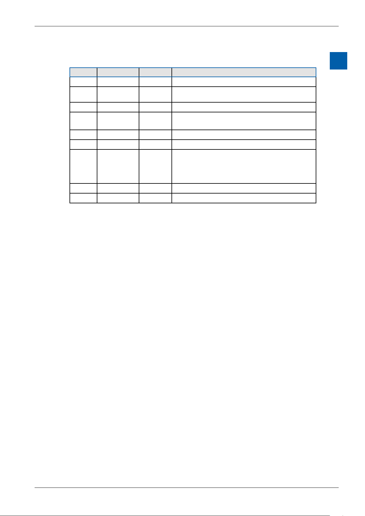
0.1 Documentversions
Version Published Redactor Remarks
EN01 2012-10-10 ErDa First version of manual
EN02 2012-11-28 HaMa
EN03 2013-12-18 ErDa Chapter 7.6.2 Container variables removed
EN04 2013-05-31 HaMa Chapter 3.1.2 Description oft the communica-
EN05 2014-01-20 HaMa New logo and new company name
ENG06 2016-01-27 HaMa New xation set
ENG07 2019-06-20 HaMa - Added the crossed bin logo for “Waste of
0
■ Ch1.2 Connection SD » D and /SD » D
■ Ch3.1.1 Picture RS-485-Network replaced
tion modules PCD7.F1xxS for Slot A
Electrical and Electronic Equipment (WEEE)”
disposal
- copied from Word to InDesign
0.3 Brands and trademarks
Saia PCD® and Saia PG5®
are registered trademarks of Saia-Burgess Controls AG.
Technical modications are based on the current state-of-the-art technology.
Saia-Burgess Controls AG, 2012. © All rights reserved.
Published in Switzerland
Manual PCD7.D412DTPF & PCD7.D4xxxT5F │ Document 27-620 – Release ENG07 │ 2019-06-20
0-4

Saia-Burgess Controls AG
1 Quickstart
Quickstart
Introduction | Denition of the connectors
1.1 Introduction
This manual covers the technical aspects of the PCD7.D412DTPF SVGA MB panel and the PCD7.D4xxxT5F programmable pWeb panel. The aim of the Quickstart
chapter is to facilitate the rapid installation of components of the PCD7.D4xxxT5F.
The following are discussed:
■ Denition of the connectors
■ Power supply and consumption
■ Dimensions
■ Possible communications modes
In other chapters, more details can be found about:
■ Hardware
■ Software (Setup menu step-by-step and conguration)
■ Usage, rmware update, etc.
■ Maintenance
Complementary manuals:
■ PG5 2.0 User guide | 26-732
■ File System and FTP Server | 26-855
■ Ethernet TCP/IP | 26-766
■ Smart RIO PCD3.T665 | 26-892
■ PCD3 series (conguration of the communications interfaces) | 26-789
1
1.2 Denitionoftheconnectors
PROTECTIVE EARTH MUST BE CONNECTED!
Manual PCD7.D412DTPF & PCD7.D4xxxT5F │ Document 27-620 – Release ENG07 │ 2019-06-20
1-1

Saia-Burgess Controls AG
Connections
Power Supply PCD7.F1xxS
Connector
pins
RS 485
Connector
pins
Signal
1 24 V (+)
2 GND (-)
Signal
1 GND
2 NC
3 /D
4 D
Quickstart
Denition of the connectors | Voltage supply of the panel
Connector
pins
0 GND GND
1 TXD232 SD
2 RXD232 /SD
3 RTS232
4 CTS232
5 GND GND
6 DTR232
7 DSR232
8 COM232
9 DCD232
Signal
RS 232
Signal
RS 485
1
Power supply
Communications
Reset button
Earth (-) / 24V (+) Connector, 2-pole
2× Ethernet (switch !) 2× RJ-45 with LED indicator
USB Standard USB slave
Pushbutton
1.3 Voltage supply of the panel
Pin Signal
1 24V (+)
2 Earth (-)
Current supply:
→ 24 VDC +30% / –20%
or
→ 19 VAC ±15% current supply with full-wave rectier
Current consumption Power output without back-
PCD7.D412DT5F
PCD7.D410VT5F
PCD7.D457VT5F
PCD7.D412DTPF Max 600 mA 5 W
Max 600 mA
Max 600 mA
max 500 mA
light
5 W
5 W
5 W
Current supply with jack plug for cable of max. 1.5 mm2.
Manual PCD7.D412DTPF & PCD7.D4xxxT5F │ Document 27-620 – Release ENG07 │ 2019-06-20
1-2

Saia-Burgess Controls AG
1.4 Dimensions and cut-out (in mm)
1.4.1 12.1" panel
62 6
Quickstart
Dimensions and cut-out (in mm)
1
Front panel W × H, 319 × 264
Display W × H, 245 × 185
1.4.2 10.4" panel
Front panel W × H, 281 × 221
Display W × H, 211 × 150
1.4.3 5.7" panel
Cut-out W × H, 300 × 244
62 6
Cut-out W × H, 262 × 202
50 6
Front panel W × H, 202 × 156
Display 5.7" W × H, 117 × 88
Manual PCD7.D412DTPF & PCD7.D4xxxT5F │ Document 27-620 – Release ENG07 │ 2019-06-20
Cut-out W × H, 189 × 142
1-3

Saia-Burgess Controls AG
1.5 Installation of the panels
1.5.1 Installation in control cabinet
■ The installation position is horizontal. Slide the unit into the installation cut-out.
■ Make sure that the ventilation slots are not covered, to allow air circulation and
the device does not overheat.
■ Install 4 mounting clamps for 5.7" (2 on top and 2 on the bottom), 6 clamps for
10.4" (2 on top, 2 on the bottom and 2 on the sides) and 8 clamps for the 12.1"
(3 on top, 3 on the bottom and 2 on the sides). Refer to the photos below.
Quickstart
Installation of the panels
1
Mounting parts of 12.1" panels
Mounting parts of 10.4" panels
Mounting parts of 5.7" panels
Note:
■ It is helpful to have somebody hold the unit from the front side of the panel
while the brackets are being installed.
■ The bolts require a 2.5 mm Allen key.
■ Screw the bolts into the brackets up to the point when you can still clip them
onto the MicroBrowser without being obstructed by the plate.
■ Clip them onto the unit then tighten the bolts until they touch the plate.
■ The required torque to seal the gasket is 20 cNm. To avoid breaking the clamp,
do not exceed 30 cNm.
How to ensure spray water protection according to IP65:
The device must be mounted on a at surface or wall. Tighten the bolts until the
front plate of the PCD7.D4xx is just touching the mounting surface/wall.
Manual PCD7.D412DTPF & PCD7.D4xxxT5F │ Document 27-620 – Release ENG07 │ 2019-06-20
1-4

Saia-Burgess Controls AG
1.5.2 Drywall mounting set for MB panels
The MicroBrowser panels are not just for mounting in the control cabinet; They
also look very good in the oce or living room, or mounted on a wall. This is why
we provide wall mounting kits for solid and cavity wall mounting.
Quickstart
Installation of the panels | Operation and handling
1
In-wall
Mounting kit for the 5.7” MB panel PCD7.D457-IWS2 PCD7.D457-OWS2
Mounting kit for the 10.4” MB panel PCD7.D410-IWS PCD7.D410-OWS
Mounting kit for the 12.1” MB panel PCD7.D412-IWS PCD7.D412-OWS
On-wall
In-wall(cavitywalls) On-wall (solid walls)
1.6 Operation and handling of the touchscreen
To operate the touchscreen, use only your nger, the stylus or a soft nger stylus.
Do not use sharp tools (e.g., sharp metallic objects, paperclips or a screwdriver,
etc.).
Manual PCD7.D412DTPF & PCD7.D4xxxT5F │ Document 27-620 – Release ENG07 │ 2019-06-20
1-5

Saia-Burgess Controls AG
Setting up communications for displaying a website
1.7 Setting up communications for displaying a website
1.7.1 HTTPDirectoverethernetRJ-45connector
The quickest communications port is the ethernet port via RJ-45, with the HTTP
Direct protocol selected. The speed is either 10 MBit/s or 100 MBit/s after an autonegotiation protocol with the connected device.
Internal connection for programmed pWeb panels
The programmed panels are connected internally directly to the programmable
logic controller, via an ethernet connection. It therefore suces, in this case, to
simply set the local host IP address 127.0.0.1 and HTTP Direct connection in the
Setup menu under Web connection. The programmable pWeb panels are obviously also capable of displaying websites from controllers located within the network.
The procedure for this is the same as with the standard 12” SVGA panel.
Connectingtoexternaldevices
If an ethernet connection to an Automation Server exists, the HTTP connection
can be established between our PCD7.D4xx and any SBC controller. In the case
of the programmable panels, the panel is generally connected to the internal con-
troller.
Quickstart
1
Ethernet http direct
Quick test of the SVGA panel
■ First the Saia PCD must have a web program loaded which was created with
the Web Editor (see 26-838_Manual_Web-Editor). You can ask the SBC Support Team for some examples. They will also soon be available on our website.
■ Using a CAT5 cable, you can connect our PCD7.D4xx terminal to the SBC
device. The current controllers support auto-crossing; a crossover cable is thus
no longer required.
■ Using PG5, dene the HW settings of the Saia PCD device: S-bus support
must be selected together with the TCP/IP channel where a valid IP address is
entered.
Manual PCD7.D412DTPF & PCD7.D4xxxT5F │ Document 27-620 – Release ENG07 │ 2019-06-20
1-6

Saia-Burgess Controls AG
Setup settings of the SVGA panel:
Congure the SVGA panel by opening the Setup menu (refer to chapter 5):
Quickstart
Setting up communications for displaying a website
Î First, be sure that you are on the same network subnet. For example, if the
Saia PCD has the IP address 192.168.12.92, give your terminal (in the Network
menu) an IP address like 192.168.12.90, as normally the subnet mask is set to
255.255.255.0.
Î In the Conguration menu, enter the Address of the start page that corre-
sponds to the IP address of the Saia PCD, and also enter its HTML start page
name.
Your MB panel should now be connected to the Saia PCD and the start page selection should be displayed on the screen. You can now navigate your web pages.
1.7.2 USBportasServiceport
The USB port on the programmable panels is used mainly to download the user
program onto the controller with PG5.
On SVGA standard MB panels, this port is generally used as a Service port. It is
used mainly to download new rmware programs onto the device.
The USB port meets the USB 1.1 specication. Maximum speed: 12 MBit/s.
1.7.3
Getting started with the Web Editor on the MicroBrowser panel PCD7.D4xx
1
Detailed documentation can be downloaded from our website. See manual 26-838
Manual Web Editor. To get started with programming the MB panel, some particular features must be observed:
■ If no assistance is available from the Wizard when creating a new project, the
project must be set up as follows:
● Using the virtual keyboard with SVGA MB panels
● See Chapter 5.6 Keyboard
● If you want to use the le Background.teq or foreground.teq, you rst need
to generate these les. Why is this? Before objects or text and elds can appear, these les must rst be positioned on each page.
● Once the project is ready to download, enter the desired HTML le name
and generate a Build Project. Then make a Webserver Build in the Saia PG5
Project Manager, so that all the les are held in the PCD. If you just want to
access the PCD with MB panel PCD7.D4xx and not with a PC browser, you
can reduce the amount of data by deleting the .jar les, as they are already
included on the panel.
Manual PCD7.D412DTPF & PCD7.D4xxxT5F │ Document 27-620 – Release ENG07 │ 2019-06-20
1-7

Saia-Burgess Controls AG
Technical data of the SVGA MicroBrowser panel
2 Technical data for the two panel types
The hardware of the SVGA MicroBrowser panels and the programmable pWeb
panels is dierentiated in several areas by the Programmable Logic Controller on
the pWeb panels. These are described in the following sections:
2.1 Technical data of the SVGA MicroBrowser panel
Display
Display size 12.1" TFT
Resolution SVGA 800 × 600
Backlight LED
Colours 65,536
Contrast adjustment Ye s
On Board File System 128 MByte
Operating system
Internetservices
Interfaces
Ethernet 10 / 100 M 2× RJ45 (switch)
Current consumption
Voltage supply
Protection class (front)
Temperature
Relativehumidity
Processor
Real Time Clock (RTC)
Saia PCD COSinuS with SBC MicroBrowser expansion
Automation Server, SBC MicroBrowser
Max 600 mA
24 VDC±20 %
IP65
Operation: 0 … 50°C
Storage: –25 … +70°C
Operation: 10 … 80%
Storage: 10 … 98% (non-condensing)
Coldre CF5373L, 240 MHz
Yes, with Supercap
Technical data
2
Manual PCD7.D412DTPF & PCD7.D4xxxT5F │ Document 27-620 – Release ENG07 │ 2019-06-20
2-1
Saia-Burgess Controls AG
Technical data of the SVGA MicroBrowser panel
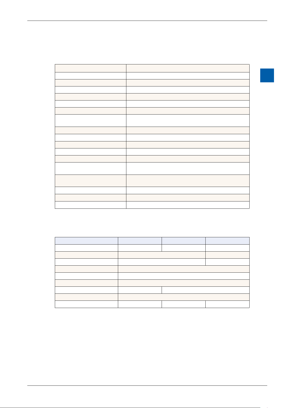
2.2 Technical data for the pWeb panels
2.2.1 Overview
Logic controller
User program, ROM /DB/text 1 MByte
RAM/DB/text 1 Mbyte
Media 14,336 ags / 16,384 registers
Backup for user User program is saved to the integrated micro SD card
File system for user 128 MBytes, on-board
Program cycle time 10 cycles / sec maximum
Protocolsoneldlevel
Internetservices
Interfaces
Ethernet 10 / 100 M 2× RJ45 (switch)
USB (1.1 / 2.0) 1× client
Serial interfaces RS-485 & socket for PCD7.F1xxS communications module
Temperature range
Relativehumidity
Processor
Real Time Clock (RTC)
Battery
Serial-S-bus, Ether-S-bus, Ether-S-I/O, Modbus RTU,
TCP or M-bus
SBC MicroBrowser, Automation Server
Operation: 0 … 50°C
Storage: –25 … +70°C
Operation: 10 … 80%
Storage: 10 … 98% (non-condensing)
Coldre CF5373L, 240 MHz
Yes, with battery back-up
Lithium Renata CR 2032 (lifetime 1-3 years)
Technical data
2
2.2.2 Product-related presentation
Technical data PCD7.D457VT5F PCD7.D410VT5F PCD7.D412DT5F
Display size 5.7 TFT 10.4 TFT 12.1 TFT
Resolution/Pixels VGA 640 × 480 SVGA 800 × 600
Touchscreen Resistive four-wire Resistive ve-wire
Contrast adjustment yes
Backlight LED
Voltage supply 18 - 32V
Current consumption Max. 500 mA Max. 600 mA
Protection class (front) IP 65
Front status LED No No Yes
Manual PCD7.D412DTPF & PCD7.D4xxxT5F │ Document 27-620 – Release ENG07 │ 2019-06-20
2-2

Saia-Burgess Controls AG
2.2.2 Battery of the pWeb panel
The hardware components are maintenance-free, with the exception of the CPUs
for the pWeb panel, whose battery requires occasional replacement.
Technical data
Technical data of the SVGA MicroBrowser panel
The components do not contain any user-replaceable parts. If hardware problems
occur, please return the components to Saia-Burgess Controls.
The resources (register, ags, timer, counters, etc.) and the character strings/DBs
are stored in the RAM. In order to prevent these from being lost, and to enable
the hardware clock to carry on running during a power failure, the devices are
equipped with a back-up battery:
CPU model Buer Buertime
PCD7.D4xxx Renata CR 2032 lithium battery 1-3 years
1)
Depending on the ambient temperature: The higher the temperature, the shorter the buer time.
1)
New controllers include batteries in the scope of delivery, and these must be
inserted during commissioning. Pay attention to the polarity of the batteries.
CPUs with lithium batteries are not maintenance-free. The battery voltage is monitored by the CPU. The status LED lights up (12” pWeb panel only) and XOB 2 is
called if:
■ the battery voltage is lower than 2.4 V;
■ the battery is missing.
2
In order to avoid data-loss, we recommend changing the batteries while the panel
is connected to the power supply.
■ Disconnect from the voltage supply.
■ Remove the cover of the pWeb panel.
■ To prevent data loss while changing the battery 119B, reconnect to the voltage
supply.
■ Push the terminal holder back slightly (see arrow in gure).
■ Remove the battery.
■ Insert a Renata CR 2032 button battery so that the positive terminal is in con-
tact with the terminal holder.
■ Disconnect from the voltage supply and reattach the back wall of the panel.
Manual PCD7.D412DTPF & PCD7.D4xxxT5F │ Document 27-620 – Release ENG07 │ 2019-06-20
2-3

Saia-Burgess Controls AG
Communications interfaces
3 Logic controller of the programmable pWeb panel
3.1 Communications interfaces
Various communications interfaces are integrated into the programmable logic
controller. These can also be expanded by installing an additional module.
Logic Controller
3.1.1 On-board RS-485
PCD4.DxxxT5F PCD3.Mxxxx PCD2.M5xxx PCD1.M2xxx
GND
/D
D
The pin nos of the connected PCD are explained in the respective manual.
Make sure that the terminators are properly terminated.
In the example below, you can see a possible connection between the terminals
and PCDs. In order to avoid reection on the communications channel, the network should be terminated with termination resistors. The PCD7.D4xx has a switch
for this:
3
RS-485-Network
Pull up
330 Ohm
Termination
Resistor
150 Ohm
Pull down
330 Ohm
First station Middle stations
PCD1.M2_
Port #1
+5 V
/n
n n
PCD1.M2_
PCD2.M5_
n n
Bus RS485
Segment length max. 1200 m
PCD3.Mxxxx
max. 32 stations
End station
PCD7.D457VT5F
PCD7.D410VT5F
PCD7.D412DT5F
+5 V
/n/n
/RX - /TX
RX - TX
/n
Manual PCD7.D412DTPF & PCD7.D4xxxT5F │ Document 27-620 – Release ENG07 │ 2019-06-20
3-4

Saia-Burgess Controls AG
Thefollowinggureshowsyouwhereitislocated.
Î If the switch is in the top position, the network is closed.
Î If the switch is in the bottom position, the network is open.
Conguration can either be performed directly, via the Setup menu on the pWeb
panel, or indirectly, via the Hardware conguration on the PG5. Overwrite the
current conguration the same as when making a change.
Logic Controller
Communications interfaces
3
3.1.2 Additional communications ports using slot A (Port no. 1)
Slot A on the pWeb panels allows you to plug in optional modules for communications interfaces. Only modules of the PCD7.F1xxS series are supported.
Installation - PCD7-D412DT5F
Earth 2 × Ethernet
(switch)
USB Reset
Switch
PCD7.F1xxS RS-485 Power Supply
Multi-colored front LED
Manual PCD7.D412DTPF & PCD7.D4xxxT5F │ Document 27-620 – Release ENG07 │ 2019-06-20
3-5

Saia-Burgess Controls AG
Installation - PCD7.D410VT5F
Logic Controller
Communications interfaces
Earth 2 × Ethernet
(switch)
Installation - PCD7.D457VT5F
Earth 2 × Ethernet
(switch)
USB Reset
Switch
USB Reset
Switch
PCD7.F1xxS RS-485 Power Supply
3
PCD7.F1xxS RS-485 Power Supply
Connections
PCD7.F1xxS
Connector
pins
0 GND GND
1 TXD D
2 RXD /D
3 RTS
4 CTS
5 GND GND
6 DTR
7 DSR
8 COM
9 DCD
Signal
RS-232
Signal
RS-485
RS-485
Connector
pins
1 GND
2 NC
3 /D
4 D
Power Supply
Connector
pins
1 24 V (+)
2 GND (-)
Signal
Signal
Manual PCD7.D412DTPF & PCD7.D4xxxT5F │ Document 27-620 – Release ENG07 │ 2019-06-20
3-6

Saia-Burgess Controls AG
3.1.2.1 PCD7.F110S Serial Interface Module RS-485/RS-422
Termination resistors can be connected (CLOSED) or disconnected (OPEN) with
slide switchs.
PCD7.F110S RS-485 terminator
Slider
O
C
21
Open not terminated
(factory setting)
Logic Controller
Communications interfaces
3
Slider
O
C
21
Closed terminated
RS-422 connection
Port x.1 - 10 pin spring-loaded terminal block
RS-422
0 PGND Tx 1
2 /Tx Rx 3
4 /Rx PGND 5
6 RTS /RTS 7
8 CTS /CTS 9
Terminal
Pin
PGND 10
TX 11
/TX 12
RX 13
/RX 14
PGND 15
RTS 16
/RTS 17
CTS 18
/CTS 19
RS-422
Peripherie-
device
PGND
TX
/TX
RX
/RX
SGND
RTS
/RTS
CTS
/CTS
RS 485 connection (Electrically connected RS-485 interface)
Port x.1 - 10 pin spring-loaded terminal block
RS-485
0 PGND Rx-Tx 1
2 /Rx-/Tx 3
4 PGND 5
6 7
8 (SGD) 9
PCD Modul
RX - TX
/RX - /TX
Terminal
x0
x1
x2
RS-485
GND
RS-485
RS-485
Peripherie-
device
PGNDPGND
RX - TX
/RX - /TX
For more details, see Manual 26-740, section "Installation components for RS-485
Networks."
Manual PCD7.D412DTPF & PCD7.D4xxxT5F │ Document 27-620 – Release ENG07 │ 2019-06-20
3-7

Saia-Burgess Controls AG
3.1.2.2 PCD7.F121S Serial interface module RS-232 suitable for modem connection
PCD7.F121S
RS-232 connection
Port x.1
RS-485
0 PGND TxD 1
2 RxD RTS 3
4 CTS PGND 5
6 DTR DSR 7
8 COM DCD 9
10 pin spring-loaded terminal block
Logic Controller
Communications interfaces
3
RS-232 connection to DTE RS-232 connection to DCE
cable
External modem
(ETCD) DCE
PGND
TX
RX
RTS
CTS
SGND
DTR
DSR
DCD
0 PGND
1 TXD
2 RXD
3 RTS
4 CTS
5 PGND
6 DTR
7 DSR
8 Reserve
9 DCD
cable
Peripherie
device (DTE)
PGND
TX
RX
RTS
CTS
SGND
DTR
DSR
DCD
0 PGND
1 TXD
2 RXD
3 RTS
4 CTS
5 PGND
6 DTR
7 DSR
8 Reserve
9 DCD
Manual PCD7.D412DTPF & PCD7.D4xxxT5F │ Document 27-620 – Release ENG07 │ 2019-06-20
3-8
Saia-Burgess Controls AG
Communications interfaces
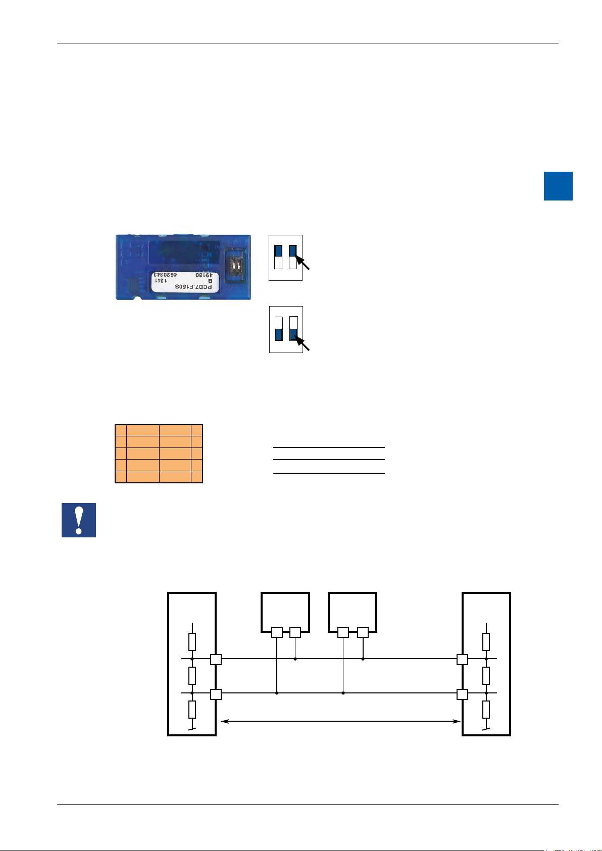
3.1.2.3 PCD7.F150S Serial Interface Module RS-485 with Electrical Isolation
Electrical isolation is achieved with three optocouplers and a DC/DC converter.
Data signals are protected against overvoltage with an anti-surge diode (10 V).
Electrical isolation is achieved using three optical couplers and a DC/DC converter.
The data signals are protected against excess voltages by a suppressor diode
(10 V).
The line terminator for port x.1 is integrated into the module and can be activated
using the silde switch on the module.
PCD7.F150S RS-485 terminator
ON
C
O
1 2
ON
C
O
1 2
Closed terminated
Slider
Open not terminated
(factory setting)
Logic Controller
3
Slider
RS 485 connection - 10 pin spring-loaded terminal block
Port x.1
RS-485
0 PGND Rx-Tx 1
2 /Rx-/Tx 3
4 PGND 5
6 7
8 (SGD) 9
PCD Modul
RX - TX
/RX - /TX
Terminal
x0
x1
x2
RS-485
GND
RS-485
RS-485
Peripherie-
device
PGNDPGND
RX - TX
/RX - /TX
When using this module, the permitted ambient temperature for the control unit is
reduced by 5°C.
Line terminator:
First station Middle stations End station
+5 V
/n
Pull up
330 Ohm
Termination
Resistor
150 Ohm
Pull down
330 Ohm
+5 V
n n
28
Bus RS-485
29 n
Segment length max. 1200 m
max. 32 stations
/n/n
/RX - /TX
RX - TX
More details are available in the manual 26-740 “Installation components for
RS-485 networks”.
Manual PCD7.D412DTPF & PCD7.D4xxxT5F │ Document 27-620 – Release ENG07 │ 2019-06-20
3-9

Saia-Burgess Controls AG
3.1.2.4 PCD7.F180S Serial Interface Module Belimo MP-Bus
Up to 8 actuators and sensors can be connected.
PCD7.F180S
Belimo connection
Port x.1
Belimo MP-Bus
0 PGND MP 1
2 ‘MFT’ ‘IN’ 3
4 PGND 5
6 7
8 (SGD) 9
10 pin spring-loaded terminal block
Logic Controller
Communications interfaces
3
MP-Bus cabling
0 PGND Earth connection, MP line
1 MP Multi-point
The MP-Bus is the Belimo master slave
bus. Up to 8 slaves can be connected to
a master device.
These are:
■ MFT(2) ap drives
■ MFT(2) valve drives
■ MFT re damper drives
■ VAV NMV-D2M compact controller
2 ‘MFT’ MFT programming unit (internal MP-Bus)
3 ‘IN’ detection of MFT programming unit
(input 10 kΩ, Z5V1)
5 PGND Earth connection, MFT programming unit
Manual PCD7.D412DTPF & PCD7.D4xxxT5F │ Document 27-620 – Release ENG07 │ 2019-06-20
3-10
 Loading...