


TARGHETTA TECNICA
MANUALE D’USO
GEBRAUCHSANWEISUNG
INSTRUCTION MANUAL
MANUEL D’USAGE
MANUAL DE USO
HANDLEIDINGEN
PУКОВОДСТВО ПО ЭКСПЛУАТАЦИИ
3075910
BASI REFRIGERATE
KÜHLTISCHEN
REFRIGERATED COUNTERS
TABLES REFRIGEREES
BASES CONGELAD
GEKOELTEN GRONDSLAGEN
ОСНОВЫ РЕФРИЖИРАТОРОВ
Rev.3 09/2007

IT
indicazioni riguardanti la sicurezza d’uso e di manutenzione
Leggere attentamente le avvertenze contenute nel presente libretto in quanto forniscono importanti
Conservare con cura questo libretto per ogni ulteriore consultazione dei vari operatori
Il costruttore si riserva il diritto di apportare modifiche al presente manuale, senza preavviso e responsabilità
as to safety during installation , use and maintenance
GB
alcuna.
Carefully read the instructions contained in this handbook. You may find important recommendations
This handbook is to be Kept for further use by operators
The Manufacturer is not liable for any changes to this handbook, which may be altered without prior notice.
Die in diesem Büchlein enthaltenen Hinweise genau durchlesen, da sie wichtige Anweisungen für
die Sichertheit bei installation, Gebrauch und Wartung liefem
DE
Bewarhen Sie dieses Büchlein für jede weitere Befragung seitens der verschiedenen Bedienern gut auf
FR
instructions concernant la sécurité d’installation,d’emploi et d’entretien
ES
NL
Dit boekje zorgvuldig bewaren voor iedere verdere raadpleging door de verschillende bedieners.
RU
Der Hersteller behält sich das Recht, Änderungen dieser Gebrauchsanweisung ohne Ankündigung und ohne
Übernahme der Verantwortung vornehmen zu können.
Lire attentivement les instructions contenues dans ce livret car elles donnent d’importantes
Garder soigneusement ce livret pour toute consultation nécessaire aux différents opérateurs
Le constructeur se réserve le droit d'apporter des modifications à ce manuel, sans préavis ni responsabilité
d'aucune sorte.
Lea con atenciòn las advert que encuentra en este manual , ya que le dan importantes indicationes
reguardo a la seguridad de la instalaciòn, del uso y de la manutenciònencias
Conserve cuidadosamente este manual que le servirà para las pròximas consultaciones de los varios
operadores
El constructor se reserva el derecho de hacer modificas al actual manual, sín dar algún preaviso y sín
responsabilidad alguna.
De waarschuwingen, die in dit boekje staan, aandachtig doorlezen, omdat deze belangrijke
aanwijzingen geven betreffende de gebruiksveiligheid en het onderhoud.
De fabrikant behoudt zich het recht voor om veranderingen in deze handleiding aan te brengen, zonder
voorafgaande waarschuwing en zonder enkele aansprakelijkheid.
Прочитать внимательно примечания, содержащиеся в настоящем руководстве, т.к. они
представляют важные сведения, относящиеся к технике безопасности и эксплуатации.
Бережно сохранять это руководство для дальнейшей консутации её другим рерсоналом.
Конструктор сохраняет за собой право вносить изменения в настоящие руководство без
предупреждения и любой ответственности, без
2

Misure di ingombro
Overall dimensions
Abmessungen
Dimensions d’encombrement
Medidas máximas
Omvangsafmetingen
Габариты
Dati Tecnici - I dati tecnici sono riportati in un apposito foglio allegato
Technical Data – The technical data are indicated in the enclosed sheet.
Technische Daten - Die technischen Daten sind auf einem gesorderten Blatt angegeben
Données Techniques - Les donnèes techniques sont dètaillèes dans une fiche annexèe
Datos técnicos – Los datos técnicos figuran en un documento especial anexo.
Technische gegevens – De technische gegevens zijn op een afzonderlijk blad in bijlage weergegeven.
Технические данные – Технические данные занесены в специальное приложение.
3

INDICE
DESCRIZIONE MACCHINA 5
ETICHETTA DI IDENTIFICAZIONE 5
NOTE GENERALI ALLA CONSEGNA 5
PRESCRIZIONI DI SICUREZZA 5
CARATTERISTICHE TECNICHE 6
MESSA IN OPERA ED INSTALLAZIONE 6
PANNELLI DI COMANDO 7
AVVIAMENTO E FUNZIONAMENTO 7
SETPOINT DI LAVORO E PARAMETRI DI CONFIGURAZIONE 8
CARICAMENTO PRODOTTO 10
ARRESTO 10
SBRINAMENTO 10
ALLARMI 10
IRREGOLARITA’ DI FUNZIONAMENTO 10
PULIZIA GIORNALIERA 10
MACCHIE DI CIBO E RESIDUI INDURITI 11
PULIZIA E MANUTENZIONE GENERALE 11
INTERRUZIONI D’USO 11
CONSIGLI PER LA MANUTENZIONE DELL’ACCIAIO INOSSIDABILE 11
SMALTIMENTO 11
SCHEDA TECNICA DEL REFRIGERANTE 12
4

DESCRIZIONE MACCHINA
Quest’apparecchiatura è stata progettata per la refrigerazione
e conservazione degli alimenti. Ogni altro uso è da ritenersi
improprio.
ATTENZIONE: le macchine non sono idonee per installazioni
all’aperto e/o ambienti sottoposti alle azioni degli agenti
atmosferici.
Il costruttore declina ogni responsabilità da usi non
previsti delle apparecchiature.
Le basi hanno nella parte superiore un piano di lavoro
disponibile anche con alzatina posteriore; sono disponibili
anche prodotti senza piano con analoghe capacità refrigeranti
I comandi sono con termoregolatore digitale ed interruttore
generale.
Il gruppo motore è posto a sinistra della base in un opportuno
alloggiamento.
L’evaporatore è posto all’interno del vano refrigerato, uno per
ogni vano ed è protetto con apposite lamiere.
La ventilazione interna è realizzata con ventilatori tangenziali
protetti posti al di sopra dell’evaporatore.
L’apparecchio è dotato di evaporazione automatica della
condensa.
ETICHETTA DI IDENTIFICAZIONE
L’etichetta di identificazione è riportata stabilmente sul
prodotto e fornisce una serie di indicazioni importanti sulle
caratteristiche tecniche e costruttive del prodotto.
NOTE GENERALI ALLA
CONSEGNA
Alla consegna verificare che l’imballo sia integro e che durante
il trasporto non abbia subito danni.
Verificare che le caratteristiche del prodotto corrispondano alle
specifiche dell’ordine richiesto. Se così non fosse mettersi
immediatamente in contatto con il rivenditore.
Nel complimentarci per la scelta ci auguriamo che possiate
utilizzare al meglio le nostre basi refrigerate seguendo le
indicazioni e le precauzioni necessarie contenute in questo
manuale.
Ricordate che è vietata qualsiasi riproduzione del manuale e
che , per una costante ricerca indirizzata alla innovazione e al
miglioramento delle qualità tecnologiche, le caratteristiche qui
riportate potrebbero cambiare senza preavviso.
PRESCRIZIONI DI SICUREZZA
ATTENZIONE : prima di qualsiasi operazione di manutenzione
o pulizia isolare l’apparecchiatura da fonti di energia elettrica
Portare l’interruttore generale nella posizione OFF;
TQPN
CONTENUTO CAMPI TARGHETTA TECNICA
1) modello
2) azienda costruttrice
3) sigla marcatura CE
4) anno di costruzione
5) n° di matricola
6) classe di isolamento elettrico
7) classe di protezione elettrica
A) tensione di alimentazione elettrica
B) intensità di corrente elettrica
C) frequenza nominale
D) potenza nominale
E) potenza nominale lampade
F) corrente fusibile
G) tipo gas refrigerante
H) quantità gas refrigerante
L) classe di temperatura impianto frigorifero
M) pressione max di alimentazione
N) portata ventilatore
P) velocità di rotazione ventilatore
Q) prevalenza ventilatore
R) Simbolo RAEE
S) portata vapore
T) pressione vapore
W) potenza elementi riscaldanti
Per qualsiasi comunicazione con il costruttore citare sempre il
NUMERO DI MATRICOLA della macchina.
Togliere la spina;
ATTENZIONE : non impiegare prese o spine non provviste di
messa a terra.
La presa di rete deve essere provvista di MESSA A TERRA.
5

ATTENZIONE : non usare per il collegamento alla rete
adattatori o prolunghe.
ATTENZIONE : le operazioni di messa in opera e di
installazione devono essere effettuate da personale
specializzato.
Rimuovere la scatola imballo facendo attenzione a non
ammaccare le superfici dell’apparecchio.
ATTENZIONE : attendere il tempo necessario al
raggiungimento della temperatura impostata prima di inserire il
cibo da conservare.
Coprire sempre gli alimenti con le apposite pellicole prima di
inserirli negli apparecchi.
ATTENZIONE : non introdurre negli apparecchi bevande o cibi
caldi.
ATTENZIONE : non effettuare le pulizie delle zone circostanti
gli apparecchi quando la porta è aperta.
Non lavare l’apparecchiatura con getti di acqua diretti e ad alta
pressione.
ATTENZIONE : non usare sostanze a base di cloro
(candeggina , acido muriatico ,ecc ) o comunque tossiche per
la pulizia o in vicinanza degli apparecchi.
La pulizia e la manutenzione dell’impianto refrigerante e della
zona compressore richiede l’intervento di un tecnico
specializzato e autorizzato, per questo motivo non può essere
effettuato da personale non idoneo.
Per interventi di manutenzione o in caso di anomalie
disinserire completamente l’apparecchiatura; richiedere
l’intervento del SERVIZIO ASSISTENZA ad un centro
autorizzato e impiegare per le eventuali sostituzioni ricambi
originali. L’inadempienza di quanto sopra può compromettere
lo stato di sicurezza degli apparecchio.
CARATTERISTICHE TECNICHE
Le caratteristiche tecniche sono riportate nell’apposito foglio
allegato al manuale di istruzione
MESSA IN OPERA ED
INSTALLAZIONE
Gli apparecchi vengono sempre spedite su pallet e con imballo
in cartone di protezione.
Al ricevimento e dopo aver effettuato lo sballaggio in caso di
danni o parti mancanti comportarsi come descritto al capitolo
“NOTE GENERALI ALLA CONSEGNA”
ATTENZIONE : gli elementi dell’imballaggio ( sacchetti in
plastica , polistirolo espanso , chiodi ecc. ) non devono essere
lasciati alla portata dei bambini in quanto potenziali fonti di
pericolo.
Con un carrello a forche
sollevare l’apparecchio e
portarlo sul luogo di
installazione facendo
attenzione che il carico
non sia sbilanciato.
ATTENZIONE: sia per il posizionamento sul posto di
installazione come per gli spostamenti futuri non spingere o
trascinare l’apparecchio, per evitare che si ribalti o creare
danni ad alcune parti dello stesso
ATTENZIONE : non posizionare l’apparecchio vicino a fonti di
calore o in ambienti con temperatura elevate; questo potrebbe
causare minor rendimento dello stesso e una eccessiva
sollecitazione dell’impianto di refrigerazione
Togliere la pellicola protettiva
dal prodotto. Questa
operazione può produrre
scosse fastidiose anche se non
pericolose (elettricità statica).
L’inconveniente si elimina o si
riduce sostanzialmente
mantenendo una mano sempre
a contatto con l’apparecchio o
collegando a terra l’involucro
esterno.
A questo punto è possibile
regolare i piedi dell’apparecchio
per livellarlo.
Livellare l’apparecchio
tenendolo leggermente inclinato
sul retro per facilitare la
chiusura ottimale delle porte
Pulire con acqua tiepida e sapone neutro ( come descritto al
capitolo “PULIZIA” ) e montare gli eventuali accessori
6

L’apparecchio è dotato di spina elettrica di tipo SHUCO
Verificare la corrispondenza della stessa alle norme EN60320,
EN60335-1 e alle norme nazionali. Sostituire la spina con una
a norme in caso di non corrispondenza.
ATTENZIONE : l’operazione deve essere effettuata da un
tecnico specializzato
Verificare che la tensione di
rete corrisponda a quella
riportata sulla targhetta delle
caratteristiche tecniche
dell’apparecchio.
ATTENZIONE : verificare che la presa di rete sia predisposta
di messa a terra ; in caso contrario provvedere.
Inserire quindi la spina di rete nell’apposita presa di rete
A questo punto le operazioni di messa in opera sono
terminate.
L’apparecchiatura deve essere inoltre
inclusa in un sistema equipotenziale
la cui efficienza deve essere verificato
secondo le norme in vigore . Il
collegamento viene effettuato
mediante una vite contrassegnata
dalla sigla “Equipotenziale “ posta
nella zona compressori.
PANNELLI DI COMANDO
Tutti gli apparecchi della gamma montano cruscotti
portacomandi con i seguenti comandi :
1) interruttore generale
2) interruttore doppia umidità
3) termoregolatore
AVVIAMENTO E
FUNZIONAMENTO
Per avviare l’apparecchio eseguire le seguenti operazioni :
portare l’interruttore di linea in posizione ON
premere l’interruttore generale (1) ; si accenderà la spia verde
dell’interruttore generale;
a questo punto è possibile impostare la temperatura di
funzionamento tramite una adeguata impostazione del
Termoregolatore (3) tenendo presente le seguenti indicazioni :
- premendo il pulsante “
visualizzazione del SETPOINT indicato dal lampeggio del led
”. Agendo sui pulsante “ ” e “ ”, mantenendo
“
premuto il pulsante
di temperatura impostato;
- il pulsante “
SETPOINT ; tenendolo premuto si avrà un incremento più
veloce;
- il pulsante “
SETPOINT ; tenendolo premuto si avrà un decremento più
veloce;
- dopo la modifica rilasciare il pulsante “
tornerà automaticamente ad indicare il valore di temperatura
effettiva del vano;
- verificare sul display del termoregolatore (3) ,dopo un tempo
necessario ,che la temperatura interna degli apparecchi
corrisponda alla temperatura impostata.
A questo punto e non prima è possibile introdurre negli
apparecchi gli alimenti da conservare.
, sarà possibile modificare il valore
” ( fig. e ) incrementa i valori di
” ( fig. f ) decrementa i valori di
E’ possibile decidere il valore di umidità che si desidera a
seconda del tipo di alimenti che si vuole conservare.
Premendo il tasto (2) in posizione “I” si ottiene un grado di
umidità del 70%.
Premendo il tasto (2) in posizione “II” si ottiene un grado di
umidità del 90%.
fig. d
” ( fig.d ) si otterrà la
” ; il display
fig. e
1 2 3
fig. f
7

SETPOINT DI LAVORO E PARAMETRI DI CONFIGURAZIONE
Impostazione del setpoint di lavoro
• assicurarsi che la tastiera non sia bloccata e che non sia in corso alcuna procedura
• premere
• agendo su
• dopo la modifica premere
È inoltre possibile impostare il setpoint di lavoro attraverso il parametro SP.
Setpoint di lavoro
LABEL MIN. MAS. U.M. DEF. SETPOINT DI LAVORO
r1 r2 °C/°F (1) -2 setpoint di lavoro
Impostazione dei parametri di configurazione
Per accedere alla procedura:
• assicurarsi che non sia in corso alcuna procedura
• premere
• premere
• premere
• premere
• premere
Per selezionare un parametro:
• premere
Per modificare il valore di un parametro:
• premere
• premere
• premere
Per uscire dalla procedura:
• premere
Parametri di configurazione
LABEL MIN. MAS. U.M. DEF. SETPOINT DI LAVORO
SP r1 r2 °C/°F (1) -2 setpoint di lavoro
LABEL MIN. MAS. U.M. DEF. INGRESSI DI MISURA
CA1 -25 25 °C/°F (1) -0,5 offset sonda cella
CA2 -25 25 °C/°F (1) 0 offet sonda evaporatore
P0 0 1 - 1 tipo di sonda (0=PTC, 1=NTC)
P1 0 1 - 0
P2 0 1 - 0 unità di misura temperatura (2) (0=°C, 1=°F)
P3 0 2 - 1
P5 0 4 - 0
LABEL MIN. MAS. U.M. DEF. REGOLATORE
r0 0.1 15 °C/°F (1) 3,5 differenziale del setpoint di lavoro
r1 -99 r2 °C/°F (1) -2 minimo setpoint di lavoro
r2 r1 99 °C/°F (1) 8 massimo setpoint di lavoro
r3 0 1 - 0 blocco della modifica del setpoint di lavoro (1=SI)
LABEL MIN. MAS. U.M. DEF. PROTEZIONE COMPRESSORE
C0 0 240 min 0 ritardo compressore dall’accensione dello strumento
C1 0 240 min 5
C2 0 240 min 3 durata minima dello spegnimento del compressore
C3 0 240 s 10 durata minima dell’accensione del compressore
C4 0 240 min 10 durata dello spegnimento del compressore durante l’errore sonda cella; si veda anche C5
C5 0 240 min 10 durata dell’accensione del compressore durante l’errore sonda cella; si veda anche C4
LABEL MIN. MAS. U.M. DEF. SBRINAMENTO
d0 0 99 h 6
il LED lampeggerà
o entro 15 secondi sarà possibile modificare il valore di temperatura impostato
per confermare o, in alternativa, non operare per 15 secondi.
e per 4 sec; lo strumento visualizza “PA”
o entro 15 s per impostare “-19”
o non operare per 15 s
e per 4 sec; il display visualizza “SP”
o
o entro 15 s
o non operare per 15 s
e per 4 sec o non operare per 60 sec.
punto decimale grado Celsius (per la grandezza visualizzata durante il normale
funzionamento) (1=SI)
funzione della sonda evaporatore 0=sonda assente 1=sonda di sbrinamento e sonda per
la termostatazione del ventilatore dell’evaporatore 2=sonda per la termostatazione del
ventilatore dell’evaporatore
grandezza visualizzata durante il normale funzionamento 0=temperatura della cella
1=setpoint di lavoro 2=temperatura dell’evaporatore 3=“temperatura della cella temperatura dell’evaporatore”
tempo minimo tra due accensioni consecutive del compressore; anche ritardo
compressore dalla conclusione dell’errore sonda cella (3)
intervallo di sbrinamento; si veda anche d8(6) (0=lo sbrinamento a intervalli non verrà mai
attivato)

d1 0 1 - 0 tipo di sbrinamento (0=elettrico, 1=a gas caldo)
d2 -99 99 °C/°F (1) 8 temperatura di fine sbrinamento (solo se P3 = 1)
d3 0 99 min 30
d4 0 1 - 0 sbrinamento all’accensione dello strumento (1 = SI)
d5 0 99 min 0 ritardo sbrinamento dall’accensione dello strumento (solo se d4 = 1)
d6 0 1 - 1
d7 0 15 min 3 durata del gocciolamento
d8 0 2 _ 0
d9 -99 99 °C/°F (1) 0
dA 0 99 min 0
LABEL MIN. MAS. U.M. DEF. ALLARMI
A0 0 2 - 0
A1 -99 99 °C/°F (1) -2
A2 0 2 - 1
A4 -99 99 °C/°F (1) 15
A5 0 2 - 1
A6 0 240 min 120 ritardo allarme di temperatura di massima dall’accensione dello strumento (solo se A3 = 0)
A7 0 240 min 15 ritardo allarme di temperatura
A8 0 240 min 60
LABEL MIN. MAS. U.M. DEF. VENTILATORE DELL’EVAPORATORE
F0 0 4 - 1
F1 -99 99 °C/°F (1) -1
F2 0 2 - 0
F3 0 15 min 3 durata del fermo ventilatore dell’evaporatore
LABEL MIN. MAS. U.M. DEF. RETE SERIALE (MODBUS)
LA 1 247 - 1 indirizzo strumento
Lb 0 3 - 2
LP 0 2 - 2
(1) l’unità di misura dipende dal parametro P2
(2) impostare opportunamente i parametri relativi ai regolatori dopo la modifica del parametro P2
(3) se il parametro C1 è impostato a 0, il ritardo dalla conclusione dell’errore sonda cella sarà comunque di 2 min
(4) il differenziale del parametro è di 2,0 °C/4 °F
(6) lo strumento memorizza il conteggio dell’intervallo di sbrinamento ogni 30 min; la modifica del parametro d0 ha effetto dalla conclusione del precedente
intervallo di sbrinamento o dall’attivazione di uno sbrinamento in modo manuale
(7) il display ripristina il normale funzionamento quando, concluso il fermo ventilatore dell’evaporatore, la temperatura della cella scende al disotto di quella
che ha bloccato il display (o se si manifesta un allarme di temperatura)
(8) se il parametro P3 è impostato a 0 o 2, lo strumento funzionerà come se il parametro d8 fosse impostato a 0
(9) se all’attivazione dello sbrinamento la durata dell’accensione del compressore è inferiore al tempo stabilito con il parametro dA, il compressore rimarrà
ulteriormente acceso per la frazione di tempo necessaria a completarlo
(10) se il parametro P3 è impostato a 0, lo strumento funzionerà come se il parametro A0 fosse impostato a 0
(12) durante lo sbrinamento, il gocciolamento e il fermo ventilatore dell'evaporatore gli allarmi di temperatura sono assenti, a condizione che questi si siano
manifestati dopo l’attivazione dello sbrinamento
(14) se il parametro P3 è impostato a 0, lo strumento funzionerà come se il parametro F0 fosse impostato a 2
durata dello sbrinamento se P3 = 0 o 2; durata massima dello sbrinamento se P3 = 1
(0=lo sbrinamento non verrà mai attivato)
temperatura visualizzata durante lo sbrinamento 0=temperatura della cella 1=se
all’attivazione dello sbrinamento la temperatura della cella è al di sotto di “setpoint di
lavoro + r0”, al massimo “setpoint di lavoro + r0”; se all’attivazione dello sbrinamento la
temperatura della cella è al di sopra di “setpoint di lavoro + r0”, al massimo la temperatura
della cella all’attivazione dello sbrinamento(7)
tipo di intervallo di sbrinamento 0=lo sbrinamento verrà attivato quando lo strumento sarà
rimasto acceso per il tempo d0 1=lo sbrinamento verrà attivato quando il compressore
sarà rimasto acceso per il tempo d0 2=lo sbrinamento verrà attivato quando la
temperatura dell’evaporatore sarà rimasta al di sotto della temperatura d9 per il tempo d0
(8)
temperatura dell’evaporatore al di sopra della quale il conteggio dell’intervallo di
sbrinamento viene sospeso (solo se d8 = 2)
durata minima dell’accensione del compressore all’attivazione dello sbrinamento affinchè
questi possa essere attivato (solo se d1 = 1) (9)
temperatura associata all’allarme di temperatura di minima 0=temperatura della cella
1=temperatura dell’evaporatore (10)
temperatura al di sotto della quale viene attivato l’allarme di temperatura di minima; si
vedano anche A0 e A2 (4)
tipo di allarme di temperatura di minima 0=allarme assente 1=relativo al setpoint di lavoro
(ovvero “setpoint di lavoro - A1”; considerare A1 senza segno) 2=assoluto (ovvero A1)
temperatura al di sopra della quale viene attivato l’allarme di temperatura di massima; si
vedano anche A3 e A5 (4)
tipo di allarme di temperatura di massima 0=allarme assente 1=relativo al setpoint di
lavoro (ovvero “setpoint di lavoro + A4”; considerare A4 senza segno) 2=assoluto (ovvero
A4)
ritardo allarme di temperatura di massima dalla conclusione del fermo ventilatore
dell’evaporatore (solo se A3 = 0) (12)
attività del ventilatore dell’evaporatore durante il normale funzionamento
0=spento
1=acceso
2=parallelamente al compressore
3=dipendente da F1 (14)
4=spento se il compressore è spento, dipendente da F1 se il compressore è acceso (14)
temperatura dell’evaporatore al di sopra della quale il ventilatore dell’evaporatore viene
spento (solo seF0 = 3 o 4) (4)
attività del ventilatore dell’evaporatore durante lo sbrinamento e il gocciolamento
0=spento
1=acceso
2=dipendente da F0
baud rate
0=2.400 baud
1=4.800 baud
2=9.600 baud
3=19.200 baud
Parità
0=none (nessuna parità)
1=odd (dispari)
2=even (pari)
9
CARICAMENTO PRODOTTO
• Distribuire il prodotto all’interno dei vani refrigerati in
modo uniforme per consentire una buona circolazione
dell’aria;
• Evitare di occludere le zone di ventilazione dell’impianto
di raffreddamento posto sulla parte sinistra del vano;
• Evitare di riporre gli alimenti che necessitano di basse
temperature di conservazione nell’ultimo cassetto in
basso a destra;
• Coprire o avvolgere gli alimenti prima di introdurli
all’interno dell’apparecchio con apposite pellicole
protettive;
• Non introdurre nell’apparecchio cibi o bevande troppo
calde;
• Non lasciare le porte aperte più del necessario durante il
prelievo o l’introduzione degli alimenti.
ARRESTO
In qualsiasi condizione per interrompere il funzionamento
dell’apparecchio è sufficiente premere in posizione OFF
l’interruttore generale ; si spegnerà la luce del tasto.
Per isolare la base dalla rete elettrica estrarre la spina dalla
presa.
SBRINAMENTO
Lo sbrinamento degli apparecchi è completamente automatico
ed avviene tramite apposita resistenza elettrica.
Lo sbrinamento è regolato dal termoregolatore.
Lo sbrinamento avviene ogni 6 ore. La durata del ciclo di
sbrinamento viene autoregolata dall’armadio frigorifero.
E’ possibile attivare in qualsiasi momento un ciclo di
sbrinamento premendo per 5 secondi il pulsante “
fig. e ) .
Terminato lo sbrinamento manuale si ristabilizzeranno le
condizioni precedenti di sbrinamento automatico.
L’apparecchio è dotato di evaporazione automatica della
condensa.
” (vedi
ALLARMI E SEGNALAZIONI
Il pulsante “
Sul display vengono visualizzati eventuali allarmi e
segnalazioni:
Led “
Led “
compressore.
Led “
Led “
sbrinamento.
Led “
Led “
dell’evaporatore.
“E0” lampeggiante sul display può indicare una delle
seguenti anomalie: tipo sonda cella non corretto,
difetto della sonda cella o dei collegamenti, temperatura
rilevata fuori dei limiti di misura.
“E1” lampeggiante sul display può indicare una delle
seguenti anomalie: tipo sonda evaporatore non
corretto, difetto della sonda evaporatore o dei collegamenti,
temperatura rilevata fuori dei limiti di misura.
” serve a tacitare gli allarmi.
” acceso indica compressore attivato.
” lampeggiante indica ritardo all’attivazione del
” acceso indica sbrinamento in corso.
” lampeggiante indica ritardo all’attivazione di un
” acceso indica ventilatori cella attivati.
” lampeggiante indica un fermo ventilatore
“E2” lampeggiante sul display: corruzione dei dati di
configurazione in memoria; provare a spegnere e
riaccendere l’apparecchio, se l’allarme non scompare,
sostituire il termoregolatore.
Temperatura della cella: con display indicante un valore
corretto ma lampeggiante, la temperatura rilevata dalla sonda
è al di fuori dei limiti prefissati.
IRREGOLARITA’ DI
FUNZIONAMENTO
Nel caso di irregolarità di funzionamento , prima di interpellare
il servizio assistenza , verificare che:
• l’interruttore generale sia illuminato e che ci sia tensione
in rete;
• il valore di temperatura impostato sia quello desiderato;
• le porte siano perfettamente chiuse;
• l’apparecchio non sia posto vicino a fonti di calore;
• il condensatore sia pulito e il ventilatore funzioni
regolarmente;
• non vi sia una eccessiva brinatura dell’evaporatore;
Nel caso che detti controlli abbiano dato esito negativo,
rivolgersi al servizio assistenza di zona fornendo indicazioni
sul modello e numero di matricola riportati sulla targhetta
caratteristica.
PULIZIA GIORNALIERA
Per garantire una perfetta igiene e conservazione
dell’apparecchio è bene effettuare ordinariamente e/o
giornalmente le operazioni di pulizia come di seguito indicato:
1. Pulire accuratamente le superfici esterne
dell’apparecchio passandole con una spugna morbida
immersa in acqua e detersivo neutro, e strizzata,
unicamente nel senso della satinatura, curando in
particolare la pulizia del piano di lavoro e delle porte e
cassetti nella zona maniglia.
• Il detersivo non deve contenere cloro e non deve essere
abrasivo.
• I detergenti consigliati sono quelli del tipo:
- Detergente disinfettante ad azione combinata(contenente
tensioattivi non ionici, benzalconio cloruro, sostanze
chelanti e pH tampone);
- Detergente per laboratorio, neutro, per lavaggio manuale
(contenente tensioattivi anionici e no ionici);
- Sgrassante per ambienti alimentari (contenente
tensioattivi anionici ed EDTA);
• Prima dell’uso diluire eventualmente i detergenti secondo
le istruzioni riportate in etichetta.
• Lasciare agire i detergenti per almeno 5 minuti.
• Risciacquare accuratamente le pareti dell’apparecchio con
una spugna passata più volte in acqua corrente.
• Asciugare con cura utilizzando una spugna pulita.
ATTENZIONE: non usare nel modo più assoluto utensili o
corpi che possono produrre incisioni con la conseguente
formazione di ruggine.

MACCHIE DI CIBO E RESIDUI
INDURITI
In caso di presenza nell’apparecchio di macchie da cibo o
residui lavare con acqua ed asportarli prima che questi
possano indurire.
Se i residui sono già induriti procedere come segue:
1. Usare una spugna morbida immersa in acqua tiepida e
detersivo neutro (si possono usare quelli previsti per la
pulizia giornaliera, alla concentrazione più alta tra quelle
previste in etichetta).
2. Inumidire il residuo indurito in modo da mantenerlo umido
per almeno 30 minuti ripassando ogni circa 5 minuti la
spugna immersa in acqua e detersivo sullo sporco
indurito.
3. Alla fine dell’ammollo asportare il residuo con la spugna
immersa in acqua e detersivo neutro.
4. Se occorre, ricorrere ad una spatola di legno o a paglietta
fine di acciaio inox, avendo cura di non danneggiare la
superficie dell’apparecchio.
5. Al termine del procedimento si consiglia un ciclo di pulizia
giornaliera di tutte le superfici interne dell’apparecchio.
6. A pulizia ultimata risciacquare accuratamente con una
spugna passata più volte in acqua corrente.
7. Asciugare con cura utilizzando una spugna pulita.
Anche le zone sottostanti e adiacenti devono essere pulite e
mantenute in perfetta igiene.
Pulire con acqua e sapone o detergente neutro.
Proteggere le lamiere con cera ai siliconi.
PULIZIA E MANUTENZIONE
GENERALE
Per un costante rendimento dell’apparecchio è bene compiere
le operazioni di pulizia e manutenzioni generali più volte
all’anno.
Prima di iniziare con le operazioni procedere come segue :
• portare l’interruttore posto sul cruscotto in posizione OFF;
• portare l’interruttore di rete in posizione OFF;
• togliere la spina del cavo di alimentazione e attendere
che sia avvenuto il completo sbrinamento
dell’apparecchio;
• con un aspirapolvere , un pennello o una spazzola non
metallica pulire con cura il gruppo refrigerante ed in
particolar modo la batteria alettata.
ATTENZIONE : la pulizia e la manutenzione dell’impianto
refrigerante e della zona compressore richiede l’intervento di
un tecnico specializzato ed autorizzato ; per questo motivo non
può essere effettuato da personale non idoneo.
Pulire le superfici esterne ed interne dell’apparecchio
seguendo le indicazioni riportate nel paragrafo pulizia
giornaliera.
Risciacquare abbondantemente con acqua pura ed asciugare.
ATTENZIONE : ( come già riportato in altra parte del libretto )
non lavare l’apparecchiatura con getti di acqua diretti e ad alta
pressione
A questo punto le operazioni di manutenzione e pulizia
generali sono terminate.
INTERRUZIONI D’USO
Nel caso di prolungata inattività dell’apparecchiatura operare
come segue :
• portare l’interruttore posto sul cruscotto in posizione OFF;
• portare l’interruttore di rete in posizione OFF;
• togliere la spina del cavo di alimentazione e attendere
che sia avvenuto il completo sbrinamento
dell’apparecchio;
• vuotare la base e pulirla come descritto nel capitolo
”PULIZIA”;
• lasciare le porte e i cassetti dell’apparecchio socchiuse
per evitare la formazione di cattivi odori.
CONSIGLI UTILI PER LA
MANUTENZIONE DELL’ACCIAIO
INOSSIDABILE
Le basi refrigerate sono costruite nelle parti esterne in acciaio
inox AISI 304 18/10.
Per la pulizia e manutenzione delle parti costruite in acciaio
inossidabile attenersi a quanto di seguito specificato , tenendo
presente che il primo e fondamentale obiettivo è di
salvaguardare la non tossicità e la massima igiene dei prodotti
trattati.
L’acciaio inossidabile ha un sottile strato di ossido che
impedisce la formazione di ruggine . Ci sono sostanze o
detergenti che possono distruggere o intaccare questo strato e
dare origine a corrosioni. Prima di usare qualsiasi prodotto
detergente informatevi sempre , presso il vostro fornitore di
fiducia , sulle caratteristiche del prodotto.
Nel caso di graffi sulle superfici è necessario levigarle , con
lana di ACCIAIO INOX finissima o spugnette abrasive di
materiale sintetico fibroso, strofinando nel senso della
satinatura.
ATTENZIONE : per la pulizia dell’ ACCIAIO INOX non usare
mai pagliette di ferro e non lasciarle appoggiate sopra alle
superfici , in quanto depositi ferrosi molto piccoli potrebbero
rimanere sulle superfici e provocare formazione di ruggine per
contaminazione e compromettere lo stato d’igiene
SMALTIMENTO
STOCCAGGIO RIFIUTI
Alla fine del ciclo di vita del prodotto, non disperdere
nell’ambiente l'apparecchiatura. Le porte dovranno essere
smontate prima dello smaltimento dell’apparecchiatura.
E’ ammesso uno stoccaggio provvisorio di rifiuti speciali in
vista di uno smaltimento mediante trattamento e/o stoccaggio
definitivo. Vanno comunque osservate le leggi vigenti nel
paese dell’utilizzatore in materia di tutela dell’ambiente.
PROCEDURA SMONTAGGIO APPARECCHIATURA
Nei vari Paesi sono in vigore legislazioni differenti, pertanto si
devono osservare le prescrizioni imposte dalle leggi e dagli
enti preposti dai Paesi dove avviene la demolizione.
In generale è necessario riconsegnare l’apparecchio ai centri
specializzati per la raccolta e demolizione. Smontare
l’apparecchio raggruppando i componenti secondo la loro
natura chimica, ricordando che nel compressore vi è olio
lubrificante e fluido refrigerante, che possono essere
recuperati e riutilizzati e che i componenti del frigorifero sono
rifiuti speciali assimilibili agli urbani.
Rendere inutilizzabile l’apparecchiatura per lo smaltimento
rimuovendo il cavo di alimentazione e qualsiasi dispositivo di
chiusura vani per evitare che qualcuno possa rimanere chiuso
al suo interno.
11

LE OPERAZIONI DI SMONTAGGIO DEVONO ESSERE
ESEGUITE DA PERSONALE QUALIFICATO.
SICUREZZA PER LO SMALTIMENTO DI RIFIUTI DI
APPARECCHIATURE ELETTRICHE ED ELETTRONICHE
(DIRETTIVA RAEE 2002/96)
Non disperdere materiale inquinante nell'ambiente.
Effettuare lo smaltimento nel rispetto delle leggi vigenti in
materia.
In riferimento alla direttiva RAEE 2002/96 (Rifiuti di Apparecchiature Elettriche ed Elettroniche), l'utilizzatore, in fase di dismissione, deve smaltire le apparecchiature negli appositi centri
di raccolta autorizzati, oppure riconsegnarli ancora installati al
venditore all'atto di un nuovo acquisto.
Tutte le apparecchiature, che devono essere smaltite secondo
la direttiva RAEE 2002/96, sono contrassegnate da un apposi-
to simbolo
Lo smaltimento abusivo dei Rifiuti di Apparecchiature
Elettriche ed Elettroniche è punito con sanzioni regolate
dalle leggi vigenti nel territorio in cui viene accertata
l'infrazione.
I Rifiuti di Apparecchiature Elettriche ed Elettroniche
possono contenere sostanze pericolose con effetti
potenzialmente nocivi sull'ambiente e sulla salute delle
persone. Si raccomanda di effettuare lo smaltimento in
modo corretto.
.
SCHEDA TECNICA DEL
REFRIGERANTE
1) R404A :componenti del fluido
• trifluoroetano (HFC 143a) 52%
• pentafluoroetano (HFC 125) 44%
• tetrafluoroetano (HFC 134a) 4%
GWP = 3750
ODP = 0
2) Identificazione dei pericoli
Elevate esposizioni per inalazione possono provocare effetti
anestetici. Esposizioni molto elevate possono causare
anomalie del ritmo cardiaco e provocare morte improvvisa. Il
prodotto nebulizzato o sotto forma di schizzi può provocare
ustioni da gelo agli occhi o alla pelle.
3) Misure di primo soccorso
• Inalazione:
allontanare l’infortunato dall’esposizione, e tenerlo al caldo e a
riposo. Se necessario somministrare ossigeno. Praticare la
respirazione artificiale se la respirazione si è arrestata o dà
segni di arrestarsi. In caso di arresto cardiaco effettuare
massaggio cardiaco esterno. Richiedere assistenza medica
immediata.
• Contatto con la pelle:
far sgelare con acqua le zone interessate. Togliere gli
indumenti contaminati.
ATTENZIONE: gli indumenti possono aderire alla pelle in caso
di ustioni da gelo.
In caso di contatto con la pelle, lavarsi immediatamente e
abbondantemente con acqua tiepida. Se si verificano sintomi
(irritazione o formazione di vesciche) richiedere assistenza
medica.
• Contatto con gli occhi:
lavare immediatamente con soluzione per lavaggio oculare o
acqua pulita, tenendo scostate le palpebre, per almeno 10
minuti. Richiedere assistenza medica.
• Ingestione:
può provocare il vomito. Se l’infortunato è cosciente, far
sciacquare la bocca con acqua e far bere 200-300ml
d’acqua. Richiedere immediata assistenza medica.
• Ulteriori cure mediche:
trattamento sintomatico e terapia di supporto quando indicato.
Non somministrare adrenalina e farmaci simpaticomimetici
similari in seguito ad esposizione, per rischio di aritmia
cardiaca con possibile arresto cardiaco.
4) Informazioni ecologiche
Persistenza e degradazione
• HFC 143a:
si decompone lentamente nell’atmosfera inferiore (troposfera).
La durata nell’atmosfera è 55 anni.
• HFC 125:
si decompone lentamente nell’atmosfera inferiore (troposfera).
La durata nell’atmosfera è 40 anni.
• HFC 134a:
si decompone con relativa rapidità nell’atmosfera inferiore
(troposfera). La durata nell’atmosfera è 15,6 anni.
• HFCs 143a, 125, 134a:
non influenza lo smog fotochimico (cioè non rientra tra i
componenti organici volatili -VOC- secondo quanto stabilito
dall’accordo UNECE). Non provoca la rarefazione dell’ozono.
Gli scarichi di prodotto rilasciati nell’atmosfera, non provocano
contaminazione delle acque a lungo termine.
Lo schema elettrico è riportato all’ultima pagina del
libretto.
POS: Descrizione
1 compressore
2 ventilatore condensatore
3 morsettiera
6 interruttore generale
8 spina elettrica
9 ventilatore evaporatore
14 deviatore doppia umidità
21 resistenza di sbrinamento
44 relé di potenza compressore
69 morsetto di terra
90 termoregolatore dgt
102 termostato bimetallico di sicurezza
12

INFORMAZIONE EX ART. 13 del Decreto Legislativo n. 151 del 25 luglio 2005.
a) E’ fatto obbligo di non smaltire i RAEE (Rifiuti di Apparecchiature Elettriche ed Elettroniche) come rifiuti
urbani e di effettuare per detti rifiuti, una raccolta separata.
b) La raccolta RAEE viene effettuato attraverso un Consorzio che svolge, a seguito di autorizzazione
amministrativa, detto servizio. Il cliente, all’atto dell’acquisto di una apparecchiatura AEE
(Apparecchiature Elettriche ed Elettroniche) nuova, nella sussistenza del concorso delle condizioni di
cui all’art. 12 del Decreto Legislativo n. 151 del 25 luglio 2005, n.1, 2 e 3, potrà chiedere il ritiro di
quella equivalente posseduta, a meno che non si tratti di AEE usate e di cui alla lettera c) dell’art. 3 del
citato decreto legislativo.
c) La dispersione nell’ambiente dei RAEE, o di parti di essi, provoca effetti inquinanti e dannosi alla salute
umana per la presenza in detta apparecchiature di sostanze pericolose dall’uso improprio delle quali
possono derivare gravi danni alle cose e alle persone.
d) Il simbolo del bidone barrato, sotto riprodotto, apposto sulla presente apparecchiatura, indica che la
stessa è stata posta sul mercato dopo il 13.8.2005 e che deve essere oggetto di raccolta separata.
e) In caso di smaltimento abusivo di RAEE sono previste le seguenti sanzioni: 1. Il distributore che,
nell'ipotesi di cui all'articolo 6, comma 1, lettera b), indebitamente non ritira, a titolo gratuito, una
apparecchiatura elettrica od elettronica, è punito con la sanzione amministrativa pecuniaria da euro
150 ad euro 400, per ciascuna apparecchiatura non ritirata o ritirata a titolo oneroso. 2. Il produttore
che non provvede ad organizzare il sistema di raccolta separata dei RAEE professionali di cui
all'articolo 6, comma 3 ed i sistemi di ritiro ed invio, di trattamento e di recupero dei RAEE di cui agli
articoli 8, comma 1, e 9, comma 1, ed a finanziare le relative operazioni, nelle ipotesi e secondo le
modalità di cui agli articoli 10, comma 1, 11, comma 1 e 12, commi 1, 2 e 3. fatti salvi, per tali ultime
operazioni, gli accordi eventualmente conclusi ai sensi dell'articolo 12, comma 6, è punito con la
sanzione amministrativa pecuniaria da euro 30.000 ad euro 100.000. 3. Il produttore che, dopo il 13
agosto 2005, nel momento in cui immette una apparecchiatura elettrica od elettronica sul mercato, non
provvede a costituire la garanzia finanziaria di cui agli articoli 11, comma 2, o 12, comma 4, è punito
con la sanzione amministrativa pecuniaria da euro 200 ad euro 1.000 per ciascuna apparecchiatura
immessa sul mercato. 4. Il produttore che non fornisce, nelle istruzioni per l'uso di AEE, le informazioni
di cui all'articolo 13, comma 1, è punito con la sanzione amministrativa pecuniaria da euro 2.000 ad
euro 5.000. 5. Il produttore che, entro un anno dalla immissione sul mercato di ogni tipo di nuova AEE,
non mette a disposizione dei centri di reimpiego e degli impianti di trattamento e di riciclaggio le
informazioni di cui all'articolo 13, comma 3, è punito con la sanzione amministrativa pecuniaria da euro
5.000 ad euro 30.000. 6. Il produttore che, dopo il 13 agosto 2005, immette sul mercato AEE prive
della indicazione o del simbolo di cui all'articolo 13, commi 4 e 5, è punito con la sanzione
amministrativa pecuniaria da euro 200 ad euro 1000 per ciascuna apparecchiatura immessa sul
mercato. La medesima sanzione amministrativa pecuniaria si applica nel caso in cui i suddetti
indicazione o simbolo non siano conformi ai requisiti stabiliti all'articolo 13, commi 4 e 5.
7. Il produttore che, senza avere provveduto alla iscrizione presso la Camera di commercio ai sensi
dell'articolo 14, comma 2, immette sul mercato AEE, è punito con la sanzione amministrativa
pecuniaria da euro 30.000 ad euro 100.000. 8. Il produttore che, entro il termine stabilito col decreto di
cui all'articolo 13, comma 8, non comunica al Registro nazionale dei soggetti obbligati allo smaltimento
dei RAEE le informazioni di cui all'articolo 13, commi 6 e 7, ovvero le comunica in modo incompleto o
inesatto, è punito con la sanzione amministrativa pecuniaria da euro 2.000 ad euro 20.000. 9. Fatte
salve le eccezioni di cui all'articolo 5, comma 2, chiunque, dopo il 1° luglio 2006, immette sul mercato
AEE nuove contenenti le sostanze di cui all'articolo 5, comma 1 o le ulteriori sostanze individuate ai
sensi dell'articolo 18, comma 1, è punito con la sanzione amministrativa pecuniaria da euro 50 ad euro
500 per ciascuna apparecchiatura immessa sul mercato oppure da euro 30.000 ad euro 100.000.


INDEX
MACHINE DESCRIPTION 5
IDENTIFICATION PLATE 5
GENERAL INFORMATION UPON DELIVERY 5
SAFETY REGULATIONS 5
TECHNICAL SPECIFICATIONS 6
INSTALLATION 6
CONTROL PANELS 7
STARTING AND OPERATION 7
WORKING SETPOINT AND CONFIGURATION PARAMETERS 7
LOADING THE PRODUCT 9
STOPPING 9
DEFROSTING 9
ALARMS AND SIGNALS 9
MALFUNCTIONING 10
DAILY CLEANING 10
FOOD STAINS AND HARDENED RESIDUES 10
GENERAL CLEANING AND MAINTENANCE 10
USAGE INTERRUPTION 11
USEFUL RECOMMENDATIONS FOR THE CARE OF STAINLESS STEEL 11
DISPOSAL 11
REFRIGERANT MATERIAL SAFETY DATA SHEET 11
4

MACHINE DESCRIPTION
This appliance has been designed for chilling and preserving
foods. Any other use is to be considered improper.
ATTENTION: the appliances are not suitable for installation
outdoors or in environments subject to the action of the
elements.
The manufacturer cannot be held liable for improper u se
of its appliance.
In the upper part the counters are provided with a working top,
also available with raised back. Counters without working top
having the same refrigerating capacities are also available.
The controls are supplied with digital heat regulator and
master switch.
The engine group is located in a specific housing on the left of
the counter.
The evaporator is located inside the engine compartment (one
for each compartment) and is protected with sheets.
The internal ventilation is provided by means of protected
tangential fans located above the evaporator.
The appliance is supplied with an automatic evaporation
control for the condensed steam.
IDENTIFICATION PLATE
The identification plate is permanently fixed to the product. It
supplies important information about the technical and
constructive specifications of the counters.
We congratulate you on your excellent choice and are sure
you will make the best use of our refrigerated counters by
following the instructions and recommendations given in this
manual.
We inform you that this manual cannot be reproduced and that
the specifications described here can be subject to change
without prior notice because of our continuous researching
activity aimed to innovation and improvement of the
technological characteristics.
SAFETY REGULATIONS
WARNING: before carrying out maintenance or cleaning
operations, always disconnect the product from the electric
mains.
Position the main switch on OFF.
DISCONNECT THE PLUG
TQPN
LEGEND
1) model
2) manufacturer
3) CE mark
4) year of make
5) serial number
6) electric insulation class
7) electric protection class
A) power supply voltage
B) electric current intensity
C) rated frequency
D) rated power
E) lamp rated power
F) fuse current
G) type of refrigerating gas
H) quantity of refrigerating gas
L) temperature class of refrigerating system
M) max. supply pressure
N) fan capacity
P) fan rotation speed
Q) fan head
R) WEEE Symbol
S) steam capacity
T) steam pressure
W) power of heating elements
Always quote the SERIAL NUMBER of the product when
contacting the manufacturer.
GENERAL INFORMATION UPON
DELIVERY
Upon delivery, always check that the packing has not been
damaged during transportation and is in good conditions.
Check that the product characteristics correspond to the order
specifications. If not, contact the supplier immediately.
WARNING: do not use plugs or outlets not provided with
grounding.
The mains outlet must be provided with GROUNDING.
WARNING: do not use adapters or extensions for connection
to the electric mains.
WARNING: always wait until the set temperature is reached
before introducing the food to be preserved.
Always cover the food with special film before storing it in the
refrigerated counters.
5

WARNING: never introduce hot food or drinks.
WARNING: do not clean the areas around the counter when
the door is open.
WARNING: do not use chlorine-based (bleach, muriatic acid,
etc.) or toxic products for cleaning operations or near the
refrigerated counters.
The cleaning and maintenance of the refrigerating system and
the compressor area require the intervention of an authorized
skilled technician and cannot be carried out by unspecialized
staff.
For maintenance operations or in case of malfunctioning,
always disconnect the counter. Always refer to an authorized
center for TECHNICAL SERVICE and original spare parts.
Failure to do this could impair the safety of the products.
Do not wash the counter using direct
high-pressure water sprays.
TECHNICAL SPECIFICATIONS
The technical specifications are shown in the enclosed sheet.
INSTALLATION
The products are always packed with cardboard and shipped
on pallets.
In case of damage or missing parts upon delivery, follow the
instructions given in the chapter ‘GENERAL INFORMATION
UPON DELIVERY’.
WARNING: installation operations must be carried out by
skilled staff.
Remove the packing with care in order not to dent the counter
surfaces.
WARNING: keep the packing components (plastic bags,
polystyrene foam, nails, etc) away from children since they can
be very dangerous
Use a fork truck to lift the counter and move it to the
installation site, paying
attention not to unbalance
the load.
WARNING: do not push or drag the counter during installation
or in the future, in order to prevent it from turning over or
damaging its parts
WARNING: do not place the counter near heat sources or in
rooms with high temperatures. This could cause efficiency loss
and excessive stress of the refrigerating system
Remove the protective film.
This operation may cause
unpleasant electric shocks
that, however, are not
dangerous (static electricity).
To eliminate or considerably
reduce this inconvenience,
always keep one hand in
contact with the counter or
ground the external packing.
It is now possible to level the
counter by adjusting its feet.
During leveling, slightly tilt the
counter towards its back (24) to
allow for a better door closing
Clean with lukewarm water and mild detergent (as described in
the chapter ‘CLEANING’) and assemble the accessories
available
The counter is provided with a SHUCO electric plug.
Check that the plug complies with domestic and EN60320,
en60335-1 regulations. If not, replace it with a compliant one.
WARNING: this operation must be carried out by skilled staff
Check the correspondence of the mains voltage with the one
indicated in the identification plate of the counter.
WARNING: check that the
mains outlet is provided with
grounding. If not, arrange it
Insert the plug into the outlet.
The installation is now completed.
The counter must be incorporated into an equipotential system
that must be checked for efficiency
according to the regulations in force.
The connection must be carried out by
means of a screw marked as
‘Equipotential’ located in the
compressor area.
6

CONTROL PANELS
All products in the range use control panels with the following
controls:
1) Main switch
2) interrupteur double humudity
3) thermoregulator
- once the value has been modified, release the “
The display automatically shows the current temperature of the
compartment;
- check on the thermoregulator display (3) that the internal
temperature of the counter corresponds to the set value.
It is possible to regulate the value of humidity required
depending from the goods that have to be stored.
Pressing the switch (2) in position “ I ” gets a humidity grade of
70%.
Pressing the switch (2) in position “ II ” gets a humidity grade
of 90%.
fig. d
”button.
1 2 3
fig. e
STARTING AND OPERATION
To start operation, follow this procedure:
- Insert the plug into the current tap;
- position the line switch on ON;
- push the main switch (1); the green indicator turns on;
now set the operating temperature with the thermoregulator (3)
according to the following instructions:
- press the “
” LED starts flashing. Use the “ ”and “ ”, buttons,
“
while holding the “
temperature value;
- press the “
value. For a faster increase, hold the button pressed.
- press the “
value. For a faster decrease, hold the button pressed.
” (fig.d) button to display the SETPOINT the
” button pressed, to modify the
” button (fig.e) to increase the SETPOINT
” button (fig.f) to decrease the SETPOINT
fig. f
WORKING SETPOINT AND CONFIGURATION PARAMETERS
Setting the working setpoint
• make sure the keyboard is not locked and no procedure is running
• press
• press
• after changing the value, confirm by pressing
You also can modify the working setpoint through parameter SP.
Working setpoints
LABEL MIN. MAS. U.M. DEF. WORKING SETPOINTS
r1 r2 °C/°F (1) -2 working setpoint
Setting configuration parameters
To gain access the procedure:
• make sure no procedure is running
• press
• press
LED will flash
or , within 15 seconds to change the temperature value.
, or avoiding any operation for 15 seconds.
and 4 s: the display will show “PA”
7

• press or in 15 s to set “-19”
• press
• press
or do not operate 15 s
e 4 s: the display will show “SP”
To select a parameter:
• press
or
To modify a parameter:
• press
• press
• press
or in 15 s
or do not operate 15 s.
To quit the procedure:
• press
and 4 s or do not operate 60 s.
Configuration parameters
LABEL MIN. MAS. U.M. DEF. WORKING SETPOINTS
SP r1 r2 °C/°F (1) -2 working setpoint
LABEL MIN. MAS. U.M. DEF. MEASURE INPUTS
CA1 -25 25 °C/°F (1) -0,5 cabinet probe offset
CA2 -25 25 °C/°F (1) 0 evaporator probe offset
P0 0 1 - 1 kind of probe (0=PTC, 1=NTC)
P1 0 1 - 0
P2 0 1 - 0 unit of measure temperature (2) (0=°C, 1=°F)
P3 0 2 - 1
P5 0 4 - 0
LABEL MIN. MAS. U.M. DEF. MAIN REGULATOR
r0 0.1 15 °C/°F (1) 3,5 working setpoint differential
r1 -99 r2 °C/°F (1) -2 minimum working setpoint
r2 r1 99 °C/°F (1) 8 maximum working setpoint
r3 0 1 - 0 locking the working setpoint modification (1= YES)
decimal point Celsius degree (for the quantity to show during the normal operation) (1=
YES)
evaporator probe function 0=probe not enabled 1=defrost probe and thermostat probe for
the evaporator fan 2=thermostat probe for the evaporator fan
quantity to show during the normal operation 0=cabinet temperature 1=working setpoint
2=evaporator temperature 3=“cabinet temperature - evaporator temperature”
LABEL MIN. MAS. U.M. DEF. COMPRESSOR PROTECTIONS
C0 0 240 min 0 compressor delay since you turn on the instrument
C1 0 240 min 5
C2 0 240 min 3 minimum time the compressor remains turned off
C3 0 240 s 10 minimum time the compressor remains turned on
C4 0 240 min 10 time the compressor remains turned off during the cabinet probe error; also look at C5
C5 0 240 min 10 time the compressor remains turned on during the cabinet probe error; also look at C4
LABEL MIN. MAS. U.M. DEF. DEFROST
d0 0 99 h 6 defrost interval; also look at d8 (6) 0=the defrost at intervals will never be activated
d1 0 1 - 0 kind of defrost (0=electric defrost 1=hot gas defrost)
d2 -99 99 °C/°F (1) 8 defrost cutoff temperature (only if P3 = 1)
d3 0 99 min 30
d4 0 1 - 0 defrost when you turn on the instrument (1 = YES)
d5 0 99 min 0 defrost delay when you turn on the instrument (only if d4 = 1)
d6 0 1 - 1
d7 0 15 min 3 dripping duration
d8 0 2 _ 0
d9 -99 99 °C/°F (1) 0
dA 0 99 min 0
LABEL MIN. MAS. U.M. DEF. TEMPERATURE ALARMS
A0 0 2 - 0
A1 -99 99 °C/°F (1) -2
minimum time between two activations in succession of the compressor; also compressor
delay sincethe end of the cabinet probe error (3)
defrost duration if P3 = 0 or 2; defrost maximum duration if P3 = 1 0=the defrost will never
be activated
temperature shown during the defrost
0=cabinet temperature
1=if to the defrost activation the cabinet temperature is below “working setpoint + r0”, at
most “work-ing setpoint + r0”; if to the defrost activation the cabinet temperature is above
“working setpoint +r0”, at most the cabinet temperature to the defrost activation (7)
kind of defrost interval
0=the defrost will be activated when the instrument will have remained turned on the time
d0
1=the defrost will be activated when the compressor will have remained turned on the time
d0
2=the defrost will be activated when the evaporator temperature will have remained below
the tem-perature d9 the time d0 (8)
evaporator temperature above which the count of the defrost interval is suspended (only if
d8 = 2)
minimum time the compressor must be remained turned on (to the defrost activation) in
order that thedefrost can be activated (only if d1 = 1) (9)
temperature joined to the lower temperature alarm 0=cabinet temperature 1=evaporator
temperature (10)
temperature below which the lower temperature alarm is activated; also look at A0 and A2
(4)
8

kind of lower temperature alarm
A2 0 2 - 1
A4 -99 99 °C/°F (1) 15
A5 0 2 - 1
A6 0 240 min 120 upper temperature alarm delay since you turn on the instrument (only if A3 = 0)
A7 0 240 min 15 temperature alarm delay
A8 0 240 min 60
LABEL MIN. MAS. U.M. DEF. EVAPORATOR FAN
F0 0 4 - 1
F1 -99 99 °C/°F (1) -1 evaporator temperature above which the evaporator fan is turned off (only if F0 = 3 or 4) (4)
F2 0 2 - 0
F3 0 15 min 3 duration of the after dripping evaporator fan delay
LABEL MIN. MAS. U.M. DEF. SERIAL NETWORK (MODBUS)
LA 1 247 - 1 instrument address
Lb 0 3 - 2
LP 0 2 - 2
(1) the unit of measure depends on parameter P2
(2) set the parameters related to the regulators appropriately after the modification of the parameter P2
(3) if parameter C1 has value 0, the delay since the end of the cabinet probe error will however be 2 min
(4) the differential of the parameter is 2.0 °C/4 °F
(6) the instrument stores the count of the defrost interval every 30 min; the modification of parameter d0 has effect since the end of the previousdefrost
interval or since the activation of a defrost by hand
(7) the display restores the normal operation as soon as the after dripping evaporator fan delay ends and the cabinet temperature falls belowthe one that has
locked the display (or if a temperature alarm arises)
(8) if parameter P3 has value 0 or 2, the instrument will work as if parameter d8 had value 0
(9) if (to the defrost activation) the duration of the activation of the compressor is shorter than the time you have set with parameter dA, thecompressor will
further remain turned on the fraction of time required to complete it
(10) if parameter P3 has value 0, the instrument will work as if parameter A0 had value 0
(12) during the defrost, the dripping and the evaporator fan delay the temperature alarms are not enabled, on condition that they have arisenafter the
activation of the defrost
(14) if parameter P3 has value 0, the instrument will work as if parameter F0 had value 2
LOADING THE PRODUCT
• Distribute the product evenly inside the refrigerated
compartments so as to allow adequate air circulation;
• Do not obstruct the ventilation areas of the cooling
system located on the left of the compartment;
• Do not use the lower drawer on the right to store
foodstuffs requiring low-temperature storing;
• Cover or wrap foodstuffs with specific protective films
before storing;
• Do not introduce hot foodstuffs or beverages;
• Do not leave the door open longer than is necessary
when introducing or removing products.
STOPPING
To stop operation at any time, position the main switch on
OFF. The button turns off.
To disconnect the counter from the power supply, remove the
plug from the outlet.
0=alarm not enabled
1=relative to the working setpoint (or "working setpoint - A1”; consider A1 without sign)
2=absolute (or A1)
temperature above which the upper temperature alarm is activated; also look at A3 and
A5 (4)
kind of upper temperature alarm 0=alarm not enabled 1=relative to the working setpoint
(or "working setpoint + A4”; consider A4 without sign) 2=absolute (or A4)
upper temperature alarm delay since the end of the after dripping evaporator fan delay
(only if A3 = 0)(12)
evaporator fan activity during the normal operation
0=turned off
1=turned on
2=according to the compressor
3=according to F1 (14)
4=turned off if the compressor is turned off, according to F1 if the compressor is turned on (14)
evaporator fan activity during the defrost and the dripping
0=turned off
1=turned on
2=according to F0
baud rate
0=2.400 baud
1=4.800 baud
2=9.600 baud
3=19.200 baud
Parità
0=none
1=odd
2=even
DEFROSTING
The defrosting of the appliances is completely automatic and it
is carried out through electric resistance and operated by a
thermoregulator.
The defrosting occurs automatically every 6 hours. The
duration of the defrosting is automatically regulated by the
refrigerator.
A defrost cycle can be selected at any time by pressing button
”(see fig. e) for 5 seconds.
“
At the end of the manual defrosting cycle, the automatic
defrosting mode is restored.
The appliance is supplied with an automatic evaporation
control for the condensed steam.
ALARMS AND SIGNALS
Alarms must be silenced by the “
Any alarm and signalling are visualized on the display:
” key.
9

The “
The “
The “
The “
The “
The flashing led “
“E0” flashing on the display can indicate one of the
“E1” flashing on the display can indicate one of the
"E2" flashing on the display: corruption of the configuration
” led on indicates that the compressor is activated.
” led flashing indicates a delay in the compressor
activation.
” led on indicates that the defrosting is running.
” led flashing indicates a delay in the activation of
the defrosting system or dripping.
” led on indicates that cold room fans are
activated.
” indicates a stoppage of the
evaporator.
following anomalies: improper type of cold room drill,
cold room drill or links defects, temperature out of the
temperature limit.
following anomalies: improper type of evaporator
probe,evaporator probe or links defects, temperature out
of the temperature limit.
data in the memory; try to turn off the appliance and start it
again, if the alarm message disappears, change the heat
regulator.
Chamber temperature: if the display shows a correct
value, but the value is flashing, the temperature scanned
by the probe is behind the prefixed limits.
MALFUNCTIONING
In case of malfunctioning, before contacting the technical
service, check that:
• the main switch is lit and the mains supply is present
• the temperature is set at the desired value
• the doors are perfectly closed
• the counter is not placed near heat sources
• the condenser is clear and the fan is properly working
• the amount of frost on the evaporator is not excessive
If the problem cannot be solved, contact the local technical
service specifying the model and serial number indicated in the
identification plate.
DAILY CLEANING
To guarantee a perfect hygiene and conservation of the
counter it is recommended to carry out often and/or daily the
cleaning operations as indicated hereunder:
1. Wash the external part through the satin finish only,
wiping with a squeezed sponge previously soaked in water
and mild detergent; carefully wash the worktop and the
doors/drawers area around the handle.
• The detergents must not contain chlorine and must not be
abrasive.
• The kind of detergents recommended are the ones
indicated hereunder:
- Composite action disinfecting detergent;
(containing non-ionic surfactants, benzalkonium chloride,
chelating agents and pH buffer)
- Laboratory, neutral detergent for hand washing;
(containing anionic and non-ionic surfactants)
- Food environments degreasant;
(containing anionic surfactants and EDTA)
• Before using the detergents, dilute them, if needed,
following the instructions on the label.
• Leave the detergents act for at least 5 minutes.
• Rinse carefull y the counter walls with a sponge drenched
in running water.
• Dry carefully using a clean sponge.
WARNING: absolutely do not use utensils or materials which
could cause cuts and consequently rust
formations.
FOOD STAINS AND HARDENED
RESIDUES
In case there are food or waste stains in the counter, wash the
surfaces with water and clean them off before they might
harden.
If the wastes have already hardened, please follow the
instructions hereunder:
1. Use a soft sponge drenched with lukewarm water and
neutral detergent (you can use the detergents for the
daily cleaning operations, at the highest concentration
estimated by the label).
2. Dampen the hardened waste so as to maintain it damp
for at least 30 minutes passing on it every five minutes
the sponge drenched with water and detergents on the
hardened dirty area.
3. At the end of this soaking operation remove the waste
with the sponge drenched with water and neutral
detergents.
4. If needed, use a wooden spatula or a fine stainless-steel
sponge, taking care of not damaging the fridge surface.
5. At the end of this process it is recommended a daily
cleaning operation cycle of all the internal surfaces of the
counter.
6. When the cleaning operations are over, rinse carefully
with a sponge drenched with running water.
3. Dry carefully using a clean sponge.
The space around and under the refrigerator must also be
cleaned and held in perfect hygiene.
Clean using water and neutral soap or detergent.
Protect the sheet metal parts with silicon wax.
GENERAL CLEANING AND
MAINTENANCE
In order to assure efficiency, general cleaning and
maintenance must be carried out several times a year.
Before starting, the following operations must be carried out:
• Position the switch located in the control panel on OFF.
• Position the mains switch on OFF.
• Disconnect the power supply plug and wait for complete
defrosting.
• Clean the refrigerating group and the finned evaporator,
using a vacuum cleaner or a non-metallic brush.
10

WARNING: the cleaning and maintenance operations of the
refrigerating unit and the compressor area require the
intervention of qualified personnel and cannot be carried out
by unspecialized staff.
Clean the inner/outer surfaces of the machine as suggested in
the "daily cleaning" paragraph.
Rinse thoroughly with pure water and dry accurately.
WARNING: (as mentioned above) do not wash the counter
using direct high-pressure water sprays
The cleaning and maintenance operations are now completed.
USAGE INTERRUPTION
If the counter remains unused for a long period of time, follow
these instructions:
• Set the switch located in the control panel on OFF.
• Set the mains switch on OFF.
• Disconnect the power supply plug and wait until the
counter is completely defrosted.
Empty the counter and clean it as described in the chapter
“CLEANING”.
Leave the doors and drawers open in order to avoid
unpleasant smells.
USEFUL RECOMMENDATIONS
FOR THE CARE OF STAINLESS
STEEL
The external parts of the refrigerated counters are made of
AISI 304 18/10 STAINLESS STEEL.
For the cleaning and maintenance of stainless steel parts,
follow the instructions given below, always keeping in mind
that the main purpose is to guarantee the non-toxicity and
perfect hygienic conditions of the stored products.
Stainless steel is covered by a thin oxide coat to prevent rust
formation. Some substances may destroy this coat and cause
corrosion. Before using any detergent, always ask your
supplier for information about the product characteristics.
In case of scratches on the surface, smooth them using thin
STAINLESS STEEL wool or abrasive sponge made of fibrous
synthetic material. When wiping, follow the direction of the
satin finish.
WARNING: never use iron wool to clean the STAINLESS
STEEL and never leave them on the surface, since little iron
deposits could remain on the surface and cause rust by
contamination, thus impairing hygienic conditions.
DISPOSAL
WASTE STORAGE
At the end of the product life, avoid release to the environment.
The doors should be removed before disposal.
Temporary storage of special waste is permitted while waiting
for disposal by treatment and/or final collection. Dispose of
special waste in accordance with the laws in force with regard
to protection of the environment in the country of the user.
PROCEDURE FOR ROUGH DISMANTLING THE APPLIANCE
All couintries have different legislation; provision laid down by
the laws and the authorised bodies of the countries where the
demolition takes place are therefore to be observed.
A general rule is to deliver the appliance to specialised
collection and demolition centres. Dismantle the refrigerator
grouping together the components according to their chemical
nature. The compressor contains lubricating oil and refrigerant,
which may be recycled. The refrigerator components are
considered special waste, which can be assimilated with
domestic waste.
Make the appliance totally unusable by removing the power
cable and any door locking mechanisms in order to avoid the
risk of anyone being trapped inside.
DISMANTLING OPERATIONS SHOULD BE CARRIED OUT
BY QUALIFIED PERSONNEL.
THE SAFE DISPOSAL OF WASTE FROM ELECTRICAL
AND ELECTRONIC EQUIPMENT (WEEE DIRECTIVE
2002/96/EC)
Do not dump pollutant material in the environment.
Dispose of it in compliance with the relevant laws.
Under the WEEE (Waste Electrical and Electronic Equipment)
Directive 2002/96/EC, when scrapping equipment the user
must dispose of it at the specific authorised disposal centres,
or reconsign it, still installed, to the original seller on purchase
of new equipment.
All equipment which must be disposed of in accordance with
the WEEE Directive 2002/96/EC is marked with a special sym-
bol
The improper disposal of Waste Electrical and Elec tronic
Equipment is liable to punishment under the relevant law s
in the countries where the offence is committed.
Waste electrical and Electronic Equipment may contain
hazardous substances with potential harmful effects on
the environment and human health. You are urged to
dispose of them properly.
.
REFRIGERANT MATERIAL
SAFETY DATA SHEET
1) R404a: fluid components
• trifluoroethane (HFC 143a) 52%
• pentafluoroethane (HFC 125) 44%
• tetrafluoroethane (HFC 134a) 4%
GWP = 3750
ODP = 0
2) Hazard identification
Overexposure through inhalation may cause anaesthetic
effects. Acute overexposure may cause cardiac rhythm
disorders and sudden death. Product mists or sprays may
cause ice burns of eyes and skin.
3) First aid procedures
• Inhalation:
keep injured person away from exposure, warm and relaxed.
Use oxygen, if necessary. Give artificial respiration if
respiration has stopped or is about to stop. In case of cardiac
arrest give external cardiac massage. Seek immediate medical
attention.
• Skin:
use water to remove ice from affected areas. Remove
contaminated clothes.
CAUTION: clothes may adhere to skin in case of ice burns.
In case of contact with skin, wash with copious quantities of
lukewarm water. In case of symptoms (irritation or blisters)
seek medical attention.
• Eyes:
immediately wash with ocular solution or fresh water, keeping
eyelids open for at least 10 minutes. Seek medical attention.
11
• Ingestion:
it can cause vomit.. If conscious, rinse mouth with water and
drink 200-300 ml of water. Seek medical attention.
• Other medical treatment:
symptomatic treatment and support therapy when indicated.
Do not administer adrenaline or sympatheticomimetic drugs
after exposure, due to the risk of arrhythmia and possible
cardiac arrest.
4) Environmental data
Persistence and degradation
• HFC 143a:
slow decomposition in lower atmosphere (troposphere).
Duration in atmosphere is 55 years.
• HFC 125:
slow decomposition in lower atmosphere (troposphere).
Duration in atmosphere is 40 years.
• HFC 134a:
relatively rapid decomposition in lower atmosphere
(troposphere). Duration in atmosphere is 15.6 years.
• HFC 143a, 125, 134a:
does not affect photochemical smog (not included in volatile
organic components – VOC – as established in the UNECE
agreement). Does not cause ozone rarefaction.
Product exhausts released in the atmosphere do not cause
long-term water contamination.
The wiring diagram is shown on the last page of this manual.
POSITION DESCRIPTION
1 COMPRESSOR
2 CONDENSER FAN
3 TERMINAL BOARD
6 MAIN SWITCH
8 PLUG
9 EVAPORATOR FUN
14 HUMIDITY VARIATOR WITH PILOT
21 TRY BOTTOM RESISTOR
44 RELAY COMPRESSOR
69 GROUNDING TERMINAL
90 DIGITAL THERMOREGULATOR
102 THERMOSTAT PILOT
12


INHALT
BESCHREIBUNG 5
TYPENSCHILD 5
ALLGEMEINE LIEFERHINWEISE 5
SICHERHEITSVORSCHRIFTEN 5
TECHNISCHE MERKMALE 6
AUFSTELLUNG UND INSTALLATION 6
SCHALTTAFELN 7
EINSCHALTEN UND INBETRIEBNAHME 7
SOLLWERT UND KONFIGURATIONSPARAMETER 8
BESCHICKUNG DES PRODUKTES 10
STILLSETZEN 10
ABTAUEN 10
ALARME 10
BETRIEBSSTÖRUNGEN 10
TÄGLICHE REINIGUNGSMASSNAHMEN 10
FLECKEN UND ANGETROCKNETE SPEISERESTE 11
ALLGEMEINE REINIGUNGS UND WARTUNGSMASSNAHMEN 11
AUFBEWAHREN BEI LÄNGERER NICHTBENUTZUNG 11
NÜTZLICHE HINWEISE ZUR PFLEGE UND WARTUNG VON EDELSTAHL 11
ENTSORGUNG 11
TECHNISCHES DATENBLATT FÜR KÜHLMITTEL 12
4

BESCHREIBUNG
Dieses Gerät wurde für die Kühlung und Konservierung von
Nahrungsmitteln entwickelt. Jeder andere Gebrauch ist als
unsachgemäß anzusehen.
ACHTUNG: DIE Maschinen sind nicht für die Installation im
Freien und/oder in Umgebungen geeignet, die
atmosphärischen Einflüssen ausgesetzt sind.
Der Hersteller lehnt jegliche Verantwortung für
unsachgemäße Anwendungen der ProduKte ab.
Die Kühltische haben auf der Oberseite eine Arbeitsfläche, die
auch mit einem an der rückwärtigen Seite erhöhten Rand
erhältlich ist. Darüber hinaus sind auch Produkte ohne
Arbeitsfläche erhältlich, die ähnliche Kühlleistungen erbringen.
Die Steuerungen sind mit Digitalwärmeregler und
Hauptschalter.
Der Motorblock befindet sich in einem Gehäuse auf der linken
Seite des Unterschrankes.
Der Verdampfer ist innerhalb des jeweiligen Motorgehäuses
untergebracht und mit entsprechenden Blechen geschützt.
Die Innenbelüftung erfolgt mittels geschützter
Tangentialventilatoren, die sich oberhalb des Verdampfers
befinde.
Der Apparat ist mit automatischer Kondensverdampfung
ausgestattet.
TYPENSCHILD
Das Typenschild ist fest auf dem Kühltisch angebracht und
enthält wichtige Angaben zu den technischen Leistungen und
Konstruktionsmerkmalen.
Wir beglückwünschen Sie zu der von Ihnen getroffenen,
ausgezeichneten Wahl. Damit Ihnen unsere Kühltische stets
gute Dienste leisten, lesen Sie bitte die im vorliegenden
Handbuch enthaltenen Anleitungen aufmerksam durch und
befolgen Sie die notwendigen Vorsichtsmaßnahmen.
Beachten Sie, daß jede Art von Vervielfältigung des
Handbuches unzulässig ist und die darin enthaltenen Daten
aufgrund der ständigen Weiterentwicklung und
Qualitätsverbesserung ohne vorherige Ankündigung geändert
werden können.
SICHERHEITSVORSCHRIFTEN
ACHTUNG: Vor jeder Art von Wartungs- oder
Reinigungsarbeit ist das Gerät stromfrei zu machen
Stellen Sie dazu den Gerätehauptschalter auf OFF.
NETZSTECKER ZIEHEN.
TQPN
ANGABEN IN DEN EINZELNEN FELDERN DES TYPENSCHILDES
1) Modell
2) Hersteller
3) CE-Kennzeichen
4) Baujahr
5) Typennummer
6) Elektroisolationsklasse
7) Elektroschutzklasse
A) Versorgungsspannung
B) Stromstärke
C) Netzfrequenz
D) Nennleistung
E) Lampen-Nennleistung
F) Sicherung
G) Art des Kühlgases
H) Kühlgasmenge
L) Temperaturklasse der Kühlanlage
M) Max. Versorgungsdruck
N) Ventilator-Luftmenge
P) Ventilator-Drehgeschwindigkeit
Q) Ventilator-Förderhöhe
R) WEEE-Symbo
S) Dampfmenge
T) Dampfdruck
W) Heizkörperleistung
Geben Sie im Schriftverkehr mit dem Hersteller stets die
TYPENNUMMER des Geräts an.
ALLGEMEINE LIEFERHINWEISE
Kontrollieren Sie bei der Lieferung, ob die Verpackung
unverletzt ist und während des Transportes keinen Schaden
genommen hat.
Überprüfen Sie, ob das Gerät den in der Bestellung
angegebenen Merkmalen entspricht. Sollte dies nicht der Fall
sein, setzten Sie sich bitte sofort mit Ihrem Händler in
Verbindung.
ACHTUNG: Verwenden Sie keine Steckdosen oder Stecker
ohne Erdung.
Die Netzsteckdose muß GEERDET sein.
ACHTUNG: Verwenden Sie zum Anschluß des Gerätes keine
Adapter oder Verlängerungen.
ACHTUNG: Warten Sie vor dem Einlegen der zu kühlenden
Lebensmittel ab, bis die eingestellte Temperatur erreicht ist.
Decken Sie die eingelegten Lebensmittels stets mit der hierfür
vorgesehenen Folie ab.
5
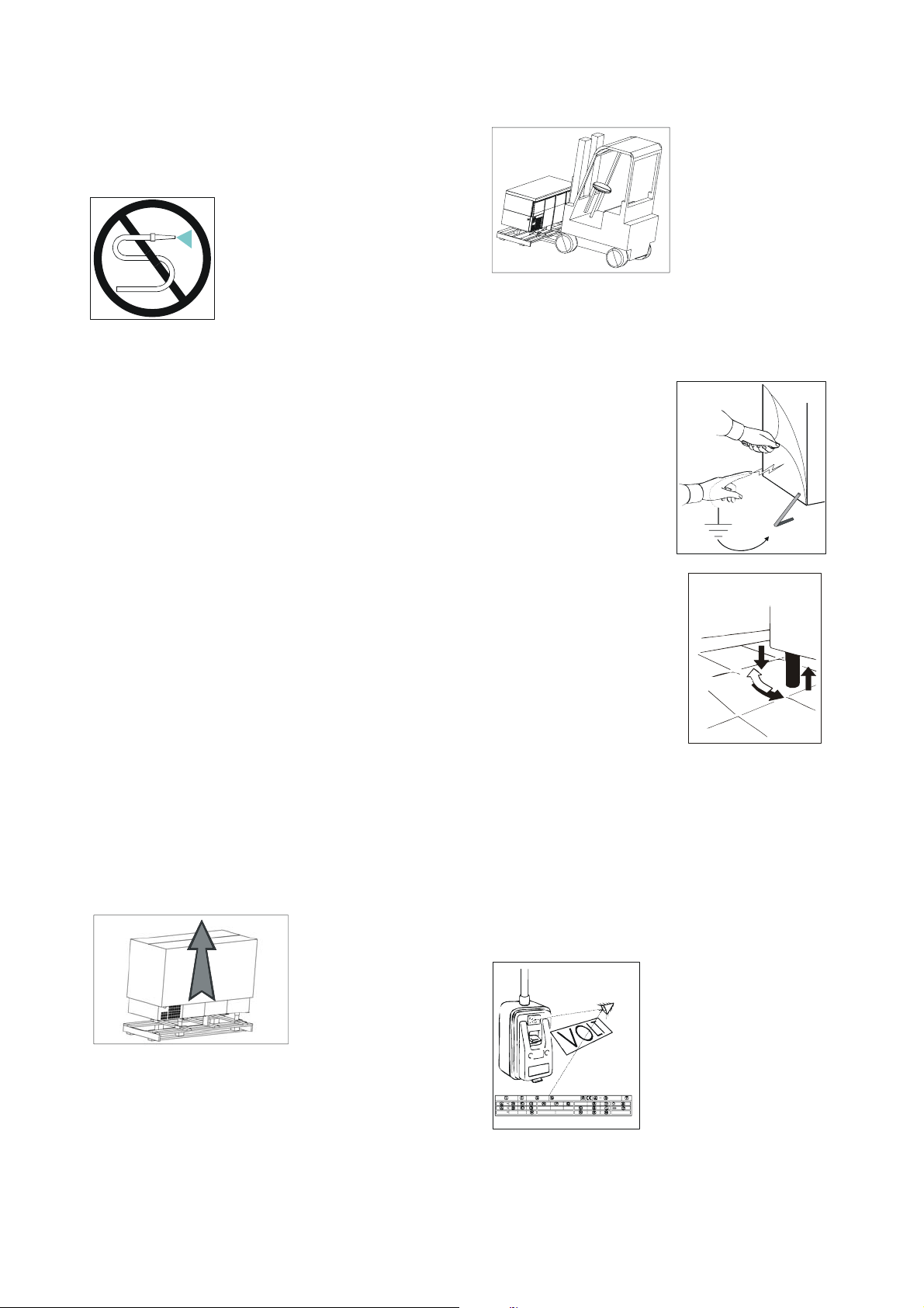
ACHTUNG: Stellen Sie keine warmen Speisen oder Getränke
in das Gerät ein.
ACHTUNG: Putzen Sie nicht in der Nähe der Kühltische bei
geöffneten Türen.
ACHTUNG: Verwenden Sie zur Reinigung des Gerätes oder
des Bodens in der Nähe desselben keine chlorhaltigen
(Chlorlaufe, Salzsäure usw.) oder giftigen Substanzen.
Die Reinigung und Wartung der Kühlanlage und des
Kompressorenbereiches darf ausschließlich von geschultem
und autorisiertem Personal durchgeführt werden.
Vor Durchführung von Wartungsmaßnahmen und bei
eventuellen Störungen ist das Gerät stromfrei zu machen.
Rufen Sie den Kundendienst eines autorisierten
Kundendienstzentrums an und verwenden Sie nur
Originalersatzteile. Bei Nichtbeachtung dieser Vorschriften
kann der sicherheitstechnische Zustand des Gerätes
beeinträchtigt werden.
Reinigen Sie das Gerät nicht mit
dem Wasserschlauch.
TECHNISCHE MERKMALE
Die technischen Merkmale sind auf einem dem Handbuch
beigelegten, gesonderten Blatt angegeben.
AUFSTELLUNG UND
INSTALLATION
Die Geräte werden stets auf Paletten mit einem
Schutzumkarton versehen versandt
Nach Empfangnahme und Auspacken sind bei Feststellung
eventueller Schäden oder fehlender Teile die im Kapitel
"ALLGEMEINE LIEFERHINWEISE" genannten Hinweise zu
befolgen
ACHTUNG: Die Inbetriebnahme und Installation des Gerätes
darf nur von geschultem Personal vorgenommen werden.
Achten Sie beim Entfernen Sie des Umkartons darauf, die
Oberflächen des Gerätes nicht zu beschädigen.
ACHTUNG: Verpackungsmaterialien (Plastikbeutel,
Styroporteile, Metallklammern usw.) müssen für Kinder
unzugänglich gelagert werden
Heben Sie das Gerät mit einem Hebewagen an und bringen
Sie es an den
vorgesehenen
Aufstellungsort. Achten Sie
darauf, daß der
Hebewagen nicht ungleich
belastet wird.
ACHTUNG: Sowohl bei
der Beförderung zum
Aufstellungsort als auch
beim späteren Umstellen
darf das Gerät nicht geschoben oder gezogen werden, da es
andernfalls umkippen und dabei beschädigt werden könnte
ACHTUNG: Stellen Sie das Gerät nicht in der Nähe von
Wärmequellen oder in sehr warmen Räumen auf, da sich die
Kühlleistung sonst vermindert und die Kühlanlage stark
belastet wird
Entfernen Sie die Schutzfolie
des Gerätes. Sie können
hierbei leichte elektrostatische
Schläge erhalten , die jedoch
nicht gefährlich sind. Zur
Verminderung dieses Effekts
genügt es, die Hand beim
Abziehen der Folie stets auf
dem Gerät oder aber die Folie
in Kontakt mit dem Boden zu
halten.
Stellen Sie nun die Füße so ein,
daß das Gerät korrekt
ausgerichtet ist.
Beim Ausrichten ist das Gerät
leicht nach hinten geneigt zu
halten, um ein besseres
Schließen der Türen zu
gewährleisten
Reinigen Sie das Gerät mit lauwarmem Wasser und
Neutralreiniger (siehe Kapitel "REINIGUNG") und installieren
Sie die eventuell vorhandenen Zubehörteile
Das Gerät ist mit einem SCHUKO-Stecker ausgestattet
Prüfen Sie, ob dieser der Richtlinie EN60320, EN60335-1 und
den länderspezifischen Richtlinien entspricht. Ersetzen Sie
den Stecker ggf. durch einen normgerechten Stecker.
ACHTUNG: Der Austausch des Steckers darf nur vom
Fachmann vorgenommen werden
Versichern Sie sich, daß die Versorgungsspannung den
Angaben auf dem Typenschild
entspricht.
ACHTUNG: Versichern Sie sich, daß die Netzsteckdose
geerdet ist. Sorgen Sie ggf. dafür, daß eine entsprechende
Erdung vorgenommen wird
6

Stecken Sie den Stecker in die Steckdose ein
A
Das Gerät ist nun betriebsbereit
Das Gerät muß in ein Äquipotentialsystem eingebaut werden,
dessen Leistung auf der Grundlage der
geltenden Normen überprüft werden
muß. Der Anschluß erfolgt mittels einer
im Kompressorbereich befindlichen
Schraube mit dem Aufdruck
"äquipotentiell".
SCHALTTAFELN
Alle Geräte der Produktpalette sind mit Schalttafeln
ausgestattet, die folgende Bedienelemente besitzen:
1) Gerätehauptschalter
2) Doppel t feuchtigkeit
3) Thermoregler
Betätigung der Tasten “
gleichzeitigem Drücken der
Temperatur geändert werden;
- Die Taste “
SETPOINT-Werte. Zum Schnelldurchlauf der Werte halten Sie
die Taste gedrückt;
- Die Taste “
SETPOINT-Werte. Zum Schnelldurchlauf der Werte halten Sie
die Taste gedrück;
- Lassen Sie nach erfolgter Änderung des Wertes die “
Taste wieder los. Auf dem Display wird daraufhin die im
Kühlschrank effektiv herrschende Temperatur angezeigt;
- Kontrollieren Sie nach einiger Zeit, ob die auf dem Display
des thermoregler (3) eingestellte Temperatur angezeigt wird.
Erst ab diesem Zeitpunkt dürfen Lebensmittels in das Gerät
eingelegt werden.
Es ist möglich den gewünschten Feuchtigkeitswert
entsprechend dem Nahrungsmittel, das man aufbewahren will
zu entscheiden.
Beim drücken der Taste (2) in Position “I“ erzielt man eine
Feuchtigkeit von 70%.
Beim drücken der Taste (2) in Position “II“ erzielt man eine
Feuchtigkeit von 90%.
” (Abb.e) dient zum Erhöhen der
” (Abb.f) dient zum Vermindern der
bb. d
”und “ ”, sowie
-Taste kann die eingestellte
” ;
1 2 3
EINSCHALTEN UND
INBETRIEBNAHME
Gehen Sie zum Einschalten des Gerätes wie folgt vor:
- der Stecker in die Steckdose einfügen. (50)
- Gehen Sie zum Einschalten des Gerätes wie folgt vor. (51)
- Stellen Sie den Netzschalter auf ON.
Betätigen Sie den Hauptschalter (1). Die Kontrolleuchte des
Schalters leuchtet auf.
Bringen Sie das Gerät mit Hilfe des thermoregler (3) auf die
gewünschte Betriebstemperatur. Beachten Sie hierbei
folgende Hinweise:
- Bei Drücken Sie der “
SETPOINT durch Blinken der ”
” Taste (Abb.d) wird der
”-LED angezeigt. Bei
Abb. e
Abb. f
7
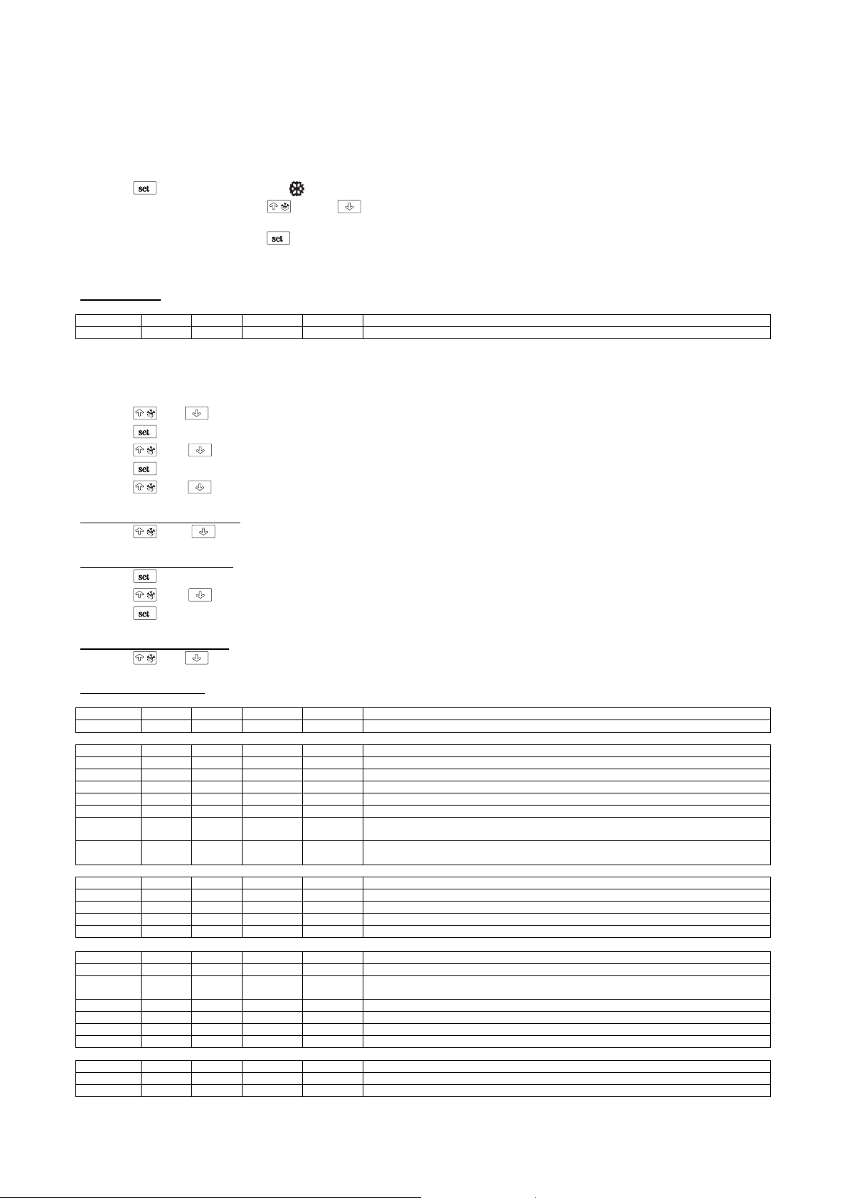
SOLLWERT UND KONFIGURATIONSPARAMETER
Einstellung des Betriebssollwerts
• sicherstellen, dass die Tastatur nicht blockiert ist und dass kein Prozessam laufen ist
• drücken, das LED blinkt
• beim Drücken der Tasten
ändern
• Nach der Änderung Taste
Den Betriebssollwert kann man auch über Parameter SP einstellen.
Betriebssollwert
LABEL MIN. MAS. EINHEIT DEF. BETRIEBSSOLLWERT
r1 r2 °C/°F (1) -2 Betriebssollwert
Einstellen der Konfigurationsparameter
Um die Prozedur aufzurufen:
• sicherstellen, dass kein Prozess am laufen ist
•
•
•
•
•
und 4 s lang drücken: das Display zeigt “PA” an
drücken
oder innerhalb 15 s drücken zum Einstellen von “-19”
drücken oder 15 s lang nichts betätigen
und 4 s lang drücken: zeigt das Display “SP” an.
Zum Wählen eines Parameters:
•
oder drücken.
Zum Ändern eines Parameter:
•
•
•
drücken
oder innerhalb von 15 s drücken
oder drücken 15 s nichts betätigen.
Zum Verlassen der Prozedur:
•
und 4 s lang drücken oder 60 s nichts betätigen.
Konfigurationsparameter
LABEL MIN. MAS. EINHEIT DEF. BETRIEBSSOLLWERT
SP r1 r2 °C/°F (1) -2 Betriebssollwert
LABEL MIN. MAS. EINHEIT DEF. MESSEINGÄNGE
CA1 -25 25 °C/°F (1) -0,5 Offset Zellensonde
CA2 -25 25 °C/°F (1) 0 Offset Verdampfersonde
P0 0 1 - 1 Sondentyp (0=PTC, 1=NTC)
P1 0 1 - 0 Dezimalpunkt Grad Celsius (für den während des Normalbetriebs angezeigten Wert) (1= JA)
P2 0 1 - 0 Maßeinheit Temperatur (2) (0=°C, 1=°F)
P3 0 2 - 1
P5 0 4 - 0
LABEL MIN. MAS. EINHEIT DEF. HAUPTREGLER
r0 0.1 15 °C/°F (1) 3,5 Differentialbetriebssollwert
r1 -99 r2 °C/°F (1) -2 Mindestbetriebssollwert
r2 r1 99 °C/°F (1) 8 Maximalbetriebssollwert
r3 0 1 - 0 Blockierung der Änderung des Betriebssollwerts (1= JA)
LABEL MIN. MAS. EINHEIT DEF. SCHUTZVORRICHTUNGEN DES VERDICHTERS
C0 0 240 min 0 Verzögerung Verdichter nach Einschalten des Geräts
C1 0 240 min 5
C2 0 240 min 3 Mindestdauer des Abschaltens des Verdichters
C3 0 240 s 10 Mindestdauer des Einschaltens des Verdichters
C4 0 240 min 10 Abschaltdauer des Verdichters während Fehler Zellensonde; siehe auch C5
C5 0 240 min 10 Einschaltdauer des Verdichters währen Fehler Zellensonde; siehe auch C4
LABEL MIN. MAS. U.M. DEF. ABTAUVORGANG
d0 0 99 h 6 Abtauintervall; siehe auch d8 (6) 0=Intervallabtauvorgang wird nie aktiviert
d1 0 1 - 0 Abtautyp (0= elektrisch, 1= Heissgas)
o oder binnen 15 Sekunden wird es möglich sein den eingestellten Temperaturwert zu
zur Bestätigung drücken oder andernfalls, während 15 Sekunden nicht operieren.
Funktion der Verdampfersonde 0= Sonde fehlt 1= Abtausonde und Thermostiersonde des
Verdampferventilators 2= Thermostiersonde des Verdampferventilators
während des Normalbetriebs angezeigte Größe 0= Zellentemperatur 1= Betriebssollwert
2= Verdampfertemperatur 3= “Zellentemperatur - Verdampfertemperatur”
Mindestzeit zwischen zwei aufeinanderfolgenden Einschaltvorgängen des Verdichters;
auch Verzöge rung Verdichter nach Ende Fehler Zellensonde (3)
8
d2 -99 99 °C/°F (1) 8 Temperatur bei Abtauende (nur wenn P3 = 1)
d3 0 99 min 30
d4 0 1 - 0 Abtauvorgang bei Einschalten des Geräts (1 = JA)
d5 0 99 min 0 Verzögerung Abtauvorgang beim Einschalten des Geräts (nur wenn d4 = 1)
d6 0 1 - 1
d7 0 15 min 3 Abtropfdauer
d8 0 2 _ 0
d9 -99 99 °C/°F (1) 0
dA 0 99 min 0
LABEL MIN. MAS. U.M. DEF. TEMPERATURALARME
A0 0 2 - 0
A1 -99 99 °C/°F (1) -2
A2 0 2 - 1
A4 -99 99 °C/°F (1) 15
A5 0 2 - 1
A6 0 240 min 120 Verzögerung Maximaltemperaturalarm nach Einschalten des Geräts (nur wenn A3 = 0)
A7 0 240 min 15 Verzögerung Temperaturalarm
A8 0 240 min 60
LABEL MIN. MAS. U.M. DEF. VERDAMPFERVENTILATOR
F0 0 4 - 1
F1 -99 99 °C/°F (1) -1
F2 0 2 - 0
F3 0 15 min 3 Dauer des Stillstands des Verdampferventilators
LABEL MIN. MAS. U.M. DEF. SERIELLES NETZ (MODBUS)
LA 1 247 - 1 Adresse Gerät
Lb 0 3 - 2
LP 0 2 - 2
(1) die Maßeinheit hängt von Parameter P2 ab
(2) Parameter für Regler entsprechend einstellen nach der Änderung des Parameters P2
(3) wenn der Parameter C1 auf 0 eingestellt ist, beträgt die Verzögerung nach dem Ende des Fehlers Zellensonde jedenfalls 2 min
(4) Differentialwert des Parameters ist 2,0 °C/4 °F
(6) das Gerät speichert die Zählung des Abtauintervalls alle 30 min.; die Änderung des Parameters d0 hat eine Wirkung nach dem Ende
desvorangehenden Abtauvorgangs oder der Aktivierung eines manuellen Abtauvorgangs
(7) das Display stellt den Normalbetrieb wieder her, wenn nach dem Ende des Stillstands des Verdampferventilators die Zellentemperatur unterden Wert
sinkt, an den das Display blockiert wurde (oder wenn ein Temperaturalarm auftritt)
(8) wenn der Parameter P3 auf 0 oder 2 eingestellt ist, funktioniert das Gerät, als ob der Parameter d8 auf 0 eingestellt wäre
(9) wenn bei Aktivierung des Abtauvorgangs die Einschaltdauer des Verdichters kleiner als die mit Parameter dA eingestellte Zeit ist, bleibt derVerdichter
zusätzlich für die zu dessen Abschluss notwendigen Zeit eingeschaltet
(10) wenn der Parameter P3 auf 0 eingestellt ist, funktioniert das Gerät, als ob der Parameter A0 auf 0 eingestellt wäre
(12) während des Abtauvorgangs, des Abtropfens und des Ventilatorstillstands fehlen die Temperaturalarme, es sei denn diese traten nach derAktivierung
des Abtauvorgangs auf
(14) wenn der Parameter P3 auf 0 eingestellt ist, funktioniert das Gerät, als ob der Parameter F0 auf 2 eingestellt wäre
Abtaudauer wenn P3 = 0 oder 2; Maximalabtaudauer wenn P3 = 1 (0= Abtauvorgang
wird beim Einschalten des Geräts nie aktiviert)
Während des Abtauvorgangs angezeigte Temperatur 0= Temperatur der Zelle 1= wenn
bei Aktivierung des Abtauvorgangs die Temperatur der Zelle unter dem “Betriebssollwert
+r0”, am maximalen “Betriebssollwert + r0” liegt; wenn bei Aktivierung des Abtauvorgangs
dieTemperatur der Zelle über dem “Betriebssollwert + r0”, bei Maximaltemperatur der
Zelle bei Aktivierung des Abtauvorgangs liegt (7)
Typ des Abtauintervalls
0= das Abtauen wird aktiviert, wenn das Gerät über die Zeit d0 eingeschaltet war
1= das Abtauen wird aktiviert, wenn der Verdichter über die Zeit d0 eingeschaltet war
2= das Abtauen wird aktiviert, wenn die Temperatur des Verdampfers über die Zeit d0 (8)
unterhalb der Temperatur d9 war
Verdampfertemperatur über dem Wert, bei dem das Zählen des Abtauintervalls
unterbrochen wird (nur wenn d8 = 2)
Mindestdauer des Einschaltens des Verdichters bei Aktivierung des Abtauvorgangs, damit
dieser aktiviert wird (nur wenn d1 = 1) (9)
Temperaturwert, der dem Mindesttemperaturalarm zugeordnet ist 0= Temperatur der
Zelle 1= Temperatur des Verdampfers (10)
Temperaturwert, unter dem der Alarm Mindesttemperatur aktiviert wird; siehe auch A0
und A2 (4)
Alarmtyp Mindesttemperatur 0= Alarm fehlt 1= bezüglich Betriebssollwert (d.h.
“Betriebssollwert - A1”; berücksichtige A1 ohne Zeichen) 2= absolut (d.h. A1)
Temperaturwert, über dem der Maximaltemperaturalarm aktiviert wird; siehe auch A3 und
A5 (4)
Alarmtyp Maximaltemperatur
0= Alarm fehlt
1= bezüglich Betriebssollwert (d.h. “Betriebssollwert + A4”; berücksichtige A4 ohne
Zeichen)
2= absolut (d.h. A4)
Verzögerung Maximaltemperaturalarm nach Ende Stillstand Verdampferventilator (nur
wenn A3 = 0)(12)
Aktivität des Verdampfers während Normalbetrieb
0= abgeschaltet
1= eingeschaltet
2= parallel zum Verdichter
3= abhängig von F1 (14)
4= abgeschaltet, wenn der Verdichter abgeschaltet ist, abhängig von F1 wenn Verdichter
eingeschal-tet ist (14)
Verdampfertemperatur über der Verdampferventilator abgeschaltet wird (nur wenn F0 = 3
oder 4) (4)
Aktivität des Verdampferventilators während des Abtauens und Abtropfens
0= abgeschaltet
1= eingeschaltet
2= abhängig von F0
Baudrate
0=2.400 baud
1=4.800 baud
2=9.600 baud
3=19.200 baud
Parität
0=keine Parität
1=ungleich
2=gleich
9
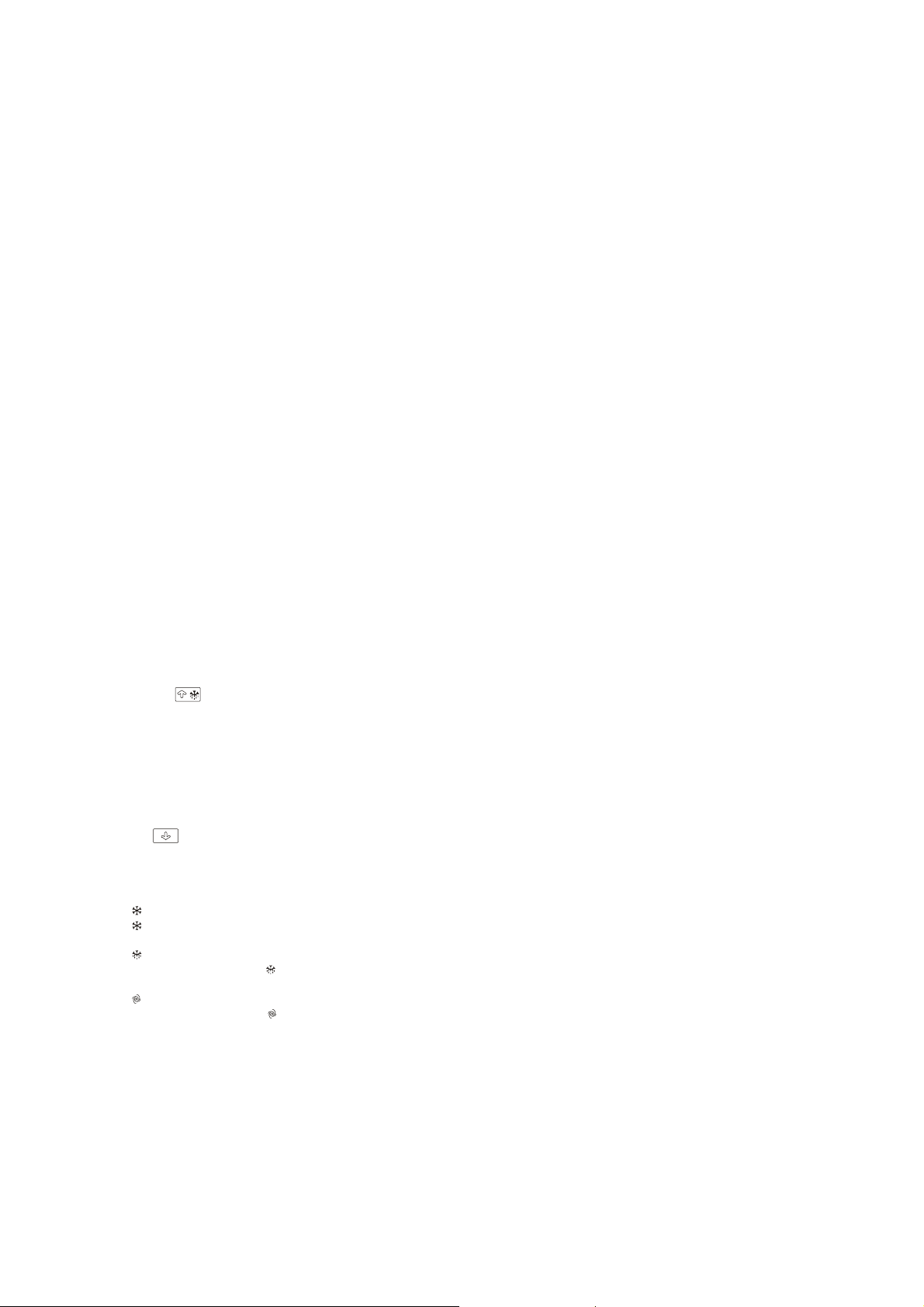
BESCHICKUNG DES
PRODUKTES
• Produkt gleichmäßig in den Kühlraum verteilen, damit
eine gute Belüftung gestattet wird;
• Vermeiden Sie die Belüftungszonen der an der linken
Raumseite angelegten Kühlanlage abzudecken;
• Vermeiden Sie die Lebensmittel, die eine niedrige
Konservierungstemperatur benötigen, ins letzte Kühlfach
unten rechts einzuordnen;
• Lebensmittel bei der Beladung möglichst mit geeigneten
Schutzkunststofffolien verpackt und abgedeckt in den
Kühlraum einordnen;
• Keine zu warmen Speisen oder Getränke ins Gerät
einführen;
• Bei der Beladung oder Entladung der Lebensmittel
Gerätetüren so kurz wie möglich offen lassen.
STILLSETZEN
Das Gerät kann jederzeit ausgeschaltet werden. Stellen Sie
hierzu den Hauptschalter auf OFF; woraufhin die Kontrollampe
des Schalters erlischt
ABTAUEN
Die Entfrostung der Apparate ist völlig automatisch und erfolgt
durch geeigneten elektrischen Widerstand.
Der Abtauvorgang wird durch das thermoregler reguliert.
Die Entfrostung findet alle 6 Betriebsstunde. Die Daurer der
Entfrostung wird vom Kühlschrank reguliert.
Unabhängig davon kann jederzeit ein manueller Abtauzyklus
zwischengeschaltet werden. Drücken Sie dazu 5 Sekunden
lang die Taste “
Nach dem manuellen Abtauvorgang stellt sich das Gerät
wieder auf automatisches Abtauen ein.
Der Apparat ist mit automatischer Kondensverdampfung
ausgestattet.
ALARME
Der Knopf “ ”schaltet die folgende Alarme.
Auf dem display werden folgende Alarme und Signalisierungen
sichtbar gemacht:
Led “
Led “
Kompressoraktivierung.
Led “
Der aufleuchtende Ledanzeiger “
Aktivierungsverspätung einer Entfrostung oder einen Abtropfenverlauf.
Led “
Aufleuchtender Ledanzeiger “
Verdampferentlüfters.
"EO" blinkend auf dem Display zeigt eine der folgenden
Anomlaien an: fehlerhafter Zellensondentyp,
Defekt der Zellensonde oder der Anschlüsse, außer
Grenzmasse gemessene Temperatur.
"E1" blinkend auf dem Display zeigt eine der folgenden
Anomalien an: fehlerhafter Verdampfersondentyp,
Defekt der Verdampfersonde oder Anschlüsse, außer
Grenzmasse gemessene Temperatur.
"E2" blinkend auf dem Display: Entstellung der Gestaltdaten
im Speicher; versuchen Sie den Apparat auszuschalten und
”eingeschaltet zeigt die Kompressoraktivierung.
”blinkend zeigt die Verspätung der
”eingeschaltet zeigt die laufende Enteisung.
” eingeschaltet zeigt die laufende Ventilatorzelle.
” (siehe Abb.e).
”zeigt die
” zeigt eine Stillsetzung des
wieder einschalten; falls das Alarmsignal nicht verschwindet,
den Wärmeregler ersetzen.
Zellentemperatur: Richtiger oder blinkender Wert auf dem
Display, die aus der Sonde gemessene Temperatur ausser
den vorbestimmten Grenzen.
BETRIEBSSTÖRUNGEN
Bei eventuell auftretenden Betriebsstörungen sollten Sie sich
vor Anrufen des Kundendienstes versichern, daß:
• Die Kontrollampe des Hauptschalters leuchtet und
Netzspannung anliegt
• Die eingestellte Temperatur dem gewünschten Wert
entspricht
• Die Türen richtig geschlossen sind
• Das Gerät nicht in der Nähe von Wärmequellen aufgestellt
ist
• Der Kondensator sauber ist und der Ventilator einwandfrei
funktioniert
• Der Verdampfer nicht übermäßig vereist ist
Wenn nach Durchführung dieser Kontrollen die
Betriebsstörungen nicht beseitigt sind, wenden Sie sich an
Ihren örtlichen Kundendienst. Geben Sie dabei das Modell und
die auf dem Typenschild (Geräterückseite) befindliche
Typennummer an.
TÄGLICHE
REINIGUNGSMASSNAHMEN
Damit eine perfekte Hygiene und eine Erhaltung des Gerätes
garantiert wird, sollten die folgenden Reinigungsverfahren
ordentlich und/oder täglich durchgeführt werden:
1. Die Außenflächen des Apparates gründlich mit einem ins
Wasser eingetauchten, sanften und ausgewringten
Schwamm und säurefreien Reiniger putzen, und dies nur
der Richtung des Satinierens nach indem besonders auf
die Reinigung der Arbeitsfläche, der Türen und der
Schubladen in der Handgriffzone geachtet wird.
• Das Reinigungsmittel darf kein Chlor enthalten und soll
nicht abrasiv sein.
• Folgende Reinigungsmittel werden empfohlen:
- Desinfektionsreiniger mit kombinierter Wirkung
(die, nicht ionische grenzflächenaktive Stoffe, Chloridbenzal,
Chelatsubstanzen und PH Puffer, enthalten)
- säurefreie Laborreiniger , für manuelles Abwaschen
(die, anionische und nicht ionische grenzflächenaktive
Stoffe, enthalten)
- Entfettungsmittel fürs Nahrungsmilieu
(die, anionische grenzflächenaktive Stoffe und EDTA,
enthalten)
• Vor dem Gebrauch die Reinigungsmittel eventuell gemäß
der auf das Etikett aufgetragenen Vorschriften
verdünnen.
• Die Reinigungsmittel mindestens 5 minutenlang
einwirken lassen.
• Die Gerätes mehrmals mit einem Schwamm und
fließendem Wasser abspülen.
• Mit einem sauberen Schwamm sorgfältig abtrocknen.
ACHTUNG: absolut keine Werkzeuge die zerkratzen können
mit herrührende Rostbildung, gebrauchen.

FLECKEN UND
ANGETROCKNETE SPEISERESTE
Falls im Gerätes Nahrungsflecken oder –reste anwesend sind,
diese mit Wasser abwaschen und dann entfernen bevor sie
härten.
Wenn die Reste schon gehärtet sind, wie folgt verfahren:
1. Einen ins lauwarme Wasser eingetauchten sanften
Schwamm und säurefreien Reiniger benutzen (man kann
diejenigen gebrauchen, die für das tägliche Putzen
vorgesehen sind und zwar mit der höchsten
Konzentration unter denen, die auf das Etikett
vorgesehen sind).
2. Den gehärteten Rückstand anfeuchten, indem man zirka
alle 5 Minuten mit dem ins
Wasser eingetauchten Schwamm und Reinigungsmittel
über den gehärteten Schmutz wischt, um diesen somit
wenigstens 30 minutenlang feucht zu halten.
3. Am Ende des Einweichens den Rückstand mit dem ins
Wasser eingetauchten Schwamm und säurefreien
Reinigungsmittel entfernen.
4. Wenn nötig, eine Holzspachtel oder eine rostfreie
Stahllanzette benutzen und darauf achten, dass die
Kühlschrankoberflächen nicht beschädigt werden.
5. Am Endpunkt des Verfahrens sollte ein täglicher
Reinigungskreislauf aller Innenflächen des Gerätes
getätigt werden.
6. Am Ende der Reinigung mehrmals mit einem Schwamm
und fließendem Wasser abspülen.
7. Mit einem sauberen Schwamm gründlich abtrocknen.
Auch der Boden unter und herum den Schrank muss sauber
und in vollkommene Hygiene gehalten sein.
Mit Wasser und Seife oder neutralen Reinigungsmittel
waschen.
Die Bleche mit Silikonwachs schützen.
ALLGEMEINE REINIGUNGSUND WARTUNGSMASSNAHMEN
Zur Erhaltung der Leistungsfähigkeit des Gerätes sind die
nachstehend aufgeführten Reinigungs- und
Wartungsmaßnahmen mehrmals im Jahr vorzunehmen
Vor Durchführung dieser Maßnahmen ist folgendes zu tun:
• Stellen Sie den Schalter auf der Schalttafel auf OFF
• Stellen Sie den Netzschalter auf OFF
• Ziehen Sie den Netzstecker und warten Sie, bis das
Gerät vollständig abgetaut ist
• Reinigen Sie die Kühlgruppe und insbesondere die
gerippte Batterie mit einem Staubsauger, einer Bürste
oder einer Bürste (keine Metallbürste!)
ACHTUNG: Die Reinigung und Wartung der Kühlgruppe und
des Kompressorbereiches darf nur von einem autorisierten
Fachmann vorgenommen werden. Ungeschulten Personen ist
jeder diesbezügliche Eingriff untersagt.
Die Außen- und Innenflächen des Apparates nach den im
Alltagsreinigungsabschnitt angegebenen Hinweisen putzen.
Anschließend mit klarem Wasser sorgfältig nachspülen und
trocknen.
ACHTUNG: Wie bereits eingangs erläutert, darf das Gerät
keinesfalls mit dem Wasserschlauch gereinigt werden
Die allgemeinen Reinigungs- und Wartungsmaßnahmen sind
damit abgeschlossen.
AUFBEWAHREN BEI LÄNGERER
NICHTBENUTZUNG
Wenn Sie das Gerät für längere Zeit nicht benutzen wollen,
beachten Sie bitte folgende Empfehlungen:
• Stellen Sie den Schalter auf der Schalttafel auf OFF
• Stellen Sie den Netzschalter auf OFF
• Ziehen Sie den Netzstecker und warten Sie, bis das
Gerät vollkommen abgetaut ist
• Räumen Sie den Kühltisch aus und reinigen Sie ihn
gemäß den Angaben im Kapitel "REINIGUNG"
• Zur Vermeidung von Geruchsbildung sollten Sie die
Türen und Schubladen des Gerätes ein wenig offen
lassen
NÜTZLICHE HINWEISE ZUR
PFLEGE UND WARTUNG VON
EDELSTAHL
Die Außenflächen der Kühltische bestehen aus Edelstahl des
Typs AISI 304 18/10
Zur Reinigung und Wartung dieser Teile aus rostfreiem
Edelstahl sollten Sie die entsprechenden Hinweise beachten
und daran denken, daß es vorrangiges Gebot ist, die
Lebensmittel keinerlei Giftbelastung auszusetzen und eine
hygienische Lagerung zu gewährleisten
Rostfreier Stahl besitzt eine dünne Oxidschicht zur
Vermeidung von Rostbildung. Bestimmte Substanzen und
Reinigungsmittel können diese Schutzschicht zerstören oder
zumindest angreifen und dadurch zur Rostbildung beitragen.
Informieren Sie sich vor Gebrauch von Reinigungsmitteln bei
Ihrem Händler über deren Eigenschaften
Falls Sie Kratzer auf der Oberfläche entfernen wollen, können
Sie hierzu Stahlwolle aus EDELSTAHL oder
Scheuerschwämme aus Synthetikfasern benutzen. Folgen Sie
dabei der Satinierungsrichtung
ACHTUNG: Verwenden Sie zur Reinigung von EDELSTAHL
keinesfalls Eisenwolle und lassen Sie diese auch nicht auf der
Oberfläche der Kühltische liegen. Die darauf verbleibenden
Eisenrückstände könnten zur Flugrostbildung führen und den
Hygienezustand beeinträchtigen
ENTSORGUNG
MÜLLENTSORGUNG
Bei Ende des Lebenszyklus des Produktes, Apparat nicht in
die Umwelt freisetzen. Die Türen müssen vor der Entsorgung
des Gerätes demontiert werden.
Eine provisorische Lagerung des Mülls ist Hinblick auf eine
Entsorgung mittels definitiver Behandlung und/oder Lagerung
zulässing.
Trotzdem sind die im Land des Betreibers geltenden
Gesetzgebungen des Umweltschutzes zu beachten.
11

VERFAHRENSWEISE HINSICHTLICH DER GROBEN
DEMONTAGE DES GERÄTES
In verschiedenen Ländern gelten unterschiedliche
Gesetzgebungen, daher sind die Vorschriften der
Gesetzgebung und der Behörden des Landes zu beachten, in
dem die Demolierung erfolgt.
Im allgemeinen ist der Kühlschrank an spezielle Sammel-und
Zerlegungszentren abzugeben. Den Kühlschrank demontieren,
indem die Bestandteile je nach ihrer chemischen
Zusammensetzung zusammenzufassen sind, wobei darauf zu
achten ist, daß sich in dem Kompressor Schmieröl und
Kühlflüssigkeit befinden, die aufgefangen werden und
wiederverwertbar sind, und daß es sich be den Bestandteilen
des Kühlschranks um Sondermüll handelt, der von den
städtischen Behörden zu entsorgen ist.
Das Gerät ist vor der Entsorgung unbrauchbar zu machen,
indem das Stromkabel und jegliche Schließvorrichtung entfernt
werden, um zu vermeiden, daß jemand in seinem Inneren
eingeschlossen werden kann.
DIE DEMONTIERARBEITEN SIND AUF JEDEN FALL VON
QUALIFIZIERTEM FACHPERSONAL DURCHZUFÜHREN.
SICHERHEIT BEI DER ENTSORGUNG VON ELEKTROUND ELEKTRONIK-ALTGERÄTEN (WEEE-RICHTLINIE
2002/96/EG)
Umweltschädliche Stoffe dürfen nicht in die Umwelt
gelangen. Die Entsorgung in Einklang mit den geltenden
gesetzlichen Bestimmungen vornehmen.
Gemäß der WEEE-Richtlinie 2002/96/EG (Elektro- und Elektronik-Altgeräte) muss der Betreiber bei der endgültigen
Außerbetriebnahme die Geräte bei den hierfür vorgesehenen
Rücknahmestellen abgeben oder im Moment des Erwerbs
neuer Geräte unzerlegt an den Verkäufer zurückgeben.
Alle Geräte, die in Einklang mit der WEEE-Richtlinie 2002/96/
EG entsorgt werden müssen, müssen mit dem
entsprechenden Symbol gekennzeichnet sein
Die gesetzwidrige Beseitigung von Elektro- und Elektronik-Altgeräten zieht Sanktionen nach Maßgabe der
gesetzlichen Bestimmungen in dem Mitgliedstaat nach
sich, in dem die Zuwiderhandlung begangen wurde.
Elektro- und Elektronik-Altgeräte können gefährliche Stoffe
enthalten, die schädlich für die Gesundheit der Personen und
für die Umwelt sein können. Daher müssen sie unbedingt
vorschriftsmäßig entsorgt werden.
.
TECHNISCHES DATENBLATT
FÜR KÜHLMITTEL
1) R404a: Bestandteile der Flüssigkeit
• Trifluoräthan (HFC 143a) 52%
• Pentafluoräthan (HFC 125) 44%
• Tetrafluoräthan (HFC 134a) 4%
GWP = 3750
ODP = 0
2) Gefahrenkennzeichnung
Bei längerem Einatmen kann eine Betäubungswirkung
eintreten. Bei sehr lagen Einatmungszeiten kann es zu
Herzrtythmusstörungen und plötzlichem Tod kommen. Beim
Versprühen oder Verspritzen des Produkts können Haut-oder
Augenschaden durch Erfrierung auftreten.
3) Erste-Hilfe-Maßnahmen
• Einatmen:
verletzten aus der Gefahrenzone entfernen, zudecken und
ruhigstellen. Falls erforderlich, mit Sauerstoff beatmen. Bei
eingetretenem oder bei Anzeichen eines nahenden
Atemstillstands ist der Verletzte kunstlich zu beatmen. Bei
Herzversagen ist eine äußerliche Herzmassage
durchzuführen. Sofort Arzt rufen.
• Hautkontakt:
Die betroffene Hautstelle mit Wasser erwärmen. Die mit
Kühlmittel in Berührung geratenen Kleidungsstücke ausziehen.
ACHTUNG: Bei Erfrierungen können die Kleidungsstücke an
der Haut kleben.
Bei Hautkontakt sofort mit reichlich warmem Wasser abspülen.
Bei Auftreten von Symptomen wie Hautreizungen oder
Blasenbildung ist der Arzt zu rufen.
• Augenkontakt:
Auge sofort mit speziellen Augenbadiosungen oder frischem
Wasser ausspülen. Dabei Augenlider aufspreizen und
mindestens 10 Minuten spülen. Arzt rufen.
• Verschlucken:
kann das Brechen verursachen. Wenn der Verletzte bei
Bewußtsein ist, Mund mit Wasser ausspülen und 200-300 ml
Wasser trinken lassen. Sofort Arzt rufen.
• Weitere Behandlung:
Falls erforderlich, symptomische Behandlung und
Unterstützungstherapie vornehmen. Kein Adrenalin oder
ähnliche Sympatikomimetika verabreichen, da Gefahr von
Herzarythmie mit möglichem Herzstillstand besteht.
4) Umweltschutzinformationen
Beständigkeit und Abbaubarkeit
• HFC 143a:
Baut sich langsam in der unteren Atmosphäre (Troposphäre)
ab. Die Dauer in der Atmosphäre beträgt 65 Jahre.
• HFC 125:
Baut sich langsam in der unteren Atmosphäre (Troposphäre)
ab. Die Dauer in der Atmosphäre beträgt 40 Jahre.
• HFC 134a:
Baut sich relativ schnell in der unteren Atmosphäre
(Troposphäre) ab. Die Dauer in der Atmosphäre beträgt 15,6
Jahre.
• HFC 143a, 125, 134a:
Keine Auswirkung auf die photochemische Verschmutzung
(fällt nicht unter flüchtige organische Stoffe – VOC – gemäß
UNECE-Vereinbarung).
Verursacht keine Schäden in der Ozonschicht.
Die in die Atmosphare gelangenden Abfallprodukte
verursachen keine Langzeitverseuchung der Gewässer.
Elektroschaltbild siehe letzte Seite des Handbuches.
POS: BESCHREIBUNG
1 KOMPRESSOR
2 KONDENSATOR
3 KLEMMENBRETT
6 HAUPTSCHALTER
8 STECKER
9 VERDAMPFERVENTILATOR
14 FENCHTIGKEITREGLER MIT LEUCHTE
21 WIDERSTAND ENTFROSTUNG
44 RELAY
69 ERDUNGSKLEMME
90 DIGITALER THERMOREGLER
102 SICHERHEITSTHERMOSTAT
12


INDEX
DESCRIPTION DE L'APPAREIL 5
PLAQUETTE SIGNALETIQUE 5
NOTES GENERALES A LA LIVRAISON 5
PRESCRIPTIONS DE SECURITE 5
CARACTERISTIQUES TECHNIQUES 6
MISE EN ŒUVRE ET INSTALLATION 6
TABLEAUX DE COMMANDE 7
DEMARRAGE ET FONCTIONNEMENT 7
POINT DE CONSIGNE ET PARAMETRES DE CONFIGURATION 8
CHARGEMENT DU PRODUIT 10
ARRET 10
DEGIVRAGE 10
ALARMS 10
IRREGULARITES DE FONCTIONNEMENT 10
NETTOYAGE QUOTIDIEN 10
TACHES D'ALIMENTS ET RESIDUS RACCORNIS 11
NETTOYAGE ET ENTRETIEN GENERAL 11
INTERRUPTIONS D'USAGE 11
CONSEILS UTILES POUR L'ENTRETIEN DE L'ACIER INOXYDABLE 11
MISE AU REBUT 11
FICHE TECHNIQUE DU REFRIGERANT 12
4
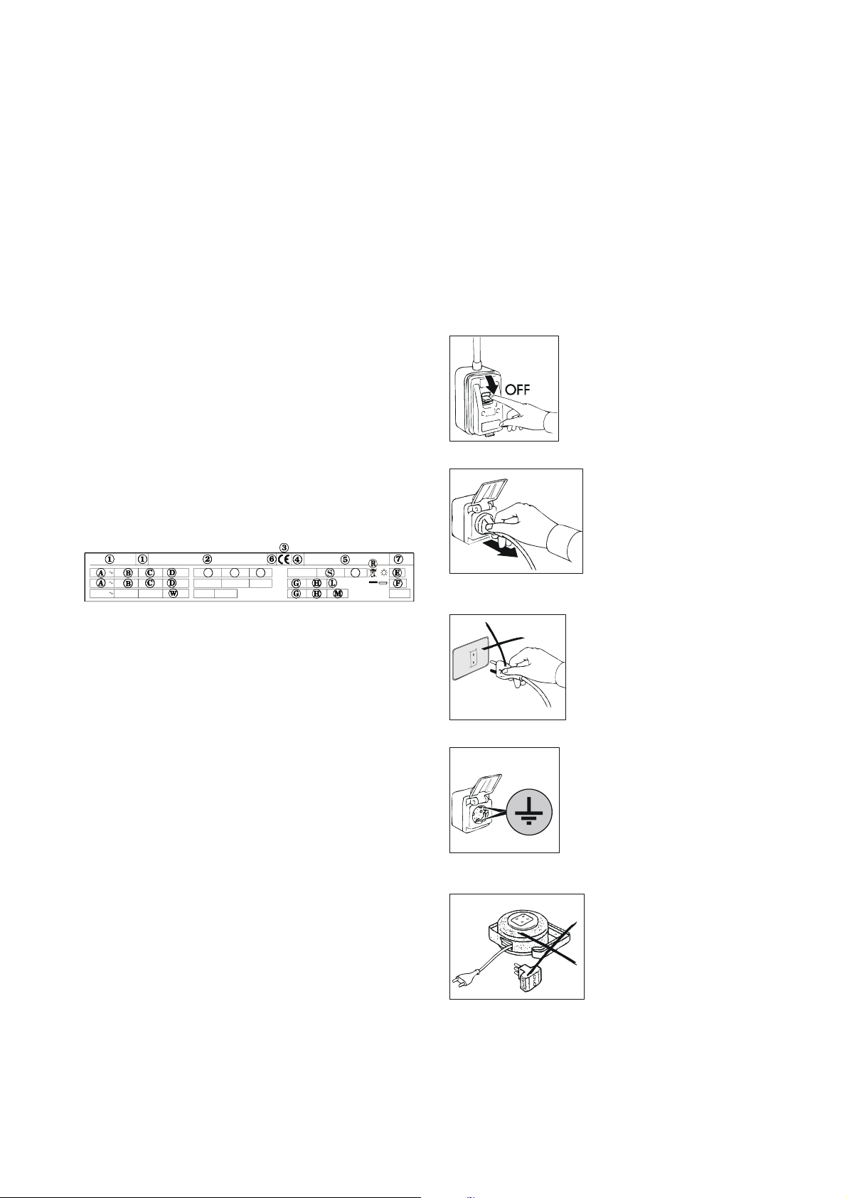
DESCRIPTION DE L'APPAREIL
Cet appareil a été conçu pour la réfrigération et la
conservation de denrées. Toute autre utilisation est considèrée
comme étant impropre.
ATTENTION : les appareils ne sont pas prévus pour être
installés à l’extérieur et/ou en endroits soumis à l’action
d’agents atmosphériques.
Le fabricant décline toute responsabilité en cas
d’utilisations non consenties de l’appareil.
Les comptoirs sont dotés sur leur partie supérieure d'un plan
de travail que l'on peut réaliser sur demande avec rehausse;
de même, des comptoirs sans plan de travail, mais avec de
similaires capacités réfrigérantes sont disponibles.
Les commandes sont à thermorégulateur digital et
interrupteur général.
Le groupe du moteur est logé sur la gauche du comptoir, dans
un emplacement prévu à cet effet.
L'évaporateur est situé à l'interne de l'emplacement du moteur,
un pour chaque emplacement, et il est protégé par des tôles
prévues.
La ventilation interne s'effectue à l'aide de ventilateurs
tangentiels protégés et situés au-dessus de l'évaporateur.
L’appareil est doté d’évaporation automatique de la
condensation.
PLAQUETTE SIGNALETIQUE
La plaquette signalétique est positionnée sur l'appareil; elle
fournit une série d'indications importantes sur les
caractéristiques techniques et constructives du produit.
Tout en vous félicitant pour votre excellent choix, nous
espérons que vous tirerez le meilleur profit de nos comptoirs
réfrigérés en suivant les indications et les précautions
nécessaires listées dans ce Mode d'emploi.
Toute reproduction du Mode d'emploi est interdite. Les
caractéristiques, suite à la constante recherche de l'innovation
et de l'amélioration des qualités technologiques, peuvent subir
des modifications sans préavis.
PRESCRIPTIONS DE SECURITE
ATTENTION: avant d'effectuer toute opération d'entretien ou
de nettoyage, isoler l'appareil de toute source d'énergie
électrique
Positionner l'interrupteur général sur OFF.
ENLEVER LA FICHE.
TQPN
DETAIL DE LA PLAQUETTE SIGNALETIQUE
1) modèle
2) fabricant
3) symbole marquage CE
4) année de construction
5) n° d'immatriculation
6) classe d'isolement électrique
7) classe de protection électrique
A) tension d'alimentation électrique
B) intensité de courant électrique
C) fréquence nominale
D) puissance nominale
E) puissance nominale éclairage
F) courant fusible
G) type gaz réfrigérant
H) quantité de gaz réfrigérant
L) classe de température installation frigorifique
M) pression max. d'alimentation
N) débit ventilateur
P) vitesse de rotation du ventilateur
Q) hauteur d'élévation ventilateur
R) symbole DEEE
S) débit vapeur
T) pression vapeur
W) puissance éléments réchauffants
Pour toute communication avec le Fabricant, il faut toujours
citer le NUMERO D'IMMATRICULATION de l'appareil.
NOTES GENERALES A LA
LIVRAISON
Lors de la livraison, vérifier l'intégrité du conditionnement et
qu'aucun dommage n'a été provoqué par le transport.
Vérifier la correspondance des caractéristiques du produit
avec les spécifications de la commande. Si des différences se
présentent, contacter immédiatement le revendeur.
ATTENTION: ne pas utiliser des prises ou des fiches
démunies de mise à la terre.
La prise secteur doit être dotée de MISE A LA TERRE.
ATTENTION: pour la connexion au secteur, ne jamais utiliser
des adaptateurs ou des rallonges.
ATTENTION: avant d'introduire les aliments à conserver,
attendre le délai nécessaire à l'obtention de la température
programmée.
Avant d'introduire les aliments dans les appareils, il faut
toujours les recouvrir des films alimentaires prévus à cet effet.
5

ATTENTION: ne jamais introduire dans les appareils des
boissons ou des aliments chauds.
ATTENTION: ne jamais effectuer le nettoyage des zones
voisines aux appareils si leurs portes sont ouvertes.
ATTENTION: ne jamais utiliser des substances à base de
chlore (eau de Javel, acide muriatique, etc…) ou toxiques pour
le nettoyage ou dans le voisinage des appareils.
Le nettoyage et l'entretien de l'installation de réfrigération et de
la zone des compresseurs nécessite l'intervention d'un
technicien qualifié et agréé; pour ces motifs, il ne peut
absolument pas être effectué par du personnel non spécialisé.
En cas d'interventions d'entretien ou d'anomalies de
fonctionnement, il faut déconnecter complètement l'appareil,
demander l'intervention du SERVICE D'ASSISTANCE à un
centre agréé et n'utiliser que des pièces de rechange
originales, si nécessaire. Le non-accomplissement de ces
opérations peut compromettre la sécurité des appareils.
Ne jamais laver les comptoirs avec
des jets d'eau directs ou à haute
pression.
CARACTERISTIQUES
TECHNIQUES
Les caractéristiques techniques sont listées dans la fiche
annexée au Mode d'emploi
MISE EN ŒUVRE ET
INSTALLATION
Les appareils sont toujours livrés sur palette et conditionnés
dans un carton de protection
Lors de la réception de la marchandise, après avoir déballé les
cartons, si l'on constate des dommages ou des éléments
manquants, procéder comme détaillé dans le chapitre "NOTES
GENERALES A LA LIVRAISON"
ATTENTION: les opérations de mise en œuvre et d'installation
doivent être effectuées par du personnel spécialisé.
Enlever la boite d'emballage en prenant soin à ne pas
endommager les surfaces de l'appareil.
ATTENTION: les éléments de l'emballage (sachets en
plastiques, polystyrène expansé, clous, etc…) doivent être
stockés hors portée des enfants car ce sont de potentielles
sources de danger
Avec un chariot à fourches, lever l'appareil et le transporter sur
le lieu de l'installation, en
prenant soin à bien
équilibrer le chargement.
ATTENTION: tant pour le placement sur le lieu d'installation,
que pour des déplacements futurs, ne jamais pousser ou
traîner l'appareil car ce dernier peut basculer et ont peut donc
provoquer des dommages à des parties mêmes de l'appareil
ATTENTION: ne jamais positionner l'appareil dans le
voisinage de sources de chaleur
ou dans des lieux ayant des
températures élevées; cette
situation peut provoquer une
mineure performance de
l'appareil et une excessive
sollicitation de l'installation de
réfrigération
Enlever la pellicule de protection
du produit. Cette opération peut
provoquer des petites
électrocutions fastidieuses qui ne sont toutefois pas
dangereuses (électricité statique). On élimine, ou réduit,
l'inconvénient en maintenant une main toujours posée sur
l'appareil ou en connectant à la terre l'emballage externe.
A ce point, on peut procéder au nivellement de l'appareil en
agissant sur les pieds.
Niveler l'appareil en le maintenant légèrement incliné vers
l'arrière afin de faciliter la fermeture optimale des portes
Nettoyer avec de l'eau tiède et du savon neutre (voir le
chapitre "NETTOYAGE") et installer les éventuels accessoires
L'appareil est doté de fiche électrique du type SHUCO
Vérifier sa conformité aux normes EN60320, EN60335-1 et
aux normes nationales. Si la fiche n'est pas conforme aux
normes, la remplacer par une adaptée.
ATTENTION: l'opération doit être effectuée par un technicien
spécialisé
Vérifier que la tension de secteur correspond à celle indiquée
sur la plaquette des
caractéristiques techniques de
l'appareil.
6
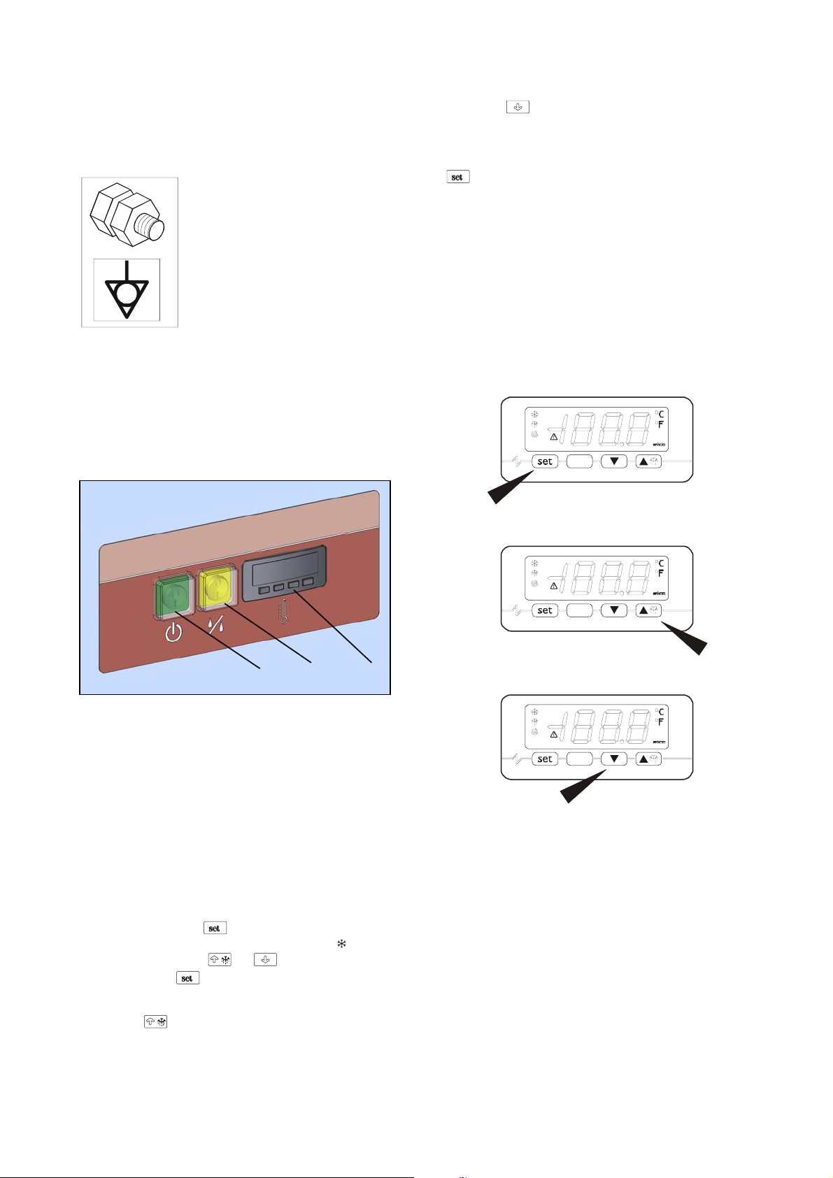
ATTENTION: vérifier que la prise secteur est prédisposée de
mise à la terre, sinon la modifier
Connecter la fiche à la prise secteur
Maintenant, les opérations de mise en œuvre sont terminées.
L'appareil doit être englobé dans un système équipotentiel
dont l'efficacité doit être vérifiée
conformément à la normalisation en
vigueur. On effectue la connexion par le
biais d'une vis estampillée du sigle
"Equipotentiel" située dans la zone des
compresseurs.
TABLEAUX DE COMMANDE
Tous les appareils de la gamme sont dotés de tableau de bord
présentant les commandes suivantes:
1) interrupteur général
2) interrupteur duble humidite
3) thermorégolateur
- Le bouton “
en le maintenant enfoncé, le déroulement des valeurs est plus
rapide;
- Quand la programmation est terminée, relâcher le bouton
” ;l'affichage se rétablit automatiquement à l'effective
“
valeur de la température de la chambre froide;
- Après le délai nécessaire au refroidissement, vérifier que
l'affichage du thermorégolateur (3) de la température interne
des appareils correspond à la température programmée.
Maintenant, et pas avant, on peut introduire les aliments à
conserver dans les appareils.
Il est possible de décider la valeur de l’humidité que l’on
désire selon le type d’aliment que l’on veut garder.
En poussant le bouton (2) en position ”I” on obtient une
humidité de 70%.
En poussant le bouton (2) en position ”II” on obtient une
humidité de 90%.
” (fig.f) diminue les valeurs du SETPOINT;
fig. d
1 2 3
DEMARRAGE ET
FONCTIONNEMENT
Pour le démarrage de l'appareil, procéder comme suit:
Mettre sous tension l'appareil en positionnant en ON Appuyer
sur l'interrupteur général (1); le témoin vert de l'interrupteur
général s'allume.
Maintenant, on peut programmer la température de
fonctionnement à l'aide du thermorégolateur (3),
conformément aux indications suivantes:
- Appuyer sur le bouton “
SETPOINT signalé par le clignotement de la diode “
Appuyer sur les boutons “
enfoncé le bouton “
température programmée;
- Le bouton “
SETPOINT; en le maintenant enfoncé, le déroulement des
valeurs est plus rapide ;
” (fig.e) augmente les valeurs du
” (fig.d); on obtient l'affichage du
”.
” e “ ”, tout en maintenant
” pour modifier la valeur de la
fig. e
fig. f
7

POINT DE CONSIGNE ET PARAMETRES DE CONFIGURATION
Configuration du point de consigne
vérifier que le clavier ne soit pas bloqué et que quelque procédure nesoit pas en cours
• presser
• en appuyant sur la touche
• Après modification appuyer sur la touche
Il est possible en outre de programmer le point de consigne à travers leparamètre SP.
Points de consigne
LABEL MIN. MAS. U.M. USINE POINTS DE CONSIGNE
r1 r2 °C/°F (1) -2 point de consigne
Programmation des paramètres de configuration
Pour accéder à la procédure:
• vérifier que quelque procédure ne soit pas en cours
• presser
• presser
• presser
• presser
• presser
Pour sélectionner un paramètre:
• presser
Pour modifier un paramètre:
• presser
• presser
• presser
Pour sortir de la procédure:
• presser
Paramètres de configuration
LABEL MIN. MAS. U.M. USINE POINTS DE CONSIGNE
SP r1 r2 °C/°F (1) -2 point de consigne
LABEL MIN. MAS. U.M. USINE ENTREES DE MESURE
CA1 -25 25 °C/°F (1) -0,5 offset sonde chambre
CA2 -25 25 °C/°F (1) 0 offset sonde évaporateur
P0 0 1 - 1 type de sonde (0=PTC, 1=NTC)
P1 0 1 - 0
P2 0 1 - 0 unité de mesure température (2) (0=°C, 1=°F)
P3 0 2 - 1
P5 0 4 - 0
LABEL MIN. MAS. U.M. USINE REGULATEUR PRINCIPAL
r0 0.1 15 °C/°F (1) 3,5 différentiel du point de consigne
r1 -99 r2 °C/°F (1) -2 point de consigne minimum
r2 r1 99 °C/°F (1) 8 point de consigne maximum
r3 0 1 - 0 blocage de la modification du point de consigne (1=OUI)
LABEL MIN. MAS. U.M. USINE PROTECTIONS DU COMPRESSEUR
C0 0 240 min 0 retard compresseur après la mise en marche de l’appareil
C1 0 240 min 5
C2 0 240 min 3 durée minimum de l’arrêt du compresseur
C3 0 240 s 10 durée minimum de la marche du compresseur
C4 0 240 min 10 durée de l’arrêt du compresseur pendant l’erreur sonde chambre; voir aussi C5
C5 0 240 min 10 durée de la marche du compresseur pendant l’erreur sonde chambre; voir aussi C4
a LED clignotera
ou endéans 15 secondes il sera possible de modifier la valeur de température réglée
pour confirmer ou, en alternative ne pas opérer pendant 15 secondes.
et pendant 4 s: le display visualisera “PA”
ou d’ici 15 s pour programmer “-19”
ou ne pas opérer pendant 15 s
et pendant 4 s: le display visualisera “SP”
ou
ou d’ici 15 s
ou ne pas opérer pendant 15 s.
et pendant 4 s ou ne pas opérer pendant 60 s.
point décimal degré Celsius (pour la grandeur visualisée pendant le fonctionnement
normal) (1=OUI)
fonction de la sonde évaporateur 0=sonde absent 1=sonde de dégivrage et sonde pour
thermostater le ventilateur de l’évaporateur 2=sonde pour thermostater le ventilateur de
l’évaporateur
grandeur visualisée pendant le fonctionnement normal 0=température de la chambre
1=point de consegne 2=température de l’évaporateur 3=“température de la chambre température de l’évaporateur”
temps minimum entre deux mises en marche consécutifs du compresseur; aussi retard
compresseur après la fin de l’erreur sonde chambre (3)
8

LABEL MIN. MAS. U.M. USINE DEGIVRAGE
d0 0 99 h 6
d1 0 1 - 0 type de dégivrage (0=électrique, 1=à gaz chaud)
d2 -99 99 °C/°F (1) 8 température de fin dégivrage (seulement si P3 = 1)
d3 0 99 min 30
d4 0 1 - 0 dégivrage après la mise en marche de l’appareil (1 = OUI)
d5 0 99 min 0 retard dégivrage après la mise en marche de l’appareil (seulement si d4 = 1)
d6 0 1 - 1
d7 0 15 min 3 durée du drainaget
d8 0 2 _ 0
d9 -99 99 °C/°F (1) 0
dA 0 99 min 0
LABEL MIN. MAS. U.M. USINE AL ARMES DE TEMPERATURE
A0 0 2 - 0
A1 -99 99 °C/°F (1) -2
A2 0 2 - 1
A4 -99 99 °C/°F (1) 15
A5 0 2 - 1
A6 0 240 min 120
A7 0 240 min 15 retard alarme de température
A8 0 240 min 60
LABEL MIN. MAS. U.M. USINE VENTILATEUR DE L’EVAPORATEUR
F0 0 4 - 1
F1 -99 99 °C/°F (1) -1
F2 0 2 - 0
F3 0 15 min 3 durée de l’arrêt du ventilateur de l’évaporateur
LABEL MIN. MAS. U.M. USINE RESEAU SERIE (MODBUS)
LA 1 247 - 1 adresse appareil
Lb 0 3 - 2
LP 0 2 - 2
(1) l’unité de mesure dépend du paramètre P2
(2) programmer opportunément les paramètres des régulateurs après la modification du paramètre P2
(3) si le paramètre C1 est programmé à 0, le retard après la fin de l’erreur sonde chambre sera de 2 min de toute façon
(4) le différentiel du paramètre est de 2,0 °C/4 °F
(6)l’appareil mémorise le comptage de l'intervalle de dégivrage chaque 30 min; la modification du paramètre d0 a effet après la fin duprécédent intervalle
de dégivrage ou après l’activation d’un dégivrage de manière manuelle
(7) le display restaures le fonctionnement normal quand, fini l’arrêt du ventilateur de l’évaporateur, la température de la chambre descend endessous de
celle qui a bloqué le display (ou si une alarme de température se révèle)
(8) si le paramètre P3 est programmé à 0 ou 2, l'appareil fonctionnera comme si le paramètre d8 fût programmé à 0
(9) si à l’activation du dégivrage la durée de la marche du compresseur est inférieure au temps établi avec le paramètre dA, le compresseurrestera
ultérieurement en marche pour la fraction de temps nécessaire à le compléter
(10) si le paramètre P3 est programmé à 0, l'appareil fonctionnera comme si le paramètre A0 fût programmé à 0
(12)pendant le dégivrage, le drainage et l’arrêt du ventilateur de l’évaporateur les alarmes de température sont absent, à condition que ils sesoient révélés
après l’activation du dégivrage
intervalle de dégivrage; voir aussi d8 (6) 0=le dégivrage par intervalles ne sera jamais
activé
durée du dégivrage si P3 = 0 ou 2; durée maximum du dégivrage si P3 = 1 0=le dégivrage
ne sera jamais activé
température visualisée pendant le dégivrage 0=température de la chambre 1=si à
l’activation du dégivrage la température de la chambre est en dessous de “point de
consigne +r0”, au maximum “point de consigne + r0”; si à l’activation du dégivrage la
température de lachambre est en dessus de “point de consigne + r0”, au maximum la
température de la chambre à l’activation du dégivrage (7)
type de intervalle de dégivrage 0=le dégivrage sera activé quand l’appareil sera resté en
marche pour le temps d0 1=le dégivrage sera activé quand le compresseur sera resté en
marche pour le temps d0 2=le dégivrage sera activé quand la température de
l’évaporateur sera restée en dessous de la température d9 pour le temps d0 (8)
température de l’évaporateur en dessus de laquelle le comptage de l’intervalle de
dégivrage est suspendu (seulement si d8 = 2)
durée minimum de la marche du compresseur à l’activation di dégivrage de manière que il
peut être activé (seulement si d1 = 1) (9)
température associée à l’alarme de température basse 0=température de la chambre
1=température de l’évaporateur (10)
température en dessous de laquelle l’alarme de température basse est activée; voir aussi
A0 et A2 (4)
type de alarme de température basse 0=alarme absent 1=relative au point de consigne
(ou bien “point de consigne - A1”; considérer A1 sans signe) 2=absolue (ou bien A1)
température en dessus de laquelle l’alarme de température haute est activée; voir aussi
A3 et A5 (4)
type de alarme de température haute 0=alarme absent 1=relative au point de consigne
(ou bien “point de consigne + A4”; considérer A4 sans signe) 2=absolue (ou bien A4)
retard alarme de température haute après la mise en marche de l’appareil (seulement si A3
= 0)
retard alarme de température haute après la fin de l’arrêt du ventilateur de l’évaporateur
(seulement siA3 = 0) (12)
activité du ventilateur de l’évaporateur pendant le fonctionnement normal
0=arrêté
1=en marche
2=en parallèle au compresseur
3=dépendant de F1 (14)
4=arrêté si le compresseur est arrêté, dépendant de F1 si le compresseur est en marche
(14)
température de l’évaporateur en dessus de laquelle le ventilateur de l’évaporateur est
arrêté (seulementsi F0 = 3 ou 4) (4)
activité du ventilateur de l’évaporateur pendant le dégivrage et le drainage
0=arrêté
1=en marche
2=dépendant de F0
baud rate
0=2.400 baud
1=4.800 baud
2=9.600 baud
=19.200 baud
Parité
0=none (aucun parité)
1=odd (impair)
2=even (pair)
9

CHARGEMENT DU PRODUIT
• Distribuer le produit uniformément à l’intérieur du
compartiment réfrigérateur pour consentir une bonne
circulation de l’air ;
• Eviter de masquer les zones de ventilation de
l’installation de refroidissement placée sur la partie
gauche du compartiment ;
• Eviter de ranger les aliments nécessitant une
température de conservation basse dans le dernier tiroir
en bas à droite ;
• Couvrir ou emballer les aliments avec des films de
protections pour aliments avant leur introduction à
l’intérieur de l’appareil ;
• Ne pas introduire des aliments ou boissons trop
chaudes ;
• Limiter le nombre d’ouvertures de portes lorsque vous
rangez vous retirer les aliments du compartiment.
ARRET
Dans n'importe quelle condition, pour interrompre le
fonctionnement de l'appareil, il suffit d'appuyer sur
l'interrupteur général en le mettant en OFF; le voyant du
poussoir s'éteint
DEGIVRAGE
Le dégivrage des appareils est complètement automatique et
a lieu à travers la résistance électrique spéciale .
Le dégivrage est réglé par le thermorégolateur.
Le dégivrage a lieu toutes les 6 heures. La durée du cycle de
dégivrage est automatiquement réglé par l'armoire frigorifique.
On peut à tous moments activer un cycle de dégivrage en
maintenant enfoncé pendant 4 secondes le bouton “
(voir fig. e ) .
Quand le dégivrage manuel a été effectué, celui automatique
se rétablit dans les précédentes conditions.
L’appareil est doté d’évaporation automatique de la
condensation.
”
ALARMS
Le poussoir “ ”sert à débrancher les alarmes.
D'éventuelles alarmes et signalisations sont affichées sur
l'ecran:
Led “
Led “
compresseur.
Led “
Led “
dégivrage ou qu’une égoutture est en cours.
Led “
Led “
l’évaporateur.
“E0” clignotant sur l'écran peut signaler une les anomalies
suivantes : type sonde cellule erroné, défaut
de la sonde cellule ou des branchements, température relevée
hors des limites de mesures.
“E1” clignotant sur l'écran peut signaler les anomalies
suivantes : type sonde évaporateur erroné,défaut
de la sonde évaporateur ou des branchements, température
relevée hors des limites de mesures.
“E2” clignotant sur l’écran: altération des données de
configuration en mémoire ; essayer d’éteindre et de rallumer
”allumé indique le compresseur activé.
”clignotant indique un retard dans l'activation du
”allumé indique le dégivrage en cours.
”clignotant inique le retard de la mise en action du
” allumé indique les ventilateurs cellules activés.
” clignotant inique un arrêt ventilateur de
l’appareil, si l’alarme ne s’éteint pas, changer le
thermorégulateur.
Température de la chambre: avec écran indiquant une valeur
correcte ma clignotant, la température relevée de la sonde est
en dehors des limites préfixés.
IRREGULARITES DE
FONCTIONNEMENT
Si des irrégularités de fonctionnement se manifestent, avant
d'interpeller le service d'assistance, vérifier que:
• L'interrupteur général est allumé et que le réseau est sous
tension
• La valeur de la température programmée correspond à celle
désirée
• Les portes sont parfaitement fermées
• L'appareil n'est pas situé dans le voisinage de sources de
chaleur
• Le condensateur est propre et le ventilateur fonctionne
régulièrement
• L'évaporateur ne dégage pas trop de givre
Si ces contrôles sont négatifs, adressez-vous à votre
revendeur/service d'assistance en indiquant le modèle et le
numéro d'immatriculation estampillés sur la plaquette
signalétique.
NETTOYAGE QUOTIDIEN
Pour garantir une parfaite hygiène et une parfaite conservation
de de l'appareil il est conseillé d’effectuer ordinairement et/ou
quotidiennement les opérations de nettoyage suivantes :
1. Nettoyer soigneusement les surfaces externes de
l'appareil en passant une éponge douce trempée dans de
l'eau avec du détergent neutre, essorrée, et ceci
uniquement dans le sens du satinage en soignant
particulièrement le nettoyage de la paillasse, des portes et
des tiroirs dans la zone de la poignée.
• Le détergent ne doit pas contenir de chlore et ne doit pas
être abrasif.
• Les détergents conseillés sont ceux de type:
- Détergent désinfectant à action combinée;
(contenant des tensioactifs non ioniques, benzalconique
chlorure, substances chélatantes et pH tampon)
- Détergent pour laboratoire, neutre, pour lavage Manuel;
(contenant des tensioactifs anioniques et non
ioniques)
- Dégraissant pour milieux alimentaires;
(contenant des tensioactifs anioniques et EDTA)
• Avant l’utilisation diluer éventuellement les détergents
suivant les instructions reportées sur l’étiquette.
• Laisser agir les détergents pendant au moins 5 minutes.
• Rincer soigneusement les parois de l'appareil avec une
éponge passée plusieurs fois sous l’eau courante.
• Essuyer soigneusement avec une éponge propre.
ATTENTION: n'utilisez absolument pas d'outils ou objets qui
peuvent produire des écorchures et par conséquence la
formation de rouille.

TACHES D'ALIMENTS ET
RESIDUS RACCORNIS
En cas de présence dans l'appareil de taches ou de résidus
alimentaires, laver avec de l’eau et enlever celles-ci avant
qu’elles puissent s’incruster.
Si les résidus se sont déjà incrustés, procéder de la façon
suivante :
1. Utiliser une éponge douce mouillée avec de l’eau tiède et du
détergent neutre (vous pouvez utiliser ceux prévus pour le
nettoyage quotidien, à plus haute concentration parmi celles
prévues sur les étiquettes).
2. Humidifier le résidu incrusté de façon à le maintenir
humide pendant au moins 30 minutes en passant toutes
les 5 minutes l’éponge mouillée avec l’eau et le détergent
sur la partie endurcie.
3. A la fin du trempage, enlever le résidu avec l’éponge
toujours mouillée avec l’eau et le détergent neutre.
4. Si nécessaire, recourir à une spatule en bois ou à une
paille fine en acier inox, en faisant attention à ne pas
endommager la surface du réfrigérateur.
5. A la fin du processus il est conseillé un cycle de
nettoyage quotidien de toutes les surfaces internes de
l'appareil.
6. Une fois le nettoyage terminé, rincer soigneusement avec
une éponge rincée sous l’eau courante.
7. Essuyer soigneusement avec une éponge propre.
Le sol autour et sous les armoires doit aussi être tenu propre
et en parfaite hygiène.
Lavez avec eau et savon ou du détergent neutre.
Protéger la carrosserie en y appliquant dela cire au silicone.
NETTOYAGE ET ENTRETIEN
GENERAL
Afin que les performances de l'appareil soient toujours
constantes, il faut accomplir plusieurs fois par année les
opérations de nettoyage et d'entretien
Avant de procéder aux opérations mêmes, il faut:
• Positionner l'interrupteur situé sur le tableau de commande
en OFF
• Mettre hors tension (OFF) l'interrupteur secteur
• Enlever la fiche du cordon d'alimentation et attendre le
complet dégivrage de l'appareil
• A l'aide d'un aspirateur, d'un pinceau ou d'une brosse non
métallique, nettoyer soigneusement le groupe réfrigérant et
en particulier la batterie à ailettes
ATTENTION: le nettoyage et l'entretien de l'installation de
réfrigération et de la zone compresseurs nécessite
l'intervention d'un technicien qualifié et agréé; ils ne peuvent
donc en aucune manière être effectués par du personnel non
idoine.
Nettoyer les surfaces externes et internes de l'appareil en
suivant les indications reportées dans le paragraphe nettoyage
journalier.
Rincer abondamment avec de l'eau et essuyer
ATTENTION: (déjà détaillé dans d'autres chapitres du Mode
d'emploi) ne jamais laver l'appareil avec des jets d'eau direct
et à haute pression
Les opérations d'entretien et de nettoyage général sont ainsi
accomplies.
INTERRUPTIONS D'USAGE
Si l'appareil doit rester inactif pendant de longues périodes,
procéder comme suit:
• Positionner l'interrupteur situé sur le tableau de commande
en OFF
• Mettre hors tension (OFF) l'interrupteur secteur
• Enlever la fiche du cordon d'alimentation et attendre le
complet dégivrage de l'appareil
• Vider la base et la nettoyer, voir chapitre "NETTOYAGE"
• Afin d'éviter la formation de mauvaises odeurs, laisser les
portes et les tiroirs entrouverts
CONSEILS UTILES POUR
L'ENTRETIEN DE L'ACIER
INOXYDABLE
Les parties externes des comptoirs réfrigérés sont réalisées en
acier inox AISI 304 18/10
Pour le nettoyage et l'entretien des parties réalisées en acier
inoxydable, procéder comme expliqué successivement, en
tenant compte que le plus important et fondamental objectif est
de sauvegarder l'hygiène maximum et l'état non toxique des
produits traités
L'acier inoxydable présente une mince couche d'oxyde qui
empêche la formation de la rouille. Certaines substances, ainsi
que certains détergents sont en mesure de détruire ou
d'attaquer cette couche en provoquant ainsi la formation de
corrosions. Avant d'utiliser un détergent, assurez-vous auprès
de votre fournisseur de confiance des caractéristiques du
produit utilisé
Si les surfaces présentent des égratignures, il faut les polir
avec de la laine pour ACIER INOX très fine ou avec des
éponges abrasives en matériel synthétique fibreux, en frottant
dans le sens du satinage
ATTENTION: ne jamais utiliser la paille de fer pour nettoyer
l'ACIER INOX, ni la poser sur les surfaces car de très petits
dépôts ferreux peuvent rester déposés sur les surfaces
mêmes et provoquer ainsi la formation de rouille par
contamination en compromettant l'hygiène
MISE AU REBUT
STOCKAGE DES DÉCHETS
A la fin du cycle de vie du produit, éviter de jeter l'appareil
dans l'environnement. Les portes devront être démontées
avant la destruction de l’appareil.
Les déches spéciaux peuvent être stockés provisoirement
avant de les soumettre à un traitement et/ou stockage
définitifs. Dans tous les cas, il est impératif d’observer les lois
en vigueur pour la protection de l’environnement du pays de
destination de l’appareil.
PROCÉDURE INHÉRENTE AUX OPÉRATIONS DE
DÉMONTAGE DE L’APPAREIL
Étant donné qu’il existe à ce propos une législation différente
dans chaque pays, il est impératif d’observer les contraintes
imposées par les lois et les organismes relatifs du pays où
aura lieu la destruction.
En règle générale, il faut consigner l’armoire frigorifique à un
centre spécialisé pour le collectage de la ferraille/démolition.
Démonter l’armoire frigorifique en regroupant les composants
en fonction de leur nature chimique. Se rappeler que le
compresseur contient de l’huile lubrifiante et du fluide
11
frigorigéne qui peuvent être récupérés et rèutilisés et que les
composants de l’armoire frigorifiques sont des déchets
spéciaux (pouvant toutefois être éliminés comme les ordures
ménagéres).
Rendre l’appareil inutilisable en retirant le câble d’alimentation
et tout dispositif de verrouillage des compartiments pour que
personne ne puisse s’y enfermer par mégarde.
DANS TOUS LES CAS, LE DÉMONTAGE DOIT ÊTRE
EFFECTUÉ PAR UN PERSONNEL QUALIFIÉ.
SÉCURITÉ POUR L’ÉLIMINATION DES DÉCHETS
D’ÉQUIPEMENTS ÉLECTRIQUES ET ÉLECTRONIQUES
(DIRECTIVE DEEE 2002/96/CE)
Ne pas évacuer les matières polluantes dans l’atmosphère. Effectuer l’élimination dans le respect des lois en
vigueur en la matière.
En référence à la Directive DEEE 2002/96/CE (déchets
d’équipements électriques et électroniques), l'utilisateur, lorsqu’il veut éliminer les appareils, doit les transporter vers des
points de collecte agréés, ou les remettre encore installés au
vendeur lors d’un nouvel achat.
Tous les appareils qui doivent être éliminés conformément à la
Directive DEEE 2002/96/CE, sont marqués d’un symbole spé-
cial
L’évacuation abusive des déchets d’équipements
électriques et électroniques est passible de sanctions
conformément aux lois en vigueur dans le territoire où
l’infraction a été commise.
Les déchets des équipements électriques et électroniques
peuvent contenir des substances dangereuses avec des
effets potentiellement nocifs sur l’environnement et sur la
santé des personnes. L’évacuation et l’élimination doivent
être faites de façon correcte.
.
FICHE TECHNIQUE DU
REFRIGERANT
1) R404a : composants du fluide
• Trifluoréthane (HFC 143a) 52%
• Pentafluoréthane (HFC 125) 44%
• Tétrafluoréthane (HFC 134a) 4%
GWP = 3750
ODP = 0
2) Identification des dangers
L'inhalation prolongée peut provoquer des effets
anesthésiques. Des expositions particulièrement prolongées
aux inhalations peuvent provoquer des anomalies du rythme
cardiaque et mort subite. Le produit nébulisé ou sous forme de
jets peut provoquer des brûlures de gel aux yeux et à la peau.
3) Premiers secours
• Inhalation :
Eloigner le blessé du lieu de l'exposition, le couvrir pour le
réchauffer et le garder au repos. Si nécessaire, lui donner de
l'oxygène. Pratiquer la respiration artificielle si la respiration
s'est arrêtée ou risque de s'arrêter ; en cas d'arrêt cardiaque,
pratiquer un massage cardiaque externe. Appeler tout de suite
l'assistance médicale.
• Contact avec la peau :
Dégeler avec de l'eau les parties blessées. Enlever les
vêtements contaminés.
ATTENTION : les vêtements peuvent adhérer à la peau suite
à brûlures de gel.
En cas de contact avec la peau, laver immédiatement et
abondamment avec de l'eau tiède. Si des symptômes se
manifestent (irritations ou formation d'ampoules), appeler
l'assistance médicale.
• Contact avec les yeux :
Laver immédiatement avec une solution pour lavage oculaire
ou de l'eau propre, en tenant les paupières bien ouvertes,
pendant au moins 10 minutes. Appeler l'assistance médicale.
• Ingestion :
Peut provoquer des vomissements. Si le blessé est conscient,
lui faire rincer la bouche avec de l'eau et lui faire boire 200-300
ml d'eau. Appeler tout de suite l'assistance médicale.
• Ultérieurs soins médicaux :
Traitement symptomatique et thérapie de support si
nécessaire. Ne pas donner d'adrénaline et des médecines
sympathomimétiques similaires suite à exposition, à cause du
danger d'arythmie cardiaque et possible arrêt cardiaque.
4) Informations écologiques
Persistance et dégradation
• HFC 143a :
Se décompose lentement dans l'atmosphère inférieure
(troposphère). Sa durée dans l'atmosphère est de 55 ans.
• HFC 125 :
Se décompose lentement dans l'atmosphère inférieure
(troposphère). Sa durée dans l'atmosphère est de 40 ans.
• HFC 134a :
Se décompose avec relative rapidité dans l'atmosphère
inférieure (troposphère). Sa durée dans l'atmosphère est de
15,6 ans.
• HFC 143a, 125, 134a :
N'influencent pas le smog photochimique (c'est à dire
n'appartient pas aux composants organiques volatiles - VOC conformément à ce convenu par l'accord UNECE). Ne
provoque pas la raréfaction de l'ozone.
Les décharges de produit dans l'atmosphère ne provoquent
pas la contamination des eaux à long terme.
Voir le schéma électrique de la dernière page du Mode
d'emploi.
POS: DESCRIPTION
1 COMPRESSEUR
2 VENTILATEUR CONDENSATEUR
3 BORNIER
6 INTERRUPTEUR GENERAL
8 FICHE ELECTRIQUE
9 VENTILATEUR EVAPORATEUR
14 VARIATEUR D’HUMIDITE AVEC TEMOIN
21 RESISTANCE DE DEGIVRAGE
44 RELAIS COMPRESSEUR
69 BORNE DE TERRE
90 THERMOREGOLATEUR
102 THERMOSTAT DE SECURITE
12


INDICE
DESCRIPCIÓN DE LA MÁQUINA 5
ETIQUETA DE IDENTIFICACIÓN 5
NOTAS GENERALES SOBRE LA ENTREGA 5
NORMAS DE SEGURIDAD 5
CARACTERÍSTICAS TÉCNICAS 6
PUESTA EN OBRA E INSTALACIÓN 6
TABLERO DE MANDOS 7
PUESTA EN MARCHA Y FUNCIONAMIENTO 7
PUNTO DE AJUSTE DE TRABAJO Y PARAMETROS DE CONFIGURACION 8
CARGA DEL PRODUCTO 10
PARADA 10
I DESCONGELACIÓN 10
ALARMAS 10
IRREGULARIDADES DE FUNCIONAMIENTO 10
LIMPIEZA DIARIA 10
MANCHAS DE ALIMENTOS Y RESIDUOS ENDURECIDOS 11
LIMPIEZA Y MANUTENCIÓN GENERAL 11
INTERRUPCIÓN DEL USO 11
CONSEJOS ÚTILES PARA LA MANUTENCIÓN DEL ACERO INOXIDABLE 11
DESECHADO 11
FICHA TÉCNICA DEL REFRIGERANTE 12
4

DESCRIPCIÓN DE LA MÁQUINA
Este aparato ha sido proyectado para la refrigeración y
conservación de comidas. Cualquier otro uso tiene que
considerarse inadecuado.
ATENCION: las máquinas no son idóneas para ser instaladas
al aire libre y/o en ambientes sometidos a acciones de
agentes atmosféricos.
El fabricante declina toda responsabilidad por usos no
previstos.
Las bases poseen en la parte superior una superficie de
trabajo disponible también con zócalo posterior; se encuentran
además productos sin dicha superficie con análogas
capacidades refrigerantes.
Los comandos son con termorregulador digital e interruptor
general.
El grupo motor está colocado a la izquierda de la base en un
alojamiento específico.
El evaporador está colocado en el interior del vano motor, uno
por cada vano y está protegido con chapas especiales.
La ventilación interna se realiza con ventiladores tangenciales
protegidos, colocados sobre el evaporador.
El aparato está equipado con evaporación automática del
líquido de condensación.
ETIQUETA DE IDENTIFICACIÓN
La etiqueta de identificación está aplicada de manera estable
en el producto y suministra una serie de indicaciones
importantes sobre las características técnicas y constructivas
del producto.
Les felicitamos por la óptima elección y esperamos que pueda
usar de la mejor manera nuestras bases refrigeradas
siguiendo las indicaciones y las precauciones necesarias
contenidas en este manual.
Recuerde que está prohibida cualquier tipo de reproducción
del manual y que, por una constante búsqueda dirigida a la
innovación y al mejoramiento de las cualidades tecnológicas,
las características aquí indicadas podrían cambiar sin previo
aviso.
NORMAS DE SEGURIDAD
ATENCIÓN: antes de cualquier operación de manutención o
limpieza, aislar el aparato de fuentes de energía eléctrica
Coloque el interruptor general en la posición OFF.
QUITE EL ENCHUFE.
TQPN
CONTENIDO CAMPOS ETIQUETA TÉCNICA
1) modelo
2) empresa constructora
3) sigla marcación CE
4) año de construcción
5) n° de matrícula
6) clase de aislación eléctrica
7) clase de protección eléctrica
A) tensión de alimentación eléctrica
B) intensidad de corriente eléctrica
C) frecuencia nominal
D) potencia nominal
E) potencia nominal lámparas
F) corriente fusible
G) tipo de gas refrigerante
H) cantidad de gas refrigerante
L) clase de temperatura instalación frigorífica
M) presión máx. de alimentación
N) capacidad ventilador
P) velocidad de rotación del ventilador
Q) prioridad ventilador
R) símbolo RAEE
S) capacidad vapor
T) presión vapor
W) potencia elementos calentadores
Para cualquier comunicación con el constructor mencionar
siempre el NÚMERO DE MATRÍCULA de la máquina
NOTAS GENERALES SOBRE LA
ENTREGA
Al momento de la entrega compruebe que el embalaje esté
intacto y que no haya sufrido daños durante el transporte
Verifique que las características del producto correspondan a
las especificaciones del pedido efectuado. Si así no fuera,
póngase inmediatamente en contacto con el revendedor.
ATENCIÓN: no utilice tomas o enchufes desprovistos de
puesta a tierra.
La toma de la red debe estar provista de PUESTA
ATENCIÓN: para la conexión a la red no use adaptadores o
cordones de extención.
ATENCIÓN: espere el tiempo necesario para alcanzar la
temperatura regulada antes de introducir los alimentos a
conservar.
Cubra siempre los alimentos con la película especial antes de
introducirlos en el aparato.
A TIERRA.
5
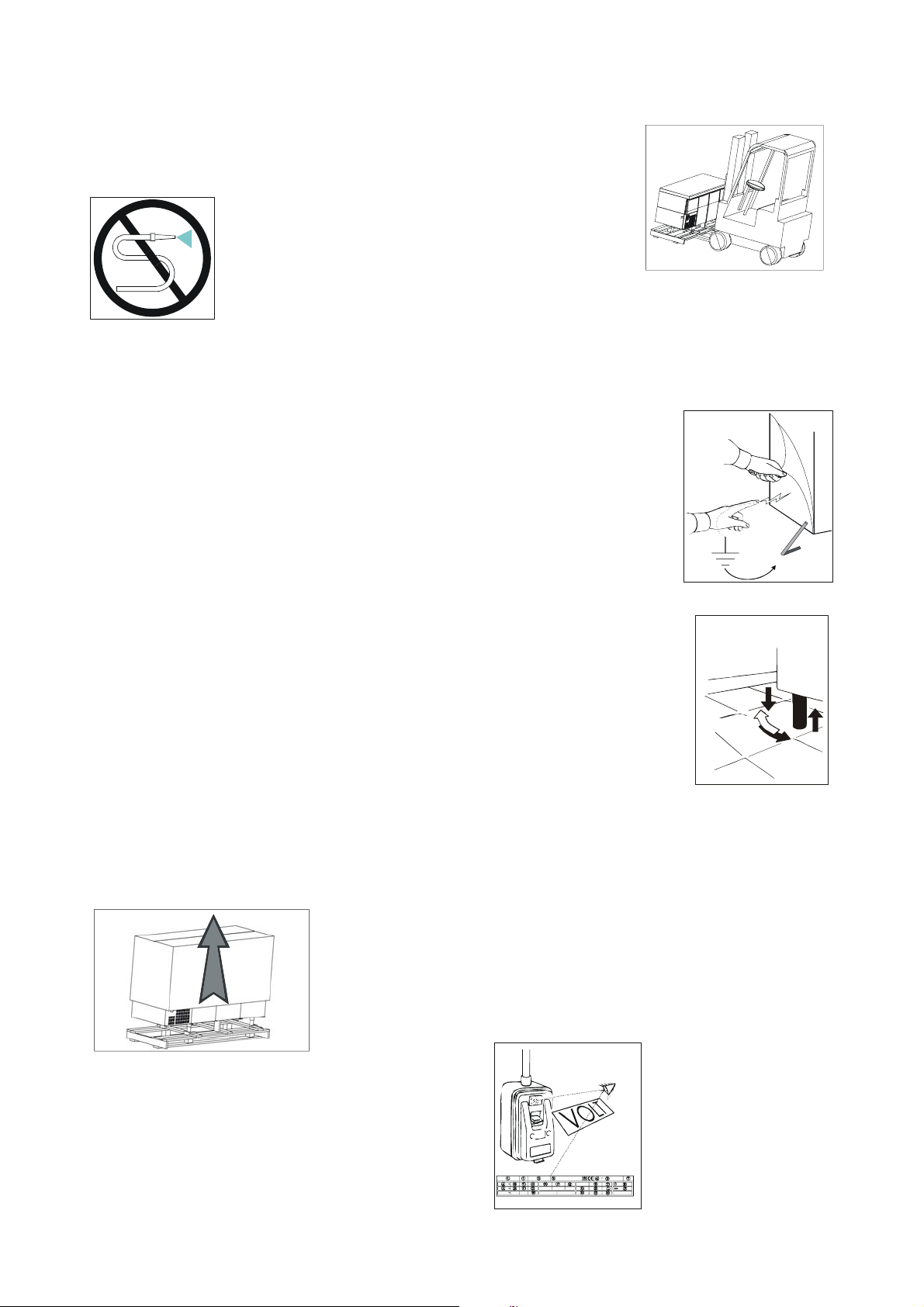
ATENCIÓN: no introduzca en los aparatos bebidas o
alimentos calientes.
ATENCIÓN: no realice la limpieza de las zonas cercanas al
aparato cuando la puerta está abierta.
ATENCIÓN: no use sustancias a base de cloro (lejía, ácido
muriático, etc.) o de cualquier modo tóxicas para la limpieza o
en proximidades de los aparatos.
La limpieza y la manutención de la instalación refrigerante y
de la zona compresores exige la intervención de un técnico
especializado y autorizado, por este motivo no pueden ser
realizadas por personal no idóneo.
Para intervenciones de manutención o en caso de anomalías
desconecte completamente el aparato; solicite la intervención
del SEVICIO DE ASISTENCIA a un centro autorizado y usar
para las eventuales sustituciones repuestos originales. El
incumplimiento de dichas indicaciones puede comprometer el
estado de seguridad del aparato.
No lave el aparato con chorros de
agua directos y a alta presión.
CARACTERÍSTICAS TÉCNICAS
Las características técnicas figuran en un documento especial
anexo al manual de instrucciones.
PUESTA EN OBRA E
INSTALACIÓN
Los aparatos se despachan siempre sobre pallets y con
embalaje de cartón para la protección
Al momento de la entrega y luego de haber realizado el
desembalaje, en caso de daños o partes faltantes, proceda
según lo descrito en el capítulo “NOTAS GENERALES
SOBRE LA ENTREGA”.
ATENCIÓN: Las operaciones de puesta en obra e instalación
deben realizarse por personal especializado.
Quite la caja de embalaje con cuidado para no marcar las
superficies del aparato.
ATENCIÓN: los elementos del embalaje (bolsas de plástico,
poliestirol celular, clavos, etc.) no deben dejarse al alcance de
los niños puesto que constituyen potenciales fuentes de
peligro.
Con un carro de horquillas levante el aparato y llévelo al lugar
de instalación prestando
atención a que la carga
esté bien balanceada.
ATENCIÓN: ya sea para la colocación en el lugar de
instalación como para los desplazamientos futuros no empuje
o arrastre el aparato, para evitar que se vuelque o se causen
daños en algunas partes del mismo
ATENCIÓN: no coloque el aparato cerca de fuentes de calor o
en ambientes con temperatura elevada; esto podría causar un
menor rendimiento del mismo y una excesiva solicitación de la
instalación de refrigeración
Quite la película protectiva del
producto. Esta operación puede
producir descargas fastidiosas
aunque no peligrosas
(electricidad estática). El
inconveniente se elimina o se
reduce considerablemente
manteniendo una mano
siempre en contacto con el
aparato o conectando a tierra la
envoltura externa.
A esta altura se pueden regular las pies del aparato para
nivelarlo.
Nivele el aparato manteniéndolo ligeramente inclinado hacia
atrás para facilitar el perfecto cerrado de las puertas
Limpie con agua tibia y jabón neutro (según lo indicado en el
capítulo “LIMPIEZA”) y monte los posibles accesorios
El aparato está equipado con enchufe eléctrico de tipo
SHUCO
Controle la correspondencia del mismo con las normas
EN60320, EN60335-1 y con las normas nacionales. En el
caso de que no se corresponda, sustituya el enchufe por uno
conforme a las normas
ATENCIÓN: la operación debe ser realizada por un técnico
especializado
Controle que la tensión de la red corresponda a la indicada en
la etiqueta de las características
técnicas del aparato.
6

ATENCIÓN: controle que el tomacorriente de la red esté
provisto de puesta a tierra; de lo contrario provéala
Introduzca luego el enchufe en el tomacorriente específico.
A esta altura las operaciones de puesta en obra se han
terminado.
El aparato, además, se debe incluir en un sistema
equipotencial cuya eficiencia debe ser
verificada de acuerdo a las normas
vigentes. La conexión se realiza
mediante un tornillo marcado con la
sigla “Equipotencial” ubicada en la zona
compresores.
TABLERO DE MANDOS
Todos los aparatos de la línea están equipados con tableros
portamandos con los siguientes mandos:
1) interruptor general
2) interruptor double humedad
3) termorregulador
termorregulador (2) teniendo en cuenta las siguientes
indicaciones:
- presionando la tecla “
visualización del SETPOINT indicado por la intermitencia del
”. Actuando sobre la tecla “ ”y “ ”,
led “
manteniendo presionada la tecla “
modificar el valor de temperatura regulado;
- La tecla “
manteniéndola presionada se obtendrá un aumento más
rápido;
- La tecla “
SETPOINT; manteniéndola presionada se obtendrá una
disminución más rápida;
- Luego de la modificación suelte la tecla “
automáticamente volverá a indicar el valor de temperatura
efectiva del compartimiento;
- Controle en el display del termorregulador (3), luego de un
tiempo necesario, que la temperatura interna de los aparatos
corresponda a la temperatura regulada.
A esta altura y no antes es posible introducir en los aparatos
los alimentos para conservar.
Es posible decidir el valor de humedad que se desea según el
tipo de alimentos que se desea conservar.
Apretando la tecla (2) en posición “I” se obtiene un grado de
humedad del 70%.
Apretando la tecla (2) en posición “II” se obtiene un grado de
humedad del 90%.
” (fig.e) aumenta los valores de SETPOINT;
” (fig.f) disminuye los valores de
fig. d
” (fig.d) se obtendrá la
”, será posible
”el display
1 2 3
PUESTA EN MARCHA Y
FUNCIONAMIENTO
Para poner en marcha el aparato realice la siguientes
operaciones:
enchufarla en el tomacorriente de red ;
coloque el interruptor de línea en la posición ON;
presionar el interruptor general (1), se encenderá la luz verde
del interruptor general;
a esta altura es posible colocar la temperatura de
funcionamiento a través de una adecuada regulación del
fig. e
fig. f
7
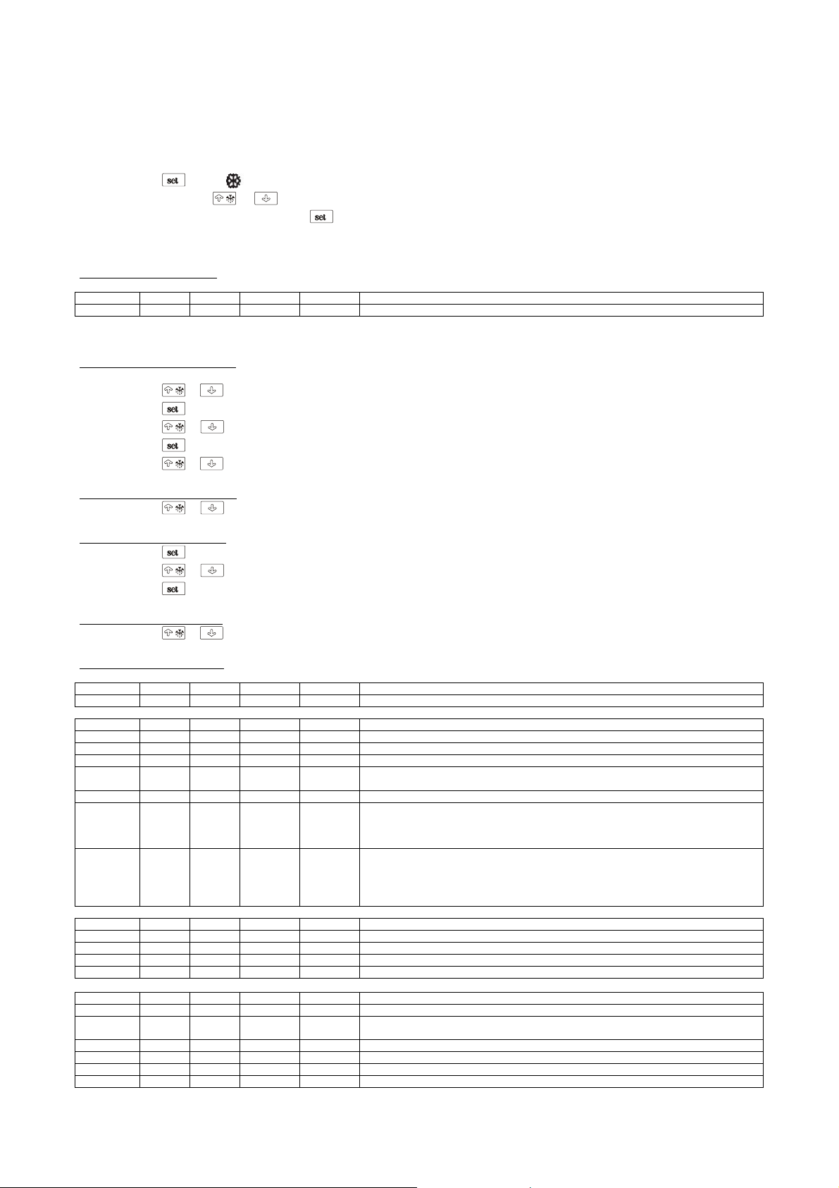
PUNTO DE AJUSTE DE TRABAJO Y PARAMETROS DE CONFIGURACION
Programación del punto de ajuste de trabajo
• asegurarse que el teclado no sea bloqueado y que no esté en cursoalguno procedimiento
• pulse
• actuando sobre
• después de la modificación apretar
Es además posible programar el punto de ajuste de trabajo a través elparámetro SP.
Puntos de ajuste de trabajo
LABEL MIN. MAS. U.M. FABR. PUNTOS DE AJUSTE DE TRABAJO
r1 r2 °C/°F (1) -2 punto de ajuste de trabajo
Programación de los parámetros de configuración
Para acceder al procedimiento:
• asegurarse que no esté en curso alguno procedimiento
• pulse
• pulse
• pulse
• pulse
• pulse
Para seleccionar un parámetro:
• pulse
Para modificar un parámetro:
• pulse
• pulse
• pulse
Para salir del procedimiento:
• pulse
Parámetros de configuración
LABEL MIN. MAS. U.M. FABR. PUNTOS DE AJUSTE DE TRABAJO
SP r1 r2 °C/°F (1) -2 punto de ajuste de trabajo
LABEL MIN. MAS. U.M. FABR. ENTRADAS DE MEDIDA
CA1 -25 25 °C/°F (1) -0,5 offset sonda cámara
CA2 -25 25 °C/°F (1) 0 offset sonda evaporador
P0 0 1 - 1 tipo de sonda (0=PTC, 1=NTC)
P1 0 1 - 0
P2 0 1 - 0 unidad de medida temperatura (2) (0=°C, 1=°F)
P3 0 2 - 1
P5 0 4 - 0
LABEL MIN. MAS. U.M. FABR. REGULADOR PRINCIPAL
r0 0.1 15 °C/°F (1) 3,5 diferencial del punto de ajuste de trabajo
r1 -99 r2 °C/°F (1) -2 mínimo punto de ajuste de trabajo
r2 r1 99 °C/°F (1) 8 máximo punto de ajuste de trabajo
r3 0 1 - 0 bloqueo de la modificación del punto de ajuste de trabajo (1=SI)
LABEL MIN. MAS. U.M. FABR. PROTECCIONES DEL COMPRESOR
C0 0 240 min 0 retardo compresor del encendido del instrumento
C1 0 240 min 5
C2 0 240 min 3 duración mínima del apagamiento del compresor
C3 0 240 s 10 duración mínima del encendido del compresor
C4 0 240 min 10 duración del apagamiento del compresor durante el error sonda cámara; se vea también C5
C5 0 240 min 10 duración del encendido del compresor durante el error sonda cámara; se vea también C4
el LED relampagueará
o dentro de 15 segundos será posible modificar el valor de temperatura programado
para confirmar o, en alternativa, no actuar durante 15 segundos.
y por 4 s: el display visualizará “PA”
o dentro de 15 s para programar “-19”
o no obres por 15 s
y por 4 s: el display visualizará “SP”
o
o dentro de 15 s
o no obres por 15 s.
y por 4 s o no obres por 60 s.
punto decimal grado Celsius (por la cantidad visualizada durante el normal
funcionamiento) (1=SI)
función de la sonda evaporador
0=sonda ausente
1=sonda de desescarche y sonda por termostatar el ventilador del evaporador
2=sonda por termostatar el ventilador del evaporador
cantidad visualizada durante el normal funcionamiento
0=temperatura de la cámara
1=punto de ajuste de trabajo
2=temperatura del evaporador
3=“temperatura de la cámara - temperatura del evaporador”
tiempo mínimo entre dos encendidos consecutivos del compresor; también retardo
compresor del fin del error sonda cámara (3)
8

LABEL MIN. MAS. U.M. FABR. DESESCARCHE
d0 0 99 h 6
d1 0 1 - 0 tipo de desescarche (0=eléctrico, 1=a gas caliente)
d2 -99 99 °C/°F (1) 8 temperatura di fin desescarche (sólo si P3 = 1)
d3 0 99 min 30
d4 0 1 - 0 desescarche al encendido del instrumento (1 = SI)
d5 0 99 min 0 retardo desescarche del encendido del instrumento (sólo si d4 = 1)
d6 0 1 - 1
d7 0 15 min 3 duración del goteo
d8 0 2 _ 0
d9 -99 99 °C/°F (1) 0
dA 0 99 min 0
LABEL MIN. MAS. U.M. FABR. ALARMAS DE TEMPERATURA
A0 0 2 - 0
A1 -99 99 °C/°F (1) -2
A2 0 2 - 1
A4 -99 99 °C/°F (1) 15
A5 0 2 - 1
A6 0 240 min 120 retardo alarma de temp e ratura de máxima de l encendid o del instru m ento (sólo s i A3 = 0)
A7 0 240 min 15 retardo alarma de temperatura
A8 0 240 min 60
LABEL MIN. MAS. U.M. FABR. VENTILADOR DEL EVAPORADOR
F0 0 4 - 1
F1 -99 99 °C/°F (1) -1
F2 0 2 - 0
F3 0 15 min 3 duración del paro del ventilador del evaporador
LABEL MIN. MAS. U.M. FABR. RED SERIAL (MODBUS)
LA 1 247 - 1 dirección instrumento
Lb 0 3 - 2
LP 0 2 - 2
(1) la unidad de medida depende del parámetro P2
(2) programar oportunamente los parámetros relativos a los reguladores después de la modificación del parámetro P2
(3) si el parámetro C1 es programado a 0, el retardo del fin del error sonda cámara será en todo caso de 2 min
(4) el diferencial del parámetro es de 2,0 °C/4 °F
intervalo de desescarche; se vea también d8 (6)
0=el desescarche a intervalos no será activado nunca
duración del desescarche si P3 = 0 o 2; duración máxima del desescarche si P3 = 1
(0=el desescarche no será activado nunca)
temperatura visualizada durante el desescarche
0= temperatura de la cámara
1= si a la activación del desescarche la temperatura de la cámara está por debajo de
“punto de ajustede trabajo + r0”, a lo sumo “punto de ajuste de trabajo + r0”; si a la
activación del desescarche latemperatura de la cámara está por encima de “punto de
ajuste de trabajo + r0”, a lo sumo la temperatura de la cámara a la activación del
desescarche (7)
tipo de intervalo de desescarche
0=el desescarche será activado cuando el instrumento haya quedado encendido por el
tiempo d0
1=el desescarche será activado cuando el compresor haya quedado encendido por el
tiempo d0
2=el desescarche será activado cuando la temperatura del evaporador haya quedada por
debajo de la temperatura d9 por el tiempo d0 (8)
temperatura del evaporador por encima de la cual la cuenta del intervalo de desescarche
es suspendido (sólo si d8 = 2)
duración mínima del encendido del compresor a la activación del desescarche para que
éste pueda ser activado (sólo si d1 = 1) (9)
temperatura asociada a la alarma de temperatura de mínima
0=temperatura de la cámara
1=temperatura del evaporador (10)
temperatura por debajo de la cual es activada la alarma de temperatura de mínima; se
vean también A0 y A2 (4)
tipo de alarma de temperatura de mínima
0=alarma ausente
1=relativa al punto de ajuste de trabajo (o bien “punto de ajuste de trabajo - A1”;
considerar A1 sinseñal)
2=absoluta (o bien A1)
temperatura por encima de la cual es activada la alarma de temperatura de máxima; se
vean también A3y A5 (4)
tipo de alarma de temperatura de máxima
0=alarma ausente
1=relativa al punto de ajuste de trabajo (o bien “punto de ajuste de trabajo + A4”;
considerar A4 sinseñal)
2=absoluta (o bien A4)
retardo alarma de temperatura de máxima del fin del paro del ventilador del evaporador
(sólo si A3 = 0)(12)
actividad del ventilador del evaporador durante el normal funcionamiento
0=apagado
1=encendido
2=paralelamente al compresor
3=dependiente de F1 (14)
4=apagado si el compresor es apagado , dependi ente de F1 si el compre sor es en cendid o (14)
temperatura del evaporador por encima de la cual el ventilador del evaporador es
apagado (sólo siF0 = 3 o 4) (4)
actividad del ventilador del evaporador durante el desescarche y el goteo
0=apagado
1=encendido
2=dependiente de F0
baud rate
0=2.400 baud
1=4.800 baud
2=9.600 baud
3=19.200 baud
Paridad
0=none (ninguna paridad)
1=odd (impar)
2=even (par)
9

(6) el instrumento memoriza la cuenta del intervalo de desescarche cada 30 min; la modificación del parámetro d0 tiene efecto de la conclusióndel anterior
intervalo de desescarche o de la activación de un desescarche de modo manual
(7) el display restablece el normal funcionamiento cuando, finido el paro del ventilador del evaporador, la temperatura de la cámara va pordebajo de la que
ha parado el display (o si se manifiesta una alarma de temperatura
(8) si el parámetro P3 es programado a 0 o 2, el instrumento funcionará como si el parámetro d8 fuera programado a 0
(9) si a la activación del desescarche la duración del encendido del compresor es inferior al tiempo establecido con el parámetro dA, elcompresor quedará
ulteriormente encendido por la fracción de tiempo necesario a completarlo
(10) si el parámetro P3 es programado a 0, el instrumento funcionará como si el parámetro A0 fuera programado a 0
(12) durante el desescarche, el goteo y el paro del ventilador del evaporador las alarmas de temperatura son ausentes, a condición que éste sehayan
manifestado después de la activación del desescarche
(14) si el parámetro P3 es programado a 0, el instrumento funcionará como si el parámetro F0 fuera programado a 2
CARGA DEL PRODUCTO
• Distribuir el producto en el interior de los vanos
refrigerados de manera uniforme para permitir una buena
circulación del aire;
• Evitar obstruir las zonas de ventilación de la instalación
de refrigeración colocado sobre la parte izquierda del
vano;
• Evitar guardar los alimentos que necesitan bajas
temperaturas de conservación en el último cajón inferior
derecho;
• Cubrir o envolver los alimentos antes de introducirlos en
el interior del aparato con adecuadas películas
protectoras;
• No introducir en el aparato alimentos o bebidas
demasiado calientes;
• No dejar las puertas abiertas más de lo necesario
durante el retiro o la introducción de los alimentos.
PARADA
En cualquier condición para interrumpir el funcionamiento del
aparato es suficiente presionar en posición OFF el interruptor
general; se apagará la luz de la tecla.
Para aislar la base de la tensión eléctrica quite el enchufe
eléctrico del tomacorriente.
I DESCONGELACIÓN
La descongelación de los aparatos es comp letament e automática
y se activa gracias a una resistencia eléctrica especial.
La descongelación está regulada por el termorregulador.
La descongelación se activa cada 6 horas. La duración del
ciclo de descongelación está regulada por la CABINA
FRIGORIFICA.
Es posible activar en cualquier momento un ciclo de
descongelación presionando durante 4 segundos el botón
” (vedi fig. e ) .
“
Terminada la descongelación manual se restablecerán las
condiciones anteriores de descongelación automática.
El aparato está equipado con evaporación automática del
líquido de condensación.
ALARMAS
El botón “ ”sirve para detener las alarmas.
Sobre el display se visualizan eventuales alarmas y señales:
Luz “
Luz “
Luz “
Luz “
descongelación o presencia de goteo.
Luz “
”encendido indica compresor activo.
”intermitente indica retardo activación compresor.
”encendido indica descongelación en curso.
”intermitente indica atraso en la activación de
” encendido indica ventiladores cámara activos.
Luz “
evaporador.
“E0” con luz intermitente sobre el display puede indicar una
de las siguientes anomalías: tipo sonda cámara no correcto,
defecto de la sonda cámara o de las conexiones, temperatura
relevada fuera de los límites de medición.
“E1” con luz intermitente sobre el display puede indicar una
de las siguientes anomalías: tipo sonda
evaporador no correcto, defecto de la sonda evaporador o de
las conexiones, temperatura relevada fuera
de los límites de medición.
“E2” intermitente sobre el display: corrupción de los datos de
configuración en m e mo r ia ; pr obar a apagar y
volver a encender el aparato, si la alarma non desaparece,
sustituir el termorregulador.
Temperatura de la cámara: con display indicando un valor
correcto pero intermitente, la temperatura relevada por la
sonda está fuera de los límites prefijados.
IRREGULARIDADES DE
FUNCIONAMIENTO
En caso de irregularidades de funcionamiento, antes de
consultar el servicio de asistencia, verifique que:
• el interruptor general esté iluminado y que haya tensión en
• el valor de la temperatura regulado sea el deseado
• las puertas estén perfectamente cerradas
• el aparato no esté colocado cerca de fuentes de calor
• el condensador esté limpio y el ventilador funcione
• el evaporador no esté excesivamente congelado
En caso que dichos controles hayan dado un resultado
negativo, diríjase al servicio de asistencia de zona
suministrando las indicaciones del modelo y número de
matrícula colocados en la placa de las características
LIMPIEZA DIARIA
Para garantizar una higiene y una conservación perfectas del
aparato es conveniente efectuar periódicamente y/o
diariamente las siguientes operaciones de limpieza indicadas
a continuación:
1. Limpiar cuidadosamente las superficies externas del
• El detergente no debe contener cloro y no debe ser
• Los detergentes aconsejados son los siguientes tipos:
” intermitente indica un bloqueo del ventilador del
la red
regularmente
aparato pasándole con una esponja suave embebida en
agua y detergente neutro, y exprimida, únicamente en el
sentido del satinado, teniendo cuidado especialmente con
la limpieza del plano de trabajo y de las puertas y cajones
en la zona manija.
abrasivo.
- Detergente desinfectante de acción combinada;
(con tensioactivos no iónicos, benzalconio cloruro,
sustancias quelantes y pH tampón)
- Detergente para laboratorio, neutro, para lavado manual;
10

(con tensioactivos aniónicos y no iónicos)
- Desengrasante para ambientes alimenticios;
(con tensioactivos aniónicos y EDTA)
• Antes del uso diluir eventualmente los detergentes según
las instrucciones incluidas en la etiqueta.
• Dejar actuar los detergentes al menos 5 minutos.
• Enjuagar cuidadosamente las paredes del aparato con
una esponja pasada varias veces en agua corriente.
• Secar con atención utilizando una esponja limpia.
ATENCION: evitar absolutamente el uso de herramientas o
elementos que puedan rayar el equipo con la consiguiente
formación de herrumbre.
MANCHAS DE ALIMENTOS Y
RESIDUOS ENDURECIDOS
En caso de presencia de manchas de comida o residuos en el
aparato, lavar con agua y quitarlos antes de que estos puedan
endurecerse.
Si los residuos ya están endurecidos proceder como indicado
a continuación:
1. Usar una esponja suave humedecida en agua tibia y
detergente neutro (se pueden usar esos previstos para la
limpieza diaria, a la concentración más alta entre
aquellas previstas en la etiqueta).
2. Humedecer el residuo endurecido de modo tal que se
mantenga húmedo por al menos 30 minutos repasando
más o menos cada 5 minutos la esponja humedecida en
agua y detergente sobre la suciedad endurecida.
3. Al final del ablandamiento quitar el residuo con la esponja
humedecida en agua y detergente neutro.
4. Si fuera necesario, recurrir a una espátula de madera o a
una esponja fina de acero inoxidable, teniendo cuidado
de no dañar la superficie del frigorífico.
5. Al final del procedimiento se aconseja un ciclo de
limpieza diaria de todas las superficies internas del
aparato.
6. A limpieza terminada enjuagar cuidadosamente con una
esponja pasada varias veces en agua corriente.
7. Secar con atención utilizando una esponja limpia.
También las zonas debajo y cercanas a la cabina deben estar
limpias y mantenidas en perfecta higiene.
Limpiar con agua y jabón o detergente neutro.
Proteger las chapas con cera con siliconas.
LIMPIEZA Y MANUTENCIÓN
GENERAL
Para un rendimiento constante del aparato se aconseja
realizar las operaciones de limpieza y manutención general
más de una vez al año
Antes de comenzar con las operaciones realice lo siguiente:
• lleve el interruptor colocado en el tablero mandos a la
posición OFF
• lleve el interruptor de la red a la posición OFF
• desconecte el enchufe del cable de alimentación y
espere que el aparato se haya descongelado
completamente
• con un aspirador, un pincel o un cepillo no metálico,
limpie con atención el grupo refrigerante y especialmente
la batería con aletas.
ATENCIÓN: para la limpieza y manutención del equipo
refrigerante y de la zona compresores es necesaria la
intervención de un técnico especializado y autorizado; por este
motivo no debe ser efectuado por personal no idóneo.
Limpiar las superficies externas e internas del aparato
siguiendo las indicaciones citadas en el párrafo limpieza
diaria.
Aclare abundantemente con agua pura y seque.
ATENCIÓN: (como ya indicado en otra parte del manual) no
lave el aparato con chorros de agua directos y a alta presión
A esta altura las operaciones de manutención y limpieza
general se han terminado.
INTERRUPCIÓN DEL USO
En el caso de inactividad prolongada del aparato proceda de
la siguiente manera:
• lleve el interruptor colocado en el tablero de mandos a la
posición OFF
• lleve el interruptor de la red a la posición OFF
• desconecte el enchufe del cable de alimentación y espere
que se haya producido la descongelación total del aparato
• Vacíe la base y límpiela como indicado en el capítulo
“LIMPIEZA”
• Deje las puertas y los cajones del aparato entre-abiertos
para evitar la formación de olores desagradables
CONSEJOS ÚTILES PARA LA
MANUTENCIÓN DEL ACERO
INOXIDABLE
Las partes externas de las bases refrigeradas están
construidas en acero inoxidable AISI 304 18/10
Para la limpieza y manutención de las partes construidas en
acero inoxidable, atenerse a lo que a continuación se indica,
teniendo en cuenta que el principal y fundamental objetivo es
garantizar la no-toxicidad y la máxima higiene de de los
productos tratados.
El acero inoxidable tiene una capa sutil de óxido que impide la
formación de herrumbre. Existen sustancias o detergentes que
pueden destruir o dañar esta capa y dar así origen a la
corrosión. Antes de usar cualquier producto detergente
consulte siempre su proveedor de confianza, sobre las
características del producto.
En caso de rayaduras en las superficies, es necesario pulirlas
con lana de ACERO INOXIDABLE finísima o esponjas
abrasivas de material sintético fibroso, frotando en el sentido
del satinado.
ATENCIÓN: para la limpieza del ACERO INOXIDABLE no use
nunca esponjillas de hierro y no las deje apoyadas sobre las
superficies puesto que los depósitos ferrosos muy pequeños
podrían quedar sobre las mismas y producir formaciones de
herrumbre por contaminación, comprometiendo el estado de
higiene.
DESECHADO
ALMACENAJE DE LOS DESHECHOS
Al final del ciclo de vida del producto, no eliminar en el medio
ambiente el aparato. Las puertas tendrán que desmontarse
antes de la eliminación del aparato. Está admitido u
almacenaje provvisorio de los deshechos especiales, en vista
de una eliminación, por medio del tratamiento y/o almacenaje
definitivo.
11

De todos modos se deben cumplir con las leyes vigentes en
cuanto a la tutela del ambiente, en el país del utilizador.
PROCEDIMENTOS RELATIVOS A LAS MACROOPERACIONES DE DESARMADO DEL APARATO
Cada País tiene legislaciones diferentes, por tanto, se tienen
que cumplir las prescripciones impuestas por las leyes y
entidades encargadas de los Países donde se realiza la
demolición.
En general, es necesario devolver el frigorífico a los centros
especializados para el retiro/demolición. Desmontar el
frigorífico, agrupando los componentes de acuerdo a su
naturaleza química, ricordando que en el compresor hay
aceite lubricador y fluido refrigerante, que se pueden
recuperar y volver a usar, y que los componentes del
frigorífico son deshechos especiales asimilables a los
urbanos. Hacer que el aparato sea inutilizable para su
eliminación, sacando el cable de alimentación y cualquier
dispositivo de cierre espacios, con el fin de evitar que alguien
pueda quedar encerrado en el interior.
LAS OPERACIONES DE DESARMADO, DE TODOS
MODOS, TIENE QUE SER REALIZADA POR PERSONAL
ESPECIALIZADO.
ELIMINACIÓN SEGURA DE LOS RESIDUOS DE
APARATOS ELÉCTRICOS Y ELECTR ÓNICOS (DIRECTIVA
RAEE 2002/96/CE)
No abandonar material contaminante en el ambiente.
Efectuar su eliminación en conformidad con lo dispuesto
por las leyes vigentes en esta materia.
Conforme con la Directiva RAEE 2002/96/CE (sobre residuos
de aparatos eléctricos y electrónicos), al efectuar la eliminación de los equipos el usuario deberá entregarlos en instalaciones de recogida específicas y autorizadas, o bien -en el
momento de efectuar una nueva compra- deberá entregarlos
aún montados al distribuidor.
Todos los aparatos que deben ser eliminados de modo selectivo y en conformidad con lo dispuesto por la Directiva RAEE
2002/96/CE, aparecen identificados mediante un símbolo es-
pecífico
La eliminación abusiva de residuos de aparatos eléctricos
y electrónicos será sancionada en conformidad con lo
dispuesto por las leyes vigentes en el territorio en que se
ha cometido la infracción.
.
FICHA TÉCNICA DEL
REFRIGERANTE
1) R404a: componentes del fluido
• Trifluoroetano (HFC 143a) 52%
• Pentafluoroetano (HFC 125) 44%
• Tetrafluoroetano (HFC 134a) 4%
GWP = 3750
ODP = 0
2) Identificación de peligros
Fuertes exposiciones por inhalación pueden producir efectos
anestésicos. Las fuertes exposiciones pueden producir
anomalias del ritmo cardiaco y ocasionar una muerte
repentina. El producto atomizado, salpicado o rociando puede
producir ustiones por congelación en los ojos o la piel.
3) Medidas de primer auxilio
• Inhalación:
alejar el accidentado de exposición al producto y mantenerlo
en el calor y en estado de reposo. Si es necesario, darle
oxigeno. Practicarle la respiración artificial si la respiración
natural se ha parado o amenaza con hacerlo. En caso de paro
cardiaco practicarle un masaje cardiaco externo. Solicitar
asistencia médica inmediata.
• Contacto con la piel:
echar agua a las zonas golpeadas para que descongelen.
Quitar los vestidos contaminados.
ATENCIÓN: los vestidos pueden adherirse a la piel en caso
de ustiones por congelación.
En caso de contacto con la piel lavarla inmediata y
abundantemente con agua tibia. Tras producirse algún
sintoma (irritación o formación de ampollas) solicitar asistencia
médica.
• Contacto con los ojos:
lavarlos inmediatamente con solución para lavado ocular o
agua limpia manteniendo abiertos los párpados, por al menos
10 minutos. Solicitar asistencia médica.
• Ingestión:
puede provocar vómito. Si el accidentado está consciente,
hacer que se enjague la boca y beda unos 200-300 ml de
agua. Solicitar asistencia médica inmediata.
• Tratamientos médicos ulteriores:
tratamiento sintomático y terapia de sostén, si necesarios. No
dar al accidentado adrenalina o medicamentos
simpaticomiméticos similares por el riesgo de aritmia cardiaca
con posible paro cardiaco.
4) Informaciones ecológicas
Persistencia y degradación:
• HFC 143a:
se descompone lentamente en la atmósfera inferior
(troposfera). Su duración en la atmósfera es de 55 años.
• HFC 125:
se descompone lentamente en la atmósfera inferior
(troposfera). Su duración en la atmósfera es de 40 años.
• HFC 134a:
se descompone con cierta rapidez en la atmósfera inferior
(troposfera). Su duración en la atmósfera es de 15,6 años.
• HFCs 134a, 125, 134a:
no influyen en la polución fotoquimica (es decir, no están
comprendidos entre los componentes orgánicos volátiles VOC – segun cuanto establecido en el acuerdo UNECE). No
producen rarefacción del ozono.
Los residuos de producto dispersados en la atmósfera no
producen contaminación de las aguas a largo plazo.
El esquema eléctrico figura en la última página del
manual.
POS: DESCRIPCIÓN
1 COMPRESOR
2 VENTILADOR CONDENSADOR
3 TABLERO DE BORNES
6 INTERRUPTOR GENERAL
8 TOMA ELÉCTRICA
9 VENTILADOR EVAPORADOR
14 REGULADOR HUMEDAD CON INDICATOR
21 RESISTENCIA DESPOSIT.DESCONG.
44 RELAIS COMPRESOR
69 BORNE DE TIERRA
90 TERMOREG. DGT
102 TERMOSTATO DE SEGURIDAD
12


INDEX
BESCHRIJVING APPARAAT 5
IDENTIFICATIE-ETIKET 5
ALGEMENE OPMERKINGEN BIJ DE AFLEVERING 5
VEILIGHEIDSVOORSCHRIFTEN 5
TECHNISCHE EIGENSCHAPPEN 6
INGEBRUIKNAME EN INSTALLATIE 6
BEDIENINGSPANELEN 7
OPSTARTEN EN FUNCTIONERING 7
INSTELWAARDE EN CONFIGURATIEPARAMETERS 8
INLEGGEN VAN PRODUCTEN 10
STILZETTEN 10
ONTDOOIING 10
ALARMSIGNALEN 10
ONREGELMATIGHEDEN IN DE FUNCTIONERING 10
DAGELIJKSE REINIGING 10
VOEDSELVLEKKEN EN HARDGEWORDEN RESTEN 11
REINIGING EN ALGEMEEN ONDERHOUD 11
GEBRUIKSONDERBREKINGEN 11
NUTTIGE RAADGEVINGEN VOOR HET ONDERHOUD VAN ROESTVRIJ STAAL 11
ONTMANTELING 12
SPECIFICATIES VAN DE KOELVLOEISTOF 12
4

BESCHRIJVING APPARAAT
Dit apparaat is ontworpen voor het koelen en het bewaren van
levensmiddelen. Elk ader gebruik moet als oneigenlijk
beschouwd worden.
LEP OP: de apparaten zijn niet geschikt om buiten
geïnstalleerd te worden of op plaatsen die aan de inwerking
van weersinvloeden blootgesteld zijn.
De fabrikant kan op geen enkele wijze aansprakelijk
gesteld worden voor onjuist gebruik van de producten.
De basiselementen hebben aan de bovenkant een werkblad,
dat ook beschikbaar is met achtersteuntjes : ze zijn ook
beschikbaar zonder blad met soortgelijke koelvermogens.
Het bedieningspaneel is voorzien van digitale
temperatuurregeling en algemene schakelaar.
De motoreenheid bevindt zich links van het basiselement in
een geschikte ruimte.
De verdamper bevindt zich binnen in de koelruimte, één voor
iedere ruimte, en wordt afgeschermd met geschikte
metaalplaten.
De interne ventilatie wordt gerealiseerd met beveiligde boven
de verdamper geplaatste tangentiële ventilatoren.
Het apparaat verdampt de condens automatisch.
IDENTIFICATIE-ETIKET
Het identificatie-etiket zit definitief op het product en levert een
serie belangrijke aanwijzingen over de technische en
constructieve kenmerken van het product.
voorzorgsmaatregelen, die in deze handleiding opgenomen
zijn, op te volgen.
Denkt u eraan, dat iedere reproductie van de handleiding
verboden is, en dat vanwege een voortdurende studie gericht
op vernieuwing en verbetering van de technologische kwaliteit,
de hier weergegeven kenmerken zonder bericht vooraf zouden
kunnen veranderen.
VEILIGHEIDSVOORSCHRIFTEN
LET OP : vóór iedere onderhouds- of reinigingswerkzaamheid
de apparatuur isoleren van electrische energiebronnen
De hoofdschakelaar op stand OFF zetten.
DE STEKKER UIT HET STOPCONTACT HALEN.
TQPN
INHOUD VAN DE VAKJES VAN HET TECHNISCHE PLAATJE
1) model
2) fabrikant
3) EEG-merk
4) bouwjaar
5) registratienummer
6) electrische isolatieklasse
7) electrische beveiligingsklasse
A) electrische voedingsspanning
B) electrische spanningsintensiteit
C) nominale frequentie
D) nominaal vermogen
E) nominaal lampenvermogen
F) zekeringsstroom
G) soort koelgas
H) hoeveelheid koelgas
L) temperatuurklasse koelinstallatie
M) max. voedingsdruk
N) ventilatorvermogen
P) draaisnelheid ventilator
Q) ventilatorvoorkeur
R) AEEA symbool
S) stoomvermogen
T) stoomdruk
W) vermogen verwarmingselementen
Bij iedere mededeling aan de fabrikant altijd het
REGISTRATIENUMMER van het apparaat vermelden.
ALGEMENE OPMERKINGEN BIJ
DE AFLEVERING
Bij de aflevering controleren, of de verpakking intact is, en of
deze tijdens het transport geen schade opgelopen heeft.
Controleren, of de kenmerken van het product overeenkomen
met de details van de opgegeven order. Als dat niet zo zou
zijn, direct contact opnemen met de wederverkoper.
Met de felicitaties voor uw uitstekende keuze hopen wij, dat u
onze basiskoelelementen op de beste manier zult kunnen
gebruiken door de noodzakelijke aanwijzingen en
LET OP : geen stopcontacten of stekkers zonder aarder
gebruiken.
Het netstopcontact moet van een AARDER voorzien zijn.
LET OP : voor de aansluiting op het stroomnet geen
tussenstekkers of verlengsnoeren gebruiken.
LET OP : zolang wachten, als noodzakelijk is, om de
ingestelde temperatuur te bereiken, alvorens er het te bewaren
voedsel in te zetten.
De levensmiddelen altijd met daarvoor bestemd folie afdekken,
alvorens het in de apparaten te zetten.
LET OP : geen warme dranken of gerechten in de apparaten
zette.

LET OP : de ruimte rondom de apparaten niet schoonmaken,
terwijl de deur open staat.
LET OP : geen stoffen op chloorbasis (bleekwater, zoutzuur
enz.) en in geen geval giftige stoffen gebruiken voor de
reiniging of in de buurt van de apparaten.
De reiniging en het onderhoud van de koelinstallatie en van de
compressorruimte verlangt de tussenkomst van een
gespecialiseerde bevoegde technicus; daarom kan dit niet
door onbevoegd personeel uitgevoerd worden.
Voor onderhoudswerkzaamheden of in geval van
mankementen de apparatuur compleet uitschakelen, de
tussenkomst van de SERVICEDIENST vragen bij een
bevoegd centrum en voor de eventuele vervangingen originele
reserve-onderdelen gebruiken. Het niet in acht nemen van
hetgeen hierboven vermeld is, kan de veiligheid van de
apparaten in gevaar brengen.
De apparatuur niet met directe en
onder hoge druk staande
waterstralen schoonmaken.
TECHNISCHE EIGENSCHAPPEN
De technische eigenschappen zijn op het betreffende blad in
bijlage bij de handleiding weergegeven.
INGEBRUIKNAME EN
INSTALLATIE
De apparaten worden altijd op pallets en met een
beschermende kartonnen verpakking verzonden.
Bij ontvangst en na het uitpakken moet men zich in geval van
schade of ontbrekende onderdelen gedragen, zoals
beschreven is in het hoofdstuk "ALGEMENE OPMERKINGEN
BIJ DE AFLEVERING".
LET OP : de werkzaamheden voor ingebruikname en
installatie moeten door gespecialiseerd personeel uitgevoerd
worden.
De verpakkingsdoos verwijderen en erop letten de
oppervlakken van het apparaat niet te deuken.
LET OP : de verpakkingselementen (plastic zakken,
schuimplastic, spijkers enz.) mogen niet binnen het bereik van
kinderen gelaten worden, omdat dit potentiële bronnen van
gevaar zijn
Met een vorkheftruck het apparaat optillen en naar de
installatieplek brengen,
waarbij men oplet, dat de
last in evenwicht is.
LET OP : zowel bij de plaatsing op de installatieplek als bij
toekomstige verplaatsingen het apparaat niet duwen of slepen,
om te vermijden, dat het omvalt, of schade te berokkenen aan
enig onderdeel daarvan
LET OP : het apparaat niet in de buurt van warmtebronnen of
in ruimten met hoge temperaturen plaatsen; dat zou een lager
rendement ervan of een buitengewone belasting voor de
koelinstallatie kunnen veroorzaken
De beschermfolie van het product verwijderen. Deze handeling
kan vervelende zij het
ongevaarlijke schokken
veroorzaken (statische
electriciteit). Dit ongemak maakt
men ongedaan of vermindert
men behoorlijk door altijd met
één hand contact te houden met
het apparaat of door het
buitenomhulsel met de vloer te
verbinden.
Nu kan men de voetjes van het
apparaat regelen om dit te
nivelleren.
Het apparaat nivelleren door het
iets naar achteren te laten leunen
om de optimale sluiting van de
deuren te bevorderen.
Met lauwwarm water en neutrale zeep schoonmaken (zoals
beschreven in het hoofdstuk "REINIGING") en de eventuele
accessoires monteren.
Het apparaat is uitgerust met een electrische stekker van het
type SHUCO.
Controleren, of deze aan de EN60320, EN60335-1 normen en
aan de nationale normen voldoet. In geval deze daar niet aan
voldoet, de stekker vervangen door één, die daar aan voldoet.
LET OP : deze werkzaamheid moet door een gespecialiseerde
technicus uitgevoerd worden
Controleren, of de netspanning overeenkomt met degene, die
op het plaatje met de technische
kenmerken van het apparaat
aangegeven is.
6

LET OP : controleren, of het netstopcontact geaard is; in geval
van niet daarvoor zorgen
Dan de stekker in het betreffende netstopcontact steken.
Nu zijn de werkzaamheden ter ingebruikname ten einde.
De apparatuur moet ook op een equipotentiaal systeem
aangesloten zijn, waarvan de efficiëntie
volgens de geldende normen
gecontroleerd moet zijn. De aansluiting
wordt uitgevoerd door middel van een
met het "Equipotentiaal"-teken
gemerkte schroef, die in de
compressorenruimte aangebracht is.
BEDIENINGSPANELEN
Alle apparaten uit de serie hebben een bedieningsdashbord
met de volgende commando’s :
1) hoofdschakelaar
2) dubbele vochtigheidsschakelaar
3) thermoregelaar
- toets “
deze ingedrukt te houden, zal men een snellere verhoging
verkrijgen;
- toets “
deze ingedrukt te houden, zal men een snellere verlaging
verkrijgen;
- na de verandering toets “
automatisch opnieuw de reële ruimtetemperatuur gaan tonen;
- op het thermoregelaar -display (3) , na verloop van de
noodzakelijke tijd - controleren, of de interne temperatuur van
de apparaten overeenkomt met de ingestelde temperatuur.
Dan en niet eerder kan men de te bewaren levensmiddelen in
de apparaten zetten.
” (fig.e) verhoogt de SETPOINT-waarden ; door
” (fig.f) verlaagt de SETPOINT-waarden ; door
”loslaten ; het display zal
Het is mogelijk de vochtigheidswaarde in te stellen afhankelijk
van de te conserveren voeding
Door knop (2) op stand “I” te zetten, verkrijgt men een
vochtigheidsgraad van 70%.
Door knop (2) op stand “II” te zetten, verkrijgt men een
vochtigheidsgraad van 90%.
fig. d
1 2 3
OPSTARTEN EN
FUNCTIONERING
Om het apparaat op te starten, de volgende handelingen
uitvoeren:
de stekker in het stopkontakt stoppen;
de netschakelaar op stand ON zetten;
op de hoofdschakelaar (1) drukken; het groene controlelichtje
van de hoofdschakelaar zal gaan branden;
dan is het mogelijk de werktemperatuur in te stellen door
middel van een geschikte instelling van de thermoregelaar (3),
waarbij men de volgende aanwijzingen in gedachten houdt:
- door op knop “
knipperen van het "
display getoond. Door de toets “
gebruiken, terwijl men toets “
mogelijk zijn de ingestelde temperatuurwaarde te veranderen;
” te drukken (fig.d) wordt het door
"-led aangegeven SETPOINT op het
” en “ ”, te
” ingedrukt houdt, zal het
fig. e
fig. f
7
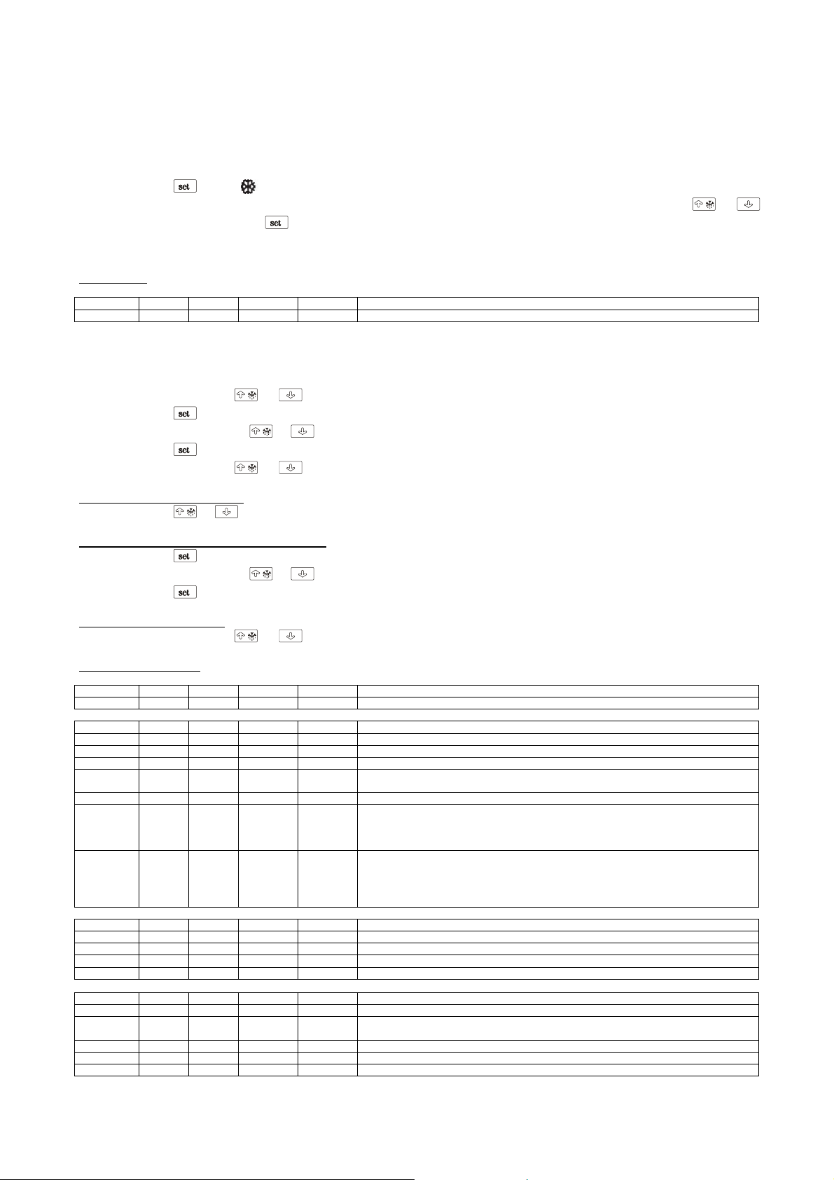
INSTELWAARDE EN CONFIGURATIEPARAMETERS
Instelling setpoint werk
Controleer of het toetsenbord niet is geblokkeerd en dat er geen enkele procedure in uitvoering is
• Druk op
• De ingestelde waarde van de temperatuur kan worden aangepast binnen 15 seconden met behul van de toetsen
• Druk na de aanpassing op
Het is ook mogelijk de setpoint werk in te stellen middels parameter SP.
Setpoint werk
LABEL MIN. MAS. M.E. DEF. SETPOINT WERK
r1 r2 °C/°F (1) -2 setpoint werk
Instelling configuratie-parameters
Om toegang te krijgen tot de procedure:
• Controleer of er geen andere procedure in uitvoering is
• Druk 4 seconden op
• Druk op
• Druk binnen 15 sec. op
• Druk op
• Druk 4 seconden op
Om een parameter te selecteren:
• Druk op
Om de waarde van een parameter aan te passen:
• Druk op
• Druk binnen 15 sec. op
• Druk op
Om de procedure te verlaten:
• Druk 4 seconden op
Configuratie-parameters
LABEL MIN. MAS. M.E. DEF. SETPOINT WERK
SP r1 r2 °C/°F (1) -2 setpoint werk
LABEL MIN. MAS. M.E. DEF. MEETINGANGEN
CA1 -25 25 °C/°F (1) -0,5 offset sonde cel
CA2 -25 25 °C/°F (1) 0 offet sonde verdamper
P0 0 1 - 1 type sonde (0=PTC, 1=NTC)
P1 0 1 - 0
P2 0 1 - 0 Meeteenheid temperatuur (2) (0=°C, 1=°F)
P3 0 2 - 1
P5 0 4 - 0
LABEL MIN. MAS. M.E. DEF. REGELAAR
r0 0.1 15 °C/°F (1) 3,5 Differentieel van de setpoint werk
r1 -99 r2 °C/°F (1) -2 Minimum setpoint werk
r2 r1 99 °C/°F (1) 8 Maximum setpoint werk
r3 0 1 - 0 blokkering van de aanpassing setpoint werk (1=SI)
LABEL MIN. MAS. M.E. DEF. PROTECTIE COMPRESSOR
C0 0 240 min 0 Vertraging compressor vanaf inschakeling van het instrument
C1 0 240 min 5
C2 0 240 min 3 Minimum duur van de uitschakeing van de compressor
C3 0 240 s 10 minimum duur inschakeling compressor
C4 0 240 min 10 duur uitschakeling compressor tijdens fout sonde cel; zie ook C5
de LED gaat knipperen
om te bevestigen of, in plaats daarvan, voer gedurende 15 seconden geen handeling uit.
en ; het instrument geeft “PA” weer
of om “-19” in te stellen
of voer gedurende 15 sec. geen handeling uit
en ; op de display verschijnt “SP”
of
of
o non operare per 15 s
en of voer gedurende 15 sec. geen handeling uit
Graden Celsius decimaal (voor de grootte weergegeven tijdens het normale functioneren)
(1=SI)
functie van de sonde verdamper
0=sonde afwezig
1=sonde ontdooiing en sonde voor de thermostatie ventilator van de verdamper
2=sonde voor de thermostatie ventilator van de verdamper
grootte weergegeven tijdens het normale functioneren
0=temperatuur van de cel
1=setpoint werk
2=temperatuur van de verdamper
3=“temperatuur van de cel - temperatuur van de verdamper”
minimum tijd tussen twee achtereenvolgende inschakelingen van de compressor; ook
vertraging compressor vanaf beëindiging fout sonde cel (3)
of
8

C5 0 240 min 10 duur inschakeling compressor tijdens fout sonde cel; zie ook C4
LABEL MIN. MAS. M.E. DEF. ONTDOOIING
d0 0 99 h 6
d1 0 1 - 0 type ontdooiing (0=electrisch, 1=op warm gas)
d2 -99 99 °C/°F (1) 8 temperatuur einde ontdooiing (alleen indien P3 = 1)
d3 0 99 min 30
d4 0 1 - 0 Ontdooiing bij de inschakeling van het instrument (1 = SI)
d5 0 99 min 0 Vertraging ontdooiing vanaf de inschakeling van het instrument (alleen indien d4 = 1)
d6 0 1 - 1
d7 0 15 min 3 duur van het uitdruppelen
d8 0 2 _ 0
d9 -99 99 °C/°F (1) 0
dA 0 99 min 0
LABEL MIN. MAS. M.E. DEF. TEMPERATUUR ALARM
A0 0 2 - 0
A1 -99 99 °C/°F (1) -2
A2 0 2 - 1
A4 -99 99 °C/°F (1) 15
A5 0 2 - 1
A6 0 240 min 120
A7 0 240 min 15 vertraging temperatuur alarm
A8 0 240 min 60
LABEL MIN. MAS. M.E. DEF. VENTILATOR VAN DE VERDAMPER
F0 0 4 - 1
F1 -99 99 °C/°F (1) -1
F2 0 2 - 0
F3 0 15 min 3 duur stilstand ventilator van de verdamper
LABEL MIN. MAS. M.E. DEF. SERIEEL NET (MODBUS)
LA 1 247 - 1 adres instrument
Lb 0 3 - 2
LP 0 2 - 2
(1) de meeteenheid is afhankelijk van parameter P2
(2) de parameters met betrekking tot de regelaars op het juiste moment instellen na de aanpassing van parameter P2
(3) indien parameter C1 is ingesteld op 0, de vertraging vanaf het einde van de fout sonde cel is, hoe dan ook 2 min
(4) het differentieel van de parameter is 2,0 °C/4 °F
Interval ontdooiing; zie ook d8(5)
(0=de ontdooiing in intervallen wordt nooit geactiveerd)
duur van de ontdooiing indien P3 = 0 of 2; maximum duur van de ontdooiing indien P3 = 1
(0=de ontdooiing wordt nooit geactiveerd)
Temperatuur weergegeven tijdens de ontdooiing
0=Temperatuur van de cel
1=Indien bij de activering van de ontdooiing de temperatuur van de cel beneden “setpoint
werk+ r0” ligt, ten hoogste “setpoint werk+ r0”; indien bij de activering van de ontdooiing
de temperatuur van de cel boven “setpoint werk + r0” ligt, ten hoogste de temperatuur van
de cel bij de activering van de ontdooiing (6)
type interval ontdooiing
0=de ontdooiing wordt geactiveerd wanneer het instrument is aan gebleven gedurende de
tijd d0
1= de ontdooiing wordt geactiveerd wanneer de compressor is aan gebleven gedurende
de tijd d0
2=l de ontdooiing wordt geactiveerd wanneer de temperatuur van de verdamper beneden
de temperatuur d9 is gebleven gedurende de tijd d0 (8)
Temperatuur van de verdamper waarboven berekening van de interval ontdooiing wordt
uitgesteld (alleen indien d8 = 2)
Minimum duur inschakeling compressor bij de activering van de ontdooiing opdat deze
kunnen worden geactiveerd (alleen indien d1 = 1) (9)
temperatuur in verband gebracht met het alarm minimum temperatuur
0=temperaturur van de cel
1=temperatuur van de verdamper (10)
temperatuur waaronder het alarm minimum temperatuur wordt geactiveerd; zie ook A0 en
A2 (4)
type alarm minimum temperatuur
0=alarm afwezig
1=betreffende setpoint werk (ofwel “setpoint werk- A1”; A1 beschouwen zonder aanwijzing)
2=absoluut (ofwel A1)
temperatuur waarboven alarm maximum temperatuur wordt geactiveerd; zie ook A3 en
A5 (4)
type alarm maximum temperatuur
0=alarm afwezig
1=betreffende setpoint werk (ofwel “setpoint werk + A4”; beschouwen A4 zonder
aanwijzing)
2=absoluut (ofwel A4)
vertraging alarm maximum temperatuur vanaf inschakeling van het instrument (alleen indie n
A3 = 0)
vertraging alarm maximum temperatuur vanaf beëindiging stilstand ventilator van de
verdamper (alleen indien A3 = 0) (12)
activiteit ventilator van de verdamper tijdens het normaal functioneren
0=uit
1=aan
2=parallel aan de compressor
3=afhankelijk van F1 (14)
4=uit indien de compressor is uitgeschakeld, afhankelijk van F1 indien de compressor is
ingeschakeld (14)
temperatuur van de verdamper waarboven de ventilator van de verdamper wordt
uitgeschakeld (alleen indien F0 = 3 of 4) (4)
activiteit ventilator van de verdamper tijdens de ontdooiing en het uitdruppelen
0=uit
1=aan
2=afhankelijk van F0
baud rate
0=2.400 baud
1=4.800 baud
2=9.600 baud
3=19.200 baud
Pariteit
0=none (geen pariteit)
1=odd (oneven)
2=even (even)
9

(6) het instrument slaat de berekening van de interval van ontdooiing iedere 30 miniuten in het geheugen op; de aanpassing van parameter d0 is van kracht
vanaf de beëindiging van de vorige interval van de ontdooiing of vanaf de activering van een handmatige ontdooiing
(7) de display herstelt zijn normaal functioneren, wanneer, nadat de stilstand ventilator van de verdamper is beëindigd, de temperatuur van de cel zakt onder
de temperatuur welke de display heeft laten blokkeren (of indien zich een temperatuur-alarm voordoet)
(8) indien parameter P3 is ingesteld op 0 of 2, functioneert het instrument alsof d8 op 0 zou zijn ingesteld
(9) indien bij de activering van de ontdooiing de duur van de inschakeling van de compressor korter is dan de met parameter dA vastgestelde tijd, blijft de
compressor nog aan voor de fractie van de tijd die nodig is voor de voltooiing van die tijd
(10) indien parameter P3 is ingesteld op 0, functioneert het instrumento alsof parameter A0 op 0 zou zijn ingesteld
(12) tijdens de ontdooiing, het uitdruppelen en de stilstand ventilator van de verdamper, zijn de temperatuur-alarmen afwezig, op voorwaarde dat deze zich
voordoen na de activering van de ontdooiing
(14) indien parameter P3 is ingesteld op 0, functioneert het instrument alsof parameter F0 op 2 zou zijn ingesteld
INLEGGEN VAN PRODUCTEN
• Verdeel het product op gelijke wijze in de koelruimten
teneinde een goede luchtcirculatie te bewerkstelligen;
• Vermijd het afsluiten van de ventilatiezones van de
koelingsinstallatie aan de linkerzijde van de ruimte;
• Plaats geen levensmiddelen die op lage temperatuur
bewaard dienen te worden, in de laatste lade
rechtsonder;
• Levensmiddelen afdekken of inwikkelen met de daarvoor
bedoelde beschermfolie alvorens deze in de koelkast te
plaatsen;
• Geen te warme eet- of drinkwaar in de koelkast plaatsen;
• De deuren niet langer dan nodig open laten tijdens het
eruit halen of erin plaatsen van levensmiddelen.
STILZETTEN
Om de werking van het apparaat te onderbreken is het onder
alle omstandigheden voldoende de hoofdschakelaar op stand
OFF te drukken : het licht van de toets zal uit gaan.
Om het basiselement van de electrische spanning te isoleren,
de stekker uit het stopcontact halen.
ONTDOOIING
Het ontdooien van de apparaten verloopt geheel automatisch,
volgens elektrische weerstand.
De ontdooiïng wordt geregeld door de thermostaatthermometer.
De ontdooing vindt na 6 uur. De duur van de ontdooiingscyclus
wordt door het apparaat geregeld.
Men kan op ieder moment een ontdooiïngscyclus inschakelen
door 4 seconden lang op toets “
Als de ontdooiïng in handbediening voorbij is, zullen de vóór
de ontdooiïng bestaande omstandigheden zich automatisch
herstellen.
Het apparaat verdampt de condens automatisch.
” te drukken (zie fig. e).
ALARMSIGNALEN
De toets “ ”schakelt de volgende alarmsystemen.
Op het DISPLAY worden eventuele alarmsignaleringen en
meldingen gevisualiseerd:
Led “
Led “
compressor.
Led “
Led “
van de ontdooiing of druppelsgewijs waterverlies.
Led “
Led “
de verdamper.
”aan ; compressor geactiveerd.
”knippert ; vertraging in de activering van de
”aan ; ontdooiing in uitvoering.
”knippert, dit duidt op vertraging in de activering
” aan ; ventilatoren geactiveerd.
” licht op dit duidt op een stilliggende ventilator in
“E0” licht op op het display. Dit geeft een van de volgende
afwijkingen aan; soort sonde in de cel is niet
juist, defecte sonde in de cel of onjuiste verbindingen,
geregistreerde temperatuur valt buiten de waarnemingslimieten.
“E1” licht op op het display. Dit geeft een van de volgend e
afwijkingen aan; soort sonde verdamper is niet
juist,defecte sonde verdamper of onjuiste verbindingen,
geregistreerde temperatuur valt buiten de
waarnemingslimieten.
"E2" knippert op het display: verlies van de configuratie data
in het geheugen; probeer het apparaat uit te schakelen en
weer aan te zetten, als het alarm niet uitgaat, de
thermoregelaar vervangen.
Temperatuur in de cel: op het display verschijnt een juiste
waarde, maar knipperend, de waargenomen temperatuur in de
sonde valt buiten de vastgestelde grenzen.
ONREGELMATIGHEDEN IN DE
FUNCTIONERING
In geval van onregelmatige functionering moet men, alvorens
de servicedienst van de zone te raadplegen, controleren of:
• of de hoofdschakelaar brandt, en of er netspanning is;
• de ingestelde temperatuurwaarde de gewenste is;
• de deuren goed gesloten zijn;
• het apparaat niet dicht bij warmtebronnen geplaatst is;
• de condensator schoon is en de ventilator regelmatig
werkt;
• er geen overvloedige ijsvorming op de verdampingsplaat
bestaat.
In geval genoemde controles negatief resultaat opgeleverd
hebben, zich tot de servicedienst van de zone wenden onder
vermelding van de op het kenmerkenplaatje weergegeven
gegevens van het model en het registratienummer.
DAGELIJKSE REINIGING
Om een optimale hygiene en behoud van de koelkast te
garanderen is het raadzaam dagelijks, volgens de hieronder
beschreven instructie, de apparaat schoon te houden :
1. De buitenkant van het apparaat zorgvuldig reinigen door
middel van een zachte spons, ondergedompeld in water
met een neutrale detergent en daarna uitgewrongen.
Alleen in de satineerrichting wrijven, en bijzondere
aandacht schenken aan de reiniging van het werkvlak en
van de plaatsen rond de handgrepen van deuren en lades.
• gebruik geen bijtende schoonmaakmiddelen of
reinigingsmiddelen die chloor bevatten.
• wij raden U aan enkel de volgende reinigingsmiddelen te
gebruiken;
- desinfecterend reinigingsmiddel met meervoudige
werking
(bevat niet-ionogene oppervla kte-actieve stoffe n,
benzalkoniumchloride, substanties met chelaat en pH
tampon)
10

- reinigingsmiddel voor laboratoria, neutraal, voor
handmatig reinigen;
(bevat aniogene en niet-ionogene oppervlakte-actieve
stoffen)
- ontvettend reinigingsmiddel te gebruiken in
omgevingen met etenswaren;
(bevat aniogene oppervlakte-actieve stoffen en EDTA)
• voor gebruik de reinigingsmiddelen eventueel verdunnen,
volgens de gebruiksaanwijzingen vermeldt op het etiket.
• de reinigingsmiddelen minstens 5 min. laten inwerken.
• de wanden van de apparaat grondig naspoelen met een
spons meerdere keren nat gemaakt onder stromend water
• goed afdrogen met een schone doek
OPGELET: Geen spullen gebruiken die op enigerlei wijze
krassen kunnen veroorzaken wat roestvorming tot gevolg
heeft.
VOEDSELVLEKKEN EN
HARDGEWORDEN RESTEN
In het geval er etensvlekken of voedselresten in de apparaat
aanwezig zijn deze met water schoonmaken en verwijderen
voordat deze verharden.
Als de voedselresten reeds verhard zijn deze als volgt
verwijderen:
1. gebruik een zachte spons gedompeld in lauw water met
reinigingsmiddel (men kan dezelfde reinigingsmiddelen
gebruiken als vermeldt voor de dagelijkse reiniging maar
dan met hogere concentratie zoals vermeldt op het etiket).
2. de verharde voedselresten nat maken , zodat deze
minstens 30 min. vochtig blijven, door ongeveer om de 5
min. de spons natgemaakt in water met reinigingsmiddel
er overheen te vegen.
3. na het weken de resten wegvegen met de spons,
natgemaakt in water met neutraal reinigingsmiddel.
4. indien nodig een houten spatel of een roestvrij stalen
staalsponsje gebruiken, er aandacht aan bestedend de
oppervlakte van de koelkast niet te beschadigen.
5. na deze specifieke reiniging is het raadzaam een
algemene (dagelijkse) reiniging van alle interne
oppervlakten van de apparaat uit te voeren.
6. aan het einde van de reiniging met een vochtige spons,
veelvuldig gespoeld onder stromend water, de wanden
vegen.
7. grondig afdrogen met een schone doek.
Ook de onderliggende gedeeltes moeten goed gereinigd en
onderhouden worden voor een perfecte hygiene. Met water en
zeep of neutraal schoonmaakmiddel reinigen.
Bescherm de beplating met siliconenwas.
REINIGING EN ALGEMEEN
ONDERHOUD
Voor een constant rendement van het apparaat is het goed de
reinigingswerkzaamheden en het algemene onderhoud
meerdere keren per jaar uit te voeren.
Alvorens met de werkzaamheden te beginnen, als volgt te
werk gaan:
• de hoofdschakelaar op het bedieningsdashbord op stand
OFF zetten;
• de netschakelaar op stand OFF zetten;
• de stekker van het voedingssnoer uit het stopcontact halen
en wachten tot het apparaat volledig ontdooid is;
• met een stofzuiger, een penseel of een niet-metalen
borstel zorgvuldig de koeleenheid en in het bijzonder de
accu reinigen.
LET OP: de reiniging en het onderhoud van de koelinstallatie
en de condensatorenruimte verlangt de tussenkomst van een
gespecialiseerde bevoegde technicus; daarom kan dit niet
door onbevoegd personeel uitgevoerd worden.
Bij het reinigen van de externe en interne oppervlaktes van het
apparaat de aanwijzingen volgen die in de paragraaf over de
dagelijkse reiniging weergegeven worden.
Overvloedig met schoon water afspoelen en zorgvuldig
afdrogen.
LET OP : (zoals reeds ergens anders in het boekje vermeld)
de apparatuur niet met rechtstreekse en onder hoge druk
staande waterstralen wassen
Nu zijn de algemene onderhouds- en reinigingswerkzaamheden
gedaan.
GEBRUIKSONDERBREKINGEN
In geval van langdurige stilstand van het apparaat als volgt te
werk gaan:
• de schakelaar op het bedieningsdashbord op stand OFF
zetten;
• de netschakelaar op stand OFF zetten;
• de stekker van het voedingssnoer uit het stopcontact halen
en wachten tot het apparaat volledig ontdooid is;
• Het basiselement legen en dit schoonmaken, zoals
beschreven is in het hoofdstuk "REINIGING".
• De deuren en de laden van het apparaat op een kier laten
staan, om de vorming van stank te vermijden.
NUTTIGE RAADGEVINGEN
VOOR HET ONDERHOUD VAN
ROESTVRIJ STAAL
De koelbasiselementen zijn aan de buitenkant gemaakt van
roestvrij staal, INOX AISI 304 16/10.
Voor de reiniging en het onderhoud van de van roestvrij staal
gemaakte onderdelen moet men zich houden aan hetgeen
hierna gespecificeerd wordt en er daarbij aan denken, dat het
eerste fundamentele doel is, de niet-giftigheid en de maximum
hygiëne van de behandelde producten te garanderen.
Roestvrij staal heeft een dunne oxydelaag, die de vorming van
roest tegen gaat. Er bestaan stoffen of reinigingsmiddelen, die
deze laag kunnen vernietigen of aantasten en zó corrosie laten
ontstaan. Alvorens enig reinigingsmiddel te gebruiken, altijd bij
uw vertrouwde leverancier informatie vragen over de
eigenschappen van het product.
In geval van krassen op de oppervlakken moet men deze met
zeer fijne ROESTVRIJ STALEN staalwol of schuursponsjes
van synthetische vezelstof gladmaken door in de glansrichting
te strijken.
LET OP: Voor de reiniging van ROESTVRIJ STAAL nooit
ijzersponsjes gebruiken en deze nooit op die oppervlakken
laten liggen, daar de minuscule ijzerresten op de oppervlakken
11

achter zouden kunnen blijven en door aantasting de vorming
van roest zouden kunnen veroorzaken en de hygiënische
toestand in gevaar brengen.
ONTMANTELING
OPSLAG VAN HET AFVALMATERIAAL
Oude apparatuur mag niet worden vernietigd via de normale
ongesorteerde afvalstroom. Het apparaat moet apart worden
ingezameld. Alvorens het apparaat weg te gooien moeten
eerst de deuren gedemonteerd worden.
Het afvalmateriaal mag tijdelijk opgeslagen worden in
afwachting van het moment waarop de speciale afvalstoffen bij
de vuilverwerkende instanties ingeleverd kunnen worden en/of
definitief opgeslagen kunnen worden. De wettelijke bepalingen
die in het land van de gebruiker van toepassing zijn ten
aanzien van de bescherming van het milieu moeten in ieder
geval in acht genomen worden.
PROCEDURE VOOR DE RUWE DEMONTAGE VAN HET
APPARAAT
In die diverse landen zijn verschillende wetgevingen van
toepassing. U moet dan ook de voorscriften die door de wetten
en de instanties in het land waar het apparaat gesloopt wordt
bepaald worden in acht nemen.
In de meeste gevallen kan de oude koelkast bij de betreffende
instanties die voor de inzameling/het slopen ervan zorgen
ingeleverd worden. Haal de oude koelkast uit elkaar en scheid
de diverse onderdelen al naar gelang de chemische
samenstelling ervan, waarbij u er rekening mee moet houden
dat er in de compressor smeerolie en koelmiddel zit en dat dit
opgevangen kan worden en opnieuw gebruikt kan worden.
Bovendien moet u er rekening mee houden dat de onderdelen
van de koelkast speciaal vuil zijn dat niet bij het huisvuil gezet
mag worden maar gescheiden moet worden.
Maak het apparaat volledig onbruikbaar door de
voedingskabel en alle mogelijke sluitingen (waar aanwezig) te
verwijderen om te voorkomen dat er iemand in opgesloten kan
raken.
HET APPARAAT MOET IN IEDER GEVALDOOR
VAKMENSEN GEDEMONTEERD WORDEN.
VEILIGHEID BIJ HET VERWERKEN VAN AFGEDANKTE
ELEKTRISCHE EN ELEKTRONISCHE APPARATUUR
(RICHTLIJN AEEA 2002/96/EG)
Verspreid geen vervuilende materialen in het milieu.
Deze materialen moeten worden verwerkt in
overeenstemming met de betreffende geldende wetten.
Volgens de voorschriften van de richtlijn AEEA 2002/96/EG
(afgedankte elektrische en elektronische apparatuur), moet de
gebruiker, bij het afdanken ervan, de apparatuur in de speciale
bevoegde verzamelcentra verwerken of ze op het moment van
de nieuwe aankoop nog geïnstalleerd teruggeven aan de
verkoper.
Alle apparaten die volgens de AEEA 2002/96/EG richtlijn
moeten worden verwerkt zijn herkenbaar aan een speciaal
symbol
De illegale verwerking van afgedankte elektrische en
elektronische apparaten wordt bestraft met sancties
geregeld door de geldende wetten in het gebied waar de
overtreding geconstateerd wordt.
Afgedankte elektrische en elektronische apparaten
kunnen gevaarlijke stoffen bevatten met potentieel
schadelijke gevolgen voor het milieu en de gezondheid
van de personen. Wij bevelen een correcte
afvalverwerking aan.
.
SPECIFICATIES VAN DE
KOELVLOEISTOF
1) R404a: bestanddelen van de vloeistof
• trifluorethaan (HFC 143a) 52%
• pentafluorethaan (HFC 126) 44%
• tetrafluorethaan (HFC 134a) 4%
GWP = 3750
ODP = 0
2) Gevaren
Een lange inhalatie kan verdovende effecten hebben. Het
voortdurend blootstaan kan tot hartritmestoringen leiden en
plotselinge dood veroorzaken. Het product, verneveld of als
spatten, kan ijsverbrandingen aan ogen en huid veroorzaken.
3) Maatregelen van eerste hulp
• Inhalatie:
de geblesseerde uit de gevarenzone bergen, hem warm en
rustig houden. Zo nodig zuurstof toedienen. Bij ontbrekende of
slechts zwakke ademhaling kunstmatige ademhaling
doorvoeren. In geval van hartstilstand uitwendige hartmassage
doorvoeren en onmiddellijke medische assistentie oproepen.
• Contact met de huid:
de betroffen delen met water laten ontdooien. De besmette
kleren verwijderen.
OPGELET: in geval van ijsverbrandingen kunnen de kleren
aan de huid vastzitten.
In geval van contact met de huid, zich de handen onmiddellijk
en rijkelijk met lauw water wassen. Als er symptomen (zoals
irritatie of blarenvorming) opduiken medische assistentie
oproepen.
• Contact met de ogen:
de ogen met spoelingoplossing voor ogen of zuiver water voor
10 minuten spoelen, waarbij de oogleden gesloten te houden
zijn. Medische assistentie oproepen.
• Doorslikken:
kan braakneigingen veroorzaken. Als de geblesseerde bewust
is, hem de mond met water laten spoelen en daarna 200-300
ml water laten drinken. Onmiddellijke medische assistentie
oproepen.
• Verdere medische behandeling:
symptomatische behandeling en ondersteuningstherapie
indien nodig. Na het blootstaan aan de vloeistof geen
adrenaline of gelijksoortige sympathicomimetische stoffen
toedienen want er risico van hartritmestoring met mogelijk
hartstilstand bestaat.
4) Ecologische informaties
Persistentie en afbraak
• HFC 143a:
hij breekt in de onderste atmosfeer (troposfeer) langzaam af.
Zijn duur in de atmosfeer is 55 jaar.
• HFC 125:
hij breekt in de onderste atmosfeer (troposfeer) langzaam af.
Zijn duur in de atmosfeer is 40 jaar.
• HFC 134a:
hij breekt in de onderste atmosfeer (troposfeer) relatief snel af.
Zijn duur in de atmosfeer is 15,6 jaar.
• HFC 143a, 125, 134a:
hij heeft geen invloed op de fotochemische smog (d.w.z. hij
behoort niet tot de vluchtige organische bestanddelen -VOCvolgens de UNECE-overeenkomst). Hij veroorzaakt geen
verdunning van de ozonlaag.
De dumping van dit product in de atmosfeer veroorzaakt geen
langdurige verontreiniging van de water afvoerende lagen.
12

Het electrische schema is op de laatste bladzijde van het
boekje weergegeven.
POSITIE BESCHRIJVING
1 COMPRESSOR
2 VENTILATOR CONDENSATOR
3 KLEMMENBORD
6 HOOFDSCHAKELAAR
8 ELECTRISCHE STEKKER
9 VENTILATOR VERDAMPER
14 VOCHTIGHEIDSREGELAAR MET LAMPJE
21 ONTDOOIINGSWEERSTAND
44 ENERGIERELAIS
69 AARDKLEM
90 THERMOREGELAAR DGT
102 VEILIGHEIDSTHERMOSTAAT
13

СОДЕРЖАНИЕ
МЕХАНИЧЕСКОЕ ОПИСАНИЕ 5
ИДЕНТИФИКАЦИОННАЯ ТАБЛИЧКА 5
ОБЩИЕ ПРИМЕЧАНИЯ ПО ДОСТАВКЕ 5
ПРАВИЛА ТЕХНИКИ БЕЗОПАСНОСТИ 5
ТЕХНИЧЕСКИЕ ХАРАКТЕРИСТИКИ 6
МОНТАЖ И НАЛАДКА 6
ПАНЕЛЬ УПРАВЛЕНИЯ 7
ЗАПУСК И ЭКСПЛУАТАЦИЯ 7
НАСТРОЙКА РАБОТЫ И КОНФИГУРАЦИЯ ПАРАМЕТРОВ 7
ЗАГРУЗКА ПРОДУКТА 10
ОСТАНОВКА 10
РАЗМОРАЖИВАНИЕ 10
ТРЕВОГА И СИГНАЛИЗАЦИЯ 10
СБОИ В РАБОТЕ 10
КАЖДОДНЕВНЫЙ УХОД 10
ПЯТНА ОТ ПИЩЕВЫХ ПРОДУКТОВ 11
ОБЩИЕ ЧИСТКА И УХОД 11
ПЕРЕБОИ В ЭКСПЛУАТАЦИИ 11
ПОЛЕЗНЫЕ СОВЕТЫ ДЛЯ УХОДА ЗА НЕРЖАВЕЮЩЕЙ СТАЛЬЮ 11
ПЕРЕРАБОТКА 11
ТЕХНИЧЕСКАЯ КАРТОЧКА РЕФРИЖЕРАТОРА 12
4

МЕХАНИЧЕСКОЕ ОПИСАНИЕ
Эта аппаратура создана для охлаждения и хранения
пищевых продуктов. Любое другое использование
считается неподходящим.
ВНИМАНИЕ: машины не предназначены для установления
их на открытом месте или на подвергающихся
атмосферным воздействиям пространствах.
Конструктор снимает с себя любую ответственность в
случае использования аппаратуры в других целях.
Как основа, они имеют в верхней части
работы, в наличии имеются даже с задним бортиком,
также в наличии имеются рефрижераторы и без
поверхности для работы с аналогичной охладительной
способностью.
Команды имеют цифровой терморегулятор,
распределитель двойной влажности и общий
выключатель.
Группа моторов находится с левoй стороны основы в
специальном углублении.
Испаритель расположен внутри рефрижератора, каждый
своём проёме и защещён специальной решёткой .
Внутренняя вентиляция осуществляется
тригоновометричными защищёнными вентиляторами,
расположенными над испарителем.
Приспосовление оснащено автоматическим испарителем
конденсации.
поверхность для
в
ИДЕНТИФИКАЦИОННАЯ
ТАБЛИЧКА
Агрегаты всегда имеют идентификационную табличку,
которая даёт ряд важных технических сведений o
приборах и их конструктивных характеристик.
Проверить, чтобы характеристики поставленного Вам
агрегата соответствовали специфическим
характеристикам Вами указанных в заказе. Если что-то не
соответствует немедленно сообщить поставщику.
Благодарим Вас за сделанный Вами выбор и желаем, как
можно лучше использовать наши базы агрегатов,
придерживаясь необходимых указаний и
предосторожностей, описанных в этом руководстве .
Помните, что запрешено любое перепечатывание
руководства в виду того,что ведутся постоянные
исследования, направленные на дальнейшее улучшение и
обновление технологических качеств, характеристики,
здесь описсанные могут быть изменены внезапно без
предупреждений.
ПРАВИЛА ТЕХНИКИ
БЕЗОПАСНОСТИ
ВНИМАНИЕ : до того, как приступить к эксплуатации или к
чистке изолировать от источника электроэнергии
Перевести выключатель в позицию OFF.
ВЫТАЩИТЬ ИЗ РOЗЕТКИ ВИЛКУ ЭЛЕКТРОСЕТИ.
TQPN
СОДЕРЖАНИЕ ТЕХНИЧЕСКОЙ ТАБЛИЧКИ
1) модель
2) завод - производитель
3) сокращение маркировки CE
4) год выпуска
5) номер маркировки
6) классификация электроизоляции
7) классификация электрической мощности
A) напряжение электрического питания
B) напряжение электросети
C) номинальная частота тока
D) номинальная мощность
E) номинальная мощность лампочек
F) ток плавкой вставки
G) тип охлаждающего газа
H) колличество охлаждающего газа
L) классификация температуры установки холодильника
M) максимальное давление
N) максимальная нагрузка вентилятора
P) скорость оборотов вентилятора
Q) максимальная мощность вентиляторов
R) Символ ОЭЭО
S) ёмкость пара
T) давление пара
W) мощность нагревающих элементов
Для любой коммуникации с производитем указывать
всегда СЕРИЙНЫЙ НОМЕР агрегата.
питания
ОБЩИЕ ПРИМЕЧАНИЯ ПО
ДОСТАВКЕ
При доставке удостовериться в том, что упаковка в
целости и сохранности, что во время перевозки не был
нанесён ущерб агрегату .
ВНИМАНИЕ : не использовать рoзетки без заземления .
Электрическая рoзетка должна иметь ЗАЗЕМЛЕНИЕ.
ВНИМАНИЕ : не использовать при соединении ни
удлинителей, ни других приспособлений .
5

ВНИМАНИЕ : перед тем, как помещать пищевые продукты
для хранения подождать, чтобы температура достигла
нужных показателей.
Закрывать пищевые продукты всегда специальными
плёнками перед тем, как помещать их в агрегаты.
ВНИМАНИЕ: не помещать в агрегаты гoрячие напитки и
пищу.
ВНИМАНИЕ: не осуществлять уборку зон прилегающих к
агрегатам при открытых дверях.
ВНИМАНИЕ : не употреблять вещества на основе хлора (
белильный раствор , соляная кислота, и др. ) или любое
другое токсичное вещество для чистки или вблизи
агрегатов.
Чистка и текущий ремонт рефрижераторных установок и
компрессорных зон требует вмешательства
специализированного и уполномоченного техника, по
причине они не могут быть осуществлены не
квалифицированным персоналом.
Вмещательства по эксплуатации в случае
поломок полностью отключить аппарат; сделать запрос в
ТЕХОБСЛУЖИВАНИЕ, центр, имеющий на это права;
использовать для вероятных замен исключительно
запчасти завода-производителя. Невыполнение
вышеуказанного может скомпромитировать безопасность
агрегата.
Запрещено мыть агрегаты
прямым сильным напором воды.
этой
ТЕХНИЧЕСКИЕ
ХАРАКТЕРИСТИКИ
Технические характеристики занесены в специальный
вкладыш, приложенный к руководству по эксплуатации.
МОНТАЖ И НАЛАДКА
Агрегаты поставляются всегда на поддонах и в защитной
картоновой упаковке.
После доставки и распаковки в случае дефектов или
недостатка каких-либо частей предпринять меры
описаные в разделе “ОБЩИЕ ПРИМЕЧАНИЯ ПО
ДОСТАВКЕ”
ВНИМАНИЕ : операции по монтажу и наладке должны
быть осуществлены только квалифицированным
персоналом.
Осторожно удалить упаковку, при этом стараясь
нанести на поверхность чарапин.
не
ВНИМАНИЕ : упаковочный материал (
целлофанновые пакеты, пенопласт , гвозди и др. ) не
оставлять в доступных для детей местах, т. к.
Представляют собой потенциальную опасность.
ВНИМАНИЕ : как при перестановках, так и при установке
тащить агрегат, чтобы избежать чарапин и других
не
дефектов, чтобы не опрокинуть его.
ВНИМАНИЕ : не устанавливать агрегаты вблизи
источников тепла или в помещениях с повышенной
температурой; это может пагубно повлиять на
производительность самого агрегата, повлечь перегрузку
охлаждающего устройства.
Удалить защитную плёнку с агрегата .
Теперь возможно отрегулировать уровень ножек агрегата.
Выравнять агрегат, держа его немного наклонённым
назад, чтобы облегчить оптимальное закрытие дверей.
Мыть с тёплой водой и нейтральным моющим средством (
как описано в главе “ЧИСТКА” ) и монтировать возможные
детали.
Агрегат снащён электровилкой типа SHUCO.
Проверить соответствие её с нормами EN60320,
EN60335-1 и
в соответствии с нормативами в случае, если
электровилка не соответтвует вышеуказанным нормам.
ВНИМАНИЕ : операция должна быть осуществлена только
квалифицированным
персоналом.
Проверить напряжение
соответствует ли оно
напряжению, указанному на
табличке технических
характеристик.
с национальными нормами . Заменить вилку
Эллектропогрузчиком
поднять агрегат и
перевезти на место его
установки, при этом
быть осторожными,
чтобы груз не потерял
равновесие.
Эта операция может вызвать
неприятные ощущения
неопасных
разрядов (электро статика ).
Эти неприятные ощущения
можно избежать или частично
уменьшить, придерживая
одной рукой агрегат или
заземлить его, соединяя
наружную оболочку с
заземляющим контуром .
электрических
6

ВНИМАНИЕ : проконтролировать, чтобы рoзетка, была
оснащена заземляющим проводом; в случае его
отсутствия принять меры
Вставить электровилку в отведённую ей розетку сети.
На этом операции по монтажу и наладке закончены.
Агрегат должен быть кроме того включён в
эквипотенциальную систему,
эффективность которой проверяется
относительно соответсвующих
норматив . Связь осуществляется с
помощью
опознавательной меткой
“Эквипотенциальная”,
расположенная в зоне компрессоров.
винта, отмеченного
ПАНЕЛЬ УПРАВЛЕНИЯ
Вся гамма агрегатов имеет щит управления сo
cлeдующими командами :
1) Общий выключатель
2) выключатель двойной влажности
3) терморегулятор
- нажав кнопку «
чем говорит мигание «
», держа нажатой кнопку « » возможно изменить
«
значение выставляемой температуры;
- кнопка «
SEPOINT; держа кнопку постоянно нажатой увеличение
происходит быстрее;
- кнопка «
держа кнопку постоянно нажатой уменьшение просходит
быстрее;
- после изменения отпустите кнопку «set»; дисплей
автоматически вернется на указанный показатель
действительной температуры отделения;
- после определенного времени проконтролируйте по
дисплею терморегулятора (3), что температура внутри
холодильника соответствует выставленной температуре.
После этого, но не раньше, возможно помещать в
агрегаты пищевые
Возможно задавать показатели влажности
понеобходимости относительно продуктов, которые будут
сохраняться.
Нажав клавишу (2) в позицию “I” получишь 70% влажности.
Нажав клавишу (2) в позицию “II” получишь 90%
влажности.
рис. d
» (рис.d) виализируется SETPOINT о
». Держа кнопку « » и
» (рис.e) увеличивает показатели
» (рис.f) уменьшает показатели SEPOINT;
продукты для хранения.
рис. e
1 2 3
ЗАПУСК И ЭКСПЛУАТАЦИЯ
Для запуска агрегата выполнить следующие:
- включить вилку в сеть питания;
- поставить выключатель в позицию ON;
- нажать общий выключатель (1) ; зажётся зелёная
ламрочка общего выключателя;
a теперь возможно задать температуру функционирования
при помощи специальной постановки Терморегулятора (3),
придерживаясь следующих показаний :
рис. f
НАСТРОЙКА РАБОТЫ И КОНФИГУРАЦИЯ ПАРАМЕТРОВ
Установка начальных значений работы
• удостовериться, что клавиатура не заблокирована и что нет никакого процесса в обращении
• удостовериться, что клавиатура не заблокирована и что нет никакого процесса в обращениинажать
будет мигать
светодиод
7

• нажимая на или в течение 15 сек. возможно будет изменять выставленное значение температуры
• после изменения нажать
для подтверждения или, напротив, не нажимать на протяжении 15 секунд.
Кроме того возможно выставить начальные значения работы с помощью параметра SP.
Установка начальных значений работы
ЯРЛЫК МИН. МАКС. Е.И. ДЕФ. УСТАНОВКА НАЧАЛЬНЫХ ЗНАЧЕНИЙ РАБОТЫ
r1 r2 °C/°F (1) -2 начальные значения работы
Установка параметров конфигурации
Для входа в процедуру:
• удостовериться, что нету в обращении никакой процедуры
• нажать
• нажать
• нажать
• нажать
• нажать
и на 4 секунды; аппарат покажет “PA”
или в течение 15 секунд для установки “-19”
или не нажимать на протяжении 15 с
и на 4 секунды; дисплей покажет “SP”
Чтобы выделить параметр:
• нажать
или
Для изменения значения параметра:
• нажать
• нажать
• нажать
или в течении 15 с
или не нажимать на протяжении 15 с
Для выхода из процедуры:
• нажать
и на 4 сек. или не нажимать на протяжении 60 сек.
Параметры конфигурации
ЯРЛЫК МИН. МАКС. Е.И. ДЕФ. НАЧАЛЬНЫЕ ЗНАЧЕНИЯ РАБОТЫ
SP r1 r2 °C/°F (1) -2 начальные значения работы
ЯРЛЫК МИН. МАКС. Е.И. ДЕФ. ВХОДЫ ИЗМЕРЕНИЯ
CA1 -25 25 °C/°F (1) -0,5 старт зонда ячейки
CA2 -25 25 °C/°F (1) 0 начало пути зонда испарителя
P0 0 1 - 1 тип зонда (0=PTC, 1=NTC)
P1 0 1 - 0
P2 0 1 - 0 единица измерения температуры (2) (0=°C, 1=°F)
P3 0 2 - 1
P5 0 4 - 0
ЯРЛЫК МИН. МАКС. Е.И. ДЕФ. РЕГУЛЯТОР
r0 0.1 15 °C/°F (1) 3,5 дифференциал начальных значений работы
r1 -99 r2 °C/°F (1) -2 минимум начальных значений работы
r2 r1 99 °C/°F (1) 8 максимум начальных значений работы
r3 0 1 - 0 блокировка изменений начальных значений работы (1 = ДА)
децимальная точка градуса Цельсия (для величины, высвечивается во время
нормальной работы) (1=ДА)
Работа зонда испарителя
0=зонд отсутствует
1=зонд размораживания и зонд для термостата вентилятора испарителя
2=зонд для термостата вентилятора испарителя
Величина, показываемая во время нормальной деятельности
0=температура ячейки
1=начальные значения работы
2=температура испарителя
3=“температура ячейки – температура испарителя”
ЯРЛЫК МИН. МАКС. Е.И. ДЕФ. ЗАЩИТА КОМПРЕССОРА
C0 0 240 min 0 запаздывание компрессора с момента включения аппарата
C1 0 240 min 5
C2 0 240 min 3 минимальная длительность выключения компрессора
C3 0 240 s 10 минимальная длительность включения компрессора
C4 0 240 min 10 длительность выключения компрессора во время ошибки зонда ячейки; смотреть также C5
C5 0 240 min 10 длительность включения компрессора во время ошибки зонда ячейки; смотреть также C4
ЯРЛЫК МИН. МАКС. Е.И. ДЕФ. РАЗМОРАЖИВАНИЕ
d0 0 99 h 6
d1 0 1 - 0 тип размораживания (0=электрический, 1= горячий газ)
d2 -99 99 °C/°F (1) 8 Температура заключения размораживания (если только P3 = 1)
d3 0 99 min 30
минимальное время между двумя последующими включениями компрессора; а
также запаздывание компрессора от заключения ошибки зонда ячейки (3)
интервал размораживания; смотреть так же d8 (6)
(0=размораживание по интервалам не будет никогда включено)
длительность размораживания если P3 = 0 или 2; максимальная длительность
размораживания, если P3 = 1 (0=размораживание никогда не будет активно)
8

d4 0 1 - 0 размораживание при включении аппарата (1 = ДА)
d5 0 99 min 0 запаздывание размораживания с момента включения аппарата ( если только d4 = 1)
d6 0 1 - 1
d7 0 15 min 3 длительность стекания
d8 0 2 _ 0
d9 -99 99 °C/°F (1) 0
dA 0 99 min 0
ЯРЛЫК МИН. МАКС. Е.И. ДЕФ. СИГНАЛЫ ТРЕВОГИ ТЕМПЕРАТУРЫ
A0 0 2 - 0
A1 -99 99 °C/°F (1) -2
A2 0 2 - 1
A4 -99 99 °C/°F (1) 15
A5 0 2 - 1
A6 0 240 min 120
A7 0 240 min 15 запаздывание сигнала тревоги температуры
A8 0 240 min 60
ЯРЛЫК МИН. МАКС. Е.И. ДЕФ. ВЕНТИРЯТОР ИСПАРИТЕЛЯ
F0 0 4 - 1
F1 -99 99 °C/°F (1) -1
F2 0 2 - 0
F3 0 15 min 3 время остановки вентилятора испарителя
ЯРЛЫК МИН. МАКС. Е.И. ДЕФ. ПОСЛЕДОВАТЕЛЬНАЯ СЕТЬ (MODBUS)
LA 1 247 - 1 где находится аппарат
Lb 0 3 - 2
LP 0 2 - 2
(1) единица измерения зависит от параметра P2
(2) выставить надлежащим образом параметры, относящиеся к регуляторам после изменения параметра P2
(3) если показатель C1 выставлен на 0, запаздывание с момента заключения ошибки зонда ячейки будет все равно 2 мин
(4)l дифференциал параметра равен 2,0 °C/4 °F
(6) аппарат откладывает в память подсчёт от интервала размораживания каждые 30 мин; изменение параметра d0 меняется от заключения
предыдущего интервала размораживания или от активизации ручного размораживания
(7) дисплей восстанавливает нормальное функционирование, когда заканчивается остановка вентилятора испарителя, температура ячейки
опускается ниже той, что блокировала дисплей (или если вступает в действие сигнал тревоги температуры)
(8) если параметр P3 выставлен на 0 или 2, аппарат будет работать как будто параметр d8 выставлен на 0
(9) если от активации
включенным на долю времени необходимую на завершение
(10) если параметр P3 выставлен на 0, аппарат будет работать как будто параметр A0 выставлен на 0
размораживания длительность включения компрессора ниже времени установленного параметром dA, компрессор остается
температура визуализированная во время размораживания
0=температура ячейки
1=если с момента активизации размораживания температура ячейки — ниже
“начального значения работы + r0”, максимум “начальное значение работы + r0”;
если с момента активизации размораживания температура ячейки — выше
“начального значения работы + r0”, максимум температуры ячейки с момента
активизации размораживания (7)
тип интервала размораживания 0=размораживание будет активировано, когда
аппарат останется включенным на время d0
1=размораживание будет активировано, когда компрессор останется включенным
на время d0
2=размораживание будет активизировано, когда температура испарителя будет
оставаться ниже температуры d9 на время d0 (8)
температура испарителя, выше которой подсчет интервала размораживания
прекращается (если только d8 = 2)
минимальное время включения компрессора при активации размораживания с
целью его включения (если только d1 = 1) (9)
сигнал тревоги минимальной температуры
0=температура ячейки
1=температура испарителя (10)
температура, ниже которой срабатывает сигнал тревоги из-за минимальной
температуры; смотреть так же A0 и A2 (4)
сигнал тревоги минимальной температуры
0=сигнал тревоги отсутствует
1=касающийся начальных значений работы (или “ начальных значений работы - A1”;
предусматривать A1 без сигнала)
2=абсолютный (или A1)
температура, выше которой срабатывает сигнал тревоги из-за максимальной
температуры; смотреть так же A3 и A5 (4)
Тип сигнала тревоги максимальной температуры
0=сигнал тревоги отсутствует
1=касающийся начальных значений работы (или “ начальных значений работы –
A4”; предусматривать A4 без сигнала)
2=абсолютный (или A4)
запаздывание сигнала тревоги из-за максимальной температуры с момента включения
аппарата(если только A3 = 0)
запаздывание сигнала тревоги из-за максимальной температуры с момента
остановки вентилятора испарителя (если только A3 = 0) (12)
Деятельность вентилятора испарителя во время нормальной работы
0=выключен
1=включен
2= параллельно компрессору
3=зависящий от F1 (14)
4=выключен, если компрессор выключен, зависящий от F1, если компрессор
выключен (14)
температура испарителя, выше которой вентилятор испарителя отключается (если
только F0 = 3 или 4) (4)
деятельность вентилятора во время размораживания и стекания
0=выключен
1=включен
2=зависящий от F0
скорость передачи
0=2.400 бод
1=4.800 бод
2=9.600 бод
3=19.200 бод
Паритет
0=нет (никакого паритета)
1=нечетный (нечетный)
2= равный (равный)
9

ЗАГРУЗКА ПРОДУКТА
• Распределить продукт внутри камеры холодильника
единообразным способом, чтобы позволить хорошую
циркуляцию воздуха;
• Избегать заслонения зон вентиляции установки
охлаждения, помещенного с левой части камеры;
• Избегать помещения продуктов, которые нуждаются в
низких температурах сохранения в последний ящик
внизу справа;
• Накрывать или заворачивать пищевые продукты до
того, как помещать их
специальные предохранительные плёнки;
• Не помещать в аппарат пищу или напитки слишком
горячие;
• Не оставлять дверцы открытыми на больше, чем
требуется для взятие или помещения продуктов
питания.
внутрь приспособления в
ОСТАНОВКА
При любых условиях, для того чтобы прервать работу
агрегата достаточно нажать кнопку OFF общего
выключателя; свет кнопки погаснет.
Для изоляции агрегата от электро сети, вытащить розетку
из сети питания.
РАЗМОРАЖИВАНИЕ
Размораживание агрегатов полностью автоматическое.
Размораживание регулируется терморегулятором.
Размораживание осуществляется каждые 6. Длительность
размораживания саморегулируется холодильником.
Возможно запустить в любой момент цикл
размораживания нажав на 5 секунды кнопку “
рис. e) .
Закончив размораживание в ручную востанавливаются
предыдущие показатели автоматического
размораживания.
Агрегат снабжён автоматическим испарителем
конденсации.
” (см
ТРЕВОГА И СИГНАЛИЗАЦИЯ
Кнопка « » предназначена для отключения
сигнализаций.
На дисплее виализируются следующие сигнализации и
обозначения:
• Световой индикатор «
компрессор активный.
• Световой индикатор «
запаздывание активации компрессора.
• Световой индикатор «
происходит размораживание.
• Световой индикатор «
запаздывание активации размораживания или процесс
капания.
• Световой индикатор «
вентиляторы ячейки активны.
• Световой индикатор «
остановку вентилятора испарителя.
• «Е0» мигающий на дисплее может указывать одно из
следующих отклонений: тип зонда
ячейки неправильный, дефект зонда или соединений,
температура за пределами позволе-ного.
» включенный показывает, что
» мигающий показывает,
» включенный показывает, что
» мигающий показывает
» включенный показывает,
» мигающий показывает
• «Е1» мигающий на дисплее может указывать одно из
следующих отклонений: тип зонда испарителя
неправильный, дефект зонда ячейки или
температура за пределами позволеного.
• «Е2» мигающий на дисплее: неисправность построения
дат в памяти, попробуйте выключить и включить снова
аппарат, если сигнализация не пропадет замените
термостат.
• Температура ячейки: указывает дисплеем правильное
значение, но если оно мигающее, то температура зонда за
пределами позволенного.
соединений,
СБОИ В РАБОТЕ
В случае сбоя в работе, перед тем, как обращаться в
техобслуживание, убедиться в том что:
• общий выключатель высвечивается и указывает на
наличие эллексричества
• показатель температуры соответствует заданному
• двери плотно закрыты
• агрегат не находится в близи источников тепла
• конденсатор тщательно помыт и вентилятор
функционирует нормально
•
нет чрезмерно намёрзшего льда в испарителе
В том случае, когда описанные выше проверки дали
негативный результат , обращаться в техобслуживание
данной зоны, указывая нужную информацию, номер
маркировки, указаный на табличке тех. характеристик.
КАЖДОДНЕВНЫЙ УХОД
Чтобы гарантировать безукоризненные гигиену и
сохранение агрегата необходимо осуществлять
переодичные и/или ежедневные операции по уходу,
следуя инструкциям:
1. Тщательно мыть внешние поверхности аппарата,
используя мягкую мочалку, намоченную в нейтральном
моющем средстве , и хорошо выжатую, только в
направлении сатинатуры.
• Моющее средство не должно содержать хлор и
других царапающих веществ.
Рекомендуются моющие средствa следующих типов:
•
- Дизинфицирующие моющие средствa
комбинированого действия;
(содержащие вещества, которые понижают
напряжение воды, не ионированые, хлористый
натрий, вещества с нейтральной кислотностью)
- Лабораторные моющие средствa, нейтральные, для
ручной чистки;
(содержащие вещества, которые понижают
напряжение воды, смягчающие её)
- Пищевые растворители;
(содержащие вещества, которые понижают
напряжение
негативно заряженные )
• Перед использованием растворить желаемое
моющее средство, придерживаясь инструкций
содержащихся на этикетке.
• Оставить на 5 минут, чтобы произошла реакция.
• Тщательно прополоскать стенки агрегата мочалкой,
полоская её часто в проточной воде.
• Добросовестно высушить, пользуясь чистой
мочалкой.
ВНИМАНИЕ : запрещено пользоваться веществами и
предметами,
вызывая этим ржавчину.
воды, вещества содержащие неоны
которые могут повредить поверхность,

ПЯТНА ОТ ПИЩЕВЫХ
ПРОДУКТОВ
В случае пятен от пищевых продуктов и остатков пищи в
агрегатах вымыть их водой и удалить до того, как они
засохнут.
ивмаксимальнойгигиенепродукты
Если остатки пищи уже засохли следовать следующим
образом:
1. Тщательно мыть поверхности агрегата, используя
мягкую мочалку и тёплую воду с нейтральным
моющим средством (можно использовать средства
предназначающиеся для каждодневного
применяя двойную концентрацию).
2. Замочить засохшее пятно минимум на 30 минут,
смачивая каждые 5 минут намыленной мочалкой,
чтобы лучше размочить засохшую пищу.
3. Когда пятно будет полностью размочено, удалить его
мочалкой, намоченой тёплой водой.
4. Необходимо пользоваться деревянной лопаточкой,
быть осторожным, чтобы не пошкрябать поверхность
aгрегата.
5. В конце процедуры советуется произвести
дневной чистки всех внутренних поверхностей .
6. В конце тщательно прополоскать чистой мочалкой
несколько раз, ополаскивая её в проточной воде.
7. Вытереть чистой мочалкой до суха.
И зоны плохо доступные должны поддерживаться в
чистоте и гигиене.
Мыть с водой и нейтральными моющими средствами.
Чтобы защитить от ржавчины решётки смазывать их
силиконовым воском.
ухода,
цикл
ОБЩИЕ ЧИСТКА И УХОД
Для постоянства и лучшей производительности агрегатов
необходимо осуществлять ежедневный уход и
генеральную чистку несколько раз в год.
Перед тем, как начать операции по уходу следует :
• перевести выключатель, находящийся на
контрольном щите в позицию OFF;
• перевести выключатель электрической сети в
позицию OFF;
• вытащить из розетки провод электропитания и
подождать, чтобы
размораживание агрегатa;
• пылесосом, кисточкой или щёточкой не
металлическими осторожно производить чистку
группы рефрижираторов особенно прилегающая
батерея.
ВНИМАНИЕ : чистка и уход за рефрижираторной
установкой в зоне группы компрессoров требует
вмешательства квалифицированного техника ; поэтому не
может производиться персоналом не квалифицированым.
Мыть внешние поверхности аппарата, следуя указаниям
описанным в
Обильно промыть водой и высушить.
ВНИМАНИЕ : ( как было описано выше) не мыть агрегат
прямым напором воды.
На этом операции по эксплуатации и чистке закончены.
параграфе о каждодневном уходе.
произошло полное
ПЕРЕБОИ В ЭКСПЛУАТАЦИИ
В случае длительного простоя агрегатa вести себя
следующим образом :
- перевести выключатель на контрольном щите в позицию
OFF;
- перевести выключатель сети в позицию OFF;
- вытащить вилку из сети, подождать, чтобы произошло
полное размораживание агрегатa.
Опорожнить и помыть агрегат, как описывается в главе
”УХОД”
Оставить дверцы и ящики открытыми, чтобы избежать
образование
не приятных запахов.
ПОЛЕЗНЫЕ СОВЕТЫ ДЛЯ
УХОДА ЗА НЕРЖАВЕЮЩЕЙ
СТАЛЬЮ
Основы рефрижираторов и его наружные части
произведены из нержавеющейстали AISI 304 18/10.
Для чистки и ухода за частями изготовленными из
нержавеющей стали придерживаться нижеуказаного,
помня, что первый объектив и основной - это беречь от
токсичности и содержать в максинальной гигиене
используемые продукты.
Нержавеющая сталь имеет очень тоненький слой окиси,
что защищает её от образования
вещества и моющие средства, которые могут почарапать
повехность и таким образом благоприятсвовать
образованию ржавчины. Перед тем, как пользоваться тем
или инным моющим продуктом проинформируйтесь, у
ваших доверенных поставщиков, об характеристиках
продукта.
В случае чарапин на поверхности необходимо их
полировать, специальным материалом, называемым
“НЕРЖАВЕЮЩАЯ ШЕРСТЬ” тончайшая или
соскабливающие подушечки
натерая соблюдая направление полировки облицовки.
ВНИМАНИЕ : для ухода за НЕРЖАВЕЮЩЕЙ СТАЛЬЮ
никогда не употреблять металлические предметы и не
оставлять их наповерхности, т. к. микроскопические
отложения железистых может остаться на поверхности,
провоцируя появления ржавчены и скомпроментировать
гигиену употребляемых продуктов .
ржавчины . Существуют
из синтетического материала,
ПЕРЕРАБОТКА
СКЛАДИРОВАНИЕ ОТХОДОВ
В конце жизненного цикла продукта не выбрасывать
аппаратуру в окружающую среду. Перед выбросом двери
аппаратуры должны быть демонтированны.
Допускается временное складирование отдельных
отходов под видом выброса посредством обработки
окончательного складирования. Руководствуясь
действующими законами по охране окружающей среды
страны потребителя.
ПРОЦЕДУРА РАЗБОРКИ АППАРАТУРЫ
В каждай стране существуют свои закону
ненужной аппаратуры, но существуют и общие правила.
Главным образом ненужную аппаратуру сдают в
специальные центры по демолизации.
Разобрать аппаратуру по природе своего химического
состава, помня, что в состав компрессора входят
смазочные масла и охлаждающая жидкость, которые могут
быть использованы заново в выпуске холодильников и, что
компоненты холодильника это специальные
ассимилируемые службой переработки отходов.
по выбросу
отходы
11

Сдавать на выброс непригодную аппаратуру, разбирая
электрические части и любые замки для избежания
закрытия кого-либо внутри.
ОПЕРАЦИИ ПО РАЗБОРКЕ ДОЛЖНЫ ПРОВОДИТЬСЯ
КВАЛИФИЦИРОВАННЫМ ПЕРСОНАЛОМ.
БЕЗОПАСНОСТЬ ПРИ СБОРЕ ОТХОДОВ
ЭЛЕКТРИЧЕСКОГО И ЭЛЕКТРОННОГО
ОБОРУДОВАНИЯ (ДИРЕКТИВА 2002/96/EC)
Не распространять вредный материал в окружающую
среду. Осуществлять переработку в соответствии с
действующими законами в этой
Согласно директиве 2002/96 ( Отходы Электрического и
Электронного Оборудования - WEEE), пользователь
обязан сдать указанные отходы в специальное место
переработки, или вернуть их продавцу, еще
установленными при новом приобретении.
Вся аппаратура, которая должна быть переработанная
согласно директиве WEEE 2002/96, отмечена одним
специальным символом
Незаконная переработка Отходов Электрического и
Электронного оборудования наказуема санкциями,
отрегулированными действующими законами по
территории, на которой установлено нарушение.
Отходы Электрического и Электронного оборудования
могут содержать опасные вещества с эффектами
потенциально вредными на окружающую среду и на
здоровье людей. Советуется осуществлять этот сбор
правильным способом.
области.
.
ТЕХНИЧЕСКАЯ КАРТОЧКА
РЕФРИЖЕРАТОРА
2) R404a :составные жидкости
• Трёхвалетный хлороэтан (HFC 143a) 52%
• пентахлороэтан (HFC 125) 44%
• четырёхвалентный хлоpоэтан (HFC 134a) 4%
GWP = 3750
ODP = 0
2) Распознание опасностей:
Продолжительное вдыхание могут вызывать эффекты
анестетические. Продолжительное вдыхание может стать
причиной сердечной аритмии, может спровоцировать
внезапную смерть. Распылённый продукт или в форме
брызг может провоцировать ожёги льдом глазам или коже.
3) Меры первой помощи
Ингаляция :
•
отдалить пострадавшего от источника опасности , и
держать его в тепле и покое. Если необходимо применить
кислородную маску. Сделать искуственное дыхание если
дыхание отсутствует или исчезает. В случае сердечной
остановки практиковать прямой внешний массаж сердца.
Срочно предоставить медицинскую помощь.
• При контакте с кожей:
промыть водой поражённые зоны. Снять рзаражёную
.
одежду
ВНИМАНИЕ: : в случае отморожения льдом спецодежда
может примёрзнуть к телу.
В случае контакта с кожей, промыть немедленно
обильным колличеством воды. Если проявляются
симптомы (раздражение или образование волдырей)
обратиться к врачу.
• При контакте с кожей:
срочно промывать жидкостью для промывания глаз или
водой, преподнимая веки, в течении минимум 10 минут.
Обратиться
срочно к врачу.
• Отравление:
может спровоцировать рвоту. Если потерпевший в
сознании, промыть водой рот и дать ему выпить 200-300
поставитьмл воды. Обратиться срочно в скорую помощь.
• Дальнейшая медицинская помощь:
симптоматическая обработка и соответствующая терапия.
Не колоть aдреналин и лекарства
симпатическокомиметичные и их подобные в результате
экспозиции, чтобы не рисковать сердечную
возможной сердечной остановкой.
4) Информация по экологии:
устойчивость и деградация
• HFC 143a:
медленный распад в верхней атмосфере (тропосфера).
Продолжительность нахождения в атмосфере 55 лет.
• HFC 125:
медленный распад в верхней атмосфере (тропосфера).
Продолжительность нахождения в атмосфере 40 лет.
• HFC 134a:
распад достаточно быстрый в верхней атмосфере
(тропосфера). Продолжительность нахождения в
атмосфере 15,6 лет.
• HFCs 143a, 125, 134a:
не влияетна на загрязнение атмосферы (то, что не входит
в состав органических испарений -VOC- относительно
договорённости UNECE). Не провоцирует разжижения
азона.
Выбросы в атмосферу, не провоцируют загрязнение вод
на продолжительное время.
Электросхема находится на последней странице
руководства.
ПОЗ: Описание
1 КОМПРЕССОР
2 ВЕНТИЛЯТОР КОНДЕНСАТОРА
3 КЛЕММНИК
6 ОБЩИЙ ВЫКЛЮЧАТЕЛЬ
8 ЭЛЕКТРИЧЕСКАЯ ВИЛКА
9 ВЕНТИЛЯТОР ИСПАРИТЕЛЯ
14 РАСПРЕДЕЛИТЕЛЬ ВЛАЖНОСТИ
21 СОПРОТИВЛЕНИЕ РАЗМОРАЖИВАНИЯ
44 РЕЛЕ МОЩНОСТИ
69 КЛЕММA ЗАЗЕМЛЕНИЯ
90 ЦИФРОВОЙ ТЕРМОРЕГУЛЯТОР
102 ТЕРМОСТАТ БЕЗОПАСНОСТИ
аритмию с
12
 Loading...