


MORPHOACCESS® J SERIES
USER GUIDE
DOCUMENT SSE-0000077399-01 - Version 1.0 - May 2010
Copyright© 2010
Sagem Sécurité
Osny, France
Sagem Sécurité Document - Reproduction and Disclosure Prohibited

Warning MORPHOACCESS® J SERIES – User Guide
Warning
Copyright© 2010, Sagem Sécurité. All rights reserved.
Information in this document is subject to change without notice and do not represent a
commitment on the part of Sagem Sécurité. No part of this document may be reproduced or
transmitted in any form or by any means, electronic or mechanical, including photocopying or
recording, for any purpose without the express written permission of Sagem Sécurité.
This legend is applicable to all pages of this document.
This manual makes reference to names and products that are trademarks of their respective owners.
Printed in France.
DOCUMENT SSE-0000077399-01 - VERSION 1.0 - MAY 2010
S
AGEM SÉCURITÉ DOCUMENT - REPRODUCTION AND DISCLOSURE PROHIBITED

MORPHOACCESS® J SERIES – User Guide Revision History
Revision History
This Document table contains the history of changes made to this document.
Version Date Document Revision History
®
1.0 May 2010 Creation of MorphoAccess
J Series User Guide
REVISION HISTORYREVISION HISTORYREVISION HISTORYREVISION HISTORYREVISION HISTORYREVISION HISTORY
DOCUMENT SSE-0000077399-01 - VERSION 1.0 - MAY 2010 REV • 1
S
AGEM SÉCURITÉ DOCUMENT - REPRODUCTION AND DISCLOSURE PROHIBITED

Revision History MORPHOACCESS® J SERIES – User Guide
REV • 2 DOCUMENT SSE-0000077399-01 - VERSION 1.0 - MAY 2010
S
AGEM SÉCURITÉ DOCUMENT - REPRODUCTION AND DISCLOSURE PROHIBITED

MORPHOACCESS® J SERIES – User Guide Table of contents
Table of contents
Section 1 Introduction
1. Scope of the document . . . . . . . . . 3
2. Safety instructions . . . . . . . . . 4
Europe information . . . . . . . . . . . 4
USA information . . . . . . . . . . . 4
Section 2 Terminal presentation
TABLE OF CONTENTSTABLE OF CONTENTSTABLE OF CONTENTSTABLE OF CONTENTSTABLE OF CONTENTSTABLE OF CONTENTS
1. Interfaces presentation . . . . . . . . . 9
User interface . . . . . . . . . . . . 9
Power supply interface (see figures 2 and 3) . . . . . . 10
Administration interface (see figures 2 and 3) . . . . . . 10
Access control devices and systems interface (see figure 2) . . . . 10
Section 3 Terminal configuration
1. Setting up the terminal IP address . . . . . . . 15
2. Configuring a standalone MorphoAccess® . . . . . . 16
"USB" key administration . . . . . . . . . 16
Principle . . . . . . . . . . . 17
3. Understanding MorphoAccess® configuration parameters management . . 18
Presentation . . . . . . . . . . . 18
Configuration organization . . . . . . . . . 18
Modifying a parameter . . . . . . . . . 19
Notation . . . . . . . . . . . 19
DOCUMENT SSE-0000077399-01 - VERSION 1.0 - MAY 2010 TOC • 1
S
AGEM SÉCURITÉ DOCUMENT - REPRODUCTION AND DISCLOSURE PROHIBITED

Table of contents MORPHOACCESS® J SERIES – User Guide
4. Configuring a networked MorphoAccess® . . . . . . 20
Introduction . . . . . . . . . . . 20
Network factory settings . . . . . . . . . 21
Date/Time settings . . . . . . . . . . 21
SSL securing . . . . . . . . . . . 21
Modifying a configuration key using "configuration tool" . . . . . 21
Network Wi-Fi™ configuration . . . . . . . . 22
5. Upgrading the firmware . . . . . . . . . 24
6. Downloading (adding) a licence . . . . . . . . 25
Section 4 Stand alone modes (networked or not)
1. Recognition mode synthesis . . . . . . . . 29
2. Adding a user’s record in the database . . . . . . . 30
3. Access control presentation . . . . . . . . 31
Typical access control system . . . . . . . . . 31
Identification - authentification . . . . . . . . . 32
Access control result communication . . . . . . . . 33
"Proxy" mode . . . . . . . . . . . 35
Section 5 Access control by identification
1. Access control by identification . . . . . . . . 39
Section 6 Access control by authentification
1. Introduction to authentication with contacless card . . . . . 43
Selecting the type of contactless card to be supported . . . . . 43
Recognition modes . . . . . . . . . . 43
TOC • 2 DOCUMENT SSE-0000077399-01 - VERSION 1.0 - MAY 2010
S
AGEM SÉCURITÉ DOCUMENT - REPRODUCTION AND DISCLOSURE PROHIBITED

MORPHOACCESS® J SERIES – User Guide Table of contents
2. Access control by authentication . . . . . . . 45
Authentication with templates on a contactless card . . . . . 46
Authentication with template in local database and user ID on contactless card . 47
Authentication based on contactless card mode . . . . . . 50
Bypassing the biometric control in authentication . . . . . 51
Multi-factor mode . . . . . . . . . . 53
Section 7 Proxy Mode
1. Proxy mode (or slave) presentation . . . . . . . 57
2. Proxy mode activation . . . . . . . . . 58
Section 8 Terminal Customization
TABLE OF CONTENTSTABLE OF CONTENTSTABLE OF CONTENTSTABLE OF CONTENTSTABLE OF CONTENTSTABLE OF CONTENTS
1. Setting up recognition mode . . . . . . . . 61
Two attempts mode . . . . . . . . . . 61
Parameters . . . . . . . . . . . 61
2. Setting up matching threshold . . . . . . . . 63
3. Relay activation . . . . . . . . . . 64
Relay external activation . . . . . . . . . 64
4. LED IN feature . . . . . . . . . . 66
5. Access request log file . . . . . . . . . 68
6. Remote messages: sending the User ID to the central security controller . . . 69
Presentation . . . . . . . . . . . 69
Supported protocols . . . . . . . . . . 70
Note about terminal clock deviation . . . . . . . 70
7. Anti-tamper and anti-pulling switches . . . . . . . 71
Description . . . . . . . . . . . 71
Configuration keys . . . . . . . . . . 72
8. Setting up time mask . . . . . . . . . 75
DOCUMENT SSE-0000077399-01 - VERSION 1.0 - MAY 2010 TOC • 3
S
AGEM SÉCURITÉ DOCUMENT - REPRODUCTION AND DISCLOSURE PROHIBITED

Table of contents MORPHOACCESS® J SERIES – User Guide
Section 9 Man Machine Interface
1. Convention . . . . . . . . . . . 79
2. Identification - Waiting for a finger on the sensor . . . . . 80
3. Authentification - waiting for user's contactless card . . . . . 81
4. Multi-factor mode - waiting for user’s finger or contactless card . . . 82
5. Access granted . . . . . . . . . . 83
6. Access denied. . . . . . . . . . . 84
7. Timeout while waiting for finger on the sensor . . . . . . 85
8. No database or empty database . . . . . . . . 86
9. USB mass storage key can be removed . . . . . . . 87
10. Terminal maintenance . . . . . . . . . 88
11. Sensor start up error . . . . . . . . . . 89
Section 10 Appendix
1. MorphoAccess® 100 and 500 Series compatibility . . . . . 93
2. MorphoAccess® 200 and 300 Series compatibility . . . . . 95
3. Contactless Card modes table . . . . . . . . 97
4. Required tags on User’s contactless card . . . . . . . 99
5. Troubleshooting . . . . . . . . . .100
Terminal IP address is unknown or terminal is not reachable . . . . 100
Sensor is off . . . . . . . . . . . 100
Terminal returns erratic answers to ping requests . . . . . . 100
6. Bibliography . . . . . . . . . . .101
Administrator Information . . . . . . . . . 101
Installation Information . . . . . . . . . . 101
Developer Information . . . . . . . . . . 102
Support Tools . . . . . . . . . . . 102
TOC • 4 DOCUMENT SSE-0000077399-01 - VERSION 1.0 - MAY 2010
S
AGEM SÉCURITÉ DOCUMENT - REPRODUCTION AND DISCLOSURE PROHIBITED

MORPHOACCESS® J SERIES – User Guide Table of contents
Section 11 Support
Customer service . . . . . . . . . . 105
Hotline . . . . . . . . . . . 105
TABLE OF CONTENTSTABLE OF CONTENTSTABLE OF CONTENTSTABLE OF CONTENTSTABLE OF CONTENTSTABLE OF CONTENTS
DOCUMENT SSE-0000077399-01 - VERSION 1.0 - MAY 2010 TOC • 5
S
AGEM SÉCURITÉ DOCUMENT - REPRODUCTION AND DISCLOSURE PROHIBITED

Table of contents MORPHOACCESS® J SERIES – User Guide
TOC • 6 DOCUMENT SSE-0000077399-01 - VERSION 1.0 - MAY 2010
S
AGEM SÉCURITÉ DOCUMENT - REPRODUCTION AND DISCLOSURE PROHIBITED

MORPHOACCESS® J SERIES – User Guide List of figures
List of figures
Figure 2 • 1 : MorphoAccess® J Series front view . . . . . . . . . 9
Figure 2 • 2 : MorphoAccess® J Series rear view (connectors) . . . . . 11
Figure 2 • 3 : MorphoAccess® J Series with a USB mass storage key. . . . 12
Figure 2 • 4 : MorphoAccess® J Series with a Wi-FiTM adapter . . . . . 12
Figure 3 • 1 : Build a setting file on a USB mass storage key . . . . . 17
Figure 3 • 2 : Apply setting file to the MorphoAccess®. . . . . . . 17
Figure 3 • 3 : Communication between a Host System and a MorphoAccess® J Series. 20
Figure 3 • 4 : MorphoAccess
Figure 4 • 1 : Recognition mode synthesis . . . . . . . . . 29
Figure 4 • 2 : Adding a fingerprint in MorphoAccess
Figure 4 • 3 : Typical access control system architecture . . . . . . . 31
Figure 4 • 4 : Identification mode . . . . . . . . . . . 32
Figure 4 • 5 : Authentification with contactless card . . . . . . . 33
Figure 4 • 6 : Access control result . . . . . . . . . . . 34
Figure 4 • 7 : Proxy mode . . . . . . . . . . . . 36
Figure 6 • 1 : Authentication with user's fingerprints on contactless card . . . 46
Figure 6 • 2 : Authentication with User ID only on the user's card . . . . 48
Figure 6 • 3 : Multi-factor mode (identification and authentification) . . . . 53
Figure 7 • 1 : Proxy (slave) mode . . . . . . . . . . . 57
Figure 8 • 1 : Internal relay activated by LED IN . . . . . . . . 65
Figure 8 • 2 : LED IN feature . . . . . . . . . . . . 66
Figure 8 • 3 : Sending access control result to a distant system . . . . . 69
Figure 8 • 4 : Tamper switch and anti-pulling switches . . . . . . . 72
®
configuration tool . . . . . . . . 22
®
J Series terminals . . . 30
LIST OF FIGURESLIST OF FIGURESLIST OF FIGURESLIST OF FIGURESLIST OF FIGURESLIST OF FIGURES
DOCUMENT SSE-0000077399-01 - VERSION 1.0 - MAY 2010 LOF • 1
S
AGEM SÉCURITÉ DOCUMENT - REPRODUCTION AND DISCLOSURE PROHIBITED

List of figures MORPHOACCESS® J SERIES – User Guide
LOF • 2 DOCUMENT SSE-0000077399-01 - VERSION 1.0 - MAY 2010
S
AGEM SÉCURITÉ DOCUMENT - REPRODUCTION AND DISCLOSURE PROHIBITED

SECTION 1
INTRODUCTION

MORPHOACCESS® J SERIES – User Guide
Congratulations for choosing a MorphoAccess® J Series Automatic
Fingerprint Recognition Terminal.
MorphoAccess
®
J Series provides an innovative and effective solution for
access control applications using Fingerprint Verification or/and
Identification.
Among a range of alternative biometric technologies, the use of finger imaging
has significant advantages: each finger constitutes an unalterable physical
signature, developed before birth and preserved until death. Unlike DNA, a
finger image is unique for each individual - even identical twins.
®
The MorphoAccess
J Series integrates Sagem Sécurité image processing and
feature matching algorithms. This technology is based on lessons learned
during 25 years of experience in the field of biometric identification and the
creation of literally millions of individual fingerprint identification records.
Designed for physical access control applications, MorphoAccess
®
J Series
terminals feature a compact, attractive design, coupled with high reliability and
security. These latest-generation terminals are both robust and easy to use for
a variety of applications, including office, headquarters and administrative
building security, as well as protection of external access points.
®
To ensure the most effective use of your MorphoAccess
J Series terminal, we
recommend that you read this User Guide completely.
2 DOCUMENT SSE-0000077399-01 - VERSION 1.0 - MAY 2010
S
AGEM SÉCURITÉ DOCUMENT - REPRODUCTION AND DISCLOSURE PROHIBITED

MORPHOACCESS® J SERIES – User Guide Scope of the document
1. Scope of the document
This guide deals with the use of the MorphoAccess® J Series, which is made
up of following list of products.
Contactless Smartcard
Reader
INTRODUCTIONINTRODUCTIONINTRODUCTIONINTRODUCTIONINTRODUCTIONINTRODUCTION
MorphoAccess® J Series MorphoAccess® J-Bio
MorphoAccess® J-Dual
Biometrics
x
xxx
MIFARE
®
DESFire
®
DOCUMENT SSE-0000077399-01 - VERSION 1.0 - MAY 2010 3
S
AGEM SÉCURITÉ DOCUMENT - REPRODUCTION AND DISCLOSURE PROHIBITED

Safety instructions MORPHOACCESS® J SERIES – User Guide
2. Safety instructions
The installation of this product should be made by a qualified service Person
and should comply with all local regulations.
It is strongly recommended to use a class II power supply at 12V ±5% and
TM
0.5A. min (1A with Wi-Fi
Voltage (SELV). The 12V power supply cable length should not exceed 5
meters.
This product is intended to be installed with a power supply complying with
EN60950, in accordance with the NEC Class 2 requirements; or supplied by a
listed EN60950 external Power Unit marked Class 2, Limited Power source, or
LPS and rated 12VDC, 0.5A minimum (1A with Wi-Fi
In case of building-to-building connection it is recommended to connect 0V to
ground. Ground cable must be connected with the terminal block 0V GND.
option) according with Safety Electrical Low
TM
option).
Europe information
Sagem Sécurité hereby declares that the MorphoAccess® J Series terminal has
been tested and found compliant with following listed standards: EN302 2912 V.1.1.1 (2005-07) + recommendation 1999/519/CE with standard EN 50364;
EN 301 489-3 V.1.4.1 (02), and low voltage Directive 2006/95/CE: CEI609501:2005 2nd edition.
USA information
Responsible Party: Sagem Sécurité, Le Ponant de Paris, 27, rue Leblanc 75512 PARIS CEDEX 15 - FRANCE.
Changes or modifications not expressly approved by the party responsible for
compliance could void the user's authority to operate the equipment.
This device complies with part 15 of the FCC Rules. Operation is subject to the
following two conditions: (1) this device may not cause harmful interference,
and (2) this device must accept any interference received, including
interference that may cause undesired operation.
4 DOCUMENT SSE-0000077399-01 - VERSION 1.0 - MAY 2010
S
AGEM SÉCURITÉ DOCUMENT - REPRODUCTION AND DISCLOSURE PROHIBITED

MORPHOACCESS® J SERIES – User Guide Safety instructions
NOTE This equipment has been tested and found to comply with the
limits for a Class B digital device, pursuant to part 15 of the
FCC Rules. These limits are designed to provide reasonable
protection against harmful interference in a residential
installation. This equipment generates, uses and can radiate
radio frequency energy and, if not installed and used in
accordance with the instructions, may cause harmful
interference to radio communications. However, there is no
guarantee that interference will not occur in a particular
installation. If this equipment does cause harmful interference
to radio or television reception, which can be determined by
turning the equipment off and on, the user is encouraged to try
to correct the interference by one or more of the following
measures:
• reorient or relocate the receiving antenna,
• increase the separation between the equipment and
receiver,
• connect the equipment into an outlet on a circuit different
from that to which the receiver is connected,
INTRODUCTIONINTRODUCTIONINTRODUCTIONINTRODUCTIONINTRODUCTIONINTRODUCTION
• consult the dealer or an experienced radio/TV technician
for help.
Shielded cables must be used with this unit to ensure
compliance with the Class B FCC limits.
DOCUMENT SSE-0000077399-01 - VERSION 1.0 - MAY 2010 5
S
AGEM SÉCURITÉ DOCUMENT - REPRODUCTION AND DISCLOSURE PROHIBITED

Safety instructions MORPHOACCESS® J SERIES – User Guide
6 DOCUMENT SSE-0000077399-01 - VERSION 1.0 - MAY 2010
S
AGEM SÉCURITÉ DOCUMENT - REPRODUCTION AND DISCLOSURE PROHIBITED
SECTION 2
TERMINAL
PRESENTATION

MORPHOACCESS® J SERIES – User Guide
8 DOCUMENT SSE-0000077399-01 - VERSION 1.0 - MAY 2010
S
AGEM SÉCURITÉ DOCUMENT - REPRODUCTION AND DISCLOSURE PROHIBITED
MORPHOACCESS® J SERIES – User Guide Interfaces presentation
1
2
4
3
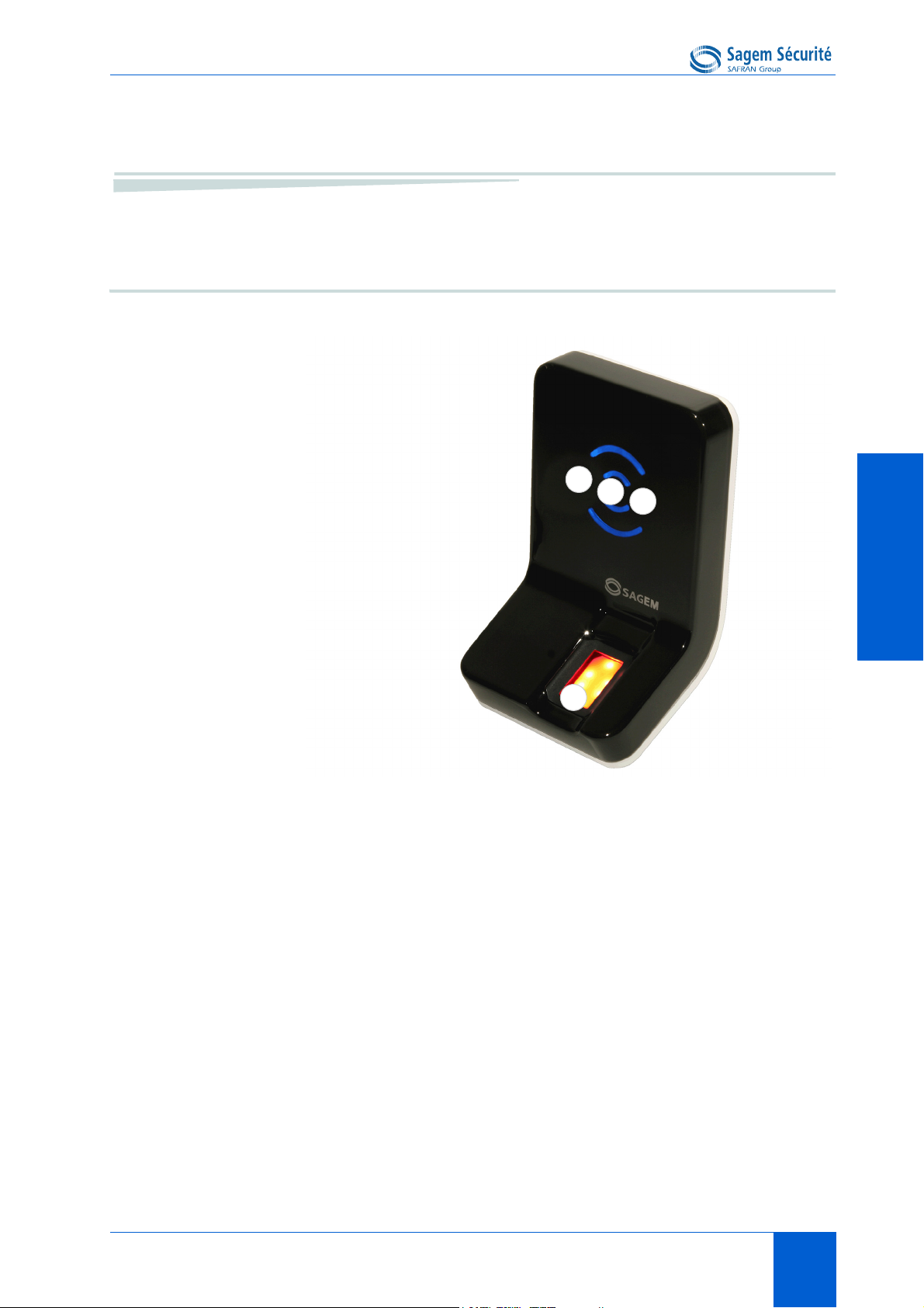
1. Interfaces presentation
User interface
TERMINAL PRESENTATIONTERMINAL PRESENTATIONTERMINAL PRESENTATIONTERMINAL PRESENTATIONTERMINAL PRESENTATIONTERMINAL PRESENTATION
Figure 2 • 1: MorphoAccess® J Series front view
®
The MorphoAccess
machine interface dedicated to access control based on fingerprint recognition:
• a high quality optical scanner to capture fingerprints (1),
• a multi-colour led (8 colors) (2),
• a multi-toned buzzer (3) ,
• on MorphoAccess
®
(4)
DESFire
DOCUMENT SSE-0000077399-01 - VERSION 1.0 - MAY 2010 9
S
AGEM SÉCURITÉ DOCUMENT - REPRODUCTION AND DISCLOSURE PROHIBITED
J Series terminals offer a simple and ergonomic man-
®
J-Dual, a contactless smartcard reader (MIFARE® and

Interfaces presentation MORPHOACCESS® J SERIES – User Guide
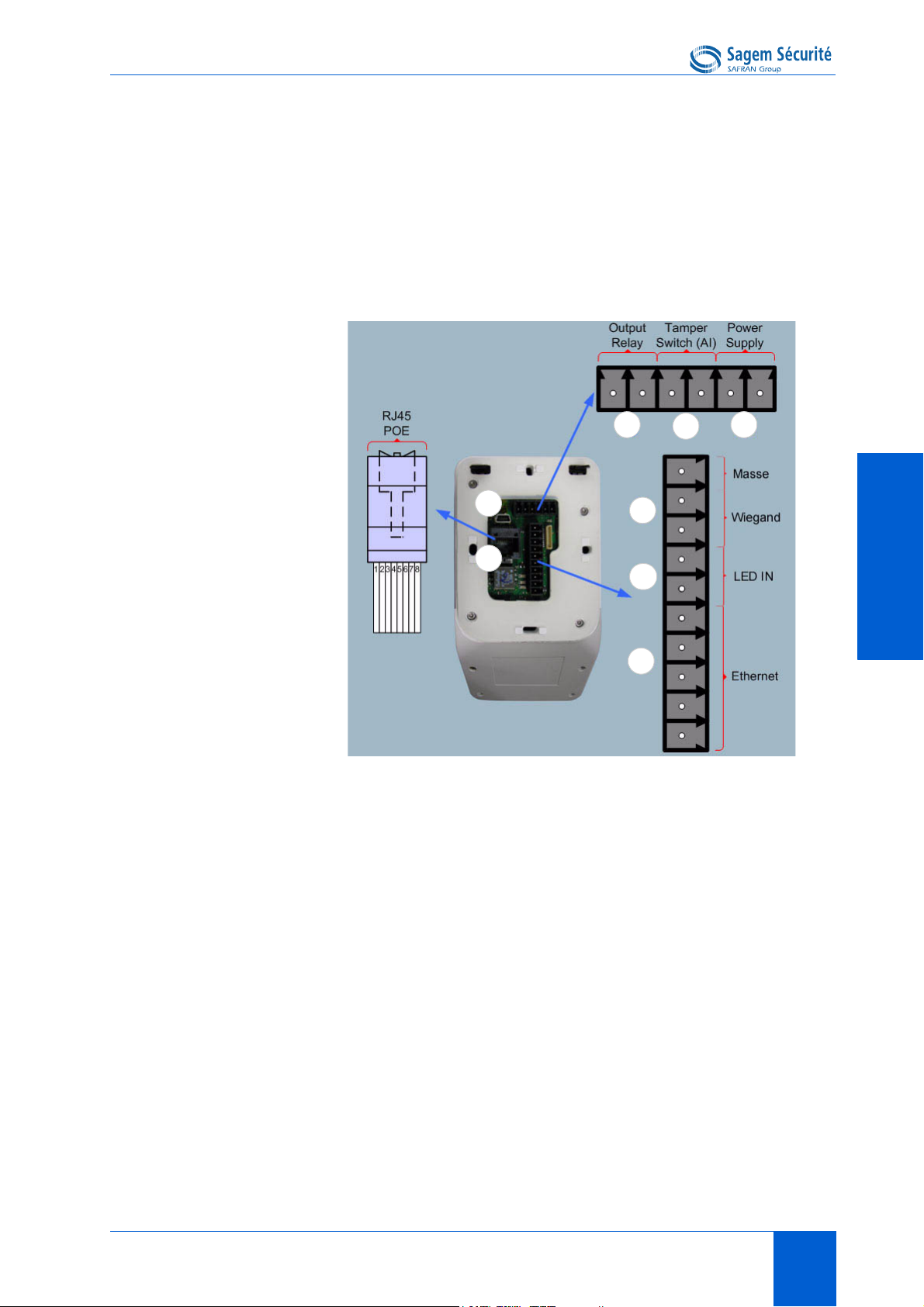
Power supply interface (see figures 2 • 2 and 2 • 3)
The terminal can be powered by two different ways:
• Either by the two wires +12V DC/GND (11)
• Or by the Power Over Ethernet function
®
Ethernet interface can be used to power the MorphoAccess
through POE (Power Over Ethernet) mode. According to the POE standard two
modes are available: power on data pins and power on dedicated pins.
®
On MorphoAccess
J Series terminal, POE can be used with RJ45 connector
(9) or with block connector (12). Modes are implemented as follows:
• POE through RJ45 connector (9): on data pins or on dedicated pins.
• POE through block connector (12): on data pins.
Use either one of these modes depending on POE implementation on your local
Ethernet network.
J Series terminal
A hardware reset button executes, when pressed, a power down/power up
sequence (14). This reset button is located under the removable smoked front
cover.
Administration interface (see figures 2 • 2 and 2 • 3)
The terminal can be configured through:
• A RJ45 Ethernet connector (LAN 10/100 Mbps), using TCP or SSL
protocol (9)
• A 5 wires Ethernet connection (LAN 10/100 Mbps), using TCP or SSL
protocol (12)
•A Wi-Fi
• a USB mass storage key for punctual and limited modifications, plugged,
when required, in the front USB port (13). This USB port is located under
the removable smoked front cover.
TM
adaptor plugged in the rear USB host port (10)
Access control devices and systems interface (see figure 2 • 2)
The terminal offers several interfaces dedicated to access control systems and
devices:
• the same Ethernet or Wi-Fi
UDP, TCP, or SSL protocol (9), or (12)
• one serial output port which supports these protocols : Wiegand /
10 DOCUMENT SSE-0000077399-01 - VERSION 1.0 - MAY 2010
S
AGEM SÉCURITÉ DOCUMENT - REPRODUCTION AND DISCLOSURE PROHIBITED
TM
link, as the one used for configuration, using
MORPHOACCESS® J SERIES – User Guide Interfaces presentation
5
7
11
8
6
12
9
10
DataClock / RS485 (5)
• two LED IN inputs (one for access granted, one for access denied), in an
Access Control System (6)
• a relay switch to directly command a physical device such as a door lock
(7),
• a tamper switch (8),
TERMINAL PRESENTATIONTERMINAL PRESENTATIONTERMINAL PRESENTATIONTERMINAL PRESENTATIONTERMINAL PRESENTATIONTERMINAL PRESENTATION
®
J Series rear view (connectors)
Figure 2 • 2: MorphoAccess
DOCUMENT SSE-0000077399-01 - VERSION 1.0 - MAY 2010 11
S
AGEM SÉCURITÉ DOCUMENT - REPRODUCTION AND DISCLOSURE PROHIBITED
Interfaces presentation MORPHOACCESS® J SERIES – User Guide
13
14
Figure 2 • 3: MorphoAccess® J Series with a USB mass storage key
®
Figure 2 • 4: MorphoAccess
The MorphoAccess
®
J Series Installation Guide describes precisely each
J Series with a Wi-FiTM adapter
interface and connection procedure.
12 DOCUMENT SSE-0000077399-01 - VERSION 1.0 - MAY 2010
S
AGEM SÉCURITÉ DOCUMENT - REPRODUCTION AND DISCLOSURE PROHIBITED

SECTION 3
TERMINAL
CONFIGURATION

MORPHOACCESS® J SERIES – User Guide
This chapter details how to configure the MorphoAccess® J Series terminal. A
parameter can be changed directly (using a USB mass storage key) on the
terminal or remotely through a network.
14 DOCUMENT SSE-0000077399-01 - VERSION 1.0 - MAY 2010
S
AGEM SÉCURITÉ DOCUMENT - REPRODUCTION AND DISCLOSURE PROHIBITED

MORPHOACCESS® J SERIES – User Guide Setting up the terminal IP address
1. Setting up the terminal IP address
The MorphoAccess® J Series terminal can run in stand alone mode but a TCP/
IP connection is required to download records in the terminal and to configure
its recognition mode.
It is possible to specify standard TCP parameters such as terminal network
address, network gateway or mask.
These parameters can be set using a USB mass storage key.
The complete procedure is decribed in section 2, Configuring a standalone
®
MorphoAccess®. Once connected to the network, the MorphoAccess
terminal can be configured using Configuration Tool application (for
example).
J Series
TERMINAL CONFIGURATIONTERMINAL CONFIGURATIONTERMINAL CONFIGURATIONTERMINAL CONFIGURATIONTERMINAL CONFIGURATIONTERMINAL CONFIGURATION
DOCUMENT SSE-0000077399-01 - VERSION 1.0 - MAY 2010 15
S
AGEM SÉCURITÉ DOCUMENT - REPRODUCTION AND DISCLOSURE PROHIBITED
Configuring a standalone MorphoAccess® MORPHOACCESS® J SERIES – User Guide
2. Configuring a standalone
MorphoAccess
"USB" key administration
MorphoAccess® J Series terminals have no keyboard, no screen. However it is
possible to change TCP/IP parameters without connecting the terminal on a
network. This operation only requires a standard USB Mass Storage key
(FAT16 formatted, 1 Gb maximum).
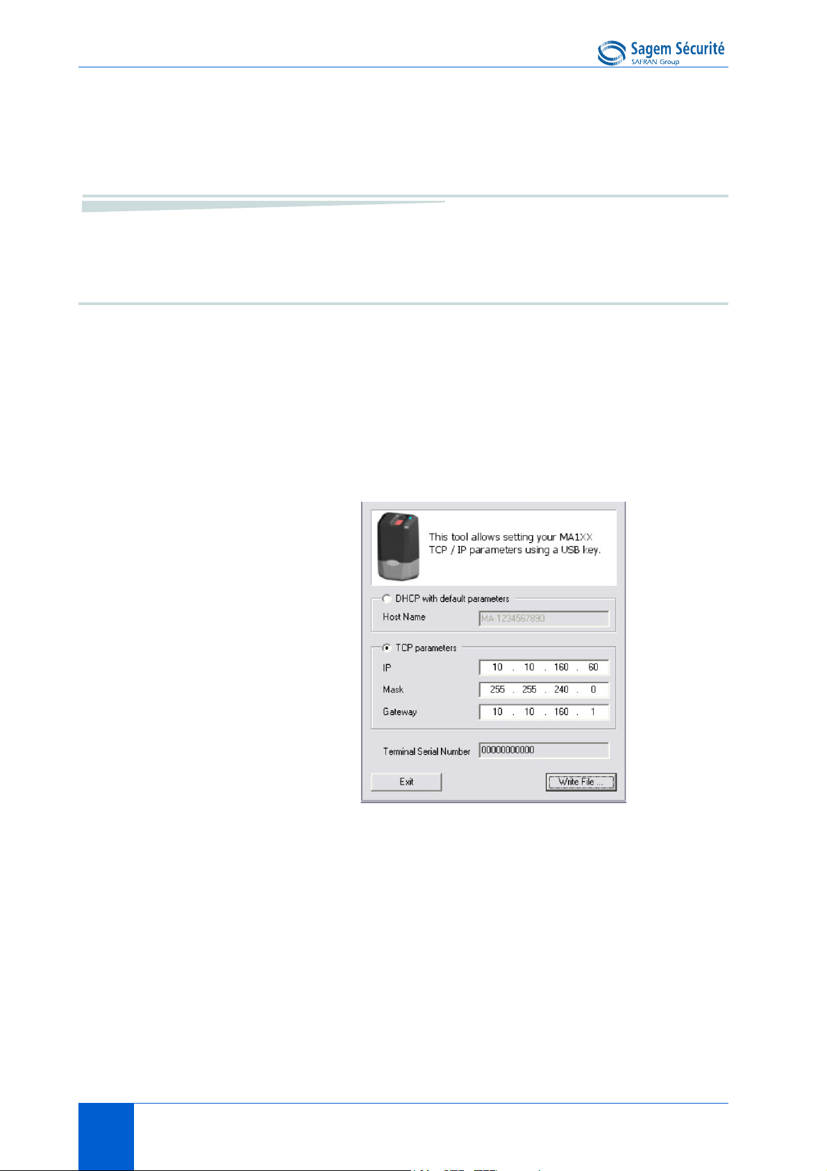
A decicated PC application, USB Network Configuration Tool, allows writing
these new parameters on the key.
®
Please refer to USB Network Tool User Guide.
Note about DHCP mode
®
The DNS server must be updated with MorphoAccess
users can communicate with the MorphoAccess
hostname. Please contact your network administrator.
16 DOCUMENT SSE-0000077399-01 - VERSION 1.0 - MAY 2010
S
AGEM SÉCURITÉ DOCUMENT - REPRODUCTION AND DISCLOSURE PROHIBITED
®
terminal names, so that
terminal using the terminal’s
MORPHOACCESS® J SERIES – User Guide Configuring a standalone MorphoAccess®
Principle
This feature is available to change network parameters (IP, address, mask and
gateway).
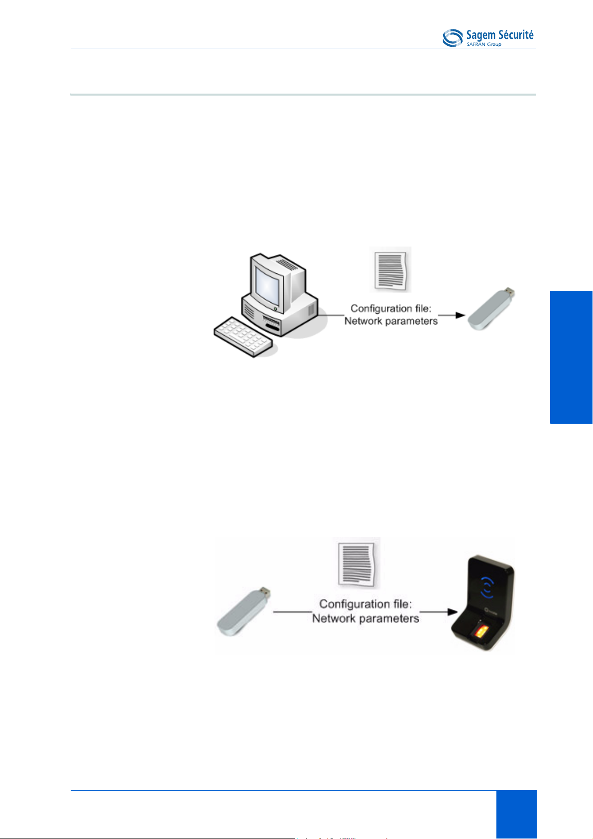
Store a file on a USB mass storage key
The administrator creates a configuration file on a PC using the USB Network
Configuration Tool. This configuration file contains new network
parameters. This file must be stored on a USB mass storage key.
TERMINAL CONFIGURATIONTERMINAL CONFIGURATIONTERMINAL CONFIGURATIONTERMINAL CONFIGURATIONTERMINAL CONFIGURATIONTERMINAL CONFIGURATION
Figure 3 • 1: Build a setting file on a USB mass storage key
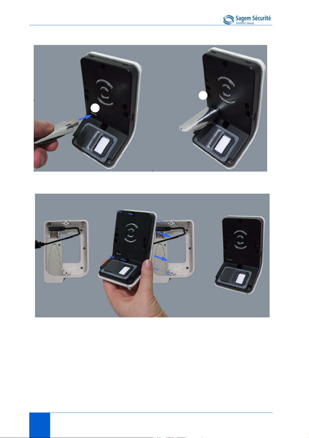
Apply changes on a standalone terminal
The front window of the MorphoAccess
®
must be removed to give access to
the USB Host Interface of the terminal. The terminal must be powered on.
When the USB mass storage key is inserted in the MorphoAccess
®
USB
interface, the configuration file is read: network parameters are applied.
Figure 3 • 2: Apply setting file to the MorphoAccess
®
At the end of the process, two medium-pitched «beeps» indicates that the USB
mass storage key can be removed.
Please refer to USB Network Configuration Tool User guide for more
information about this procedure.
DOCUMENT SSE-0000077399-01 - VERSION 1.0 - MAY 2010 17
S
AGEM SÉCURITÉ DOCUMENT - REPRODUCTION AND DISCLOSURE PROHIBITED

Understanding MorphoAccess® configuration parameters managementMORPHOACCESS® J SERIES – User Guide
3. Understanding MorphoAccess® configuration parameters management
Presentation
MorphoAccess® parameters (also named "configuration keys") are stored into
files organized in sections and values.
For example a file named "app.cfg" contains all the parameters defining the
main application settings.
Configuration organization
The application creates several files:
•app.cfg,
•adm.cfg,
•bio.cfg,
•net.cfg,
•gui.cfg
• wifi.cfg
The app.cfg file contains the application settings, adm.cfg contains
administration parameters, bio.cfg the biometric sensor settings, net.cfg the
Ethernet interface parameters, wifi.cfg some Wi-Fi™ parameters.
One file are reserved by the system to store factory settings:
fac.cfg.
18 DOCUMENT SSE-0000077399-01 - VERSION 1.0 - MAY 2010
S
AGEM SÉCURITÉ DOCUMENT - REPRODUCTION AND DISCLOSURE PROHIBITED
 Loading...