


INSTALLATION GUIDE
3 000 068 637 éd07 / 712
CONTENTS...........................................................................................................27
1. Safety instructions..................................................................................30
Keypad key assignments....................................................................................31
2. Daily use..................................................................................................31
3. Unpacking. Product contents................................................................33
4. Battery cover flap....................................................................................33
4.1.
Opening.....................................................................................................................33
4.2.
Closing.......................................................................................................................33
5. (De-)installation of SAM1 and SAM2 modules......................................34
6. CAM2 cover flap (secondary reader).....................................................34
6.1.
Opening.....................................................................................................................34
6.2.
Closing.......................................................................................................................34
7. (De-)installation of SAM3 and SAM4 (or SIM) modules .......................35
8. (De-)installation of MMC or SDCARD....................................................35
9. Secondary smart card reader ................................................................36
10. Installation...............................................................................................36
10.1. Installing EFT930 on its base ....................................................................................36
10.2. Base wire connections...............................................................................................37
10.3. Portable connections.................................................................................................43
10.4. Connecting the battery ..............................................................................................44
10.5. Charging the Battery..................................................................................................44
10.6. Adjusting the contrast................................................................................................45
10.7. Installing a roll of paper .............................................................................................46
11. Maintenance............................................................................................47
11.1. Operating the Portable in case of battery failure.......................................................47
11.2. Changing the Battery.................................................................................................47
11.3. Lithium Battery...........................................................................................................48
11.4. Cleaning the unit........................................................................................................48
12. Transport and Storage ...........................................................................48
13. Characteristics of the EFT930 ...............................................................49
14. Annex.......................................................................................................50
14.1. CE MARKING (CONFORMITY)................................................................................50
14.2. FCC Compliance .......................................................................................................51
15.2.1 EFT930G ...............................................................................................................51
15.2.2 EFT930W...............................................................................................................52
14.3. ATEX CONFORMITY................................................................................................53
14.4. BA-USB travel adapter ..............................................................................................53
Page 28 / 54
INSTALLATION GUIDE
FOREWORD
Thank you for choosing an EFT930.
INSTALLATION. We recommend you to read these instructions very carefully. They are included
with your EFT930 in order to explain its installation.
Particularly: when you receive a new terminal, the battery located in the portable is not connected.
See § "Installation, Connecting the battery" to realize this connection.
USE. Once it is installed and equipped with your application(s), you can use your EFT930 following
the instructions in the "user’s guides" specific to your application(s).
GUARANTEE AND SAFETY. In order to benefit from the guarantee on this equipment and in order
to follow the safety instructions, we ask you to use only SAGEM Monetel approved batteries and to
entrust disassembly procedures solely to an authorized person.
The manufacturer cannot be held liable for any unauthorized handling of an EFT930 terminal.
Telephone emergency, hanging up:
You have an urgent call to make, but EFT930 is on your telephone line.
In order to get a dial tone, ...
Place the handset in the hang up position and:
press the red key (= CANCEL) ;
or remove the portable terminal from its base ;
or disconnect the EFT930 telephone connector from the telephone wall socket,
and place the telephone connector into the telephone wall socket.
You will get a dial tone within 6 seconds.
Page 29 / 54 3 000 068 637 éd07 / 712
INSTALLATION GUIDE
3 000 068 637 éd07 / 712
1. SAFETY INSTRUCTIONS
A- In order to power down the EFT930 base :
disconnect the EFT930 power supply block from the electric power supply network.
B- Lithium battery and battery
The EFT930 is fitted with a lithium battery which is not operator accessible. Only a
qualified technician may be authorized to open the unit and service this component.
Refer to the paragraph entitled "Lithium battery" in the "Maintenance" chapter.
The EFT930 is fitted with a Sagem Monetel battery especially designed for this terminal.
• Only use the appropriate chargers and batteries listed in the manufacturer’s catalogue.
• The battery does not contain any components that can be changed by you.
• Do not short-circuit.
• Do not attempt to open the battery case.
• Used batteries must be collected at the appropriates sites.
Warning notice for Lithium-Ion batteries:
There is a risk of explosion if the battery is incorrectly replaced and disposed of in fire
C- Electrical power supply network
Provide an inlet connector for the electrical power supply network that meets the following
points:
• Connector installed near the equipment and easily accessible;
• Connector meeting standards and regulations in force in the country of use;
For Pluggable Equipment Type A, the protection in the installation is assumed
to be 20A.
D- Telephone network
Provide an inlet connector for the telephone in compliance with standards and regulations in
force in the country of use.
E- Cover flap for battery and SAM1 and SAM2 reader
The cover flap for batteries and for the SAM1and SAM2 reader, located underneath the
terminal, must be in place during the normal operation of the terminal. See sections
"(De)Installation of SAM1 and Sam2 modules" and "Connecting the battery".
F- Cover flap for CAM2, SAM3 and SAM4 (or SIM) reader
The cover flap for CAM2, SAM3 and SAM4 (or SIM), located on the underside of the terminal
must be in place during normal operation of the terminal. See chapter "(De)Installation of
SAM3 and Sam4 (or SIM) modules".
G- Warning – special cases of radio handset (EFT930G and EFT930B)
Safety in airplanes
When in an airplane, your handset must be switched of by removing the battery pack.
Its use is illegal; non-compliance with these safety rules may result in legal proceedings
and/or a ban on later access to cellular network services.
Explosion hazard areas
Regulations restrict the use of radio equipment in chemicals plants, fuel depots and any site
where blasting is carried out. You are urged to comply with these regulations. The terminal
shall be protected by a specific cover enabling use in proximity to a fuel pump.
Electronic health appliances
Your handset is a radio transmitter witch may eventually interfere with health appliances, for
example hearing aids, pacemaker, equipment hospital environments etc.
Your doctor or the equipment manufacturer will be able to provide you with appropriate advi
Page 30 / 54
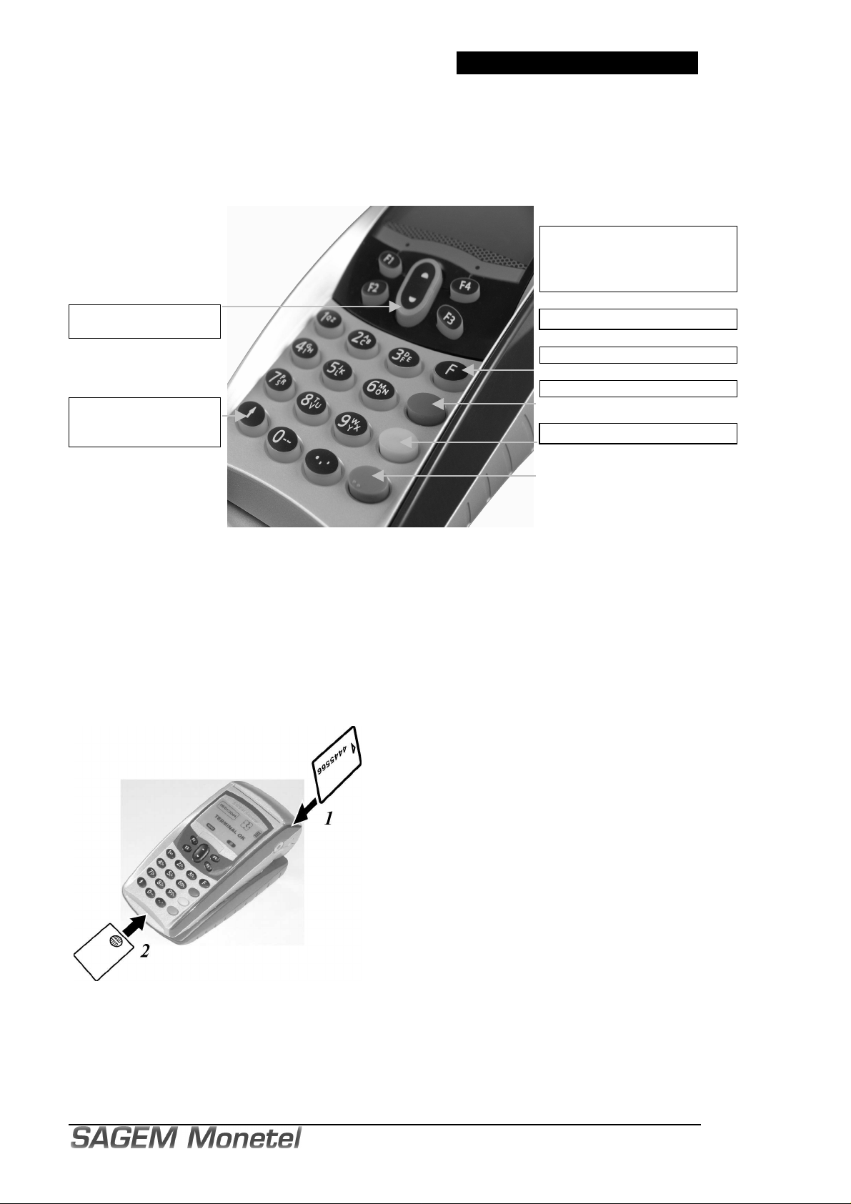
KEYPAD KEY ASSIGNMENTS
upper edge of card (defined with respect to text
Navigate up and down
keypad
START
PAPER FEED Key
or
INSTALLATION GUIDE
The 4 keys marked
"F1, F2, F3, F4"
are interactive keys for
screen-operator dialog.
Function key: F
Cancel key: Red
Correction key: Yellow
Validation key: Green
2. DAILY USE
Card insertion and reading direction
Reading the magnetic stripe (on a swipe or chip
card):
• Position the card as follows:
- front side towards the right (Magnetic stripe is
on opposite side).
reading direction) set at reader lead-in.
• Run the card by hand through the reader.
(arrow 1).
Inserting a chip card :
Chip facing up (arrow 2)
Page 31 / 54 3 000 068 637 éd07 / 712

INSTALLATION GUIDE
3 000 068 637 éd07 / 712
Using the base
Once installed, the base is designed to remain on constantly and connected to the telephone
network.
The telephone line should not be shared.
The portable may be placed back in its base after each transaction.
It must be placed on its base in the following cases:
• telephone network using: authorization request, remote collection, downloading;
• check processing, if the base is connected to a check reader.
Battery autonomy
Removed from its socket, the Portable can perform up to 300 transactions at 20°C, provided
completely charged batteries are used.
Stopping the Portable, Start Key
Removed from its socket, after it has been used and if its battery is empty, the terminal
automatically shuts off. The screen is turned off.
It may also be forced stopped by pressing simultaneously "Point" and "Yellow" keys during one
second.
In order to restart the Portable, press the key on the keyboard.
Precautions when using Heat-Sensitized Paper
As the ticket may deteriorate in the event of improper storage, the following must be avoided:
• Storage in areas that are hot and humid (close to a heater/cooling unit, degree of humidity
greater than 85%),
• Long-term exposure to sunlight or ultraviolet rays,
• Contact with organic solvents (solvent-based adhesives),
• Direct contact with material containing softening (plasticizing) agents (envelopes or clear
plastic folders made of PVC),
• Direct contact with whiteprint paper,
• Direct contact with water,
• Rubbing or pressing the paper too strongly.
Page 32 / 54
INSTALLATION GUIDE
3. UNPACKING. PRODUCT CONTENTS
Carefully preserve the packaging of the EFT930.
It must be re-used whenever the terminal is shipped.
Packaging contains:
• PORTABLE itself, equipped with:
- its battery pack not connected,
- its paper roll;
• Base receiving the PORTABLE;
• Detachable power supply unit;
(the power supply unit delivered with your terminal is specially designed for it. Do not
use any other power supply.)
The use of a power supply having apparently similar voltage/current characteristics may, in
spite of it, damage your terminal;
• Telephone cable;
• Installation manual.
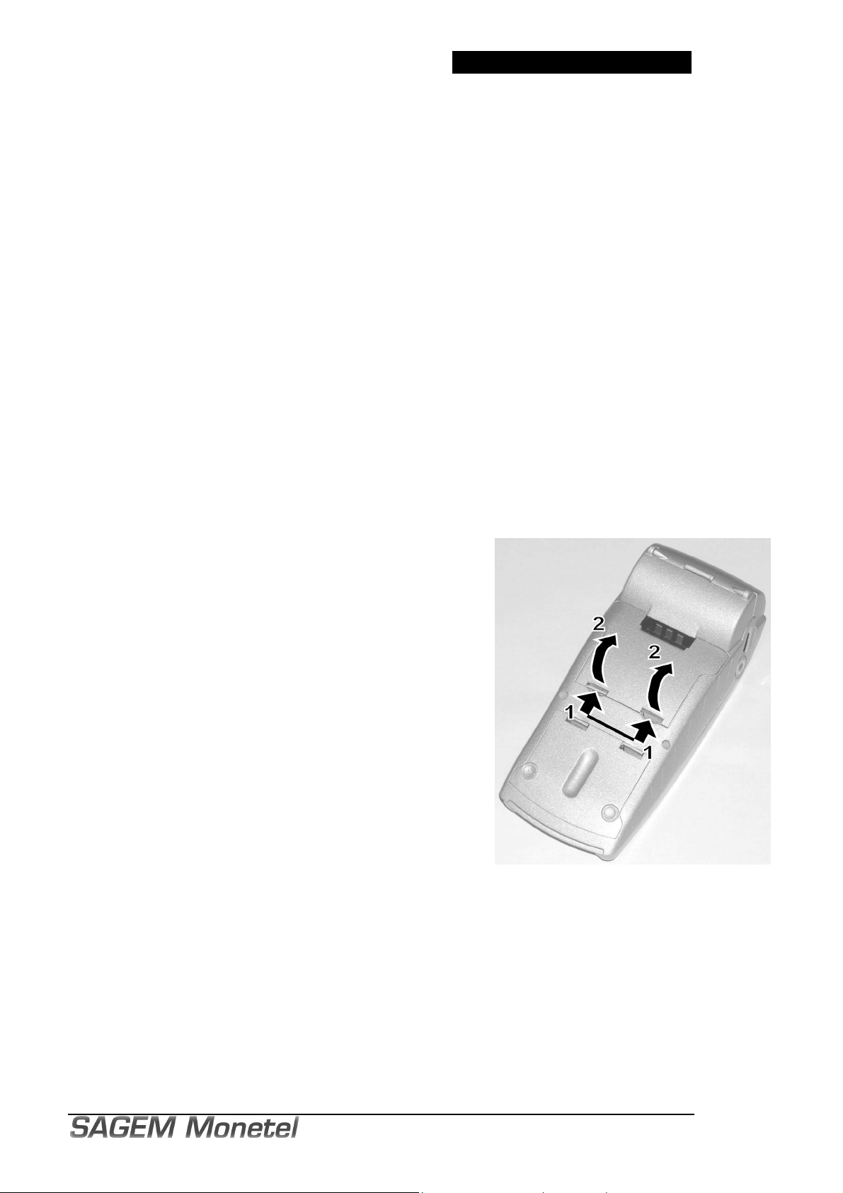
4. BATTERY COVER FLAP
The battery cover flap is located under the portable.
Caution :
Switch off the machine before opening the cover.
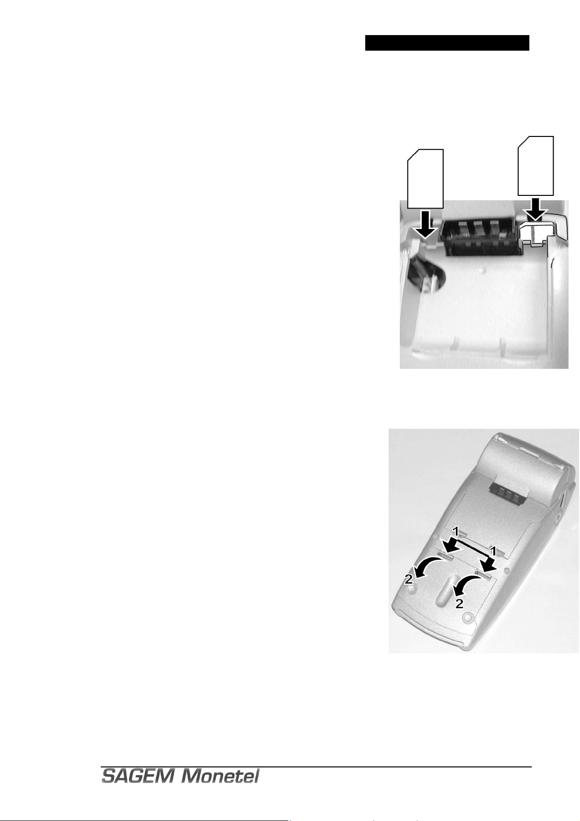
4.1. OPENING
• Turn the PORTABLE over on the table with the bottom side
facing up (figure opposite).
• Unclip the cover flap by pushing on the clips with your nails in
the direction of the arrow 1 as shown opposite.
• Lift the cover flap on the clips side (arrow 2), disengage the
two rear limiting tabs from underneath the terminal housing
and remove the cover flap.
4.2. CLOSING
To close up the device, carry out the above operations in the reverse order.
• Engage the two rear limiting tabs of the flap cover under the terminal housing;
• Fold cover downwards to clip it on.
If a SAM stops the cover flap from closing, check the direction of its insertion.
• Make sure the clips are totally engaged under the housing by pushing them manually.
Page 33 / 54 3 000 068 637 éd07 / 712
INSTALLATION GUIDE
3 000 068 637 éd07 / 712
5. (DE-)INSTALLATION OF SAM1 AND SAM2
MODULES
Caution :
Switch off the machine before opening the cover.
• Open the battery compartment cover flap (See § "Battery
cover flap"):
you can read the location mark of SAM1 and SAM2 engraved
in the lower housing.
• When introducing a SAM in its slot, be sure to put the cut
corner as indicated on the figure opposite.
• Close the flap cover.
Removing
Handy tip: use a piece of adhesive tape to grip the SAM to make
withdrawal easier.
SAM 1 SAM2
6. CAM2 COVER FLAP
(SECONDARY READER)
CAM2 cover flap is located under the portable
Caution :
Switch off the machine before opening the cover.
6.1. OPENING
• Turn the PORTABLE over on the table with the bottom side
facing up (figure opposite).
• Unclip the cover flap by pushing simultaneously the clips with
your nails in the direction of the arrows 1 as shown opposite.
• Lift the cover flap on the clips side (arrows 2) and remove the
cover flap.
6.2. CLOSING
To close up the device, carry out the above operations in the
reverse order.
• Engage the front of the flap cover under the terminal
housing.
• Fold cover backwards to clip it on.
• Make sure the clips are totally engaged under the housing by pushing them manually.
Page 34 / 54
INSTALLATION GUIDE
SAM3
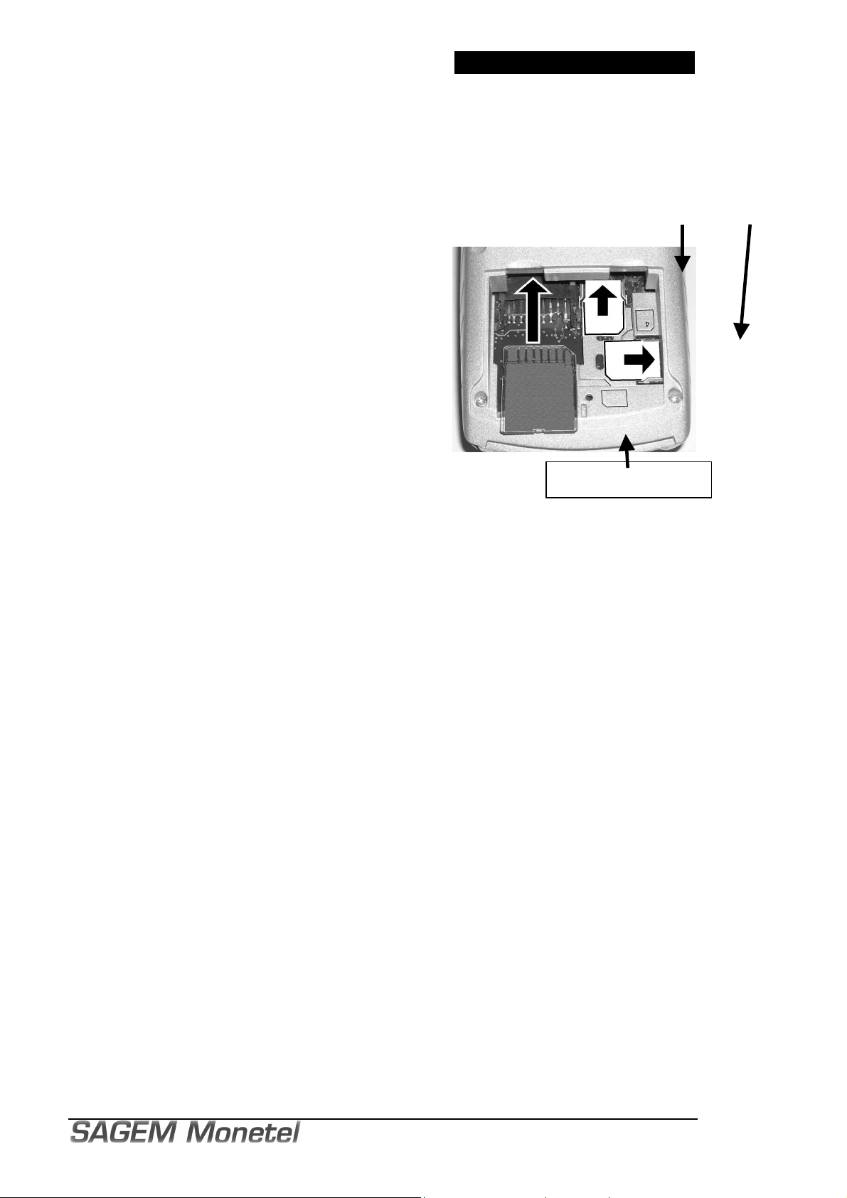
7. (DE-)INSTALLATION OF SAM3 AND SAM4
(OR SIM) MODULES
The SAM3 and SAM4 (or SIM) modules are installed under the CAM2 cover flap.
The location 4 may be used by a SAM or a SIM.
Caution :
Switch off the machine before opening the cover.
• Open the CAM2 cover flap (See § "CAM2 cover flap"):
you can read the location mark of SAM3 and SAM4
engraved in the lower housing.
• When introducing a SAM in its slot, be sure to put the
cut corner as indicated on the figure opposite.
The position of the cut corner is also engraved on the
lower housing.
• Close the flap cover.
MMC or SDCARD
SAM4
8. (DE-)INSTALLATION OF MMC OR SDCARD
To gain access to the MMC or to the SDCARD connector, open the CAM2 cover flap.
Caution:
Switch off the machine before opening the cover.
To install a MMC or a SDCARD (figure above):
• Open the CAM2 cover flap.
• Insert the MMC or a SDCARD fully home into the connector slot shown by the arrow in the
figure above. Be sure to put the cut corner as indicated on the figure above.
• Close the CAM2 cover flap.
To remove a MMC or a SDCARD:
• Open the CAM2 cover flap.
• Withdraw the MMC or a SDCARD.
• Close the CAM2 cover flap.
Page 35 / 54 3 000 068 637 éd07 / 712
INSTALLATION GUIDE
3 000 068 637 éd07 / 712
9. SECONDARY SMART CARD READER
The secondary smart card reader is also called "CAM2 reader".
To gain access to the secondary smart card reader, open the CAM2 cover flap.
Caution :
Switch off the machine before opening the cover.
To insert a smart card into the CAM2 reader:
• Open the CAM2 cover flap.
• Position the smart card with the chip in the position
shown in figure opposite:
- chip forward, but not visible (facing down)
- magnetic stripe visible (facing up).
• Insert the card fully home into the slot.
• Close the CAM2 cover flap.
To remove a smart card from the CAM2 reader:
• Open the CAM2 cover flap.
• Withdraw the smart card
• Close the CAM2 cover flap.
10. INSTALLATION
10.1. INSTALLING EFT930 ON ITS BASE
Place the EFT930 between the flanges on its
base so that the contacts of the EFT930 engage
on the contacts provided on the base (figure
opposite).
Page 36 / 54

INSTALLATION GUIDE
10.2. BASE WIRE CONNECTIONS
Reminder of safety procedures:
Select an electrical socket that complies with the general safety instruction given in chapter 1 of
this present document.
Charger base (for EFT930G or EFT930W without modem).
Marking
The external appearance of the charger base is identical to that of the P base. However, with the
exception of the supply jack, the visible connectors are not functional.
Rear view of base
E = Mains power supply network socket F = Power supply unit
H = Power supply input G, J, I = vacant
Page 37 / 54 3 000 068 637 éd07 / 712

INSTALLATION GUIDE
3 000 068 637 éd07 / 712
P base (base for EFT930P or EFT930G / EFT930W with modem)
Marking
Rear view of base
A = possible telephone handset B = telephone connector (country specific)
C = connection to the telephone network D = telephone network socket
E = mains power socket F = power adapter
G = telephone network port H = power input
I = serial port (cash register, local loading tool,
etc.)
J = telephone handset output
Perform the following operations:
− Connect the base to the telephone network
• Connect telephone plug C, equipped if necessary with user country specific
telephone plug, to the telephone network D.
• Connect the other end of the wire to the base (socket G),
• Connect the mains power supply wire to the base (socket H),.
• If necessary, connect the telephone A.
(Telephone A is not required for the terminal to operate).
- France: plug B to the telephone network D through the piggyback plug
- other countries: telephone connected to the base through the socket J (RJ-type
connector).
− Connect power supply block F to the mains electrical socket E.
Socket G (=socket J): TNV-3 circuit: Telecommunication Network Voltage, as per safety
standard EN 60950.
Socket I: SELV circuit: Since these links are Safety Extra Low Voltage circuits, they must
be interconnected to units which have interfaces powered by the same type of circuits.
Connecting is to be made when the terminal is off.
Page 38 / 54

INSTALLATION GUIDE
G
J
I
H
P base (base for EFT930P or EFT930G / EFT930W with modem)
Marking
Rear view of base
USB
A = possible telephone handset B = telephone connector (country specific)
C = connection to the telephone network D = telephone network socket
E = mains power socket F = power adapter
G = telephone network port H = power input
I = serial port (cash register, local loading tool,
etc.)
J = telephone handset output
Perform the following operations:
• Connect the base to the telephone network:
- Connect telephone plug C, possibly in conjunction with a closing relay satisfying the
standards applicable in the country of use, to the telephone network D.
Connect the other end of the cable to socket G on the base.
- If present, connect telephone A (the presence of telephone A is not required for the
terminal to function)
- France: connect B to the telephone network D via the stackable socket
• Connect the power supply unit F to the mains power supply network socket.
Socket G : TNV-3 circuit: Telecommunications Network Voltage, in accordance with safety
standard EN 60950.
Sockets I and J : as these connections are for ELSV circuits (extra low safety voltage), they shall
be interconnected to equipment with interfaces supplied by circuits of the same type.
The connections will be made with the device switched off.
Page 39 / 54 3 000 068 637 éd07 / 712

3 000 068 637 éd07 / 712
G
J
I
H
M
K
B base with modem (for EFT930B with modem)
Marking
INSTALLATION GUIDE
L
A = possible telephone handset B = telephone connector (country specific)
C = connection to the telephone network D = telephone network socket
E = mains power socket F = power adapter
G = telephone network port H = power input
I = serial port (cash register, local loading tool,
etc.)
K = PC L = USB cable
M = USB link
J = telephone handset output
Page 40 / 54

INSTALLATION GUIDE
G
J
H
M
K
B base with 2 COM modem (for EFT930B with modem)
Marking
A = possible telephone handset B = telephone connector (country specific)
L
C = connection to the telephone network D = telephone network socket
E = mains power socket F = power adapter
G = telephone network port H = power input
I = serial port (cash register, local loading
tool, etc.)
K = PC L = USB cable
M = USB link
J = 2nd serial connection
Page 41 / 54 3 000 068 637 éd07 / 712

INSTALLATION GUIDE
3 000 068 637 éd07 / 712
H
M
G
J
I
Base B Ethernet (pour EFT930B Ethernet)
Marking
E = mains power supply network socket F = power supply unit
N
L
K
G = 2nd serial connection (4-point connector) H = power supply input
I = 1st serial connection (cash register, local loading
tool, etc.)
K = PC L = USB cable
M = USB connection N = Ethernet cable
J = Ethernet connection
Page 42 / 54

10.3. PORTABLE CONNECTIONS
Host Mini-USB
connector
INSTALLATION GUIDE
Slave Mini-USB
connector
(for travel BA–USB
adapter*, PC, etc.)
* Travel BA–USB adapter is an EFT930 accessory (See appendix).
Page 43 / 54 3 000 068 637 éd07 / 712

3 000 068 637 éd07 / 712
Turn the PORTABLE over on the table with the
bottom side facing up and remove the cover
pack connector foolproofing
ctor located under the
Plug the battery pack connector on the board
according to the connector locating system
Feel the
Place the battery pack in its compartment
10.4. CONNECTING THE BATTERY
The battery pack is contained in the packaging carton.
On a new device, the battery pack is not connected.
1-
flap (See §" Battery cover flap")
2- Locate the battery
and the board conne
battery compartment (figure 1).
3-
and the wire colors (figure 1).
locking.
4-
(figure 2).
5- Close the battery compartment cover flap.
10.5. CHARGING THE BATTERY
When is the battery to be charged?
INSTALLATION GUIDE
= red wire
fig.1
fig.2
• On initial start up, charge the battery for 16 hours under the environmental conditions
stated above.
• When used daily the PORTABLE will recharge its batteries each time it is placed on its
base.
Charging is automatic.
A completly discharged battery requires 8 hours for a complete recharge.
Where is the battery to be charged?
• The environment in which the charge takes place influences battery lifetime and autonomy
(number of transactions out of base).
The optimal conditions are as follows:
- charging away from any external heat source (radiator, sun, enclosed area…);
- the optimal temperature is between +15°C and +25°C.
Page 44 / 54

INSTALLATION GUIDE
How is the battery to be charged?
Using the base
• Place the PORTABLE on its base.
• Check to see if the electrical plug symbol is displayed on the portable screen and if
the battery symbol is moving (=battery charging).
Using the slave mini-USB connector of the portable
(The portable is out of its base)
• Connect the power supply unit to the BA-USB adapter. See §"Appendix, BA-USB travel
adapter".
• Connect this assembly to the slave mini-USB connector located on the side of the
portable. See §"Portable connections".
• Connect the power supply unit to the mains.
• Check to see if the battery symbol is moving (=battery charging).
10.6. ADJUSTING THE CONTRAST
If you wish to modify the contrast of the characters displayed on the screen, simply press and hold
the "Point" and " " or "Point" and " " keys as long as necessary to obtain a satisfactory contrast.
Page 45 / 54 3 000 068 637 éd07 / 712

INSTALLATION GUIDE
3 000 068 637 éd07 / 712
Catch
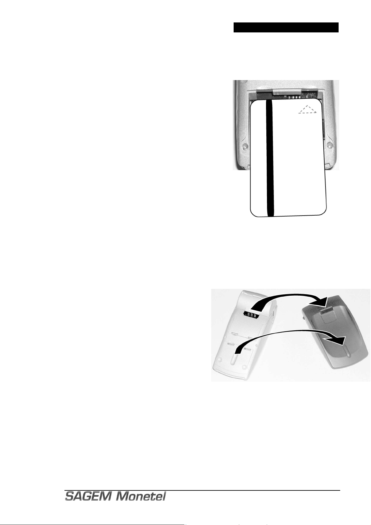
10.7. INSTALLING A ROLL OF PAPER
Warning: Use only paper approved by SAGEM Monetel.
Use of unsuitable paper is likely to damage the printer of your terminal.
Roll diameter: 40 mm.
1- If you are inserting a new roll, tear off the first
length (one complete turn).
2- Open the paper recess cover plate (figure 1a) as
follows:
• Raise the catch located on the rear of the
EFT930;
• Grip the cover plate and tilt it down from the rear
of the terminal. (Figure 1b)
3- Insert the roll of paper in its housing following the
direction of movement shown in figure 2.
4- Pull the paper up to the top of the terminal (figure 2).
Hold it in this position.
5- Push up the cover plate fully home. (Figure 3).
6- Press simultaneously on both upper corners of the
paper flap (arrows on figure 3) until it clips into
position and holds the paper.
The EFT930 terminal is now ready for use.
Handy tip: the amount of paper remaining can be
checked by looking through the left side hole.
Once installed, continue EFT930 setup by following
the instructions in the application manuals.
fig.1a
fig.1b
fig.2
fig.3
Page 46 / 54

INSTALLATION GUIDE
11. MAINTENANCE
11.1. OPERATING THE PORTABLE IN CASE OF BATTERY FAILURE
If the battery life of the terminal becomes very low, or when the print speed is significantly reduced,
the battery should be deep discharged before being completely recharged again. This operation is
performed using the relevant menu in Telium manager; it must not be performed more than once a
month.
Battery failure can be identified as follows:
• nothing is displayed on the screen, or
• the screen displays the message BATTERY ABSENT when EFT930 is placed on its base, or
• even after prolonged charging and following a “deep” discharge, the terminal has only a very
limited battery life.
The battery must be changed.
In the absence of a battery, the applications present in the device can be initialised by placing the
terminal on its base. However, transactions cannot be performed in these conditions.
11.2. CHANGING THE BATTERY
It is imperative to use a battery authorized by SAGEM Monetel.
There is danger of explosion if battery used is not approved by SAGEM Monetel.
• Remove the portable from its base.
• Turn it off by pressing simultaneously the "Point" key and the "yellow" key during about one
second.
• Remove the cover of the battery housing (see § "Battery cover flap".
• Lift battery and remove it from its housing.
• Carefully disconnect battery, following the
instructions below.
a) Unlock the connector by pressing the locking
mechanism as indicated by F1 arrow while pulling
wires (arrow F2), so as to disconnect the connector.
Release traction on it as soon as the connector
comes unclipped.
b) Finish extracting connector by tilting it slightly
(arrow F3) so as to bring it away from the housing of
the terminal.
• Inform the terminal that its battery has been
changed. Do this by starting the terminal without battery and fitting it on its base.
• Connect and install the new battery by following the instructions in § "Connecting the
Battery".
• Close the battery cover flap and charge the battery. See § "Charging the Battery".
• In order to preserve the environment, dispose of used batteries in compliance with current
recycling legislation in the country of use.
• If the terminal is to be stored for a long time (more than two months), remove the battery
from the terminal.
Simply powering up enables the terminal to memorize that there is no battery; it will then
perform correctly with the future battery.
Page 47 / 54 3 000 068 637 éd07 / 712

INSTALLATION GUIDE
3 000 068 637 éd07 / 712
11.3. LITHIUM BATTERY
For the attention of maintenance departments:
Warning: this equipment is provided with a lithium battery. There is a risk of explosion if this
battery is incorrectly replaced. Replace using only a battery recommended by the
manufacturer.
Dispose of used batteries according to current recycling legislation.
Only qualified personnel can be authorized to service this component.
11.4. CLEANING THE UNIT
• Unplug all the wires from the base.
• Use a soft cloth
and the base. Do not clean the contacts.
• The terminal-base connection may become contaminated by dust, and your unit could then
show the following faults:
VERY SLIGHTLY
dampened with soapy water to clean the Portable hoods
- Even when put on the base, the terminal does not recharge or charge.
- The terminal does not detect the telephone line.
You should then clean the electrical contacts of the terminal and base connections:
- Clean off all visible dust with a dry cloth.
- Then, dip a cotton bud in domestic alcohol and squeeze it slightly damp (liquid must
not penetrate inside the equipment). Rub the cotton bud on the contact surfaces
several times to remove all particles adhering to them and/or electrostatically charged
particles (contamination can be difficult to see with the naked eye).
- Return the terminal to use.
12. TRANSPORT AND STORAGE
• Use the original packing material for any unit transport or storage.
• Disconnect the battery whenever the portable is not to be used for a period exceeding one
month.
The method to disconnect the battery is indicated in the § "Changing the battery".
Page 48 / 54

INSTALLATION GUIDE
13. CHARACTERISTICS OF THE EFT930
Portable physical characteristics
Weight : between 360 g and 410 g, according to the options, without
paper roll
Dimensions : 180 x 80 x 55 mm (L x W x H)
Base physical characteristics
Weight : 120 g
Dimensions : 153 x 87 x 33 mm (L x W x H)
Telephone cable length : 3 m
Power supply cable length : 3 m
Power supply block : 100 g
Standards
See in appendix the "EC" standard compliance marking
Operating conditions
Class II
Electrical network : 100-240VAC; 50-60 Hz
Consumption : 150 mA
Power supply block : 2 pole socket 2,5 A
Ambient temperature : +5°C to +45°C
Maximum relative humidity : 85% at +40°C
Serie link : level RS 232 / V28
Mini-USB A serie link : 100mA max
Mini-USB B serie link
Storage conditions
Storage temperature : -20°C to +55°C
Maximum relative humidity : 85% at +55°C
Paper References No.
In order to benefit from the full product warranty, you must use thermal paper
authorized by SAGEM Monetel.
Diameter of paper rolls: 40 mm.
Page 49 / 54 3 000 068 637 éd07 / 712

INSTALLATION GUIDE
3 000 068 637 éd07 / 712
14. ANNEX
14.1. CE MARKING (CONFORMITY)
The CE marking indicates that product EFT930P/G/B complies with the requirements of European
Directive 1999/5/EC of 9 March 1999 on Radio and Telecommunications Terminal Equipment for:
- the protection of the health and the safety of the user and any other person.
- the protection requirements with respect to electromagnetic compatibility.
and complies with the following harmonised standards:
EFT930P
EN 60950-1 /2001 According to 73/23/EEC (Low Voltage Directive)
EN 55022 A2 /2003 According to 89/336/EEC (EMC Directive)
EN 55024 A2 /2003 According to 89/336/EEC (EMC Directive)
EFT930G
EN 60950-1 /12-2001 According to 73/23/EEC (Low Voltage Directive)
EN 301489-7 /08-2000 According to 89/336/EEC (EMC Directive)
EN 301 511 /12-2000 According to 1999/5/EC (R&TTE Directive)
EN 50360 /07-2001 According to 1999/519/EEC (R&TTE Directive)
EFT930B
EN 60950-1 /12-2001 According to 73/23/EEC (Low Voltage Directive)
EN 301489-1/7 /08-2000 According to 89/336/EEC (EMC Directive)
EN 300 328 v1.4.2 /12-2000 According to 1999/5/EC (R&TTE Directive)
EFT930W
N 60950-1 /12-2001 According to 73/23/EEC (Low Voltage Directive)
EN 301489-1/7 /08-2000 According to 89/336/EEC (EMC Directive)
EN 300 328 v1.4.2 /12-2000 According to 1999/5/EC (R&TTE Directive)
And, for the whole range, complies with the European approval specification on connecting
terminals with DTMF dialling to the public switched telephone network (Council Decision
1998/482/EC, Council Decision 1999/303/EC):
TS 103021-1/2/3 /09-2003
TR 103000-1/2/3/4 /06-2003
ES 201187 /03-1999
Page 50 / 54

INSTALLATION GUIDE
14.2. FCC COMPLIANCE
15.2.1 EFT930G
The FCC ID for this model is : TTSEFT930
The EFT930G complies with basic requirements from the FCC concerning RF equipment with
respect to the requirements for Personal mobile radio services in the CFR47,
Conforms to the following standards:
- FCC Part 24E (PCS 1900 frequency band),
- FCC Part 22H (GSM 850 frequency band),
- FCC Part 15 Subpart B
Certification information (SAR)
The model wireless equipment meets the government's requirements for exposure to radio waves.
Your wireless equipment is a radio transmitter and receiver. It is designed and manufactured not to
exceed limits for exposure to radio frequency (RF) energy set by the Federal Communications
Commission (FCC) of the U.S. Government and by the Canadian regulatory authorities. These
limits are part of comprehensive guidelines and establish permitted levels of RF energy for the
general population. The guidelines are based on standards that were developed by independent
scientific organizations through periodic and thorough evaluation of scientific studies. The
standards include a substantial safety margin designed to assure the safety of all persons,
regardless of age or health.
The exposure standard for wireless equipment employs a unit of measurement known as the
Specific Absorption Rate, or SAR. The SAR limit set by the FCC and by the Canadian regulatory
authorities is 1.6 W/kg.
1. Tests for SAR are conducted using standard operating positions accepted by the FCC and by
Industry Canada with the phone transmitting at its highest certified power level in all tested
frequency bands. Although the SAR is determined at the highest certified power level, the actual
SAR level of the equipment while operating can be well below the maximum value. This is because
the equipment is designed to operate at multiple power levels so as to use only the power required
to reach the network. In general, the closer you are to a wireless base station, the lower the power
output.
Before a equipment model is available for sale to the public in the U.S. and Canada, it must be
tested and certified to the FCC and Industry Canada that it does not exceed the limit established by
each government for safe exposure. The tests are performed in positions and locations (e.g., at the
ear and worn on the body) reported to the FCC and available for review by Industry Canada. The
highest SAR value for this equipment when tested for use when worn on the body is 0.711 W/kg.
(Body-worn measurements differ among phone models, depending upon available accessories and
regulatory requirements).
2. While there may be differences between the SAR levels of various terminal and at various
positions, they all meet the governmental requirements for safe exposure.
The SAR values found for the EFT930G GSM/GPRS Point of sale terminal are below the maximum
recommended levels of 1.6 W/Kg as averaged over any 1 g tissue according to the FCC rule
§2.1093, the ANSI/IEEE C 95.1:1999, the NCRP Report Number 86 for uncontrolled environment,
according to the Health Canada’s Safety Code 6 and the Industry Canada Radio Standards
Specification RSS-102 for General Population/Uncontrolled exposure.
For body worn operation, this phone has been tested and meets FCC RF exposure guidelines
when used with an accessory that contains no metal and that positions the device a minimum of 0
mm from the body.
Page 51 / 54 3 000 068 637 éd07 / 712

INSTALLATION GUIDE
3 000 068 637 éd07 / 712
15.2.2 EFT930W
The FCC ID for this model is : TTSEFT930W
• Statement required by 15.19 and RSS210
This device complies with Part 15 of the FCC Rules and with RSS-210 of Industry Canada.
Operation is subject to the following two conditions:
(1) this device may not cause harmful interference, and
(2) this device must accept any interference received, including interference that may
cause undesired operation.
• Statement required by 15.21 :
Warning: Changes or modifications made to this equipment not expressly approved by Sagem
Monetel may void the FCC authorization to operate this equipment.
• Statement required by 15.105 is as follows:
This equipment has been tested and found to comply with the limits for a Class B digital device,
pursuant to Part 15 of the FCC Rules. These limits are designed to provide reasonable protection
against harmful interference in a residential installation. This equipment generates, uses and can
radiate radio frequency energy and, if not installed and used in accordance with the instructions,
may cause harmful interference to radio communications. However, there is no guarantee that
interference will not occur in a particular installation. If this equipment does cause harmful
interference to radio or television reception, which can be determined by turning the equipment off
and on, the user is encouraged to try to correct the interference by one or more of the following
measures:
• Reorient or relocate the receiving antenna.
• Increase the separation between the equipment and receiver.
• Connect the equipment into an outlet on a circuit different from that to which the receiver is
connected.
• Consult the dealer or an experienced radio/TV technician for help.
• FCC Radiation Exposure Statement:
This equipment complies with FCC radiation exposure limits set forth for an uncontrolled
environment.
This transmitter must not be co-located or operating in conjunction with any other antenna or
transmitter.
Page 52 / 54

INSTALLATION GUIDE
14.3. ATEX CONFORMITY
The EFT930 terminal complies with the health and safety requirements for equipment intended for
use in potentially explosive atmospheres (ATEX) defined in the standard:
EN 60079-15 /2003
The ATEX marking on the EFT930 terminal is:
II 3 G
EEx nA IIA T5
LCIE 06 ATEX6096 X
The specific conditions for safe use are:
Temperature use range: +5°C to +45°C.
The equipment shall not suffer impacts greater than 4J.
Connection via USB cable to computer equipment shall not be performed in the presence of
explosive atmospheres.
The base shall not be used in the presence of explosive atmospheres.
When using the terminal in explosive atmospheres, a cover shall be used.
14.4. BA-USB TRAVEL ADAPTER
The BA–USB travel adapter is intended to battery charging by connection to the portable mini-USB slave
connector.
Power supply unit (BA)
Power supply jack
BA–USB travel adapter
To mini-USB slave connector
Page 53 / 54 3 000 068 637 éd07 / 712

*251360915*
Votre installateur / your fitter:
EN
The descriptions, photographs, and characteristics in this document are given purely for guidance purposes and cannot under any
circumstances be considered contractually binding upon SAGEM Monetel SAS.
SAGEM Monetel SAS reserves the right to make any modifications without any prior notice.
All reproduction, adaptation, implementation and translation rights reserved for all countries.
The SAGEM and SAGEM Monetel logos and trademarks are the property of SAGEM SA and SAGEM Monetel SAS.
FR
Les descriptions, photographies et caractéristiques figurant sur ce document sont données uniquement à titre d'information et non
d'engagement contractuel.
SAGEM Monétel SAS se réserve le droit d'effectuer sans préavis toute modification.
Tous droits de reproduction, d'adaptation, d'exécution, de traduction réservés pour tous pays.
Les marques et logos SAGEM et SAGEM Monétel sont la propriété des sociétés SAGEM SA et SAGEM Monétel SAS.
Société par actions simplifiée au capital de 20.121.452 euros – 442 508 271 R.C.S. PARIS
Siège social : Le Ponant de Paris - 27, rue Leblanc - 75015 PARIS – France
Adresse commerciale / Sales office:
1, rue Claude-Chappe - BP 346 – 07503 GUILHERAND-GRANGES CEDEX - France
Téléphone : +33 4 75 81 40 40 - Fax : +33 4 75 81 43 00
 Loading...