

Sagem Ultima 600 Maintenance Manual

S Ref.: 21821085-0/A
Issue 02/99 1-1
S
MAINTENANCE MANUAL
AFTER SALES DEPARTMENT
ZI Route de MAMERS
72405 LA FERTE-BERNARD - France
Tel.: 02 43 60 43 60 - Fax: 02 43 60 43 61
Printed in France; total or partial reproduction prohibited without prior written authorization. The information contained in this
document is subject to change without prior notice and cannot be understood under any circumstances as contractually binding.
.
ULTIMA 600

S Ref.: 21821085-0/A
Issue 05/99 1-2
SECTION 1 – PRELIMINARY PAGES
TABLE OF CONTENTS
SECTION 2 UNPACKAING / COMMISSIONING.................................................. 2-1
2.1 - UNPACKAGING THE UNIT......................................................................................2-1
2.1.1 - Opening the cardboard boxes........................................................................................... 2-1
2.1.2 - Setting up the unit ............................................................................................................. 2-2
2.1.3 - Installing the printer paper................................................................................................. 2-3
2.1.4 - Installing the tubes ............................................................................................................ 2-3
2.1.5 - Installing the tightness fitting............................................................................................. 2-5
2.1.6 - Initial startup...................................................................................................................... 2-5
SECTION 3 DESCRIPTION / OPERATION.......................................................... 3-1
3.1 - GENERAL INFORMATION.......................................................................................3-1
3.2 - DESCRIPTION OF FRONT PANEL..........................................................................3-1
3.3 - DESCRIPTION OF REAR PANEL............................................................................3-4
3.4 - DESCRIPTION OF PNEUMATIC CIRCUIT ..............................................................3-6
SECTION 4 PREVENTIVE MAINTENANCE......................................................... 4-1
4.1 - « GAS » MODE CUSTOMER SELFTEST ................................................................4-1
4.1.1 - Tightness test.................................................................................................................... 4-1
4.1.2 - Version, CS, FEP .............................................................................................................. 4-3
4.1.3 - Lambda control ................................................................................................................. 4-3
4.1.4 - HC residue test ................................................................................................................. 4-4
4.1.5 - Adjustement information ................................................................................................... 4-5
4.1.6 - Cell status.......................................................................................................................... 4-5
4.1.7 - Cleaning the unit and its accessoires.................................................………….................4-7
4.1.4 - Filter .................................................................................................................................. 4-7
4.1.5 - O
2
cell ................................................................................................................................ 4-7
4.2 - « SERVICE » MAINTENANCE MODE......................................................................4-8
4.3 - « OPACITY » MODE CUSTOMER SELFTEST ......................................................4-11
SECTION 5 CORRECTIVE MAINTENANCE........................................................ 5-1
5.1 - SOFTWARE ..............................................................................................................5-1
5.1.1 - 1 point adjustment test ...................................................................................................... 5-1
5.1.2 - 2 point adjustement test: ................................................................................................... 5-5
5.1.3 - Replacement of O
2
sensor .............................................................................................. 5-10
5.1.4 - Negative values selftest .................................................................................................. 5-12
5.1.5 - Downloading the software :............................................................................................. 5-14
5.1.6 - Downloading a new boot and a provisional application.................................................. 5-16

S Ref.: 21821085-0/A
Édition 05/99 1-3
5.2 - HARDWARE ...........................................................................................................5-18
5.2.1 - Replacing fuses............................................................................................................... 5-18
5.2.2 - Replacing filters............................................................................................................... 5-18
5.2.3 - Disassembly of rear cover............................................................................................... 5-20
5.2.4 - Disassembly of equipped unit ......................................................................................... 5-21
5.2.5 - Disassembly of pump...................................................................................................... 5-22
5.3 - EXTENDED ACCESS .............................................................................................5-23
5.3.1 - Reading indicators .......................................................................................................... 5-23
5.2.2 - Installing the opacimeter option ...................................................................................... 5-24
SECTION 6 SPARE PARTS CATALOGUE......................................................... 6-1
SECTION 7 TECHNICAL MODIFICATIONS RECORD ....................................... 7-1
SECTION 8 LIST OF DRAWINGS ........................................................................ 8-1

S Ref.: 21821085-0/A
Issue 05/99 1-4
REVISION INDEX
PAGE No. DATE OF
ISSUE
PAGE No. DATE OF
ISSUE
PAGE No. DATE OF
ISSUE
1-1
1-2 to 1-5
1-6
2-1 to 2-4
2-5
2-6
3-1 to 3-10
4-1 to 4-13
5-1 à 5-22
5-23 à 5-25
6-1
6-2
6-3 to 6-4
6-5
6-6
6-7
02/99
05/99
02/99
02/99
05/99
02/99
02/99
05/99
02/99
05/99
02/99
05/99
02/99
05/99
02/99
05/99

S Ref.: 21821085-0/A
Édition 05/99 1-5
UPDATE RECORD
No. REFERENCE REMARKS UPDATE
1
Opacimeter modifications MAY 12, 1999

S Ref.: 21821085-0/A
Issue 05/99 1-6
FIGURES AND DRAWINGS
SECTION 2
Figure 2.1 - ULTIMA 600 in its package
Figure 2.2 - ULTIMA 600 with cardboard box removed
Figure 2.3 – Accessory box
Figure 2.4 – Storage compartment for documents supplied with unit
Figure 2.5 – Installing the printer paper
Figure 2.6 - ULTIMA 600 / Rear panel
Figure 2.7 – Installing gas sampling sensor
Figure 2.8 – Power up
Figure 2.9 – Pre-heating screen
SECTION 3
Figure 3.1 - ULTIMA 600 / Front panel
Figure 3.2 – 6-key keypad
Figure 3.3 – Sequence of screens to reach self-test
Figure 3.4 - ULTIMA 600 / Rear panel
Figure 3.5 – Pneumatic circuit
SECTION 4
Figure 4.1 – Tightness test – Display screens
Figure 4.2 – HC residue test – Display screens
SECTION 5
Figure 5.1 – Internal component locations
Figure 5.2 – Connector locations
Figure 5.3 – Cleaning and replacement of pump seal
SECTION 8

S Ref.: 21821085-0/A
Édition 05/99 1-7

s Ref.: 21821085-0/A
Issue 02/99 2-1
SECTION 2
UNPACKAGING - COMMISSIONING
2.1 - UNPACKAGING THE UNIT
2.1.1 - Opening the cardboard boxes
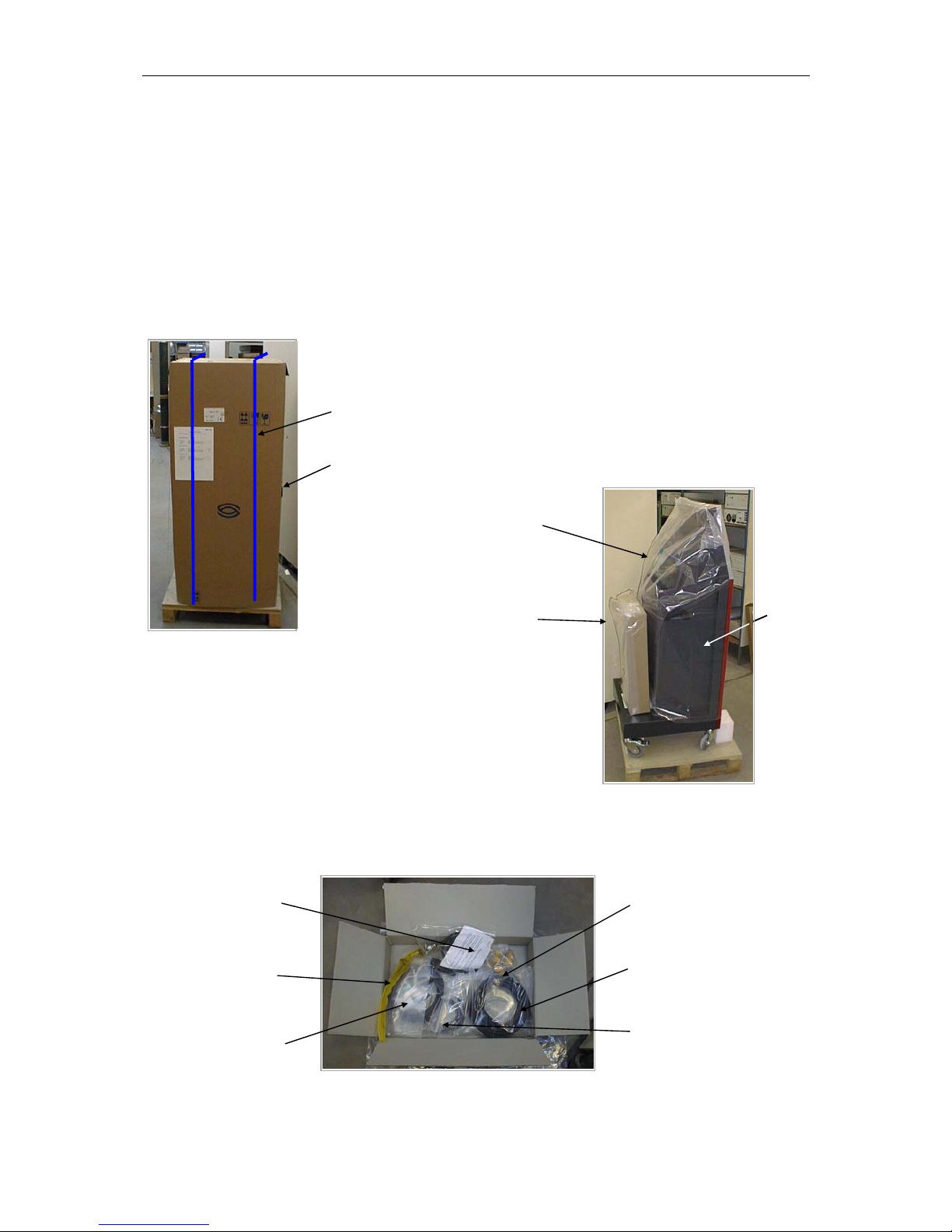
Figure 2-1 - ULTIMA 600
in its package
5. Open the accessory box on the top
(Cut the adhesive paper using a cutter).
6. Open the plastic bag containing the accessories
using a pair of scissors.
7. Check the contents of the box (Fig. 2-3).
Lock
Retainer
1. Cut the plastic retainers.
2. Unlock the lock (fig. 2-1).
3. Remove and fold the cardboard box.
4. Remove the accessory box at the rear
of the unit. (fig. 2-2)
Sampling
Sensor
Power cable
with printer
roll
Gas sampling
tube
Oil T°
sensor
Gasoline
engine speed
sensor
Spare filters
Figure 2-3 - Accessory box
Figure 2-2 - ULTIMA 600
with cardboard box
ULTIMA 600
Accessory box
Plastic
envelope

S Ref.: 21821085-0/A
Issue 02/99 2-2
Figure 2-4 - Storage compartment for
documents supplied with unit
8. Lower the unit off the pallet.
9. Stow the pallet.
10. Using a cutter, remove the plastic envelope from the unit.
11. Remove the adhesive protections from the screen and panel.
12. Open the trolley door (fig. 2-4) and check for:
- the warranty voucher,
- the user manual (Ref. 218200705),
- the metrology book.
2.1.2 - Setting up the unit
Work area:
The ULTIMA 600 must be placed:
- near a 230 volts / 50 Hertz / + ground power outlet.
- in a clean, non-corrosive atmosphere; avoid:
. body work preparation areas (sanding, paint),
. battery storage or replacement rooms,
. areas in the vicinity of gasoline flowmeters, washing gantries
. exposure to weather.
Operating temperature range:
+5 °C to +40°C.
Outside these limits, the unit is no longer under normal operating conditions.
Safety:
The power cable must be easily accessible and connected near the unit.
Note: The metrology book must always
be kept available to the government
authorities and certified inspectors. This
book contains information relative to
verification and repair of the unit.
- Garanty voucher,
- User manual
- Metrology book
s Ref.: 21821085-0/A
Issue 02/99 2-3
2.1.3 - Installing the printer paper (fig. 2-5)
• Prepare the paper roll by removing the adhesive part (cut around 10 cm off the roll).
• Pull the printer cover lock on the front panel of the unit (to do so, grasp the lower part of
the cover between your thumb and little finger and pull out, taking care to grasp the lower
part of the lock).
• Insert the paper roll in the housing so that the end moves down naturally toward the
bottom (white side downward).
• Pull out a section of paper.
• Close the flap.
• To cut the paper, pull downwards.
Figure 2-5 - Installing the printer paper
2.1.4 - Installing the tubes (fig. 2-6)
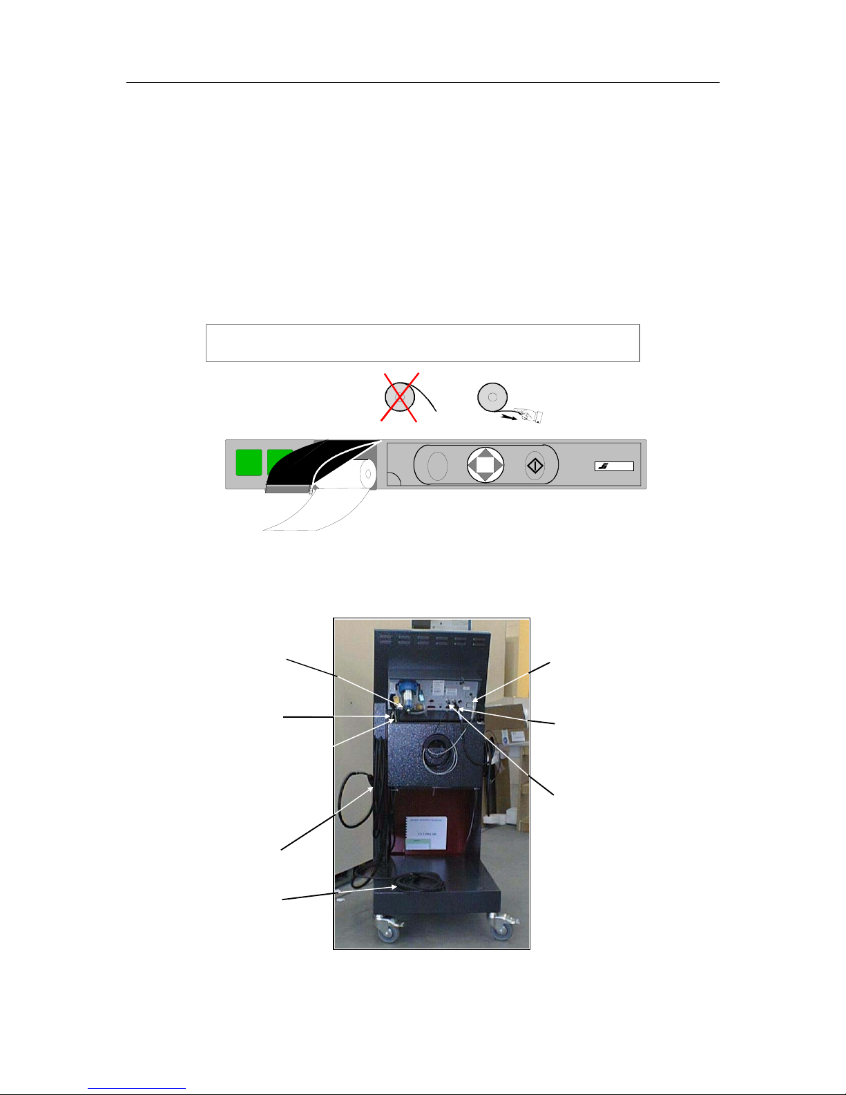
Figure 2-6 - ULTIMA 600 / REAR PANEL
Notes: Only the treated side of the paper will be printed.
Be sure the paper roll is properly positioned.
SAGEM
C
SOURIAU
Sampling sensor
stow bracket
Power cable
stow bracket
(3) - Pump water
evacuation tube
(1) - Gas
sampling tube
(4) - Gas
evacuation
tube
(6) – Temp.
sensor
(5) - Gasoline
engine speed
sensor
(2) Mains cable

S Ref.: 21821085-0/A
Issue 02/99 2-4
The tubes are connected as shown in figure 2-6. Rilsan collars are provided on the frame to
guide and keep all the tubes in place.
(1) - Exhaust gas inlet (See fig. 2-7):
• Connect the 80 cm tube to the outlet of the paper filter taking care to run it through
the Rilsan collar on the frame.
• Connect the plastic 90° elbow to the 80 cm tube and to the 7 m tube coming out of
the frame by a hole provided in the lower part.
• Engage the sampling sensor on the other end.
• Roll the gas sampling tube around the bracket provided for this purpose on the left
side of the frame.
• Stow the sampling sensor in its housing.
Figure 2-7 - Installing gas
sampling sensor
(2) - Mains power cable:
• Connect the power cable to the power filter.
• Run the cable down along the frame through the hole provided for this purpose after
equipping the cable with a plastic sheath to give it a 90° angle and hold it in this
position without damaging the cable.
• Roll the cable on the lower part of the frame.
(3) - Water evacuation tube:
• The tube is already connected to the unit.
• Run the tube down along the frame, passing it through the same Rilsan collar as the
sampling sensor tube.
• Insert it in the passage provided for this purpose in the lower part of the frame.
90° elbow
Exhaust gas
inlet tube
Sampling
sensor stow
position
Inside view of
frame
External view of
frame

s Ref.: 21821085-0/A
Issue 02/99 2-5
(4) - Gas evacuation tube:
• Engage the transparent tube on the « Gas evacuation » outlet (see fig. 2-6).
• Run tube through Rilsan collar provided for this purpose on frame.
• Cut the tube to the desired length.
(5) - Gasoline engine speed sensor:
• Connect the DIN connector to the gasoline engine speed sensor (see fig. 2-6).
• Roll cable on the small reel provided for this purpose on the right side of the frame.
(6) - Oil temperature sensor:
• Connect the oil temperature sensor to the DIN connector (see fig. 2-6 and 2.7).
• Stow it in the housing provided for this purpose in the frame.
2.1.5 - Installing the tightness fitting
The tightness fitting is secured to the power cable between the power connector and the
cable passage in the chassis.
2.1.6 - Initial startup
1. Connect the power cable to the mains outlet:
• General power supply : 195 - 253 Volts, 47 - 63 Hz, + ground.
• Current : 0.3 Amps
2. Start up the unit (On/Off switch set to position 1):
- Once started up, the SAGEM logo appears on the screen,
- After a few seconds: ULTIMA600 is displayed.
3. The standby screen is displayed
Figure 2-8 - Power up
S
GAZ
OFP
OBD
Service
ULTIMA 600

S Ref.: 21821085-0/A
Issue 02/99 2-6
4. Following power up, the ULTIMA 600 stays in « Preheating » mode for up to 15 minutes *
during which no measurement can be performed. During the last three minutes of
preheating in STANDBY mode, a time counter is displayed.
* The preheating time can vary:
15 minutes (unit cold)
1 to 7 minute(s) (unit hot)
5. For the remaining operations, refer to the user manual supplied with the unit.
Figure 2-9 - Preheating screen
Selftest
Service
GAS: PREHEATING
2’50
Selftest
←

S Ref.: 21821085-0/A
Issue 02/99 3-1
SECTION 3
DESCRIPTION / OPERATION
3.1 - GENERAL INFORMATION
The OPTIMA 600 gas analyzer is designed to simultaneously measure the carbon monoxide
(CO), the carbon dioxide (CO2), the unburned hydrocarbons (HC) and the oxygen (O2)
contained in the exhaust gases of vehicles with positive ignition engines.
The ULTIMA 600 is also designed for use with an opacimeter option.
3.2 - DESCRIPTION OF FRONT PANEL (fig. 3-1)
Figure 3-1 - ULTIMA 600 / FRONT PANEL
(1) - Graphic display (LCD type):
• Displays operator messages and the measurement results for the four gases:
- CO, CO2, O2 in volume %
- HC in volume ppm,
- the corrected CO calculated in volume %,
- the LAMBDA (λ) parameter.
(2) - Periodic inspection labels for gas analyzer and opacimeter.
(3) - Printer
1
2
34
0
STREAMIX SYSTEM INSIDE
C
SOURIAU
S Ref.: 21821085-0/A
Issue 02/99 3-2
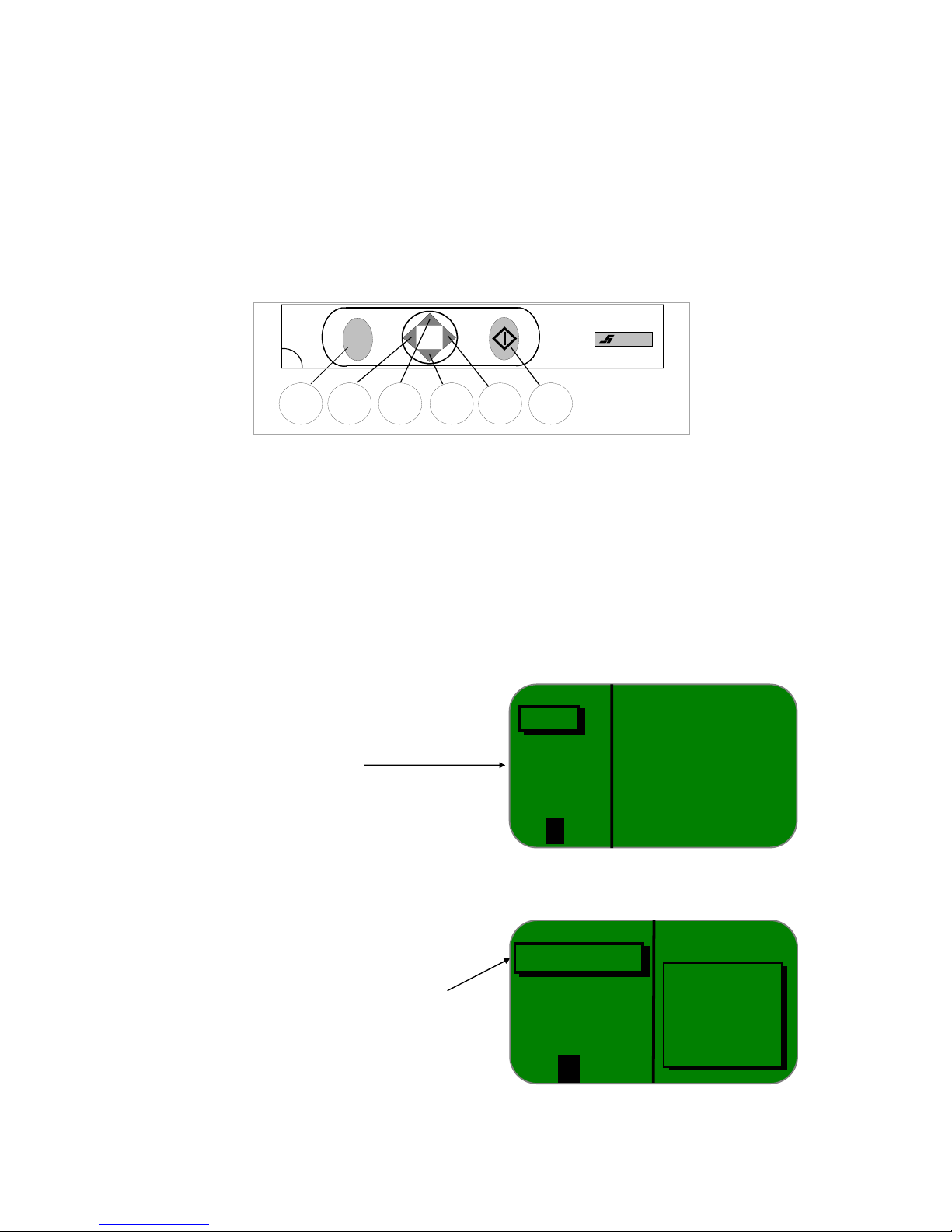
(4) - 6-key keypad, comprising:
- (5) Key C : exhaust or exit
- (6) Key < : move left
- (7) Key s : move up or increment
- (8) Key t : move down or decrement
- (9) Key > : move right
- (10) Key <> : validate or enter
Figure 3-2 - 6-key keypad
By pressing key (10), the unit goes into STANDBY mode; the SELFTEST and SERVICE
modes can then be accessed by key (8) and validated by key (10).
A series of options is proposed (tightness test, version CS FEP, Lambda control, calibration,
HC residue test, info and Å Return in the form of a scrolling menu which you can select
using keys (7) and (8).
Access and exit from a function is achieved using key (10).
To return to the standby mode, meaning exit from the SELFTEST mode, select Å .
567
8
9
10
C
SOURIAU
GAZ
OFP
OBD
Service
Å
ULTIMA 600
GAS
Standby screen
Checks that the values measured are
not diluted by air. Indicates state of
gaseous circuit from sampling sensor
up to pump (after change of filter, for
example), which is mandatory every 3
months.
SELFTEST
Tightness test
Version CS, FEP
Lambda control
Info
←
S Ref.: 21821085-0/A
Issue 02/99 3-3
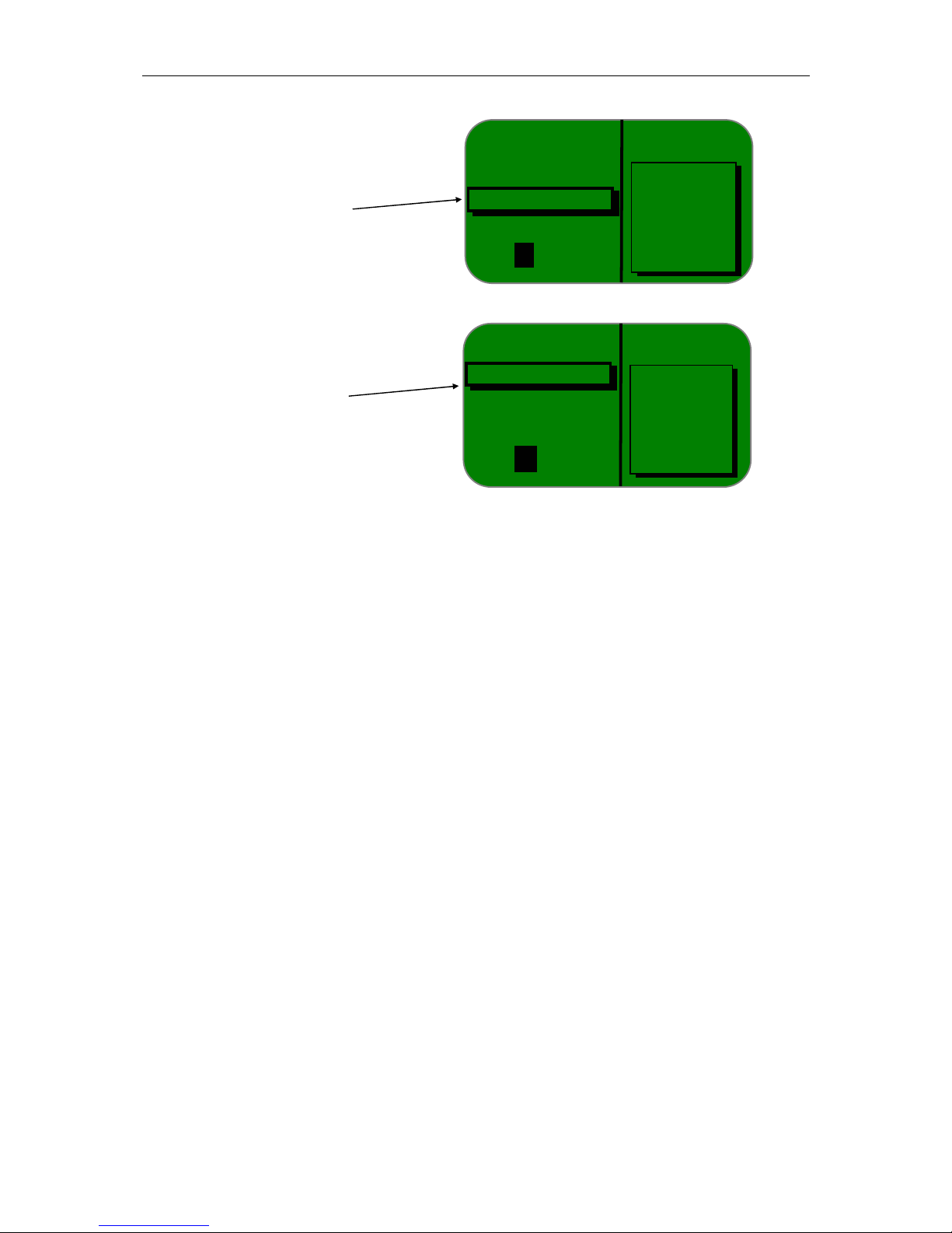
Figure 3-3 - Sequence of screens to reach selftest
A complete description of the various menus and their use is given in the Ultima 600 User
Manual. (Reference: 218200705)
SELFTEST
Tightness test
Version CS, FEP
Contrôle Lambda
Info
←
Checks exactness of
Calculation formula
among the various CO,
CO2, HC and O2
values (must be in the
immediate vicinity of 1).
Lambda control
SELFTEST
Tightness test
Version CS, FEP
Lambda control
Info
←
Software version,
Checksum
Cell coefficient
V
ersion CS, FEP

S Ref.: 21821085-0/A
Issue 02/99 3-4
3.3 - DESCRIPTION OF REAR PANEL (fig. 3-4)
Figure 3-4 - ULTIMA 600 / REAR PANEL
1. On/Off switch with mains power input socket and fuse holder cover
2. Paper filter for pump protection.
3. Exhaust gas inlet for 4-cycle vehicles located in upper part of main filter (2).
4. Pump water evacuation outlet
5. Reference gas inlet
6. Connector, BB9 type, RS232 serial link
7. Connector, DB25 type, printer parallel link.

S Ref.: 21821085-0/A
Issue 02/99 3-5
8. Connector, mini DIN type, keyboard link.
9. Connector, DIN type, temperature sensor link.
10. Connector, DB9 type, OBD vehicle link
11. Connector, DIN type, speed sensing clamp link for first cylinder of gasoline vehicles.
12. Connector, DB15 type, opacimeter cell link
13. Connector, DIN type, piezo speed sensing clamp link for Diesel vehicles.
14. Mains female connector to be used only for power supply of opacimeter cell
4030-0920.
15. Gas outlet.
16. Gas outlet if Nox option is used.
17. Cell end-of-protection filter.
18. First paper filter in particle filtering line, placed vertically.
19. High capacity bowl containing vyon filter cartridge.
20. Machine characteristics label.
21. O
2
cell seal label
.
22. Machine nameplate.
23. Punching plate.
24.Machine sealing device.
25.Air and heat evacuation vents.
26.EC marking label.
S Ref.: 21821085-0/A
Issue 02/99 3-6
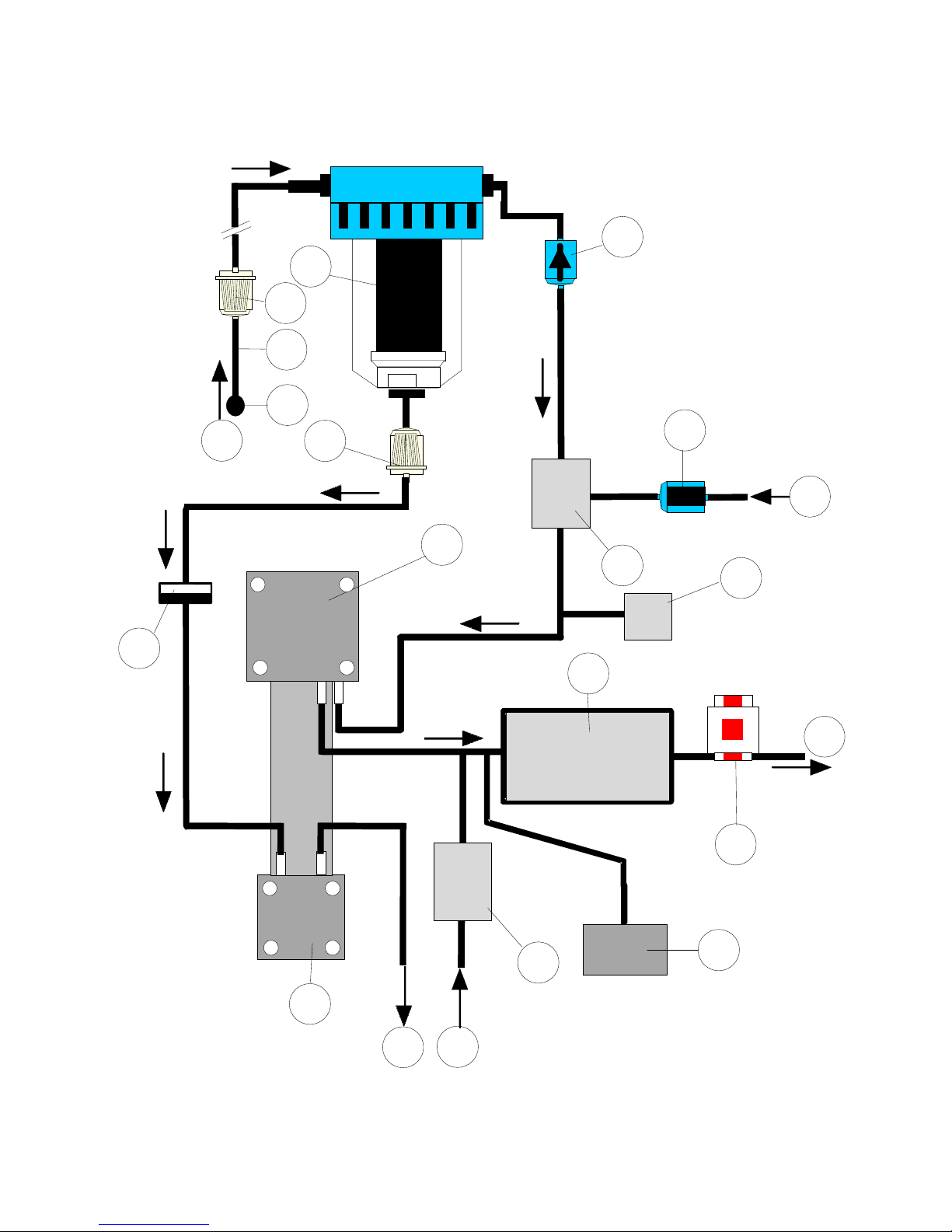
3.4 - DESCRIPTION OF PNEUMATIC CIRCUIT
Gas circ.drw
B
4
3
10
7
9
5
6
15
1
2
16
8
13
12
11
A
C
D
E
14
Figure 3.5 - Pneumatic circuit

S Ref.: 21821085-0/A
Issue 02/99 3-7
1. Gas sampling sensor: comprises an adjustable stainless steel flexible end fitting with
attachment spring.
2. Hose: 7-meters long, connects sampling sensor to analyzer gas inlet on rear panel.
3. -Line paper filter: first filter, located in gas sampling circuit, placed vertically at the rear of
the analyzer. This filter is not regenerative.
4. Main filter: Vyon filter, retaining particles greater than 25 microns. This filter is used in
coalescer mode (gas circulating inside filter toward outside) to trap micro droplets of water
through the filter and large solid impurities. The water drops coming out of the filter drop to
the bottom of the bowl where they are sucked in by a pump head. The cartridge is
washable.
5. Cell protection filter for measurement mode: fine filter used to protect the cell from the
smallest particles during the « measurement » phase.
6. Gas flow monitor: displays « gas flow fault » alert message when clogging in
corresponding filters occurs.
7. Cell protection filter for calibration mode implementing activated charcoal: Filter used to
protect the cell from hydrocarbons and external environment humidity during the
« calibration » phases.
8. Solenoid valve: enables passage of air during calibration sequences to allow leaving the
sensor in the exhaust pipe.
9. Analysis cell: Instrument based on infrared analysis principle.
10.Oxygen sensor: Placed at outlet of pneumatic circuit to avoid modifying sampling of gas to
be measured.
11.Pressure sensor: Integrated in gas analysis cell for correction of pressure of
concentrations of gases measured.
12.Quick coupler: Enables supply of a reference gas to cell (pump stopped).
13.Water head pump: Pump used to evacuate water condensation to the outside.
14.Gas head pump: Pump used to circulate gases through the cell.
15.Check valve: used to avoid pump backflows.
16.Pump safety filter: Filter used to protect the pump. This filter is not regenerative.
A : Sampling sensor inlet
B : Calibration inlet (non-polluted air)
C : Gas outlet
D : Adjustment inlet
E : Water outlet

S Ref.: 21821085-0/A
Issue 02/99 3-8

S Ref.: 21821085-0/A
Issue 05/99 4-1
SECTION 4
PREVENTIVE MAINTENANCE
4.1 – "GAS" mode customer selftest
Selftests accessible by customer:
• Tightness test
• Version, CS, FEP
• Lambda control
• Calibration
• HC residue test
• Info adjustment
• IR cell status
4.1.1 – Tightness test
Purpose:
To check tightness of gas circuit from sampling sensor up to pump.
Frequency:
This test should be performed:
- each time the analyzer requests the operator to perform the test
- each time a filter is replaced.
Procedure:
Select « tightness test » in the Selftest menu using the t and s keys.
• Place the end of the sensor in the sleeve provided for this purpose,
• Press the "Validation" key; the vacuum pressure information is indicated on the
display. A 30 s downcount starts when the pump stops. At the end of the
downcount, the analyzer gives the test result.
 Loading...