

Page 1
SAGEM-LINK F
Microwave Radio Links
7 GHz – 38 GHz
Installation and Operation Manual
288 055 571-04
Issue 04 : July 2005
Page 2

SAGEM-LINK F 288055571-04
Installation and Operation Manual
Page 2/142
Issue 04 : July 2005
Reproduction and communication prohibited without the written permission of Sagem Communication
No reproduction without the written consent of Sagem Communication.
Sagem Communication reserves the right to change the specifications for improvement.
All trademarks are registrated by their owners.
Page 3

SAGEM-LINK F 288055571-04
Installation and Operation Manual
Page 3/142
Issue 04 : July 2005
Reproduction and communication prohibited without the written permission of Sagem Communication
HANDBOOK CHANGE LIST
(Each new edition supersedes the previous edition)
No. Issue
(No., date)
Change
Description
Changed
Pages
(Volume 1)
01 July 2004 Creation of document
02 September 2004 All pages
03 November 2004 All pages
04 July 2005 All pages
Page 4

SAGEM-LINK F 288055571-04
Installation and Operation Manual
Page 4/142
Issue 04 : July 2005
Reproduction and communication prohibited without the written permission of Sagem Communication
SAGEM-LINK F
INSTALLATION AND OPERATION MANUAL
Table of Contents
CHAPTER 1 - INSTALLATION ............................................................................................. 7
1.1 - Overview................................................................................................................... 7
1.2 - Unpacking the Equipment ........................................................................................ 7
1.3 - IDU Installation ......................................................................................................... 8
1.4 - Antenna Installation .................................................................................................. 8
1.4.1- Antenna Mount ................................................................................................... 9
1.4.2 - Typical Antenna Installation ............................................................................ 10
1.5 - Installing the ODU(s) .............................................................................................. 10
1.6 - Installing the IDU to ODU Coaxial Cable(s) ........................................................... 16
1.7 - Powering Up the System ........................................................................................18
1.8 - Aligning the Antennas............................................................................................. 20
1.9 - Connecting IDU to External Equipments ................................................................ 23
1.9.1 - IDU Front Panel Access Description ............................................................... 23
1.9.2 - IDU Rear Panel Access Description ............................................................... 24
1.9.3 - Connectors Pinout Description........................................................................ 24
CHAPTER 2 - COMMISSIONING ....................................................................................... 36
2.1 - Overview................................................................................................................. 36
2.2 - Preliminary Verifications ......................................................................................... 36
2.3 - Frequency Scan...................................................................................................... 37
2.4 - Receive Signal Level .............................................................................................. 37
2.5 - Tributary Tests........................................................................................................ 38
2.6 - Engineering Order Wire Test (optional).................................................................. 39
2.7 - Alarm Relays and I/O Dry Loops Test (optional).................................................... 39
2.7.1 - Simulating an IDU Alarm ................................................................................. 39
2.7.2 - Simulating an ODU Alarm ............................................................................... 39
2.7.3 - Simulating a Tributary Alarm ........................................................................... 39
2.7.4 - Simulating a RSL Alarm .................................................................................. 39
2.7.5 - Simulating a Custom Alarm............................................................................. 40
2.7.6 - Testing Input Dry Loops .................................................................................. 40
2.7.7 - Testing Alarm Relays ...................................................................................... 40
2.8 - 1+1 Verification (optional)....................................................................................... 41
2.9 - BER Measurement ................................................................................................. 43
2.10 - Recording Configuration Information.................................................................... 44
CHAPTER 3 - SAGEM-LINK F PILOT DESCRIPTION ...................................................... 48
3.1 - Overview................................................................................................................. 48
3.2 - SAGEM LINK F Pilot : Main Operations to Configure a Link ................................. 49
3.2.1 - Installing the SAGEM – LINK F Pilot Software................................................ 49
3.2.2 - Connecting the Laptop to SAGEM – LINK F IDU............................................ 49
3.2.3 - Link Preliminary Configuration ........................................................................ 50
3.2.4 - Completing Link Configuration ........................................................................ 55
3.3 - SAGEM-LINK F Pilot : Menus Description ............................................................. 64
3.3.1 - Configuration Menu .........................................................................................64
3.3.2 - Alarms Menu ................................................................................................... 66
3.3.3 - Monitoring Menu.............................................................................................. 71
3.3.4 - Parameters Menu ............................................................................................ 77
3.3.5 - Downloads Menu............................................................................................. 81
3.3.6 - NMI Menu ........................................................................................................ 82
3.3.7 - Tools Menu...................................................................................................... 88
3.3.8 – Changing an IDU Configuration...................................................................... 95
Page 5

SAGEM-LINK F 288055571-04
Installation and Operation Manual
Page 5/142
Issue 04 : July 2005
Reproduction and communication prohibited without the written permission of Sagem Communication
CHAPTER 4 - TROUBLESHOOTING................................................................................. 97
4.1 - Overview................................................................................................................. 97
4.2 – Visual Inspection.................................................................................................... 97
4.3 – Troubleshooting Steps........................................................................................... 98
4.3.1 – Define the symptom........................................................................................ 98
4.3.2 – Isolate the problem .........................................................................................98
4.3.3 – Fix the problem ............................................................................................... 98
4.4 – Alarms and Status Indication LED ......................................................................... 98
4.5 - SAGEM-LINK F Pilot Alarm Menus ........................................................................ 99
4.5.1 – Alarms Screen ................................................................................................ 99
4.5.2 – Direct and Indirect Alarms ............................................................................ 101
4.5.3 – Equipment Log ............................................................................................. 101
4.6 – Typical SAGEM-LINK F Pilot Screens................................................................. 102
4.6.1 – No connection to the IDU from the Pilot software ........................................ 102
4.6.2 – No Local equipment...................................................................................... 102
4.6.3 – No Remote Radio .........................................................................................103
4.6.4 – RSL Alarms .................................................................................................. 103
4.6.5 – Transmit Power alarm .................................................................................. 103
4.6.6 – Minor alarms ................................................................................................. 104
4.6.7 – No alarm .......................................................................................................104
4.7 – Replacing an ODU ............................................................................................... 105
4.8 – Replacing a Cable Interface module.................................................................... 105
4.9 – Replacing an IDU................................................................................................. 105
CHAPTER 5 - SYSTEM DESCRIPTION........................................................................... 106
5.1 - Overview............................................................................................................... 106
5.2 – System Composition............................................................................................ 106
5.2.1 - IDU Versions ................................................................................................. 108
5.2.2 – Cable Interface Module Versions ................................................................. 108
5.2.3 – ODU Versions............................................................................................... 108
5.3 – SAGEM-LINK F Block Diagram ........................................................................... 110
5.4 – IDU Description.................................................................................................... 111
5.5 – Cable Interface Module Description..................................................................... 112
5.6 – Outdoor Unit Description ..................................................................................... 112
5.7 – Protected Configurations ..................................................................................... 113
5.7.1 – 1+1 Mute Hot Standby (MHSB).................................................................... 113
5.7.2 – 1+1 Space Diversity...................................................................................... 113
5.7.3 – 1+1 Frequency Diversity............................................................................... 114
CHAPTER 6 - ETHERNET OPTION ................................................................................. 115
6.1 - Overview............................................................................................................... 115
6.2 - Ethernet and E1 Combinations Description ......................................................... 115
6.3 - Ethernet Features Description.............................................................................. 119
6.3.1 - Ethernet Bridging........................................................................................... 119
6.3.2 – Bandwidth Allocation .................................................................................... 120
6.3.3 – Ethernet Interface Configurations................................................................. 121
6.4 - Ethernet Configuration.......................................................................................... 122
6.5 - Ethernet Alarms .................................................................................................... 122
6.5.1 - Ethernet RJ45 LEDs...................................................................................... 122
6.5.2 – Sagem Link F Pilot Ethernet Alarm .............................................................. 123
6.6 - Ethernet Troubleshooting ..................................................................................... 124
APPENDIX 1 - SAGEM-LINK F SPECIFICATIONS ......................................................... 125
General .........................................................................................................................125
Transmitter.................................................................................................................... 126
Receiver........................................................................................................................ 127
Tributaries ..................................................................................................................... 128
Auxiliary Channels and Management Interfaces .......................................................... 128
Mechanical.................................................................................................................... 128
Consumption................................................................................................................. 129
Page 6

SAGEM-LINK F 288055571-04
Installation and Operation Manual
Page 6/142
Issue 04 : July 2005
Reproduction and communication prohibited without the written permission of Sagem Communication
Environmental ............................................................................................................... 129
APPENDIX 2 - SAGEM-LINK F PART NUMBERS .......................................................... 130
Link Composition .......................................................................................................... 130
SAGEM LINK F Modules Part Numbers....................................................................... 131
SAGEM LINK F ODU Part Numbers ............................................................................ 132
APPENDIX 3 - MISCELLANEOUS ................................................................................... 136
Changing 8 GHz ODU T/R Spacing Procedure........................................................... 136
Using Pilot software with an Ethernet Connection........................................................ 138
Upgrading a 2x2/4x2 Mbit/s IDU................................................................................... 139
Page 7

SAGEM-LINK F 288055571-04
Installation and Operation Manual
Page 7/142
Issue 04 : July 2005
Reproduction and communication prohibited without the written permission of Sagem Communication
Chapter 1
Installation
1.1 - Overview
This chapter explains how to install and set up SAGEM LINK F radio links. The main topics covered are :
• Unpacking the Equipment
• IDU installation
• Antenna installation
• ODU installation
• IDU to ODU Coaxial cable installation
• Powering up the system
• Antenna alignment
• Connecting IDU to external equipments
1.2 - Unpacking the Equipment
Verify that the items received are compliant with the packing list.
If any part of the equipment is damaged, contact Sagem representative for repair or replacement
instructions.
The IDU and ODU are packaged in two separate boxes. In addition, the optional items are
packaged in a separate container.
The IDU box contains, the IDU with cable interface module (one for 1+0 systems, two for 1+1
systems), the DC Power supply cable and a CDROM including the user manual and the SAGEM
LINK F Pilot software.
The ODU box contains only one ODU.
Save case and shipping material, in case the equipment has to be returned.
Page 8
SAGEM-LINK F 288055571-04
Installation and Operation Manual
Page 8/142
Issue 04 : July 2005
Reproduction and communication prohibited without the written permission of Sagem Communication
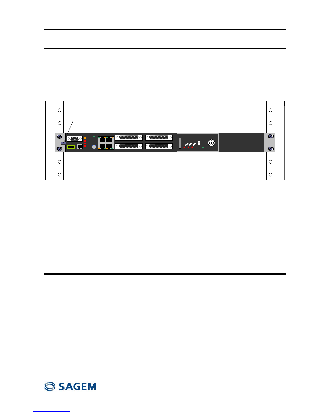
1.3 - IDU Installation
To install the IDU in a 19-inch rack :
• Attach the IDU in the 19-inch rack using four 6x12 stainless steel hex screws and washers into the
corresponding rack cage nuts. This attachment grounds the IDU to the earth.
Maint
Mux
Tribs
Cust
S
On
Off
Call
PC
POWER
EOW
Mgr 100bT
EastWest
TRIB 1- 4 TRIB 5- 8
TRIB 9-12 TRIB 13-16
ODU
POWER
Faston Male Plug
Figure 1.1 - IDU installation
• An additional grounding is possible by the use of a Faston plug (left side of the IDU). Use a 6
mm2 section cable (minimum length required).
NOTE: When more than one IDU are to be mounted in the rack, it is recommended to keep a gap of 1
unit between two IDUs.
1.4 - Antenna Installation
Three types of antenna with several diameters are available for SAGEM LINK F radios.
• Integrated antenna with Sagem Link F ODU interface (0.3m, 0.6m, 0.9m, 1.2m or 1.8m
diameter). With these antennas, the ODU is directly attached on the antenna. In some protected
configuration using a coupler, the coupler is attached to the antenna, and the ODU are attached
on the coupler.
• External antenna with standard rectangular waveguide flange, which is connected to the
SAGEM LINK F ODU with a flex guide.
• External antenna with two access (dual polarized antenna) connected by two flex guides to the
ODUs.
Antennas models depend on the frequency bands :
• 7 GHz → 7.1 - 7.7 GHz
• 8 GHz → 8.025 - 8.5 GHz
• 13 GHz → 12.75 - 13.25 GHz
Page 9

SAGEM-LINK F 288055571-04
Installation and Operation Manual
Page 9/142
Issue 04 : July 2005
Reproduction and communication prohibited without the written permission of Sagem Communication
• 15 GHz → 14.4 - 15.35 GHz
• 18 GHz → 17.7 - 19.7 GHz
• 23 GHz → 21.2 - 23.6 GHz
• 26 GHz → 24.5 - 26.5 GHz
• 38 GHz → 37 - 39.5 GHz
Alternative antennas to those specified by Sagem may be used, but they must meet the following
requirements
• Minimum gain to achieve adequate link margin,
• Radiation Pattern Envelope compliant to the network and country regulations
• Mechanical characteristics to meet specific site requirements (wind and frost resistance)
NOTE: With some antennas, the manufacturer’s guarantee applies only if the antenna feed is
pressurized. Therefore, it is essential to observe the recommendations relative to the selected
antenna type. Provision must therefore be made for:
y
installation and connection of a pressurizing system if the antenna is connected to the ODU
with a waveguide;
y
use pressurization windows and seals to protect waveguide connections.
1.4.1- Antenna Mount
In most cases, the antenna mounts provided by antenna manufacturers fit on tubular poles
(diameter 88.9 to 114 mm).
If the antenna is installed on towers using another type of structure (e.g., square-section tower),
special mounting kits must be used for this support.
The following precautions must always be taken :
- Allow enough clearance (± 10°) about the alignment axis. Leave also adequate space
around the ODU to allow easy mounting.
- make sure that nothing may obstruct the link, even partially, especially in the near field of
view,
- keep enough room for access to the antenna and ODU (for set-up and maintenance
measurements),
- install proper lightning rod and earthing,
Note: If there is an existing lightning rod, make sure that the ODU installation site is covered by
the lightning protection cone.
- misalignment under extreme weather conditions must not exceed ± 20 min angle in elevation
and azimuth.
The antenna mount may be secured in different ways depending on the antenna installation site
type and environment :
- mounting pole secured to the HEA section with a back-plate or clips,
- mounting pole secured to a square-shaped base plate with threaded rods. The base plate is
set on top of a resilient plate which may be installed on the terrace of a building without
affecting water-tightness,
- wall-mounted staff on the building front,
Page 10

SAGEM-LINK F 288055571-04
Installation and Operation Manual
Page 10/142
Issue 04 : July 2005
Reproduction and communication prohibited without the written permission of Sagem Communication
- antenna mount secured directly to a tower tube (diameter 88.9 or 114 mm),
- antenna support secured to a square-section tower tube with adapters.
1.4.2 - Typical Antenna Installation
Refer to the antenna manufacturer procedures.
1.5 - Installing the ODU(s)
Depending on the configuration, and on the antenna type, there are several ODU mounting
possibilities :
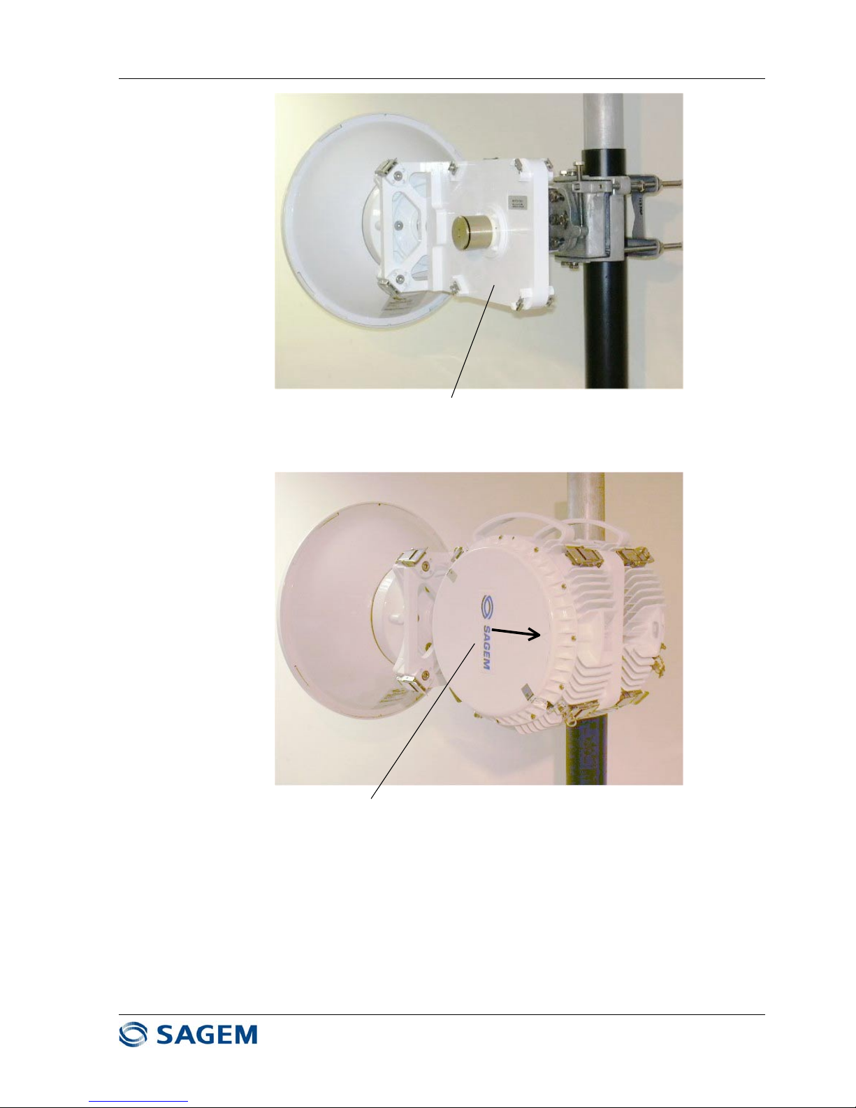
• 1+0 Configuration with integrated antenna : (or 1+1 configuration with two antennas)
The ODU is directly attached on an integrated antenna with four latches. It is connected to the
IDU by a single coaxial cable terminated with N male connectors.
Figure 1.2 - SAGEM LINK F ODU with an Integrated Antenna
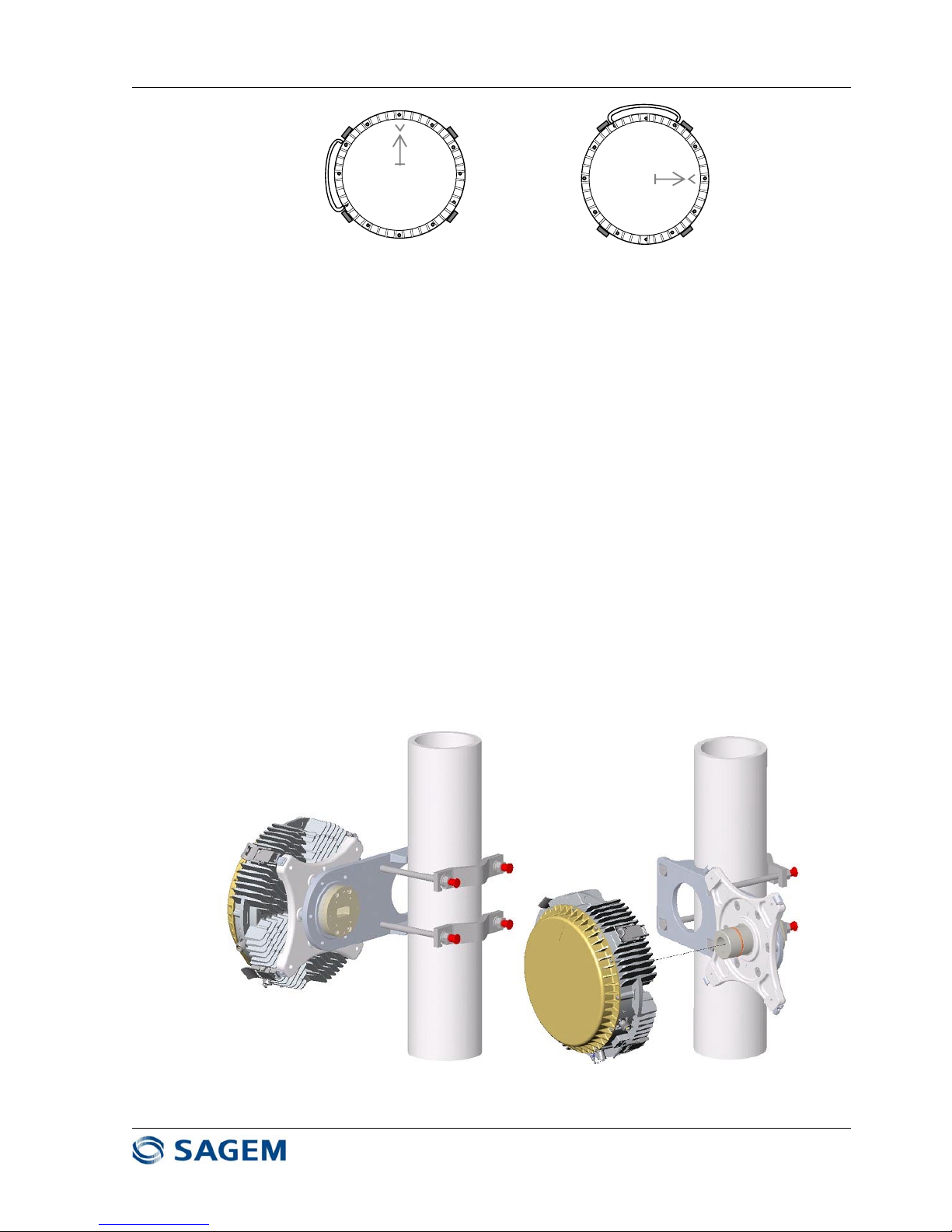
Setting the Polarization :
If antenna has a circular waveguide interface (7 GHz, 8 GHz or 38 GHz), polarization depends
only on the ODU position. For vertical polarization, make sure that the arrow on the ODU cover is
vertical, for horizontal polarization, turn the ODU from 90 degrees.
Page 11
SAGEM-LINK F 288055571-04
Installation and Operation Manual
Page 11/142
Issue 04 : July 2005
Reproduction and communication prohibited without the written permission of Sagem Communication
Horizontal PolarizationVertical Polarization
Figure 1.3 – Polarization Setting for the ODU
If antenna has a rectangular waveguide interface (13 GHz, 15 GHz, 18 GHz, 23 GHz and 26
GHz), then polarization depends on the antenna source position.
Note that ODU waveguide output must always be in the same position compared to antenna
waveguide input.
For vertical polarization, turn antenna source in order to have the large side of the waveguide in
horizontal position according to antenna manufacturer procedure. Install the ODU accordingly
For horizontal polarization turn antenna source to have the large side of the waveguide in vertical
position. Turn also the ODU in order to have coincidence between ODU and antenna
waveguides.
• 1+0 Configuration with remote mount and standard antenna :
In case of the use of a standard antenna (i.e. large antenna without SAGEM LINK F ODU
interface), the ODU is mounted on a pole with a remote mount and connected to the antenna with
a standard rectangular flex guide.
Polarization depends on the antenna source position (vertical polarization is obtained when the
big side of the antenna waveguide flange is horizontal).
Figure 1.4 - SAGEM LINK F ODU Remote mount
Page 12

SAGEM-LINK F 288055571-04
Installation and Operation Manual
Page 12/142
Issue 04 : July 2005
Reproduction and communication prohibited without the written permission of Sagem Communication
• 1+1 Configuration with a Coupler and an Integrated Antenna :
The coupler is attached on the integrated antenna with four bolts. Two ODUs are mounted
vertically on the coupler with four latches. Each ODU is connected to its modem by a coaxial
cable.
As in most cases the coupler is not symmetrical, it is important to identify which ODU is
connected to the main position, and which ODU is connected to protection (standby) position.
The main and standby ODU positions are indicated on the coupler.
Whatever the polarization is, 1+1 the coupler is always mounted in the same position. There are
two types of coupler :
- Andrew coupler : for this type of coupler the arrow on the ODU cover must be vertical
- Filtel coupler : for this type of coupler, the arrow on the ODU cover must be horizontal.
Page 13

SAGEM-LINK F 288055571-04
Installation and Operation Manual
Page 13/142
Issue 04 : July 2005
Reproduction and communication prohibited without the written permission of Sagem Communication
A
ndrew Coupler
ODU arrow is in vertical
position (Andrew coupler)
Standb
y
ODU
Main ODU
Figure 1.5a - SAGEM LINK F 1+1 Configuration with integrated antenna and Andrew
coupler
Page 14
SAGEM-LINK F 288055571-04
Installation and Operation Manual
Page 14/142
Issue 04 : July 2005
Reproduction and communication prohibited without the written permission of Sagem Communication
Filtel Coupler
ODU with Filtel coupler
Horizontal arrow
Figure 1.5b – SAGEM LINK F 1+1 Configuration with integrated antenna and Filtel coupler
On the coupler there is a label or a marking indicating the position of main and stand by ODUs.
Page 15

SAGEM-LINK F 288055571-04
Installation and Operation Manual
Page 15/142
Issue 04 : July 2005
Reproduction and communication prohibited without the written permission of Sagem Communication
Polarization setting :
- Coupler : ODUs are mounted vertically on the coupler. Depending on the coupler type the
arrow on the ODU cover must be horizontal (Filtel) or vertical (Andrew).
- The polarization can be adjusted from turning the coupler polarizer from 90 degrees
(Andrew) or by replacing polarizer (Filtel). Refer to coupler supplier instructions.
- Antenna : If the antenna has a rectangular waveguide interface, rotate antenna source to
have the wanted polarization. Make sure that polarizations are the same for the antenna
and for the coupler.
Vertical Polarization Horizontal Polarization
Figure 1.6 – Setting the Polarization for Andrew Coupler
Vertical Polarization Horizontal Polarization
Figure 1.7 – Setting the Polarization for Filtel Coupler
• 1+1 Configuration with a Coupler Remote Mounted and a Standard Antenna :
The coupler is attached on the remote mount and connected to the standard antenna by a flex
guide.
The two ODUs are vertically mounted on the coupler, with the arrows in vertical (Andrew) or
horizontal position (Filtel). Each ODU is connected to the IDU with a coaxial cable.
Page 16

SAGEM-LINK F 288055571-04
Installation and Operation Manual
Page 16/142
Issue 04 : July 2005
Reproduction and communication prohibited without the written permission of Sagem Communication
Polarization setting is done by turning antenna source.
As coupler is not symmetrical in most cases, it is important to identify main position (lowest
insertion loss) and standby position.
It is also necessary to identify ODU cables (main or standby) with a label.
• 1+1 Frequency Diversity Configuration with Remote Mounts and a Dual Polarized Antenna :
In this configuration each ODU is remote mounted on a pole, and is connected to an antenna
access with a flex guide.
It is important to identify ODU cables for the one which is on vertical polarization (main), and the
one which is horizontal polarization (standby).
1.6 - Installing the IDU to ODU Coaxial Cable(s)
Recommended cables coaxial cables are Belden 9914 and Andrew LDF4-50A. If an other type of
cable is used, make sure it is compatible with outdoor use. This cable should be double or triple
shielded. Cable impedance is 50 Ohm, and is terminated by two N male connectors.
N connectors must be compatible with the cable, and connector mounting procedure must follow
connector manufacturer recommendations.
Install one cable in a 1+0 system or two cables in a 1+1 system.
It is very important to protect N connectors against water : wrap Isolation tape (15 cm) over the
coax cover. Start winding from coax cover with one half overlap with each winding in order to
protect completely connection from rain action. Press with fingers the tape and make sure the
protection is correct.
NOTE: Cables must be installed in compliance with national and local regulations and meet the
specific requirements of the installation site.
Some precautions are necessary when installing the equipment on unprotected places (e.g.,
antenna towers, building terraces, etc.) to prevent equipment from damage by lightning.
In a 1+1 system when two cables are installed, it is very important to identify main cable and
standby cable. If the cables are not labeled, it is necessary to perform a resistance check to
identify each cable.
Disconnect N connectors from IDU, and short circuit one of the N connector on the ODU side
(while the other one is open), and measure cable resistance on the IDU side. The lowest
resistance corresponds to the short circuited cable.
Put labels on both sides of the cables.
Remove the short circuit, make sure connectors are clean and dry, and connect proper cable to
each ODU.
Cable Grounding
It is necessary to ground properly ODU to IDU cable for a good lightning protection. For this
purpose, a cable grounding kit is provided as an option.
Page 17

SAGEM-LINK F 288055571-04
Installation and Operation Manual
Page 17/142
Issue 04 : July 2005
Reproduction and communication prohibited without the written permission of Sagem Communication
Figure 1.9 : SAGEM-LINK F Grounding Kit
The number of necessary grounding points depends on the site, and on the cable length.
Normally, a good protection is achieved with :
• A grounding kit on the cable close to the ODU
• A grounding kit on the cable at the building entrance
• A grounding kit on the cable at the bottom of the pylon
• A grounding kit each 50 meters for long cables.
Page 18
SAGEM-LINK F 288055571-04
Installation and Operation Manual
Page 18/142
Issue 04 : July 2005
Reproduction and communication prohibited without the written permission of Sagem Communication
1.7 - Powering Up the System
Before powering up the Sagem Link F terminal, check that :
IDU and ODU and cables are properly grounded
IDU and ODU are connected together with right coaxial cable(s). in 1+1 operation, main and
standby cables have been previously identified and connected to the main and standby IDU
cable interfaces
To Main
ODU
DC Power In
To Standby
ODU
Main Channel
On/Off Switch
Standby Channel
On/Off Switch
Green LED
"Power"
Maint
Mux
Tribs
Cust
Call
S
On
Off
POWER
S
On
Off
POWER
Main Cable Interface Standby Cable Int erface
Figure 1.10 – SAGEM LINK F 1+1 IDU
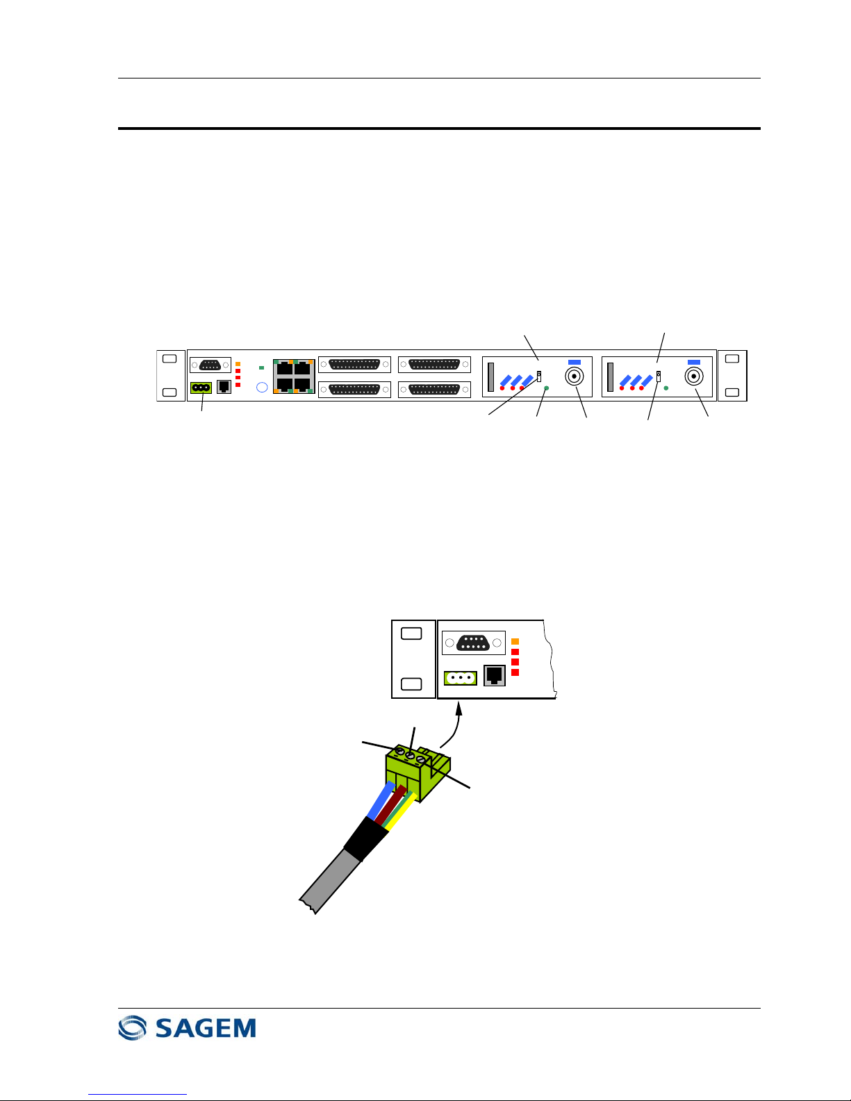
Input DC Power Voltage is within specified range : - 36 VDC to –59 VDC (-48 VDC nominal).
Measure DC voltage (polarity and amplitude) on the cable plug before connection into the
IDU. Negative voltage must be used only. DC Connector Pinout is given in Figure 1.11.
Maint
mux
Tribs
Cust
-48VDC
GROUND
(0 VDC)
GROUND
Figure 1.11 : IDU DC Input Connector
Page 19

SAGEM-LINK F 288055571-04
Installation and Operation Manual
Page 19/142
Issue 04 : July 2005
Reproduction and communication prohibited without the written permission of Sagem Communication
Plug DC connector into IDU connector. If the terminal is a 1+0 system, switch on the terminal
with the switch in front panel. If the terminal is a 1+1 system, switch on both switches.
The green LED(s) labeled "Power" should be lit.
Connect a PC on IDU front panel DB9 connector Labeled "PC" and run the Sagem Link F Pilot
software
Verify and change if necessary, terminal local parameters (refer to Sagem Link Pilot
description in chapter 4) :
- Transmit frequency,
- capacity,
- modulation,
- transmit power
- Link ID Code
- ATPC must be in the "Off" position at that time
Unless the link is already operating (remote parameters are displayed on the right side of the
main screen of the Pilot software), make sure local terminal parameters are in accordance
with far end terminal parameters. (Frequency, capacity, modulation, and Link ID Code must
match)
If remote terminal parameters are good and if the main screen displays a "No Remote Radio"
message, it means antennas are not properly aligned.
Page 20
SAGEM-LINK F 288055571-04
Installation and Operation Manual
Page 20/142
Issue 04 : July 2005
Reproduction and communication prohibited without the written permission of Sagem Communication
1.8 - Aligning the Antennas
Antenna alignment is performed with both terminals operating, in normal weather conditions. The
receive signal level (RSL) voltage is available on the ODU BNC connector.
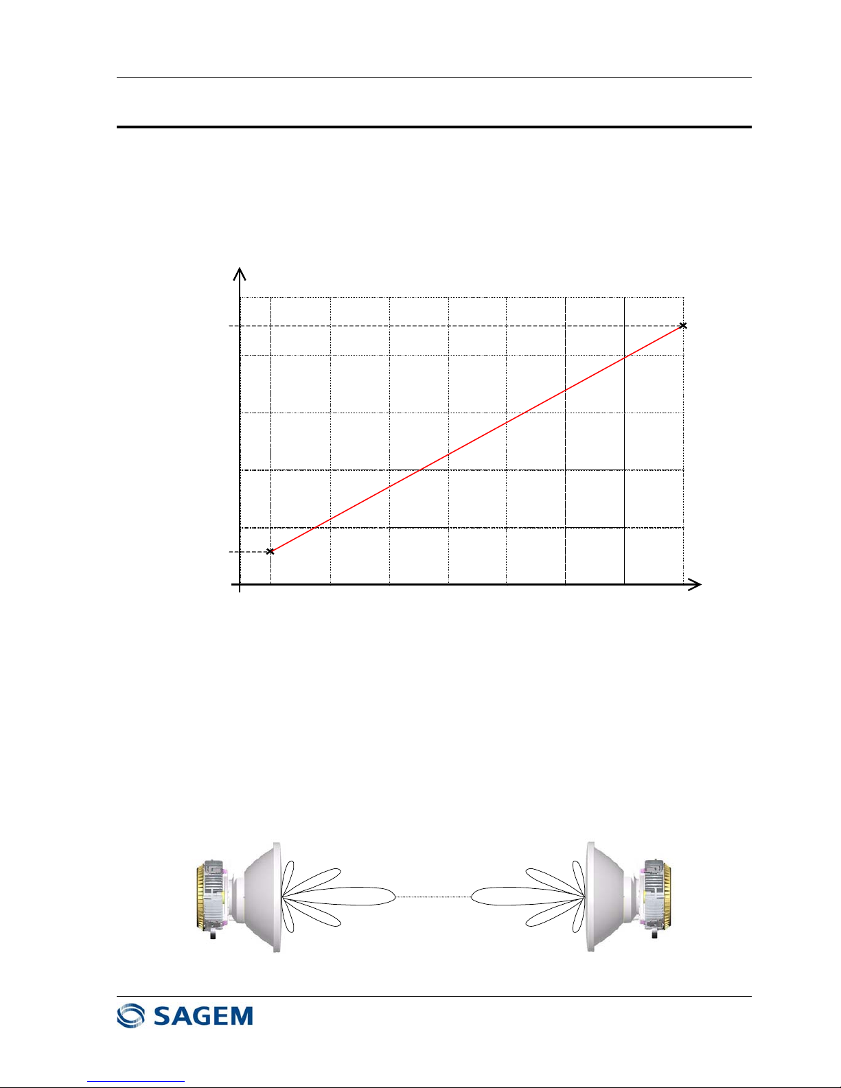
A typical RSL curve at ODU access is given on Figure 1.12 The highest the RSL voltage is, the
highest is the receive signal level.
-90 dBm
1 V
2 V
3 V
4 V
5 V
RSL Voltage
RSL at ODU Input
-80 dBm -70 dBm
-60 dBm
-50 dBm -40 dBm -30 dBm -20 dBm
0.5 V
4.5 V
Figure 1.12 : Typical SAGEM LINK F Receive Signal Level Voltage
Note : RSL is measured at ODU antenna port. In some 1+1 systems involving a coupler or a
remote mount antenna, it is necessary to take in account branching losses to know the actual
power at antenna access.
Optimal performance is done when main antenna lobe is aligned with the center of the remote
end antenna.
It is important to identify main lobe antenna, by rotating the antenna to have the maximum RSL
voltage. Note there is around 25 dB difference between side lobes and main lobes (1.5 V).
Good Alignment
Page 21

SAGEM-LINK F 288055571-04
Installation and Operation Manual
Page 21/142
Issue 04 : July 2005
Reproduction and communication prohibited without the written permission of Sagem Communication
Bad Alignment
Figure 1.13 : Antenna Alignment
The expected receive signal level has previously being determined and depends on frequency,
remote transmit power, local and remote antenna gains, and length hop.
Use the following procedure successively on both ends of the link to align the antenna :
1- Make sure remote transmit power is set in order to avoid overload at receive input (i.e. RSL
less than –20 dBm).
2- Verify that remote terminal is operational
3- Remove the cap on the local ODU BNC connector and connect a voltmeter.
4- Rotate slowly the antenna in the azimuth direction (horizontal) and find the maximum voltage.
If the voltage is around 4.5V (-20 dBm), then diminish the remote transmit power in order to
be in a more linear region.
5- Rotate slowly the antenna in the elevation direction (vertical) until the voltage is maximum.
Record the measured voltage.
6- When maximum voltage has been found, tighten all fasteners, verify that the voltage has not
changed. Replace protective cap on the BNC connector.
7- Compare expected receive level with current receive level. If the difference between expected
and actual receive is more than 5 dB, then it should be necessary to optimize again antenna
alignment, or to check again if polarization is the same on both ends of the link.
Connect a laptop computer to the PC connector and run the Sagem Link F Pilot software.
Normally, the link should be established (no "NO REMOTE RADIO" message displayed). The
main screen should be like that :
Page 22
SAGEM-LINK F 288055571-04
Installation and Operation Manual
Page 22/142
Issue 04 : July 2005
Reproduction and communication prohibited without the written permission of Sagem Communication
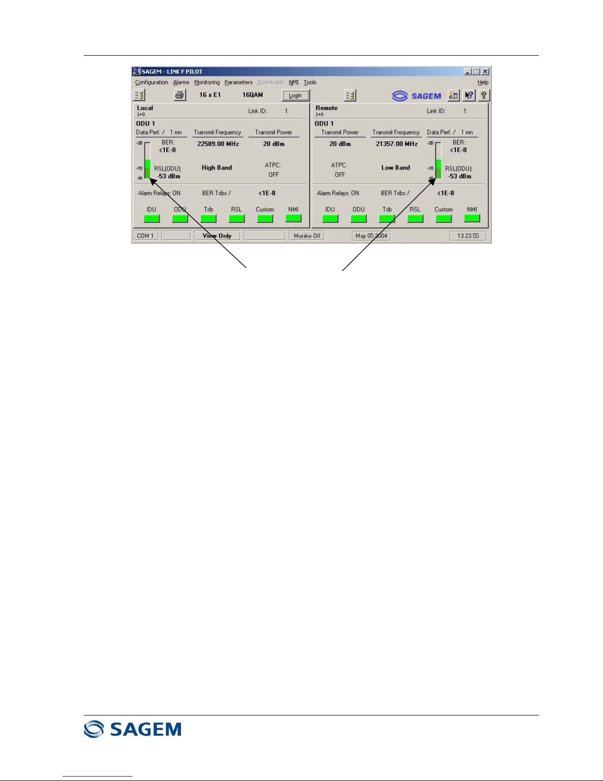
Receive Signal Levels should be similar on both ends
If there is more than 5 dB difference (with the same
transmit output power), check antenna alignment, ODUs,
IDUs, and antennas.
Figure 1.14 : Main Sagem Link F Pilot Screen
Page 23
SAGEM-LINK F 288055571-04
Installation and Operation Manual
Page 23/142
Issue 04 : July 2005
Reproduction and communication prohibited without the written permission of Sagem Communication
1.9 - Connecting IDU to External Equipments
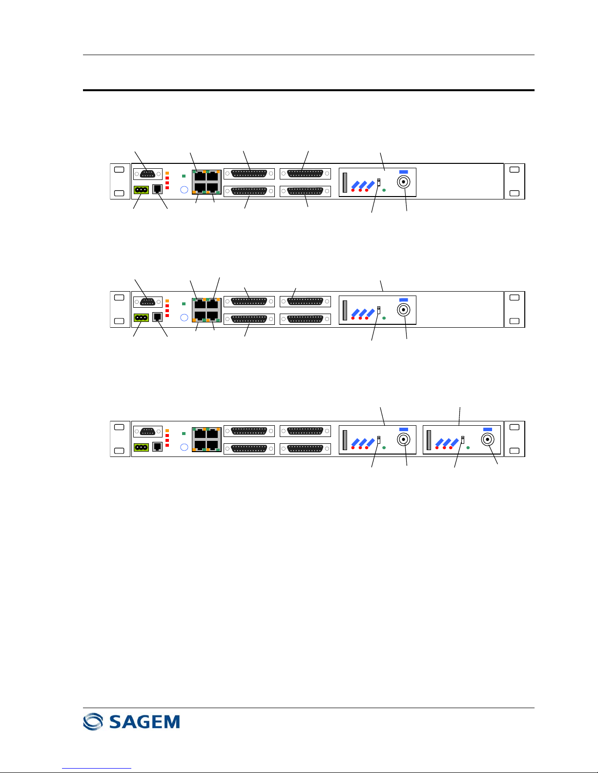
1.9.1 - IDU Front Panel Access Description
The following access are available at the IDU Front panel (See Figure 1.15) :
To Main
ODU
To Standby
ODU
Main Channel
On/Off Switch
Standby Channel
On/Off Switch
Cable Interface Module
(Main)
Cable Interface Module
(Standby)
IDU for 1+1 System
To ODU
DC Power In
On/Off Switch
To PC serial Port
EOW
Handset
SNMP
Manager
West
East
Tribs 1-4
Tribs 9-12
Tribs 5-8
Tribs 13-16
Cable Interface Module
IDU for 1+0 System (16 E1 version)
Maint
Mux
Tribs
Cust
Call
S
On
Off
POWER
To ODU
DC Power In
On/Off Switch
To PC serial Port
EOW
Handset
SNMP
Manager
100BaseT
West
East
Tribs 1-4
Tribs 5-8
Extra Trib
Cable Interface Module
IDU for 1+0 System (Ethernet version)
Maint
Mux
Tribs
Cust
Call
S
On
Off
POWER
Maint
Mux
Tribs
Cust
Call
S
On
Off
POWER
S
On
Off
POWER
Figure 1.15 – SAGEM LINK F IDU Front Panel for 1+0 and 1+1 Systems
• a power connection from a negatively biased DC source of between –36 VDC and -59 VDC,
labeled "Power",
• a point-to-point Engineering Order Wire RJ11 connection labeled "EOW",
• a PC port to connect a local craft terminal, via a DB 9 connector,
• Four Ethernet ports (RJ 45 connectors):
- 3 x 10 baseT Ports dedicated to Network Management Interface "Mgr", "West", "East"
(Ethernet hub),
- 1 x 100 baseT Port "100bT" (option)
• 16 x G703 2 Mbit/s tributary ports (4 tributaries per DB25 connector) in unbalanced 75 Ω mode, or
in balanced 120 Ω mode, the selection between modes is controlled by software :
Page 24
SAGEM-LINK F 288055571-04
Installation and Operation Manual
Page 24/142
Issue 04 : July 2005
Reproduction and communication prohibited without the written permission of Sagem Communication
- 16 E1 version : "Tribs 1-4", "Tribs 5-8", "Tribs 9-12", "Tribs 13-16".
- Ethernet version : : "Tribs 1-4", "Tribs 5-8", "Extra Trib",
Warning : the connector corresponding to tributaries 5 to 8 is not the same fo
r
16 E1 and Ethernet versions.
• One N connector per ODU connection "ODU".
• One ground connection ("Faston" connector).
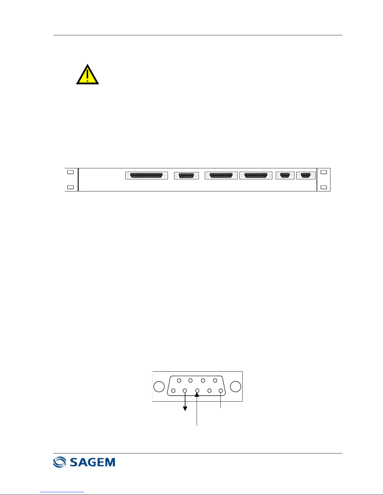
1.9.2 - IDU Rear Panel Access Description
The following access are available at the IDU Rear panel (See Figure 1.16)
MGMT2
Aux2
Aux1
MGMT1
AUX3
ALARM RELAYS & DRY LOOPS
Figure 1.16 – SAGEM LINK F IDU Rear Panel
The IDU rear panel provides the following interfaces :
• a DB37 connector labeled "ALARM RELAYS & DRY LOOPS" including terminal alarm relays, and
4 input output dry loops.
• a DB15 connector labeled "AUX3" corresponding to a 64 kbit/s auxiliary data channel with a V11
electrical interface, that can be configured in either co-directional or contra-directional mode,
• two "MGMT1" and "MGMT2" DB25 connectors: management ports, MGMT1 configurable in
synchronous V11 or asynchronous V28 mode and MGMT2 used in synchronous V11 mode
• two 9600 bit/s (max.) asynchronous digital auxiliary data channels "AUX1" and "AUX2" (DB9
connectors), with V11 or V28 electrical interface configurable by software.
1.9.3 - Connectors Pinout Description
Local Craft Terminal Connection
Local Craft Terminal connection is made via a serial access (DB9 connector). Connector Pinout is given
in Figure 1.17.
This is a DCE, V28 interface, compliant to EIA 574 standard.
1
5
96
Output Data
2
3
Input Data
Ground
Figure 1.17 - DB9 PC connector Pinout
Page 25

SAGEM-LINK F 288055571-04
Installation and Operation Manual
Page 25/142
Issue 04 : July 2005
Reproduction and communication prohibited without the written permission of Sagem Communication
Engineering Order Wire
The IDU female connector "EOW " (RJ11) provides connection to a telephone handset.
Pin Description
1 Microphone (input)
2 Earpiece (ground)
3 Earpiece (output)
4 Microphone (ground)
Figure 1.18 - Engineering Orderwire Connector Pinout
Note : Handset is provided as an option
Ethernet Ports
Four RJ45 Ethernet Ports are available : three of them are use for Network Management operation, the
fourth is dedicated to an optional 100 baseT transmission.
The ports "Mgr", "East" and "West" are part of an internal 10 baseT Ethernet hub, and can be connected
to other IDUs or to a SNMP manager. Note that in a network, it is necessary to limit the number of
cascaded hubs to 4.
The pinout of Ethernet Ports are given in Figure 1.19
10 base T (SNMP)
"West"
1 1
11
8
8
88
10 base T (SNMP)
"East"
10 base T (SNMP)
Manager
100 BaseT
(Ethernet Option only)
PIN No Signal name Description
1 TX_ETH_P Ethernet output (+)
2 TX_ETH_N Ethernet output (-)
3 RX_ETH_P Ethernet input (+)
4-NC
5-NC
6 RX_ETH_N Ethernet input (-)
7-NC
8-NC
Figure 1.19 – Ethernet Ports Pinout
Page 26

SAGEM-LINK F 288055571-04
Installation and Operation Manual
Page 26/142
Issue 04 : July 2005
Reproduction and communication prohibited without the written permission of Sagem Communication
E1 Tributaries Connections
The four DB25 connectors in IDU front panel correspond to four x 4 Input/output 2 Mbit/s access (E1).
When Ethernet option is installed, additional E1 tributaries can be used along with Ethernet interface.
Refer to chapter 6 for more information. Depending on configuration, up to 8 E1 tributaries can be
combined with Ethernet transmission.
If the configuration with Ethernet option corresponds to a 28 MHz channel in QPSK mode, or to a 14
MHz in 16QAM mode, then an extra E1 tributary is available. Note that this particular tributary is not
available for all other cases.
Tributary access are available in 120 Ω balanced mode, or in 75 Ω unbalanced mode. Impedance mode
is controlled by the Pilot software.
It is possible to have one connector configured in balanced mode, while the others are configured in
unbalanced mode.
It is not possible to have on the same DB25 connector two tributaries in a different mode.
Tributary connector pinout corresponding to tributaries 1 to 4 is given in Figure 1.20. The other tributary
connectors have the same pinout.
When Ethernet option is present and when the data rate corresponds to a 28 MHz channel in QPSK
mode, or to a 14 MHz in 16QAM mode, the extra tributary is available on the third connector (Pinout
equivalent as trib #1, the other pins are not connected)
Page 27

SAGEM-LINK F 288055571-04
Installation and Operation Manual
Page 27/142
Issue 04 : July 2005
Reproduction and communication prohibited without the written permission of Sagem Communication
Pin Signal 120 Ohm balanced 75 Ohm unbalanced
1 GND Ground Ground
14 TXHDB3P1 Transmit trib #1 - P Transmit trib #1
2 GND Ground Ground
15 TXHDB3N1 Transmit trib #1 - N
Grounded by the cable
3 RXHDB3P1 Receive trib #1 - P Receive trib #1
16 GND Ground Ground
4 RXHDB3N1 Receive trib #1 - N
Grounded by the cable
17 TXHDB3P2 Transmit trib #2 - P Transmit trib #2
5 GND Ground Ground
18 TXHDB3N2 Transmit trib #2 - N
Grounded by the cable
6 RXHDB3P2 Receive trib #2 - P Receive trib #2
19 GND Ground Ground
7 RXHDB3N2 Receive trib #2 - N
Grounded by the cable
20 TXHDB3P3 Transmit trib #3 - P Transmit trib #3
8 GND Ground Ground
21 TXHDB3N3 Transmit trib #3 - N
Grounded by the cable
9 RXHDB3P3 Receive trib #3 - P Receive trib #3
22 GND Ground Ground
10 RXHDB3N3 Receive trib #3 - N
Grounded by the cable
23 TXHDB3P4 Transmit trib #4 - P Transmit trib #4
11 GND Ground Ground
24 TXHDB3N4 Transmit trib #4 - N
Grounded by the cable
12 RXHDB3P4 Receive trib #4 - P Receive trib #4
25 GND Ground Ground
13 RXHDB3N4 Receive trib #4 - N
Grounded by the cable
Figure 1.20 – DB25 Tributary Connector Pinout
1
25
14
13
Page 28
SAGEM-LINK F 288055571-04
Installation and Operation Manual
Page 28/142
Issue 04 : July 2005
Reproduction and communication prohibited without the written permission of Sagem Communication
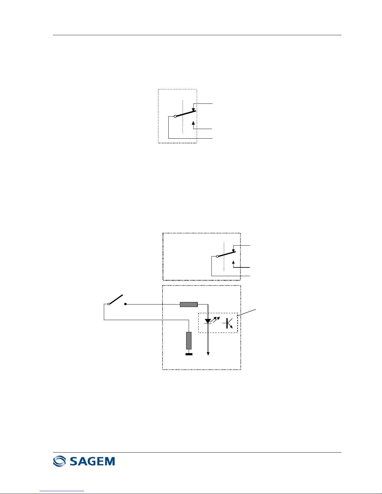
Alarm Relays and I/O Dry Loops
The rear panel DB37 connector includes
• 5 alarm relays : these alarms are managed by SAGEM LINK Pilot software. The electrical
interfaces for each alarm is given in Figure 1.21 :
Normally Open
Normally Closed
Common
Figure 1.21 – Alarm relay electrical interface
The alarm condition correspond to normally closed state of the relay.
NC= Normally Closed
NO= Normally Open
• 4 Inputs / Outputs dry loops: the electrical interface for each loop is given in Figure 1.20 :
LOOP INPUT_A
5 k
Ω
Photocoupler
-48V
5 k
Ω
LOOP INPUT_B
LOOP OUTPUT NO
LOOP OUTPUT NC
COMMON LOOP OUTPUT
SAGEM LINK
IINPUTS OUTPUTS
Figure 1.22 – I/O Dry Loop electrical interface
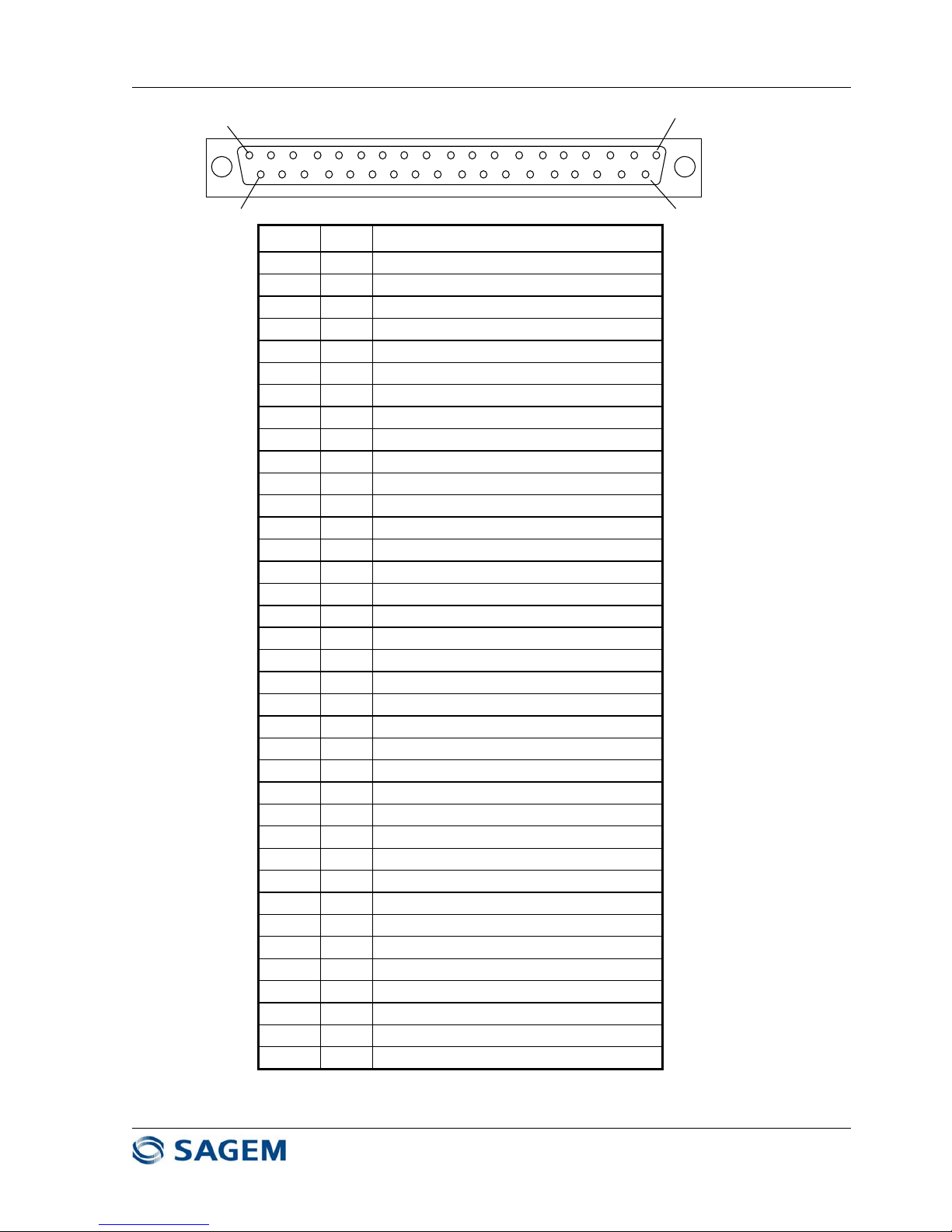
The pinout of DB37 connector is given in Figure 1.23
Page 29
SAGEM-LINK F 288055571-04
Installation and Operation Manual
Page 29/142
Issue 04 : July 2005
Reproduction and communication prohibited without the written permission of Sagem Communication
1
37
20
19
PIN # I/O Signal
1 - GROUND
20 I LOOP INPUT #1 – A
2 I LOOP INPUT #1 – B
21 I LOOP INPUT #2 – A
3 I LOOP INPUT #2 – B
22 I LOOP INPUT #3 – A
4 I LOOP INPUT #3 – B
23 I LOOP INPUT #4 – A
5 I LOOP INPUT #4 – B
24 O LOOP OUTPUT #1 NC
6 O COMMON LOOP OUTPUT #1
25 O LOOP OUTPUT #1 NO
7 O LOOP OUTPUT #2 NC
26 O COMMON LOOP OUTPUT #2
8 O LOOP OUTPUT #2 NO
27 O LOOP OUTPUT #3 NC
9 O COMMON LOOP OUTPUT #3
28 O LOOP OUTPUT #3 NO
10 O LOOP OUTPUT #4 NC
29 O COMMON LOOP OUTPUT #4
11 O LOOP OUTPUT #4 NO
30 O ALARM RELAY #1 NC
12 O COMMON ALARM RELAY #1
31 O ALARM RELAY #1 NO
13 O ALARM RELAY #2 NC
32 O COMMON ALARM RELAY #2
14 O ALARM RELAY #2 NO
33 O ALARM RELAY #3 NC
15 O COMMON ALARM RELAY #3
34 O ALARM RELAY #3 NO
16 O ALARM RELAY #4 NC
35 O COMMON ALARM RELAY #4
17 O ALARM RELAY #4 NO
36 O ALARM RELAY #5 NC
18 O COMMON ALARM RELAY #5
37 O ALARM RELAY #5 NO
19 - GROUND
Figure 1.23 – Alarm relays and I/O Dry Loop Connector Pinout
Page 30
SAGEM-LINK F 288055571-04
Installation and Operation Manual
Page 30/142
Issue 04 : July 2005
Reproduction and communication prohibited without the written permission of Sagem Communication
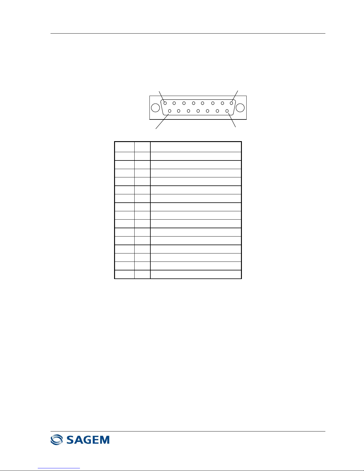
64 kbit/s Auxiliary Data Channel (AUX3)
The 64 kbit/s auxiliary data channel connector "AUX3" is available in a DB 15 connector on the rear
panel.
This data channel can be configured in a V11 co-directional mode (transmit clock given by the
external equipment) or in a V11 contra-directional mode (transmit clock given by SAGEM LINK F) :
Aux3 Connector pinout is given in Figure 1.24
1
8
9
15
Pin # I/O Signal
1 I Byte Timing Input (-)
9 I Transmit Data Input (-)
2 I Byte Timing Input (+)
10 I/O Transmit Clock (-)
3 O Byte Timing Output (-)
11 I/O Transmit Clock (+)
4 O Receive Data (+)
12 O Receive Clock (+)
5 O Receive Data (-)
13 O Receive Clock (-)
6 O Byte Timing Output (+)
14 - Ground
7 - Ground
15 - NC
8 I Transmit Data Input (+)
Figure 1.24 – Aux3 Data Channel Connector Pinout
Page 31

SAGEM-LINK F 288055571-04
Installation and Operation Manual
Page 31/142
Issue 04 : July 2005
Reproduction and communication prohibited without the written permission of Sagem Communication
9600 bit/s Auxiliary Data Channel (AUX1 & Aux2)
The 9600 bit/s auxiliary data channels "AUX1" and AUX2 are connected to two DB 9 connectors on
the rear panel.
This data channels can be configured either in a DCE V11 interface, or V28 interface (compliant to
EIA 574 standard). Depending on the interface, connector pinout is given on Figure 1.25
15
96
Pin # V11 Interface V28 Interface
1 Ground Ground
6NC NC
2 Output Data – (+) Output Data
7 Output Data – (-) NC
3 Input Data – (+) Input Data
8 Input Data – (-) NC
4NC NC
9NC NC
5 Ground Ground
Figure 1.25 – Aux1 or Aux2 Data Channel Connector Pinout
Serial Management Interface Ports MGMT1 and MGMT2
Serial management interface ports MGMT1 and MGMT2 are available in two DB25 connectors located
on the rear panel.
Data rate available : 9600 bit/s up to 115200 bit/s.
MGMT1 port can be configured in two modes :
- V11 synchronous mode (EIA 530)
- V28 asynchronous mode (ISO 2110)
MGMT1 port can be connected to a modem (RTS, CTS, DTR, DSR and DCD available).
MGMT2 port is not configurable, and is only available in V11 synchronous mode and X24/V11. When it
is used in X24 mode, this interface is a DCE type (terminal mode).
Connector pinout is given in Figure 1.26
Page 32

SAGEM-LINK F 288055571-04
Installation and Operation Manual
Page 32/142
Issue 04 : July 2005
Reproduction and communication prohibited without the written permission of Sagem Communication
1
25
14
13
Pin # V11 Mode V28 Mode (MGMT1 only)
1 Ground Ground
14 Transmit Data – (-) NC
2 Transmit Data – (+) Transmit Data
15 Transmit Clock – (-) NC
3 Receive Data – (+) Receive Data
16 Receive Data – (-) NC
4 NC Request to Send
17 Receive Clock (+) NC
5 NC Clear to Send
18 NC NC
6 NC DCE Ready
19 NC NC
7 Ground Ground
20 NC DTE Ready
8NC NC
21 NC NC
9 Receive Clock (-) NC
22 NC NC
10 NC NC
23 NC NC
11 NC NC
24 NC NC
12 Transmit Clock (-) NC
25 NC NC
13 NC NC
Figure 1.26 – MGMT1 and MGMT2 Management Ports Connector Pinout
Page 33

SAGEM-LINK F 288055571-04
Installation and Operation Manual
Page 33/142
Issue 04 : July 2005
Reproduction and communication prohibited without the written permission of Sagem Communication
Cable References for SAGEM LINK F
The cables which can be connected to the IDU front panel are shown in Figure 1.27.
To Other IDU
Ethernet straight or crossed cables
To PC /LT
To ODU
or
IDU to ODU c able
(Balanced or Unbalanced )
2 Mbit/s In/Out Cable
To Distribution Panel
Ethernet straight or crossed cable
To Network
Manager
(Network Management)
Telephone Handset
To DC Power
Source
Straight cable
Crossed cable
To modem
12 21
20
13
9
5 24 30
21
20
On
Of
f
POWER
Figure 1.27 – Cables for a Terminal Station – Front Panel
The cables which can be connected to the IDU rear panel are shown in Figure 1.28.
AUX3 Data Channel Cable
To Distribution
Panel
14
6
37
7
MGMT2
Aux2
Aux1
MGMT1
AUX3
ALARM RELAYS & DRY LOOPS
OR
To PC
15
T
o Distribution
Panel
Alarm Relays & Dry Loops Cable
To Distribution
Panel
O
R
To EOW 300
Figure 1.28 – Cables for a Terminal Station – Rear Panel
In a relay station IDU are connected "back to back". Typical connection is given on Figures 1.29 and 1.30
Page 34

SAGEM-LINK F 288055571-04
Installation and Operation Manual
Page 34/142
Issue 04 : July 2005
Reproduction and communication prohibited without the written permission of Sagem Communication
Transfer 2 Mbit/s In/Out Cable
36
Relay statio n Ethernet Cable
21
s
s
Figure 1.29 – Cables for a relay station – Front Panel
MGMT1-MGMT2 Trans fer Cable
19
Aux1/Aux2 Dat a ChannelTransf er Cable
8
Aux3 Data Channel Transfer Cable
18
Figure 1.30 – Cables for a relay station – Rear Panel
Table 1.1 indicates Sagem Part Number for all cables for this IDU (terminal or relay modes).
Figure
item
Drawing # Designation Length SAGEM P/N
2.5 m 55670225
9 55050152EA - DC Power cable 5 m 55670226
12 m 55670227
25 m 55670228
2.5 m 55670182
5 55050138EA
- 2 Mbit/s tributary 120 Ω In/Out cable
5 m 55670183
12 m 55670184
24.8 m 55670185
55670563EA
- 2 Mbit/s tributary 75 Ω In/Out cable
2.5 m 55670563-2M5
30 DB25 – 8 BNC-F 5 m 55670563-5M0
12 m 55670563-12M
25 m 55670563-25M
60 m 251043775
55670405EA
- 2 Mbit/s tributary 75 Ω In/Out cable
2.5 m 55670405-2M5
24 DB25 – 8 BNC-M 5 m 55670405-5M0
12 m 55670405-12M
25 m 55670405-25M
12 55050156EA
- PC/LT connection cable
1.5 m 55670223
3 m 55670224
13 55050184EA - Modem connection cable 1.5 m 55670340
3 m 55670341
2.5 m 55670342
14 55050185EA
- Aux3 data channel cable to disc. Panel
5 m 55670343
12 m 55670344
25 m 55670345
6 55050149EA - Aux3 - EOW 300 channel cable 1.5 m 55670221
3 m 55670222
Page 35

SAGEM-LINK F 288055571-04
Installation and Operation Manual
Page 35/142
Issue 04 : July 2005
Reproduction and communication prohibited without the written permission of Sagem Communication
Figure
item
Drawing # Designation Length SAGEM P/N
18 55050189EA - AUX3 data channel transfer cable 1.5 m 55670352
3 m 55670022
36 - Crossed 2 Mbit/s tributary transfer cable 2.5 m 251027429
2.5 m 55670215
7 55050150EA - Aux1/Aux2 - Data channel cable 5 m 55670216
to distribution panel 12 m 55670217
25 m 55670218
15 55670420EA - Aux1/Aux2 - PC connection cable 1.5 m 55670420-1M5
3 m 55670420-3M0
8 55050151EA - AUX1/AUX2 data channel transfer cable 1.5 m 55670219
3 m 55670220
2.5 m 251378024
37 251389233EA - Alarm relays and dry loops cable to 5 m 251378037
Distribution panel (DB37) 12 m 251378045
24.8 m 251378058
20 - Straight ETHERNET cable (NMI/NMI 1.5 m 55670421
transfer or to manager) 3 m 55670422
21 - Crossed ETHERNET cable (NMI/NMI 1.5 m 55670423
transfer or to manager) 3 m 55670424
19 55050190EA - MGMT1 - MGMT2 transfer cable 1.5 m 55670354
3 m 55670355
Table 1.1 – Cables Part Numbers
Page 36

SAGEM-LINK F 288055571-04
Installation and Operation Manual
Page 36/142
Issue 04 : July 2005
Reproduction and communication prohibited without the written permission of Sagem Communication
Chapter 2
Commissioning
2.1 - Overview
This chapter explains how to verify Sagem Link F correct operation after installation. Testing
procedures are given in order to check radio system is operating according to the specifications.
The tests performed are :
• Frequency Scan
• Receive Signal Level
• Tributary Tests
• Engineering Order Wire (optional)
• Alarm Relays and I/O Dry Loops Test (optional)
• 1+1 Verification (optional)
• BER measurement
Required test equipment
• Laptop Computer with a serial interface
• Sagem Link F Pilot software
• 2 Mbit/s Bit Error Rate Analyzer
• Digital voltmeter
Sagem Link F Field Commissioning Form
A field commissioning form is provided in order to record all measurement data and remarks during
commissioning operation.
Note
The Bit Error Rate tests are made only with the 2 Mbit/s signals. For IDU using Ethernet option, it will
be necessary to choose a configuration with at least one 2 Mbit/s tributary available. Refer to Chapter
6 for more details.
2.2 - Preliminary Verifications
Before beginning commissioning tests, it is necessary to check the following :
• Verify all equipment for damage occurred during installation
• Verify that all equipments are properly mounted
• Verify antenna polarization
• Check ODU, cable and IDU groundings
• Measure DC Input Voltage on each terminal and record it on the commissioning form
• Connect laptop computer to the PC DB9 connector on the IDU front panel, and run the Sagem
Link F Pilot software. Be sure to be logged in super user mode (Default password = 2345). On
the main screen verify and change if necessary :
- Local and Remote terminal transmit frequency
- Modulation type and Capacity
- Local and Remote terminal nominal transmit power, ATPC should be in “OFF” position
- Tributary Impedance
Page 37

SAGEM-LINK F 288055571-04
Installation and Operation Manual
Page 37/142
Issue 04 : July 2005
Reproduction and communication prohibited without the written permission of Sagem Communication
- Link ID Code
- If there is a tributary alarm, verify tributary inputs configuration and connections.
- If there are other alarms, or if the link does not work, refer to the troubleshooting section
in this manual
Note any discrepancy in the field commissioning form.
2.3 - Frequency Scan
A special function of the Pilot software is to measure and to record automatically the receive spectrum
around receive frequency. This operation is done on the local terminal only. During frequency scan
process, local transmitter is in mute position, so the link is not operating.
This measurement allows the user to measure interferer levels around receive frequency and to
display it graphically. A record of this measurement is stored in the flash memory, and can be
consulted after installation. In order to check interferer level at receive frequency, it could be
necessary to mute the remote transmitter.
Refer to frequency scan procedure in chapter 3 section 3.3.7.6.
Frequency scan is to be done separately on each end of the link.
Note in the commissioning form the presence of interferers close to the receive signal (adjacent and
second adjacent)
2.4 - Receive Signal Level
In normal weather conditions, the receive signal level depends on :
• Remote Transmit Power (tolerance : ± 2 dB)
• Remote and Local antenna gains (tolerance : ± 1 dB each)
• Free Space Path Attenuation
• Coupler Losses for a 1+1 Hot Stand By system, or flex guide losses for a remote mount system
Compare the actual receive signal level displayed on the main screen of the Pilot software, with the
expected signal level.
As the tolerances are:
• ± 2 dB for the transmit power
• ± 1 dB for the antenna gain (per antenna)
• ± 3 dB for the receive level measurement
• ± 0.5 dB for 1+1 coupler losses
If we want to compare the receive level displayed with the expected calculated receive level, it is
necessary to take in account the tolerances for each parameter :
For a 1+0 system, the worst case for this comparison is within ±7 dB (±2 ±1 ±1 ± 3). For most of the
cases, a typical tolerance is ±5 dB.
So, if the receive level displayed by the Pilot software is less than 5 dB compared to the calculated
receive level, it should be necessary to check again antenna alignment, a propagation problem or a
wrong polarization first. If there is still a problem on the receive level, replace ODU, then IDU, and if
necessary the antenna.
Record the measured receive signal level at each end of the link for each receiver.
Page 38

SAGEM-LINK F 288055571-04
Installation and Operation Manual
Page 38/142
Issue 04 : July 2005
Reproduction and communication prohibited without the written permission of Sagem Communication
2.5 - Tributary Tests
These tests are to be done on both ends of the link.
Using a BER analyzer with G821 capability, test all used 2 Mbit/s access.
BER Analyzer Settings :
• Transmit to Receive test
• 2 Mbit/s
• Internal Clock
• PRBS : 2
15
-1.
• 120 Ohm balanced, or 75 Ohm unbalanced depending on IDU configuration.
All used tributaries are to be tested one by one :
• Click on the button
(top left of the toolbar on main screen) or use the menu : "Tools /
Tributaries". The tributary screen appears.
• Verify that the tributary under test is configured in normal mode (N), with active service
(A), and no loopback (blank button).
• All other tributaries should be unconnected and configured as inverted (I)
• Normally there should be a local tributary alarm.
• Connect a 2 Mbit/s BER analyzer on the tributary input. Be sure to use a cable in the same
impedance (refer to "Interface" indication). The tributary alarm should be now cleared.
• Click on the loopback button to have access to loopback configuration screen, and select a
remote loopback for the tributary under test. (For loopback procedure refer to Chapter 3,
section 3.2.4).
• Verify on the BER analyzer that there is no error occurred during one minute
• Once the test has been done, disconnect the cable, and change Data alarm in invert mode
(I), and remove remote loopback for this tributary.
• Repeat this test for all used tributaries.
Page 39

SAGEM-LINK F 288055571-04
Installation and Operation Manual
Page 39/142
Issue 04 : July 2005
Reproduction and communication prohibited without the written permission of Sagem Communication
2.6 - Engineering Order Wire Test (optional)
If the handsets have been ordered, the following test is made to verify EOW proper operation. This
test requires the presence of people in local and in remote station. Connect handset in each IDU of
the link (RJ11 connector)
• From the local terminal press on the call button (PRESS). At the remote end the green led
corresponding to the EOW flashes. Verify that audio communication is operating properly
• Make the same test from the remote terminal.
2.7 - Alarm Relays and I/O Dry Loops Test (optional)
When alarm relays and I/O dry loops are used in the site, perform the following tests to verify proper
alarm operation.
This test is to be done on each end of the link.
Before starting the test verify that there is no alarm displayed in the equipment.
It is not possible to simulate all possible alarms without opening equipment : for instance, simulating a
Tx frequency alarm would require to open the ODU and to disturb externally the synthesizer phase
lock loop. However some alarms can be simulated with simple operations :
2.7.1 - Simulating an IDU Alarm
An IDU alarm could be easily simulated by entering a wrong Link ID code in the local terminal. This
wrong ID Code generates an IDU alarm, but does not affect modem or radio operation. To simulate an
IDU alarm :
• Remove DC Power on the local terminal, and disconnect IDU to ODU cable
• Power up the IDU, and change local ID Code.
• Switch off again DC power and connect IDU to ODU cable
• Switch on the IDU. Once the IDU is properly initialized, there should be an IDU alarm
displayed.
•
Once the test has been done, do not forget to write the right Link ID code using the same procedure.
2.7.2 - Simulating an ODU Alarm
An ODU alarm can be obtained by removing IDU to ODU cable. Prior to removing ODU cable, it is
necessary to switch off the cable interface module.
2.7.3 - Simulating a Tributary Alarm
A tributary alarm is obtained by changing the status of one tributary from normal (N) to invert (I), or
from invert to normal.
Once the test has been done, do not forget to restore the previous configuration.
2.7.4 - Simulating a RSL Alarm
To simulate a RSL Alarm, it should be necessary to diminish remote transmit power and to increase
RSL alarm threshold. (ATPC off).
Change the RSL alarm threshold to -60 dBm.
Page 40

SAGEM-LINK F 288055571-04
Installation and Operation Manual
Page 40/142
Issue 04 : July 2005
Reproduction and communication prohibited without the written permission of Sagem Communication
Decrease slowly remote transmit power in order to have a receive level below –60 dBm. Take care to
avoid to break the link, because in this case, it will not be possible to establish again communication
from the local terminal.
Once the test has been done, do not forget to restore previous settings.
2.7.5 - Simulating a Custom Alarm
To simulate a Custom alarm, configure " Local Aux1 Alarm" on the "Custom relay" (use the menu
Alarms / Config / Local, and select the IDU tab).
Then short circuit pins 2 and 20 of the DB37 connector (LOOP INPUT #1 – A and LOOP INPUT #1 –
B).
The alarm is displayed in the screen Alarm/View/Local - ALL tab. Verify that the alarm is cleared
when the loop is in open position.
2.7.6 - Testing Input Dry Loops
Affect " Local Aux1 Alarm", " Local Aux2 Alarm", " Local Aux3 Alarm" and " Local Aux4 Alarm" on the
Custom relay, and verify the alarm changes by short-circuiting or opening the loops.
2.7.7 - Testing Alarm Relays
For this test, it is necessary to use a multimeter to check continuity between contacts.
The three contacts of each relay are available in the DB 37 connector (see Figure 2.1) :
Normally Open (NO)
Normally Closed (NC)
Common
Figure 2.1 : Relay Contacts
When the IDU is not powered, the NC is connected to the Common, while the NO is in open position.
When the IDU is powered and when there is no alarm :
• NO is connected to Common
• NC is not connected to Common
When there is an alarm on the relay under test (use the above procedure to simulate alarms) :
• NC is connected to Common
• NO is not connected to Common
Simulate various alarms, and test the corresponding relays upon this procedure.
Page 41

SAGEM-LINK F 288055571-04
Installation and Operation Manual
Page 41/142
Issue 04 : July 2005
Reproduction and communication prohibited without the written permission of Sagem Communication
2.8 - 1+1 Verification (optional)
1+1 systems require additional tests compared to unprotected systems. These tests are made to verify
main and stand by units, and switches proper operation.
These tests are made on both sides of the link. As a remote switch control is not available for security
reasons, this test may require the presence of people on both sides of the link.
In hot standby mode, only one transmitter is active at a time. For a 1+1 system in frequency diversity
mode, both transmitter are active, and only receiver switchings are to be made.
In normal operation with revertive switching on, and without any alarms, the active transmitters and
receivers are the main units.
Du to the use of an asymmetrical coupler, the transmit power at antenna access and the receive
signal level at ODU access depend on the switches positions. For a 6 dB coupler, the difference
between the main and standby unit is around 5 dB.
In the figures below, active transmitter and receiver are written in bold characters.
Tx Main (L)
Rx Main (L)
Tx Standby (L)
Rx Standb y (L)
Tx Main (R)
Rx Main (R)
Tx Standby (R)
Rx Standby (R)
Figure 2.2 : Main local transmitter and receiver active
From the local terminal, connect a BER analyzer on a 2 Mbit/s tributary and make a remote loopback
for this tributary. There should not be any error during one minute.
From the local terminal in super user mode, select the menu "Tools/Diagnostic Tools/Equipment
Forcing" to access to the manual switching mode (refer to Chapter 3 section 3.3.7.2).
Select standby receiver by clicking on the Rx2 case, and validate.
Tx Main (L)
Rx Main (L)
Tx Standby (L)
Rx Standby (L)
Tx Main (R)
Rx Main (R)
Tx Standby (R)
Rx Standby (R)
Figure 2.3 : Main local transmitter and standby local receiver active
This switching should be error free. Wait one minute to verify the transmission is error free.
From the local terminal, in the same menu, select standby transmitter by clicking on the case "Tx2".
This switching causes errors. However the switching time should be less than 2 seconds (less than 2 x
10
6
errors).
Page 42

SAGEM-LINK F 288055571-04
Installation and Operation Manual
Page 42/142
Issue 04 : July 2005
Reproduction and communication prohibited without the written permission of Sagem Communication
Tx Main (L)
Rx Main (L)
Tx Standby (L)
Rx Standby (L)
Tx Main (R)
Rx Main (R)
Tx Standby (R)
Rx Standby (R)
Figure 2.4 : Standby local transmitter and receiver active
Clear the counter, and verify there is no error occurred during one minute.
If a revertive switch is used, from the local terminal select "Auto" for both transmitter and receiver.
Main local ODU should be now active.
If there is no revertive switch selected, select Rx1 and Tx1 in manual mode and validate. Then click on
the "Auto" cases.
The system is now in automatic mode, and the maintenance LED should be off.
Note : During transmitter switch from standby to main, errors are also generated.
Use the same procedure from the remote end of the link.
Page 43

SAGEM-LINK F 288055571-04
Installation and Operation Manual
Page 43/142
Issue 04 : July 2005
Reproduction and communication prohibited without the written permission of Sagem Communication
2.9 - BER Measurement
This test is to be done from one side of the link with all tributaries linked with a daisy chain
arrangement as described in Figure 2.5 and Figure 2.6.
In case of a problem due to an interferer, it should be necessary to measure the two directions
separately and to proceed to a frequency scan.
For a 1+1 system, as the verification of the different units have already been made, the quality test
shall be performed only with main channels (automatic mode).
A BER test using G821 parameters shall be performed for a duration depending on the network :
• 30 minutes for low capacity links (GSM, Wifi,…)
• 24 hours for medium and high capacity links
An other amount of time could be used for this test, but this will require Sagem approval.
Figure 2.5 : Link Quality Measurement
.
Page 44

SAGEM-LINK F 288055571-04
Installation and Operation Manual
Page 44/142
Issue 04 : July 2005
Reproduction and communication prohibited without the written permission of Sagem Communication
Figure 2.6 : Tributary daisy chain connections
The BER tester shall be configured as follows :
• 2 Mbit/s data rate, HDB3, with a 2
15
-1 sequence, using the same impedance than selected
in the IDU.
• Run the test for the required amount of time
• Depending on the BER tester used, results could be transferred electronically to the PC via
a serial port in a file. If it is not possible, the results shall be printed on paper.
Once all these tests have been completed, do not forget to remove tributary daisy chain arrangement.
The system is now ready to operate with traffic connected. If any test have failed to meet specifications,
consult the troubleshooting chapter in this manual.
2.10 - Recording Configuration Information
This procedure explain how to get all necessary information from SAGEM LINK F equipment to be
attached with Sagem Link F Field Commissioning Form.
Connect the computer to the local IDU and run the Sagem Link F Pilot software in super user mode
(default password : "2345")
Link Configuration Information :
From the main screen, open the menu "Configuration/Print", this screen appears :
Check all cases
Select File
Validate
Save the file in the PC using a name including site names :
Page 45

SAGEM-LINK F 288055571-04
Installation and Operation Manual
Page 45/142
Issue 04 : July 2005
Reproduction and communication prohibited without the written permission of Sagem Communication
"Name of local site – Name of Remote site.txt".
This file is a text file describing local and remote configuration, with information regarding hardware
and software involved (part numbers, manufacturing date, versions…).
Saving Local and Remote Configuration
Local and remote configurations can be saved in data files. In case of a replacement of a unit,
previous configuration can be restored easily.
To save local or remote configuration use the menu, :
"Configuration/Save as/Local or Remote". Chose a name for the configuration files like :
"Name of local site – Name of Remote site.slf", for the local terminal and
"Name of Remote site – Name of Local site.slf", for the remote terminal.
Page 46

SAGEM-LINK F 288055571-04
Installation and Operation Manual
Page 46/142
Issue 04 : July 2005
Reproduction and communication prohibited without the written permission of Sagem Communication
S
SAGEM LINK F
Field Commissioning Form
Page 1/2
Customer Information :
Link Name :
Date :
Terminal Configuration :
1+0 1+1 HSB 1+1 SD 1+1 FD
Capacity / Modulation :
2xE1 / QPSK 4xE1 / QPSK 8xE1 / QPSK
16xE1 / QPSK 8xE1 / 16QAM 16xE1 / 16QAM
Local Site Remote Site
Name : Name :
Antenna Type : Antenna Type :
IDU to ODU Cable Length : IDU to ODU Cable Length :
Transmit Frequency : Transmit Frequency :
TEST DATA
Local Site Remote Site
Input DC Voltage : VDC Input DC Voltage : VDC
RSL at ODU access (dBm) RSL at ODU access (dBm)
Measured Expected Difference Measured Expected Difference
Main Main
Standby Standby
Tributary Tests : Pass Fail Tributary Tests : Pass Fail
E.O.W. * : Pass Fail E.O.W. * : Pass Fail
Alarms & Loops* : Pass Fail Alarms & Loops* : Pass Fail
1+1 Operation* : Pass Fail 1+1 Operation* : Pass Fail
Bit Error Tests Bit Error Tests
Test Duration :
Number of Errors :
Pass Fail
* Note : Optional
Page 47

SAGEM-LINK F 288055571-04
Installation and Operation Manual
Page 47/142
Issue 04 : July 2005
Reproduction and communication prohibited without the written permission of Sagem Communication
S
SAGEM LINK F
Field Commissioning Form
Page 2/2
Attached Electronic Documents
Floppy Disk CDROM Other
Reference(s) :
Configuration information file from the menu "Configuration / Print"
Configuration file from the menu "Configuration / Save As / Local"
Configuration file from the menu "Configuration / Save As / Remote"
BER Measurement file
Other :
Notes
Page 48

SAGEM-LINK F 288055571-04
Installation and Operation Manual
Page 48/142
Issue 04 : July 2005
Reproduction and communication prohibited without the written permission of Sagem Communication
Chapter 3
Sagem Link F Pilot Description
3.1 - Overview
This chapter describes Sagem Link F Pilot software which is the Graphical User Interface used to
control all SAGEM LINK F operations. It provides information on using, starting and exiting the SLF
Pilot and on understanding all features.
First, all necessary operations to start and to configure a link are presented. In a second part of this
chapter all menus are described.
The SLF Pilot allows the user to :
• View local and remote terminal configuration
• Set and change parameters on local and remote terminals
• Monitor RSL, BER and alarms
• Download and activate a new firmware version
• Perform specific installation and maintenance operations
• Set network management configuration
Software environment
The SLF Pilot is run on a PC with the following minimum configuration :
• Operating System : Windows 2000 or Windows XP
• Pentium 4 or above, 1 GHz minimum
• Memory 256 Mbytes of RAM
• 50 Mbytes available on hard disk
• CD ROM drive
• One serial port COM1 to COM4 (or USB port + serial to USB adapter)
• A SVGA Screen, with 600 x 800 minimum resolution (16 colors minimum)
Note :
This chapter describes mainly SAGEM-LINK F Pilot software with nx2 Mbit/s IDUs. If Ethernet option
is installed, some screen may differ slightly. Refer to description in Chapter 6 for Ethernet version.
Page 49

SAGEM-LINK F 288055571-04
Installation and Operation Manual
Page 49/142
Issue 04 : July 2005
Reproduction and communication prohibited without the written permission of Sagem Communication
3.2 - SAGEM LINK F Pilot : Main Operations to Configure a Link
This section describes all operations to configure main parameters of Sagem Link F radios. Main topics
covered are :
• Installing the SAGEM-LINK F Pilot Software
• Connecting the laptop to SAGEM-LINK F IDU
• Link Preliminary configuration
• Completing Link Configuration
3.2.1 - Installing the SAGEM – LINK F Pilot Software
Insert SAGEM LINK F CD-ROM into the drive. SLF Pilot software is launched automatically, if the CDROM drive has been configured with the "Autorun" option.
If the program does not start automatically, use Windows Explorer and run the "setup.exe" file.
Installation is automatic, and does not require any manual configuration. SLF Pilot can be run by
double clicking on the shortcut.
Note : if the computer has no serial port available, it is necessary to use an USB-serial port adapter.
SAGEM LINK F Pilot application requires a COM port between 1 and 4. If you use a different COM
port, SAGEM LINK F equipment will not be recognized by the SLF Pilot.
In order to check what COM port has been affected by Windows after adapter installation, go to the
Control Panel / System / Hardware / Device Manager/Ports (COM & LPT) and click on the COM and
LPT icon.
Click with the right button on the icon corresponding to your USB – serial adapter, and select
"Properties". Then select the tab "Port Settings" and click on the button "Advanced".
On this screen you can see what COM port is currently used for the adapter.
If the adapter has been affected on a COM port which is not comprised between COM1 and COM4,
then change the COM port number to a number between 1 and 4. If there is not an available COM port
in this range, it should be necessary to disable one existing port and to affect it for the adapter.
3.2.2 - Connecting the Laptop to SAGEM – LINK F IDU
Connect the laptop to the "PC" port of a SAGEM LINK F IDU using a serial RS232 cable.
Main
IDU
Trib
Cust
S
On
Off
Call
PC
POW
EO
Mgr 100b
EastWest
TRIB 1-4 TRIB 5-8
TRIB 9- T RIB 13-
OD
POW
Serial Cable
Ref : 55 670 223 (1.5 m)
55 670 224 (3 m)
Page 50

SAGEM-LINK F 288055571-04
Installation and Operation Manual
Page 50/142
Issue 04 : July 2005
Reproduction and communication prohibited without the written permission of Sagem Communication
The IDU is connected to its ODU, and to a DC power supply. Switch on the IDU with the switch in front
panel and run the SAGEM LINK F Pilot software.
The following screen appears :
An IDU has been detected in COM1
Click on the OK button
When an IDU is detected, then the port, the IDU type, the software version and the serial numbers are
indicated on the first screen. In order to access to SLF Pilot main screen, click on the OK button.
If the following screen appears without any indication, then it means the equipment is not properly
connected, or not powered, or PC COM port is not properly configured.
No equipment detected
Click on the Rescan
button
Check if IDU is powered, if PC cable and COM settings are good, and click on the "Rescan" button.
3.2.3 - Link Preliminary Configuration
Page 51

SAGEM-LINK F 288055571-04
Installation and Operation Manual
Page 51/142
Issue 04 : July 2005
Reproduction and communication prohibited without the written permission of Sagem Communication
The first link configuration is made separately at each end of the link. If the link has been previously
established, then it is possible to configure dynamically parameters only from one side of the link.
The first essential parameters to configure before establishing the link are :
• Channel Transmit Frequency
• Modulation and Capacity
• Transmit Power (ATPC should be in "OFF" position at this time)
• Link ID Code
Note : When powering up terminal for the first time, transmitter should be in "MUTE" position, in order
to avoid any interference with other radios while configuring the equipments.
It is necessary to keep transmitter in mute position until transmit frequency, modulation and capacity
are properly configured.
When the link is not established, the main Pilot screen indicates "No remote radio" on the right side of
the screen. An example of a typical screen is given below :
View Only mode
Click here for login
Local terminal parameters are on the left part of the screen, while remote terminal parameters are
located on the right side.
On the top of the screen, current capacity and modulation are displayed. Below are terminal
configuration and Link ID code.
On the middle part of the screen BER indication, Receive Signal Level (RSL), Transmit frequency,
Transmit Power, and ATPC status are indicated.
On the bottom of the screen, main alarms are displayed.
Page 52

SAGEM-LINK F 288055571-04
Installation and Operation Manual
Page 52/142
Issue 04 : July 2005
Reproduction and communication prohibited without the written permission of Sagem Communication
Click on the "Login" button and enter the password "1234" corresponding to a user level or "2345"
corresponding to a super user level (default passwords).
Validate by clicking on the OK button.
The main screen with a super user login is given below. Some button are now present. Each button
allows the user to modify a specific parameter.
Note that only one change at a time is allowed.
When changing a parameter, use the button
to validate the change, or the button to
cancel.
By default, a warning screen appears to confirm again the choice.
Page 53

SAGEM-LINK F 288055571-04
Installation and Operation Manual
Page 53/142
Issue 04 : July 2005
Reproduction and communication prohibited without the written permission of Sagem Communication
For advanced users who may want to remove this confirmation, use the menu Configuration /
Settings and uncheck "Always confirm choice"
While transmitter is still in mute position, change if necessary :
• Transmit frequency by moving the cursor on the slide
, or by clicking on the left
or right buttons, and validate
• Capacity
Select capacity and validate
Click here to modify current Capacity
Click here to modify current
modulation scheme
Note : as capacity ranges are not the same in QPSK mode (2xE1, 4xE1, 8xE1 or 16xE1) than in
16QAM mode (8xE1 or 16xE1), it should be necessary to change first modulation then capacity or the
opposite depending on the current and target configurations.
• Modulation (only if 16QAM option is installed) : click on the modulation button (toggle between
QPSK and 16QAM.
Page 54

SAGEM-LINK F 288055571-04
Installation and Operation Manual
Page 54/142
Issue 04 : July 2005
Reproduction and communication prohibited without the written permission of Sagem Communication
• Link ID Code : this code is used to identify the link and to avoid data recovery from an other
link at the same frequency. Link ID Code of the local and remote terminals must be the same.
Once these settings are completed, remove the mute by clicking on the transmit power slide, and
select the wanted transmit power. Verify that ATPC is still in "OFF" position.
The terminal is now ready for transmission, it is necessary to repeat the same operations with the
remote terminal to establish the link.
Normally, if main parameters are compatible and if there is enough receive level, the link should be
established, and the main Pilot screen of the local terminal should look like that :
Main Pilot Screen for a 1+0 Configuration
Page 55

SAGEM-LINK F 288055571-04
Installation and Operation Manual
Page 55/142
Issue 04 : July 2005
Reproduction and communication prohibited without the written permission of Sagem Communication
Main Pilot Screen for a 1+1 Configuration
Note : Depending on the previous configuration, some alarms may still be present (Trib or Custom).
3.2.4 - Completing Link Configuration
Once the link has been established with the right main parameters, it is necessary to complete the
installation. The remaining parameters to adjust are :
• Local and remote tributaries configuration (alarms, impedance)
• Site names
• BER counting period
• Setting Alarm thresholds (BER, RSL)
• Alarm relays configuration
• Auxiliary channels configuration
• Automatic Transmit Power Control (ATPC)
• Network Management Interface Parameters (if available)
3.2.4.1 - Tributary Configuration
Click on the button
(top left (local) or top right (remote) of the toolbar on main screen) or use
the menu "Tools / Tributaries / Local or Remote" to open tributary configuration window.
This screen may vary depending on the current capacity. Below is an example for 16xE1 capacity.
Page 56

SAGEM-LINK F 288055571-04
Installation and Operation Manual
Page 56/142
Issue 04 : July 2005
Reproduction and communication prohibited without the written permission of Sagem Communication
When this button is "ON", an AIS signal
is transmitted when BER > BER
Threshold Alarm
I : the access is not currently used (Invert)
N : The tributary is used (Normal)
A
active (normal)
S
: AIS emission
BAL 120 : The DB25 Connector
Corresponding to this group
of 4 tributaries is in Balanced
120 Ohm configuration
Unbal 75 : The DB25 Connector
Corresponding to this group of 4
tributaries is in
Unbalanced 75 Ohm configuration
Blank : No Loopback
L : Local trib loopback
R : Remote trib Loopback
Change the different settings by clicking on the corresponding button.
• AIS on BER : when selected, an AIS is sent to the tributary output in case of a BER greater
than 10
-3
.
• Data Alarm :
• if the tributary is not currently used for traffic, then it is necessary to configure it as inverted
(I). In this mode, there will be no tributary alarm for this particular tributary if it is not
connected. However, if this tributary is connected while being in "I" position, a tributary
alarm is generated.
• If the tributary is used for traffic, it is necessary to configure it as normal "N". In this mode
there is an alarm in case of lack of signal at tributary input.
• Service : for normal service select "A" (active). If you select "S", an AIS is returned to the
receive tributary on the local terminal (this AIS is not being transmitted on the remote terminal).
• Loopback : when clicking on a button located on the loopback line, the following screen
appears :
Page 57

SAGEM-LINK F 288055571-04
Installation and Operation Manual
Page 57/142
Issue 04 : July 2005
Reproduction and communication prohibited without the written permission of Sagem Communication
Click on a case for
a local Tributary
loopback
Click here for a local
Multiplexer loopback
Click on a case for
a remote Tributary
loopback
Click here for a remote
Multiplexer loopback
Click here to Apply
From this screen it is possible to control a local or a remote tributary loopback, or a local or remote
multiplexer loopback.
Tributary Loopback
When a tributary loopback has been selected, then a Maintenance indication is written on the status
bar of the main Pilot screen, and the yellow LED "Maint" in IDU front panel flashes.
Local Tributary
loopback #1
has been selected
Page 58

SAGEM-LINK F 288055571-04
Installation and Operation Manual
Page 58/142
Issue 04 : July 2005
Reproduction and communication prohibited without the written permission of Sagem Communication
The local and remote loopback operations are explained in the diagram below :
Tributary Input
Local Terminal
Tributary Output
Remote Terminal
Tributary Input
Tributary Output
Local Tributary
Loopback
Tributary Input
Tributary Output
Remote Tributary
Loopback
Tributary Input
Tributary Output
A local tributary loopback is used to check a connection to the local terminal. A remote tributary
loopback is used to check link transmission.
Multiplexer Loopback
A Multiplexer Loopback is a loopback at multiplexer level (aggregate data rate). All input traffic is
returned to the output.
Multiplexer loopbacks work in the same way as tributary loopbacks. These loopback are used to
controlled multiplexer proper operation.
• Interface : Each DB25 connector including 4 tributary Input / Output, can be configured as
balanced 120 Ohm interfaces, or as unbalanced 75 Ohm interface. Click on the corresponding
button and validate the change.
3.2.4.2 - Entering Site Names
When logged as a user or a super user, enter a site name for the local terminal or for the remote
terminal
Click here to enter
the site name
3.2.4.3 - Configuring BER Counting Period
Page 59

SAGEM-LINK F 288055571-04
Installation and Operation Manual
Page 59/142
Issue 04 : July 2005
Reproduction and communication prohibited without the written permission of Sagem Communication
The BER counting period can be adjusted by clicking on Data Perf buttons or on the BER Tribs
buttons.
The following dialog box appears :
Choose a time interval and validate.
• Use the Reset button to clear BER counter and to start a new measurement.
• A BER counting period modification does not reset automatically the BER Counter. The errors
are recorded over a 24 hours period in IDU memory. When choosing a period, only errors
occurred in the selected duration prior to the request are displayed.
3.2.4.4 - Setting the Alarm Thresholds
BER and RSL alarms thresholds can be adjusted with the Pilot software.
BER thresholds : use the menu Alarms / Config / Local, and select the IDU tab. Two BER
thresholds are available : BER Warning (default : 10
-6
) and BER Alarm (default 10-3)
Note these thresholds may be modified (between 10
-3
and 10-6). Unless specific requirement, it is
advised to keep the default threshold figures.
BER Warning
:
Choose Threshold
(default 10
-6
)
BER Alarm
:
Choose Threshold
(default 10
-3
)
RSL threshold : use the menu Alarms / Config / Local, and select the ODU tab.
The receive level threshold must be within –60 dBm to –80 dBm range (default : -70 dBm).
Page 60

SAGEM-LINK F 288055571-04
Installation and Operation Manual
Page 60/142
Issue 04 : July 2005
Reproduction and communication prohibited without the written permission of Sagem Communication
RSL Threshold
Choose
Threshold between
-60 and -80 dBm
3.2.4.5 - Setting the Custom Alarm Relay
A custom alarm is available and can be used to monitor internal or external alarms. The following
screen explains how to configure this alarm.
Affect Local Loop 1
on
custom Alarm Relay
Enter an Alarm name
Validate
Once the custom alarm relay has been configured, the following message appears :
Page 61

SAGEM-LINK F 288055571-04
Installation and Operation Manual
Page 61/142
Issue 04 : July 2005
Reproduction and communication prohibited without the written permission of Sagem Communication
Click on the Yes button to activate the relays, or on the No button to disable the relays. In this case,
alarm relays color in main Pilot screen become blue.
3.2.4.6 - Configuring the Auxiliary Channels AUX1, AUX2 and AUX3.
On the main Pilot screen go to the menu Tools / Config Tools / Equipment Settings/ Local.
Select AUX 3
Interface
Select V11 or V28
Interface
Note : Connector pinout could vary depending on the selected option (refer to chapter1 description).
3.2.4.7 - Configuring the Automatic Transmit Power Control (ATPC).
ATPC is a process which is used to limit transmit power to the minimum necessary while having a
good transmission. When ATPC is selected for equipments in a network working in the same
frequency band, it allows to increase density and frequency re-use.
ATPC must not be active during antenna alignment process.
ATPC settings depend on the structure of the network (frequency re-use, interferers, link margin).
The operator has to define three main parameters :
• Maximum ATPC transmit power
• Minimum ATPC transmit power
• ATPC receiver threshold
Minimum and maximum ATPC transmit powers must be within transmitter power range, and
Maximum ATPC Transmit power – Minimum ATPC Transmit Power ≤ 20 dB.
ATPC threshold must be within –50 dBm to –80 dBm range.
The ATPC process consists of reducing transmit power as low as possible within the specified
range, without having errors on the remote end, and without having a remote receive level lower
than the ATPC threshold.
To activate ATPC click on the ATPC button on main Pilot screen. The ATPC button indication is
"ON" when ATPC works, or "OFF" when ATPC is disabled.
To configure ATPC, use the menu Tools/Config Tools/ATPC/ Local (or Remote)
Page 62

SAGEM-LINK F 288055571-04
Installation and Operation Manual
Page 62/142
Issue 04 : July 2005
Reproduction and communication prohibited without the written permission of Sagem Communication
Enter the three parameters and validate with the OK button.
Note : ATPC with 1+1 Hot Standby Systems
In 1+1 HSB systems, ATPC parameters are defined at antenna access. As in most cases, the 1+1
HSB coupler is not symmetric, the transmit power at antenna access depends on the transmitter
which is in traffic.
ATPC settings are defined at antenna access for the main ODU (ATPC transmit power at antenna
access = Main ODU Transmit Power – Coupler Losses.
3.2.4.8 - Configuring the Interleave
If the network requires a low transfer time, it should be necessary to inhibit interleaver features.
Transfer time depend on the data rate. Typical transfer time figures with or without interleaver are
given in the table below :
Capacity Interleaver on Interleaver off
2xE1 5 ms 1.6 ms
4xE1 2.5 ms 0.8 ms
8xE1 1.25 ms 0.4 ms
16xE1 0.62 ms 0.2 ms
To configure the interleaver use the menu Tools / Interleaver. The following dialog box appears :
ON : The interleaver is enabled
OFF : The interleaver is disabled
Click on the ON/OFF button to configure the interleaver and validate by clicking on the OK button.
Note : if there is no problem with the transfer time, keep the interleaver enabled. This will improve
error correction especially if burst errors occur.
Page 63

SAGEM-LINK F 288055571-04
Installation and Operation Manual
Page 63/142
Issue 04 : July 2005
Reproduction and communication prohibited without the written permission of Sagem Communication
3.2.4.9 - Configuring the 1+1 Operation
Static Phase Adjust
(Space or Frequency Diversity only)
Systems working in space diversity, or frequency diversity, may require a static phase adjust, in order
to compensate the static delay due to the path difference. For hot stand by systems using the same
antenna, this adjustment is not required.
To make a static phase adjust, select the menu : Tools/Diagnostic Tools/Equipment Configuration,
and the following windows appears :
Click on the static phase adjust button to initiate static phase adjustment on the terminal.
Revertive Automatic Switching
When this option is selected, the transmitter and the receiver in traffic are those from the main ODU. If
there is a fault on the main ODU (or on the main cable interface), then the switch select automatically
the standby transmitter or receiver. When the fault is cleared, there is an automatic return to the main
ODU.
This feature is useful when using an asymmetrical coupler for ODU coupling.
When this option is not selected, transmit switch and receive switch position stay on the current
position until a fault appears on the transmitter or on the receiver.
Note that transmit and receive switches are independent.
Page 64

SAGEM-LINK F 288055571-04
Installation and Operation Manual
Page 64/142
Issue 04 : July 2005
Reproduction and communication prohibited without the written permission of Sagem Communication
3.3 - SAGEM-LINK F Pilot : Menus Description
This section describes all available menus of SAGEM-LINK F Pilot software in super user mode.
• Configuration Menu
• Alarms Menu
• Monitoring Menu
• Parameters Menu
• Downloads Menu
• NMI Menu
• Tools Menu
3.3.1 - Configuration Menu
When clicking on the Configuration menu, this screen appears :
Click here to open a configuration file
Click here to save a configuration file
Click here to print configuration information
Click here to configure COM Ports or to
remove confirmation message
3.3.1.1 - Opening a configuration file
All configuration settings can be saved within a file. When opening such files all configuration
parameters are recalled. It is useful to save time in case of IDU replacement.
3.3.1.2 - Saving a configuration file
This menu allows the user to save local or remote terminal configuration into a file.
Click here to save local terminal configuration
Click here to save remote terminal configuration
Note : Always use a .slf extension for these configuration files.
Page 65

SAGEM-LINK F 288055571-04
Installation and Operation Manual
Page 65/142
Issue 04 : July 2005
Reproduction and communication prohibited without the written permission of Sagem Communication
3.3.1.3 - Print
This menu allows the user to print on paper or in a file all configuration data of the link :
Check appropriate cases
Select Printer or File
Validate
This file includes configuration data, hardware and software details for local and remote terminals.
3.3.1.4 - Configuration Settings
This menu allows the user to specify the COM ports to be scanned when connecting the SAGEMLINK F to a PC, and to remove confirmation message :
Click here to remove confirmation message
Choose the COM ports
to be scanned
When the "Always Confirm choice" is enabled, then the following confirmation message appears :
Page 66

SAGEM-LINK F 288055571-04
Installation and Operation Manual
Page 66/142
Issue 04 : July 2005
Reproduction and communication prohibited without the written permission of Sagem Communication
3.3.2 - Alarms Menu
When clicking on the Alarms menu, this screen appears :
Alarms View
Choose Local or Remote
Alarms Configuration
3.3.2.1 - Alarms Configuration - IDU
When Clicking on the "Alarms / Configuration /Local (or Remote)" menu the following screen
appears :
BER Warning
:
Choose Threshold
(default 10
-6
)
BER Alarm :
Choose Threshold
(default 10
-3
)
Rename External
Alarm
Affect internal or
external Alarms
to custom relay
9
9
9
9
9
9
9
9
Green = no alarm
Red = alarm
This first screen (IDU Tab) allows the user to :
• Set the BER Warning and BER Alarm thresholds (default 10
-3
and 10-6)
• Affect internal and external alarms to the custom relay
• Rename some external alarms
SAGEM-LINK F can manage up to 4 local external alarms and 4 remote external alarms.
The 4 remote alarms are also available in the local terminal with dry loop interface (3 relay contacts).
Page 67

SAGEM-LINK F 288055571-04
Installation and Operation Manual
Page 67/142
Issue 04 : July 2005
Reproduction and communication prohibited without the written permission of Sagem Communication
3.3.2.2 - Alarms Configuration - Trib
When Clicking on the Trib Tab of the Alarm Configuration menu, the following screen appears :
Affect tributary
Alarms
to custom relay
9999
9999
This screen allows the user to affect one or several tributary alarms to the custom relay.
3.3.2.3 - Alarms Configuration - ODU
When Clicking on the ODU Tab of the Alarm Configuration menu, the following screen appears :
Affect ODU
Alarms
to custom relay
9999
9999
Set Receive Level
Threshold Alarm
(-60 to -80 dBm)
This screen allows the user to affect one or several ODU alarms to the custom relay, and to set the
value of receive threshold alarm.
Note that RSL threshold alarm must be within –60 dBm to –80 dBm range.
Page 68

SAGEM-LINK F 288055571-04
Installation and Operation Manual
Page 68/142
Issue 04 : July 2005
Reproduction and communication prohibited without the written permission of Sagem Communication
3.3.2.4 - Alarms View (local or remote)
When Clicking on the "Alarms / View /Local (or Remote)" menu the following screen appears. Select
the IDU, ODU, Trib, RSL, Custom, NMI tab to view specific alarms, or select the All alarms tab to have
a complete alarm view.
It is possible to access directly to the same menus from the main Pilot screen by clicking on the
buttons corresponding to the alarms
(bottom of the
screen).
Green = no alarm
Red = alarm
Alarm View – IDU tab
Alarm View – All Alarms tab
Page 69

SAGEM-LINK F 288055571-04
Installation and Operation Manual
Page 69/142
Issue 04 : July 2005
Reproduction and communication prohibited without the written permission of Sagem Communication
Alarms Description
ODU Alarms
ODU PSU : Power Supply Alarm returned from the ODU. This alarm is active when there is a
default in the ODU power supply, or when the DC input voltage at ODU input is too
low. In case of an ODU alarm, check DC Power supply, and cable losses.
ODU Cable : ODU Cable Alarm is generated by the ODU in case of a transmit IF level below
the limit. In case of an ODU Cable alarm, check IDU to ODU cable losses.
Transmit Power : A transmit Power alarm is generated by the ODU in case of a transmitter
AGC loop fault, or in case of a transmitter mute set by the operator (in 1+1 system
when both transmitters are in mute position)
Transmit Frequency : This alarm is generated in case of IF or RF transmit synthesizer faults.
When this alarm is active, transmitter is also in mute position.
Receive Frequency : This alarm is generated in case of IF or RF receive synthesizer faults.
Receive Level : This alarm is generated when receive signal level is below the receive
threshold (default -70 dBm).
Tributary Alarms : a tributary alarm is generated when there is a lack of input signal for a tributary
configured as "normal" (N), or when there is a input signal for a tributary configured as
"inverted" (I). In case of a tributary alarm, check the corresponding cable, and verify
that external equipment is properly connected.
IDU Alarms
Warning 1+1 : A 1+1 warning is generated when the main or the standby units (ODU or cable
interface module) is not working properly (alarm or absent).
ID Code : When local and remote ID Code do not match, there is an ID Code alarm generated,
and there is a AIS emission on the receive data from the remote terminal. To clear this
alarm change the ID Code on one terminal.
IDU : This alarm is active in case of an IDU fault, or in case of problem to recover receive data.
BER Warning : This warning is generated when BER is greater than the BER warning
threshold (default 10
-6
)
BER Alarm : This alarm is generated when BER is greater than the BER alarm threshold
(default 10
-3
)
Local Aux In Alarms : These alarms represent local terminal input dry loop status.
Remote Aux In Alarms : These alarms represent remote terminal input dry loop status.
Page 70

SAGEM-LINK F 288055571-04
Installation and Operation Manual
Page 70/142
Issue 04 : July 2005
Reproduction and communication prohibited without the written permission of Sagem Communication
Cable Interface (modem) Alarms
Demodulation : This alarm is generated if there is a demodulator fault or if received data is not
recovered.
Modulation : This alarm is generated if there is modulator fault. When a modulation alarm
occurs, the transmitter is muted.
NMI (Network Management Interface) Alarms
Eth : This alarm is generated in case of a hardware failure regarding NMI Ethernet interface
ICC : This alarm is generated if there is a communication problem between the Network
management agent and the IDU microprocessor.
MGMT1 : This alarm is generated in case of a communication problem on MGMT1 serial port.
MGMT2 : This alarm is generated in case of a communication problem on MGMT2 serial port.
TSL2 : This alarm is generated in case of a communication problem between the two IDUs of
the link (when the link is broken for instance).
Page 71

SAGEM-LINK F 288055571-04
Installation and Operation Manual
Page 71/142
Issue 04 : July 2005
Reproduction and communication prohibited without the written permission of Sagem Communication
3.3.3 - Monitoring Menu
When clicking on the Monitoring menu, this screen appears :
Click here to display
Monitor.log file (text file)
Using Windows Notepad.exe
Click here to edit
Monitor list and to start a
new record
Click here to disp lay
Graphical log
Two Logs are available in SAGEM-LINK F equipments : the monitor log, which periodically record on
the PC hard disk the status of selected events, and the equipment events log which store in the
equipment RAM all events in case of status change.
Monitor log requires to have the PC connected to the SAGEM-LINK F during the whole measurement
time, while equipment event log works without any PC connected.
3.3.3.1 - View Monitor Log
When Clicking on the View Monitor Log, SAGEM-LINK F Pilot starts the Windows Notepad to display
Monitoring file.
This text file contains :
• Equipment information
• Monitoring parameters selected by the Edit Monitor Log control, with their status when starting
monitoring.
• Link monitoring data
As this is a text file, it could be printed or exported to an other program.
Monitoring Messages
Each alarm name is followed by the alarm source: LOCAL for any local alarm and REMOTE for
any remote alarm.
"Normal" means there is no alarm, while an "alarm" indication means an active alarm
Ex : "Transmit Freq 2 REMOTE Alarm" means there is an active transmit frequency alarm in the
transmitter 2 (standby unit) of the far end equipment.
Alarm List
Transmit Power 1 : Transmit power alarm on transmitter 1 (main)
Transmit Power 2 : Transmit power alarm on transmitter 2 (Standby)
Transmit Freq 1 : Transmit frequency alarm on transmitter 1 (main)
Transmit Freq 2 : Transmit frequency alarm on transmitter 2 (standby)
Receive Level 1 : RSL alarm on receiver 1 (main)
Receive Level 2 : RSL alarm on receiver 2 (Standby)
PSU 1 : ODU Power Supply alarm 1 (main)
PSU 2 : ODU Power Supply alarm 2 (standby)
Cable 1 : ODU Cable alarm 1 (main)
Page 72

SAGEM-LINK F 288055571-04
Installation and Operation Manual
Page 72/142
Issue 04 : July 2005
Reproduction and communication prohibited without the written permission of Sagem Communication
Cable 2 : ODU Cable alarm 2 (standby)
Modulation 1 : Modulator alarm on channel 1 (main)
Modulation 2 : Modulator alarm on channel 2 (standby)
Demodulation 1 : Demodulator alarm on channel 1 (main)
Demodulation 2 : Demodulator alarm on channel 2 (standby)
Link ID Code : Link ID Code alarm
IDU : IDU alarm
BER Warning
BER Alarm
Local Aux Input k : Alarm on auxiliary input k on local equipment (k = 1 to 4)
Remote Aux Input n : Alarm on auxiliary input n on remote equipment (n = 1 to 4)
Tributary i Fault : Alarm on tributary i (i= 1 to 16)
Measurements List
RSL Channel 1 - xx dBm : RSL on channel 1 (main) equal to - xx dBm
RSL Channel 2 - xx dBm : RSL on channel 2 (standby) equal to - xx dBm
BER Channel 1 nE-m : Bit error rate on channel 1 equal to nx10
-m
BER Channel 2 nE-m : Bit error rate on channel 2 equal to nx10
-m
G.821 Quality Data
Period 1mn/15mn/30mn/60mn/24h : G.821 data measuring period
G821 – ES xx : number of errored seconds
G821 – IS xx : number of unavailable seconds
G821 - SES xx : number of seriously errored seconds
G821 - IP xx : number of unavailable periods
G821 - ESR xx % : rate of errored seconds over the measuring period (indicated
above)
G821 - SESR xx % : rate of seriously errored seconds over the measuring period
(indicated above)
G821 - ISR xx % : rate of unavailable seconds over the measuring period
(indicated above)
G.826 Quality Data
Period 1mn/15mn/30mn/60mn/24h : G.826 data measuring period
G826 - ES xx : number of errored seconds
G826 - SES xx : number of seriously errored seconds
G826 - BBE xx : number of residual errored blocks, i.e. errored blocks coming
outside the seriously errored seconds (SES)
G826 - ESR xx % : rate of errored seconds over the measuring period (indicated
above)
G826 - SESR xx % : rate of seriously errored seconds over the measuring period
(indicated above)
G826 - BBER xx % : rate of residual errored blocks over the measuring period
(indicated above)
Events that may occur during monitoring
LOCAL-REMOTE(TSL) Broken/Restored : radio link broken/restored,
IDU-ODU(DCC) Broken/Restored : Communication link between IDU and ODU broken/restored,
TRANSMISSION Channel 1/Channel 2 : channel 1/channel 2 radio transmitter switch,
RECEPTION Channel 1/Channel 2 : channel 1/channel 2 radio receiver switch,
The connection with SAGEM-LINK F
Equipment is broken / restarted
: PC does not communicate with equipment any
more
3.3.3.2 - Edit Monitor List
When Clicking on the Edit Monitor List menu, the following screen appears :
Page 73

SAGEM-LINK F 288055571-04
Installation and Operation Manual
Page 73/142
Issue 04 : July 2005
Reproduction and communication prohibited without the written permission of Sagem Communication
Monitor Stopped : no monitoring in progress
Monitor Running : Monitoring in progress
Enter start and stop time
Select events to monitor
Enter monitoring start and stop date. This recording is only limited by the hard disk capacity. Be sure
to have enough capacity on disk before starting a monitor log.
Then select the events you would like to monitor by clicking successively on the ODU, IDU, Tribs and
Perf tabs.
ODU alarms
IDU alarms
Page 74

SAGEM-LINK F 288055571-04
Installation and Operation Manual
Page 74/142
Issue 04 : July 2005
Reproduction and communication prohibited without the written permission of Sagem Communication
Tributary Alarms
Click here to define the
time interval
Setting the time interval and the quality parameters
Once all parameters have been defined SAGEM LINK F Pilot will proceed to a new record. If a
previous file monitor.log already exists, the Pilot will ask to save it or to delete it automatically by
overwriting it.
3.3.3.3 - View Equipment Event Log
This log does not require to have the PC connected during measurement. All information is stored in
the SAGEM-LINK F RAM. The information is available as long as SAGEM-LINK F is powered.
This feature does not work like monitor log : in order to limit the amount of information stored, only
event changes are recorded.
Memory capacity allows to store the 1000 last events. This system works in complement with the
monitor log as it is able to store the event when it occurs.
To access to this menu click on the menu "Monitoring / View Eqp Log / Local (or Remote)"
Page 75

SAGEM-LINK F 288055571-04
Installation and Operation Manual
Page 75/142
Issue 04 : July 2005
Reproduction and communication prohibited without the written permission of Sagem Communication
The following screen appears :
Refresh Button
Red = alarm
Zoom In
Sort Event List
Zoom Out
Begin and end Log
Display
Events in
Text format
Open a Log File Save a Log File
Events
L = Local
R = Remote
Time Axis
Green = no alarm
Blue = unknown
(remote equipment not
reachable)
The graphical log allows to view major alarms for local and remote terminals, and also local and
remote RSL and BER.
In order to facilitate graphic reading, if a specific alarm does not occur during the period, the alarm is
not displayed in the screen. Only events which have changed are displayed.
When there is an alarm, the corresponding line becomes red. When the alarm status is unknown
(remote terminal alarm with link broken ), the color turns in blue. When the alarm is cleared, the line
turns in green.
Page 76

SAGEM-LINK F 288055571-04
Installation and Operation Manual
Page 76/142
Issue 04 : July 2005
Reproduction and communication prohibited without the written permission of Sagem Communication
A Zoom in / Zoom out function is available with the mouse : to enlarge a specific area click on the
Zoom in button
and select an area with the mouse left button.
To return to the previous display, click on the Zoom Out button
.
If you click on the sort list, the following menu appears :
Local transmitter and Remote receiver first
Remote transmitter and Local receiver first
Local equipment and Remote equipment
Each event is displayed for Local then for
Remote equipment
This menu allows the user to sort the list of the events in 4 different ways.
Log files can be saved on the hard disk by clicking on the save button
, or opened by clicking on
the open button
.
Log files can also be saved as text files by clicking on the text button
.
The list of events that may be displayed is as follows. The prefix L or R before the event name means
Local or Remote.
The suffix 1 or 2 means Main or Standby terminal (1+1 systems).
Event Name Event Description
Com Fail
Pilot and local equipment do not communicate
Rem Out
Link broken
Tx Pwr
Transmit Power Alarm
Tx Freq
Transmit Frequency Alarm
Rx Freq
Receive Frequency Alarm
Rx Levl
Receive Level Alarm
LinkID
Link ID Alarm
IDU
IDU Alarm
LauxIn i
Dry Loop Input #i (i = 1 to 4)
RauxIn i
Dry Loop Output #i (i = 1 to 4)
BER Wg
BER Warning
BER Al
BER Alarm
Mod
Modulator Alarm
Demod
Demodulator Alarm
Trib n
Tributary n Fault (n = 1 to 16)
Page 77

SAGEM-LINK F 288055571-04
Installation and Operation Manual
Page 77/142
Issue 04 : July 2005
Reproduction and communication prohibited without the written permission of Sagem Communication
Note : There is no internal clock in Sagem-Link F equipment. The absolute time is given by the PC
which is connected.
3.3.3.4 - Clear Equipment Event Log
To begin a new measurement on local or remote equipment click on the menu Clear Eqp Events Log /
Local or Remote :
3.3.4 - Parameters Menu
When clicking on the Parameters menu, this screen appears :
The parameters section gives an information on the hardware and software versions of the equipment,
and on the current parameters.
These informations are available for the local and the remote equipment.
3.3.4.1 - Read IDU Parameters
When clicking on this menu, the following screen appears :
Page 78

SAGEM-LINK F 288055571-04
Installation and Operation Manual
Page 78/142
Issue 04 : July 2005
Reproduction and communication prohibited without the written permission of Sagem Communication
Hardware information
IDU Information
Cable Interface
(modem)
information
This screen give hardware information regarding IDU composition (IDU Card, Mux Card) and Cable
Interface (modem) module.
When clicking on the Software Tab, the current IDU software version is displayed :
3.3.4.2 - Read ODU Parameters
When clicking on this menu, the following screen appears :
Page 79

SAGEM-LINK F 288055571-04
Installation and Operation Manual
Page 79/142
Issue 04 : July 2005
Reproduction and communication prohibited without the written permission of Sagem Communication
This screen contains current radio parameters, and also ODU frequency and power ranges. Use
Hardware and Software tabs to know hardware and software versions.
Page 80

SAGEM-LINK F 288055571-04
Installation and Operation Manual
Page 80/142
Issue 04 : July 2005
Reproduction and communication prohibited without the written permission of Sagem Communication
Page 81

SAGEM-LINK F 288055571-04
Installation and Operation Manual
Page 81/142
Issue 04 : July 2005
Reproduction and communication prohibited without the written permission of Sagem Communication
3.3.5 - Downloads Menu
IDU software, ODU software and NMI (SNMP agent) software are downloadable. These operations
are only possible when logged as super user.
Click on the Download Menu and select IDU, ODU or NMI (Local or Remote) :
3.3.5.1 - IDU Code Download
The IDU download screen is given below :
Software available in Bank2
Click here to activate
Bank2 software
Current Software
Runnin
g
in Bank1
Click here to download a
new version in Bank2
From this screen, it is possible to activate the version stored in bank 2, or to replace bank2 software
by a new one, by clicking on the download button.
When downloading is in progress, an indicator is displayed to check operation is correctly processed.
In the event of incompatibility between the downloading software and the equipment, the following
message appears: "Loading error".
Note : when a new software version is activated, the system reset automatically the IDU.
3.3.5.2 - NMI Code Download
This menu is used to download a new version of NMI SNMP agent with a TFTP server. To download
the software, the PC is connected to a NMI Ethernet port (East, West or Mgr). The TFTP IP address is
the PC Ethernet card IP address.
If the file to download (igr.cmp) is not recognized by the NMI, the download is stopped and the code is
deleted from the flash memory.
Enter : TFTP server IP address, file name, transmission delay between two TFTP blocks and confirm.
Page 82

SAGEM-LINK F 288055571-04
Installation and Operation Manual
Page 82/142
Issue 04 : July 2005
Reproduction and communication prohibited without the written permission of Sagem Communication
Open configuration tab of the NMI card configuration menu (see next section), and check agent and
checksum versions.
Select new agent to activate and confirm by clicking on the restart button to load the new agent.
3.3.6 - NMI Menu
This menu is used only when the equipment is part of a network managed by a SNMP manager.
With this menu, it is possible to configure the network management function, and to download a new
NMI software.
When clicking on the NMI menu, the following windows appears :
3.3.6.1 - NMI Card Configuration Menu
NMI Card Configuration – Environment Tab
Click on the Card Configuration /local or remote configuration menu. The following screen appears :
Click here to reset NMI software
Check box to change software
Version and restart
Available NMI Boot and Agent versions are indicated in this first screen, with the specific Ethernet
address.
From this screen it is possible to reset NMI software and to activate the second agent version if
necessary.
Page 83

SAGEM-LINK F 288055571-04
Installation and Operation Manual
Page 83/142
Issue 04 : July 2005
Reproduction and communication prohibited without the written permission of Sagem Communication
NMI Card Configuration – Ports Tab
Click on the "Ports" tab : The following screen appears :
The screen is divided in four sections :
Ethernet Link section : enter the IP address and submask of the Ethernet link and check the case
"ON" to activate the port.
TSL2 section : TSL2 corresponds to a SAGEM-LINK F data channel dedicated to carry management
data between local and remote NMI.
TSL2 is a serial link with a local IP address on the local terminal and a Peer IP address on the remote
end terminal. If TSL2 link is involved for this equipment, it is necessary to enter both IP addresses,
and to check the "ON" case for Administration status.
When TSL2 port is not used (i.e. there is no management specific link between the two terminals of
the link) check the "OFF" case
Operational status : this information gives an information on the TSL2 link status between local NMI
interface and remote NMI interface.
MGMT1 and MGMT2 sections : MGMT1 and MGMT2 corresponds to two serial ports used to
connect two equipments or to connect the NMI to an external equipment (modem).
When these ports are not used, click on the "OFF" case on the corresponding administration status
line.
If they are used, then enter port IP address, subnet mask and choose interface and communication
protocol (default : PPP).
Page 84

SAGEM-LINK F 288055571-04
Installation and Operation Manual
Page 84/142
Issue 04 : July 2005
Reproduction and communication prohibited without the written permission of Sagem Communication
NMI Card Configuration – Routing Table Tab
Click on the "Routing Table" tab : The following screen appears :
Enter routing table addresses :
Enter Default Gateway Address, Destination IP Address, Sub-Network Mask and Route Type.
For Route Type there are three possibilities : Host, Network or Subnet.
Note : The maximum number of routes is 20.
Page 85

SAGEM-LINK F 288055571-04
Installation and Operation Manual
Page 85/142
Issue 04 : July 2005
Reproduction and communication prohibited without the written permission of Sagem Communication
NMI Card Configuration – Manager Tab
Click on the "Manager" tab : The following windows appears. This screen contains two sections :
Agent configuration and Managers configuration.
Agent Configuration :
Select for Agent Type "Terminal" or "Mediation".
When the agent type is in terminal mode, the NMI interface sends to the PC local and remote
equipment traps.
When the agent type is in mediation mode, the NMI interface sends to the PC only local equipment
traps.
Trap List Manager IP Address : enter, modify or delete the PC IP address which manages equipment
traps.
Trap List Manager IP Address
This list corresponds to all network managers which are accessible from the network interface. The
traps will be sent to those managers
Manager Configuration
Manager Name : enter a name for the PC used as a manager
Manager IP Address : enter manager IP address
Note : Le maximum number of managers used in a network is 5
Page 86

SAGEM-LINK F 288055571-04
Installation and Operation Manual
Page 86/142
Issue 04 : July 2005
Reproduction and communication prohibited without the written permission of Sagem Communication
3.3.6.2 - PPP Configuration Menu
Click on the PPP Configuration /local or remote menu.
The following screen appears :
This menu allows to configure the MGMT1 and MGMT2 declared PPP links. PAP and CHAP protocols
cannot be used at the same time.
When a PAP or CHAP authentication request is activated on a port the NMI requests the host to
identify itself. If this ID is not present in the list the communication is refused by the NMI and it is not
established.
If no PAP or CHAP authentication request from the NMI is active, the NMI responds to authentication
request from the remote equipment.
The optional PPP negotiations like IP address recognition, asynchronous map for character encoding
or magic number are inhibited.
The only optional possible negotiation regards MRU frame length (default : 1500 bytes).
MGMT1 and MGMT2 PAP or CHAP are independent.
PAP configuration : enter users and corresponding passwords (1 to 18 characters each).
CHAP configuration : enter host name and secret linked to this name (1 to 18 characters each). The
hostname is unique and common to all ports.
CHAP authentication does not make periodical tests once the communication has been established.
PPP protocol does not maintain any transmit activity .
Page 87

SAGEM-LINK F 288055571-04
Installation and Operation Manual
Page 87/142
Issue 04 : July 2005
Reproduction and communication prohibited without the written permission of Sagem Communication
3.3.6.3 - Modem Configuration Menu
If a modem is to be connected on the MGMT1 port, click on the Modem Configuration /local or remote
menu.
The following screen appears :
Select the tab corresponding to your modem.
Initialization sequence : ATE0 to remove modem echo, then ATQ1 for the modem response codes,
then the command line.
Dialing prefix A : enter phone number used for calling
Dialing prefix B : enter other phone number is case of unavailability of "A"
Retries : Number of failed call attempts
Timeout : Line disconnection time in minutes (when no call message is detected)
Note : Before dialing the NMI can send an AT command in order to block automatic disconnection in
case of inactivity. This command may be different according to the modem type.
ATS34=0 for a SAGEM modem
ATS19=0 for a US Robotics modem
No command for the other modems. In this case the initialization sequence must be customized in
order to :
- Deactivate automatic disconnection in case of inactivity
- Save the configuration
Page 88

SAGEM-LINK F 288055571-04
Installation and Operation Manual
Page 88/142
Issue 04 : July 2005
Reproduction and communication prohibited without the written permission of Sagem Communication
3.3.7 - Tools Menu
This menu provides some tools regarding installation, diagnostics, and maintenance operations.
3.3.7.1 - Tributaries
This menu allows the user to make tributary or multiplexer loopbacks and to configure tributary
interfaces. See section 3.2.4 of this chapter for complete description.
3.3.7.2 - Diagnostic Tools
This menu includes 1+1 tools like static phase adjust, or manual switches for transmitters and
receivers.
In addition, it includes a memo used to store information in the equipment.
When clicking on Diagnostic tools menu, for a 1+0 link, the following screen appears :
Note : For a 1+1 system, Equipment Forcing and Equipment Configuration menu are active.
Equipment Forcing (1+1 only)
This menu allows to control transmit and receive 1+1 switches manually. When clicking on Equipment
Forcing menu, the following windows appears :
Page 89

SAGEM-LINK F 288055571-04
Installation and Operation Manual
Page 89/142
Issue 04 : July 2005
Reproduction and communication prohibited without the written permission of Sagem Communication
Transmit and Receive switches are independent one from each other. A system can work with
transmitter from main ODU (Tx1) and with receiver from standby ODU (Rx2).
In normal operation, transmitter and receiver switches are in "Auto" position.
To force one transmitter or one receiver in manual position, click on the case close to the
corresponding unit. In the example below, standby transmitter and receiver have been selected.
The system is now in maintenance mode. The yellow LED in IDU front panel flashes and a red
maintenance indication is displayed on the main Pilot screen status bar.
Page 90

SAGEM-LINK F 288055571-04
Installation and Operation Manual
Page 90/142
Issue 04 : July 2005
Reproduction and communication prohibited without the written permission of Sagem Communication
Maintenance mode
Local Equipment
Standb
y
Tx and Rx are active
Equipment Configuration (1+1 only)
Refer to section 3.2.4.9.
Information (local or remote)
When clicking on this menu the following window appears :
Enter antenna type
Enter here cable
Information
Enter a text (stored in the
IDU flash memor
y)
Enter here all information which should be useful for link management (this information can be read
from the network management).
3.3.7.3 - Config Tools
When clicking on the config Tools menu, the following windows appears :
Page 91

SAGEM-LINK F 288055571-04
Installation and Operation Manual
Page 91/142
Issue 04 : July 2005
Reproduction and communication prohibited without the written permission of Sagem Communication
Equipment Settings
Refer to section 3.2.4.6.
ATPC
Refer to section 3.2.4.7.
RSL Switching
This menu is only available for 1+1 space diversity or for 1+1 frequency diversity configurations.
In 1+1 hot standby mode, the RSL switching criteria is not taken in account by the receive switch.
When this menu is selected then the following windows appears :
Click on local or Remote and enter the RSL Switching threshold :
In diversity mode, if the receive level of both receivers are greater than this threshold, then this criteria
is not taken in account by the receive switch.
If the RSL of one of the receivers is below this threshold, then the system selects the receiver with the
best receive level.
Edit Password
This menu allows to modify default passwords. When clicking on this menu, the following windows
appears :
Page 92

SAGEM-LINK F 288055571-04
Installation and Operation Manual
Page 92/142
Issue 04 : July 2005
Reproduction and communication prohibited without the written permission of Sagem Communication
Level Two corresponds to the user mode password (default "1234"), while level three refers to the
super user mode password (default "2345").
To change a password, it is necessary to be logged at a level equal or higher to the password to be
changed.
Click on the level you would like to change, the following windows appears :
Enter first the current password, then the new password (twice) and confirm.
3.3.7.4 - Quality
When clicking on the Quality menu, the following windows appears :
Select G821 or G826, and local or Remote.
By clicking on the Edit Period button, you can set the measurement duration to 1 minute up to 24
hours.
The refresh button resets all counters.
G821 Report
Page 93

SAGEM-LINK F 288055571-04
Installation and Operation Manual
Page 93/142
Issue 04 : July 2005
Reproduction and communication prohibited without the written permission of Sagem Communication
Quality upon G821
With :
ES = number of errored seconds
IS = number of unavailable seconds
SE = number of seriously errored seconds
IP = number of unavailable periods
ESR = rate of errored seconds over the measuring period
SESR = rate of seriously errored seconds over the measuring period
ISR = rate of unavailable seconds over the measuring period
G826 Report
With
ES = number of errored seconds
IS = number of unavailable seconds
BBE = number of residual errored blocks, i.e. errored blocks coming outside the seriously errored
seconds (SES)
ESR = rate of errored seconds over the measuring period
SESR = rate of seriously errored seconds over the measuring period
BBER = rate of residual errored blocks over the measuring period
3.3.7.5 - Interleaver
Refer to section 3.2.4.8.
Page 94

SAGEM-LINK F 288055571-04
Installation and Operation Manual
Page 94/142
Issue 04 : July 2005
Reproduction and communication prohibited without the written permission of Sagem Communication
3.3.7.6 – Frequency Scan
Frequency scan is a special function of SAGEM-LINK F Pilot used to measure receive spectrum
around receive frequency, in order to identify radio interferers which could degrade the link sensitivity.
The results are displayed graphically and are stored in the IDU flash memory for further consultation.
Frequency scan is to be performed separately on each terminal. The user defines maximum and
minimum frequencies to scan. The local transmitter is muted, while the system measure Receive
Signal Levels frequency per frequency.
Note : To proceed to a frequency scan, it is necessary firs to change the current capacity and
modulation to a 2 E1/QPSK mode.
When clicking on the frequency scan menu this windows appears :
Click here to view a previous scanClick here to start a frequency scan
Define scan frequency range
Define the scan frequency range by moving the cursors, start by clicking on the Proceed button. The
frequency scan starts and the following screen is displayed :
Once the frequency scan is complete, the result is displayed graphically. Frequency step and
resolution bandwidth filter are 3.5 MHz. The result is automatically stored in the IDU.
Page 95

SAGEM-LINK F 288055571-04
Installation and Operation Manual
Page 95/142
Issue 04 : July 2005
Reproduction and communication prohibited without the written permission of Sagem Communication
Red line : receive frequenc
y
Signal from the far end transmitterInterferer
3.3.8 – Changing an IDU Configuration
SAGEM-LINK F IDU can be used for 1+0 unprotected systems or for 1+1 protected system without
any hardware change.
There are four possible configurations : 1+0, 1+1 HSB (Hot Standby), 1+1 SD (Space diversity) and
1+1 FD (Frequency Diversity).
SAGEM-LINK F Pilot allows to modify the current configuration to a new one. This change is made
without any ODU connected.
Procedure :
• Switch off the IDU
• Remove any ODU connection
• insert one cable interface module for a 1+0 equipment or two cable interface modules for a 1+1
system
• Switch on the IDU without any ODU connected and run the Sagem-Link F Pilot software in
super user mode
• Click on the button indicating IDU configuration
Click here to modify current
IDU configuration
Page 96

SAGEM-LINK F 288055571-04
Installation and Operation Manual
Page 96/142
Issue 04 : July 2005
Reproduction and communication prohibited without the written permission of Sagem Communication
The following windows appears :
• Click on the case corresponding to the new configuration and validate
• Switch off the IDU and connect ODU cables
• Switch on the IDU
.
Note : When changing system configuration on a link, it is important to have always the same
configuration on both ends of the link. Do not switch on the equipment until the far end has been
modified accordingly.
A 1+1 configuration on one end and a 1+0 configuration on the other end will cause a software issue.
Page 97

SAGEM-LINK F 288055571-04
Installation and Operation Manual
Page 97/142
Issue 04 : July 2005
Reproduction and communication prohibited without the written permission of Sagem Communication
Chapter 4
Troubleshooting
4.1 - Overview
This chapter provides information on interpreting LED indicators, SAGEM-LINK F Pilot screens and
gives procedures for unit replacement.
For Ethernet version, refer to chapter 6 description.
This chapter contains :
• Visual Inspection
• Alarms and Status Indication LED Description
• Troubleshooting Steps
• SAGEM-LINK F Pilot Alarm menus
• Typical Pilot screens
• Replacing an ODU
• Replacing a cable interface module
• Replacing an IDU
Required test equipment
• Laptop Computer with a serial interface
• Sagem Link F Pilot software
• 2 Mbit/s Bit Error Rate Analyzer
• Digital voltmeter
4.2 – Visual Inspection
Before beginning any specific action on the SAGEM-LINK F radio it is important to proceed to a visual
inspection and to note any discrepancy :
Visual Inspection Look for Actions
IDU to ODU Coaxial Cable Cracks, short circuits, moisture Clean or Repair
IDU and ODU Dust, Lightning Strike damages Clean or replace
Alarms (front panel and Pilot screen) All Green
If red indicator, perform
troubleshooting
Receive Signal Level (from Pilot
screen)
Nominal value (installation data)
Re align antenna, check remote
terminal transmit power
DC Voltage Input Within specified range Replace power supply
Antenna mounting Tight mount Adjust
Page 98

SAGEM-LINK F 288055571-04
Installation and Operation Manual
Page 98/142
Issue 04 : July 2005
Reproduction and communication prohibited without the written permission of Sagem Communication
4.3 – Troubleshooting Steps
The goal is to make a precise diagnostic of the problem, in order to determine the faulty unit, or to
apply corrective actions to avoid the problem to reappear.
4.3.1 – Define the symptom
This is generally made by the field technician : common symptoms are " the link is broken", there are
excessive transmission errors", "there are alarms", …
These symptoms may be permanent (failure) or intermittent. Using monitoring graphical log may be
very useful when searching transient phenomenas (see chapter 3 section 3.3.3.3).
4.3.2 – Isolate the problem
Once the symptom has been defined, the faulty unit can be isolated using LED Indicators and
SAGEM LINK F Pilot informations.
SAGEM-LINK F replacement units are the ODU, the IDU or the cable interface module. A 1+0 link is
composed of 6 units. The goal of this step is to determine what is the most probable unit to replace.
In some cases, the problem may be generated by the remote terminal, by external equipments (power
supply, bad interface signal levels…) or by the external environment (path obstruction, radio
interferers, severe climatic conditions,…).
4.3.3 – Fix the problem
Once the problem has been isolated, it is important to understand the cause of the problem and to
apply corrective actions to avoid the problem to reappear.
Some typical radio links problems are presented in the following sections in this chapter.
4.4 – Alarms and Status Indication LED
The IDU Front panel, and cable interface module(s) have the following LEDs :
Maint
Mux
Tribs
Cust
S
On
Off
Call
PC
POWER
EOW
Mgr 100bT
EastWest
TRIB 1-4 T RIB 5-8
TRIB 9-12 TRIB 13-16
ODU
POWER
Maint
Mux
Tribs
Cust
M
O
D
E
M
O
D
U
R
S
L
POWER
Figure 4.1 – LEDs Alarms and Status Indication LEDs
IDU LEDs
• The orange "Maint" status LED flashes during a maintenance operation, like a tributary
loopback or a manual control of the protection switches.
• The "Mux" alarm LED lights red, when there is multiplexer or a demultiplexer failure, or when
receive data is not recovered (link broken)
• The "Tribs" alarm LED lights red, if there is a lack of input signal on a tributary configured as
normal, or if there is an input signal on a tributary configured as inverted.
• The "Cust" alarm LED lights red, if there is a custom alarm (see chapter 3 section 3.3.2.1 for
description).
Page 99

SAGEM-LINK F 288055571-04
Installation and Operation Manual
Page 99/142
Issue 04 : July 2005
Reproduction and communication prohibited without the written permission of Sagem Communication
Cable Interface Module LEDs
• The "Modem" alarm LED lights red, when there is a cable interface module alarm like a
modulator fault, a demodulator fault (receive data not recovered), or a power supply fault. This
alarm is red if the ODU is not connected.
• The "RSL" alarm LED lights red, when the current receive signal level is below the RSL
threshold, or when there is a BER degradation (BER alarm, or BER warning active). This alarm
corresponds in most cases to a propagation or to an interferer problem
• The "ODU" alarm LED lights red, if there is an ODU alarm, or if there is an ODU not connected.
• The "Power" Status indication lights green, when Cable Interface Module is powered.
4.5 - SAGEM-LINK F Pilot Alarm Menus
SAGEM-LINK F Pilot software provides information on link status and alarm information. These
informations are available in the main screen and in the alarm menu. Refer to chapter 3 for Pilot
description
4.5.1 – Alarms Screen
Click on the alarm menu (refer to chapter 3 section 3.3.2 for description). Click on the "All alarms" tab
to have a complete view of all available alarms (local or remote terminal). All active alarms are
indicated with a red color.
The description of all available SAGEM-LINK F alarms is given below :
ODU Alarms Description Corrective action
ODU PSU
Power Supply Alarm returned from the ODU. This
alarm is active when there is a default in the ODU
Check DC Power supply, and cable
losses. If the cable and DC power are
Page 100

SAGEM-LINK F 288055571-04
Installation and Operation Manual
Page 100/142
Issue 04 : July 2005
Reproduction and communication prohibited without the written permission of Sagem Communication
power supply, or when the DC input voltage at ODU
input is too low
good, replace the ODU
ODU Cable
ODU Cable Alarm is generated by the ODU in case
of an transmit IF input level below the limit
Check IDU to ODU cable losses. If the
cable is good, replace Cable Interface
module, or the ODU.
Transmit Power
A transmit Power alarm is generated by the ODU in
case of a transmitter AGC loop fault, or in case of a
transmitter mute set by the operator (in 1+1 system
when both transmitters are in mute position).
Replace the ODU
Transmit
Frequency
This alarm is generated in case of IF or RF receive
synthesizer faults. When this alarm is active,
transmitter is also in mute position.
Replace the ODU
Receive
Frequency
This alarm is generated in case of IF or RF receive
synthesizer faults.
Replace the ODU
Receive Level
This alarm is generated when receive signal level is
below the receive threshold (default -70 dBm). This
alarm could be generated in case of a faulty remote
transmitter, a propagation problem, a bad antenna
alignment, or a faulty receiver..
Use other indications like remote
receiver receive level, and remote
terminal alarms to make a diagnostic
Tributary
Alarms
Description Corrective action
Trib Alarm
a tributary alarm is generated when there is a lack of
input signal for a tributary configured as "normal" (N),
or when there is a input signal for a tributary
configured as "inverted" (I).
check the corresponding cable, and
verify that external equipment is properly
connected. (see chapter 3 for more
details).
IDU Alarms Description Corrective action
Warning 1+1
A 1+1 warning is generated when main or standby
units (ODU or cable interface module) is not available
(alarm or absent). The system continues to work, but
it is not protected
Replace faulty units (cable interface
module or ODU)
ID Code
When local and remote ID Code do not match, there
is an ID Code alarm generated, and there is a AIS
emission on the receive data from the remote
terminal.
First verify that remote terminal ID code
corresponds to local terminal. If the alarm
is maintained, it means there is an other
link at the same frequency which causes
an interference. It should be necessary to
change transmit frequency or polarization
to avoid such interferences
IDU
This alarm is active in case of an IDU fault, or in case
of problem to recover receive data (same as Mux
LED in front panel).
Verify other parameters like receive
signal level, remote terminal alarms, path
obstructions, radio interferers.
BER Warning
This warning is generated when BER is greater than
the BER warning threshold (default 10
-6
).
Same as BER alarm
BER Alarm
This alarm is generated when BER is greater than
the BER alarm threshold (default 10
-3
). A BER alarm
can be generated by a poor receive level, or by an
other problem like a remote modulator fault or a radio
interferer
Many possible causes : propagation
problem (check RSL), Interferer
presence (make a frequency scan),
Power supply problem, remote
transmitter problem, receiver problem,
demodulator problem.
Local Aux In
Alar ms
These four alarms represent local terminal input dry
loop status
External alarms
Remote Aux In
Alar ms
These four alarms represent remote terminal input
dry loop status
External alarms
 Loading...