

930i
Communications
Test Set
Operating Manual
9100-2930-02 Rev. 3.00 71098

INSTRUMENTS

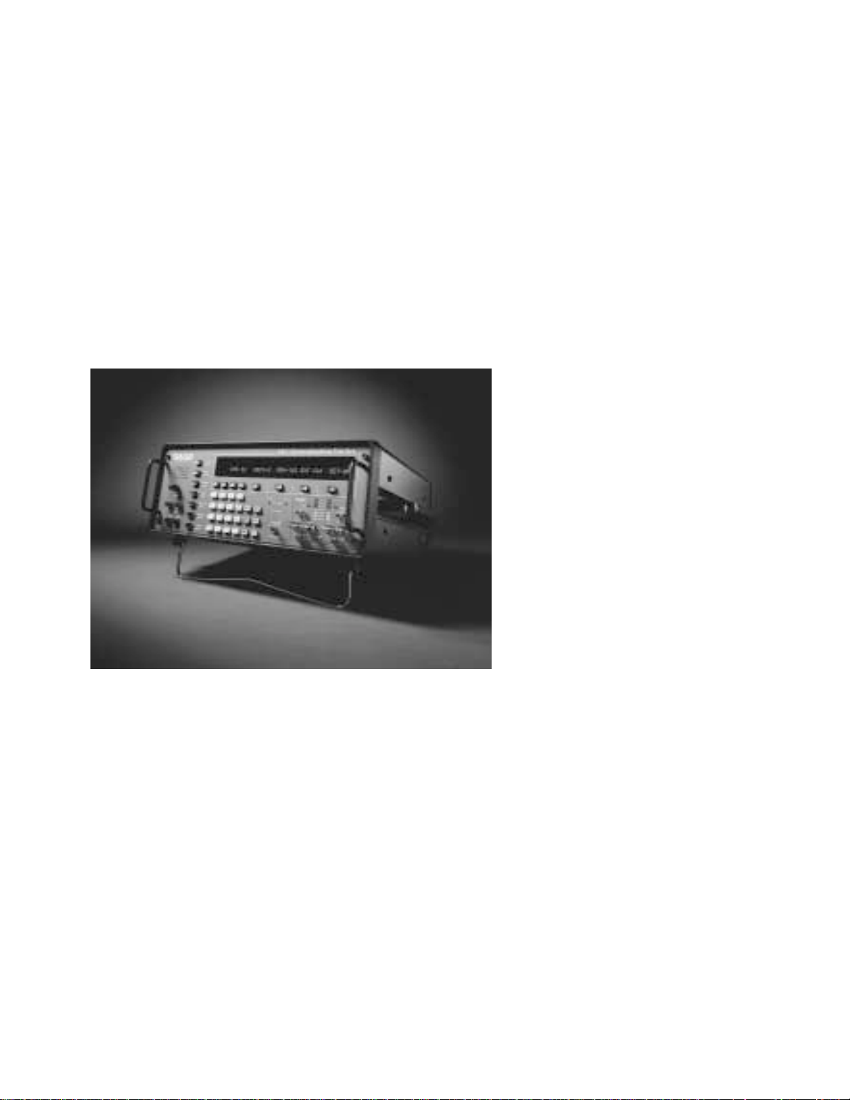
Sage Instruments 930i Communications Test Set
Table of Contents
Contents Page
SECTION I GENERAL INFORMATION .............................................................................. 1—1
1-1 INTRODUCTION ..................................................................................................... 1—1
1-1.1 Contacting Sage Instruments....................................................................... 1—1
1-2 INITIAL INSPECTION ............................................................................................. 1—2
1-3 TYPOGRAPHICAL CONVENTIONS......................................................................... 1—2
SECTION II PREPARING FOR OPERATION/POWER-UP..................................................... 2—1
2-1 AC POWER VERSION ............................................................................................. 2—1
2-2 DC POWER VERSION ............................................................................................. 2—2
2-3 SUPPLYING POWER AC/DC................................................................................... 2—2
2-4 COLD BOOTING .................................................................................................... 2—3
2-4.1 Hardware Cold-Boot...................................................................................... 2—4
2-5 VENTILATION......................................................................................................... 2—4
2-6 INTERIOR ACCESS.................................................................................................. 2—4
2-7 SERIAL NUMBER..................................................................................................... 2—5
SECTION III FRONT PANEL OPERATION .......................................................................... 3—1
3-1 SPECIAL FUNCTION KEYS...................................................................................... 3—2
3-1.1 STO Key ......................................................................................................... 3—2
3-1.2 RCL Key......................................................................................................... 3—3
3-1.3 RCL NXT Key................................................................................................. 3—3
3-1.4 ENT Key......................................................................................................... 3—3
3-1.5 CLR Key......................................................................................................... 3—3
3-1.6 HELP Key ....................................................................................................... 3—4
3-2 MAIN FUNCTION KEYS.......................................................................................... 3—4
3-2.1 Trunk Type Function Key ............................................................................. 3—4
3-2.1.1 Setup for Analogue Trunk Types .......................................................... 3—4
3-2.1.2 Setup for SF (Single Frequency) Supervision ........................................ 3—5
3-2.2 Dial/Ring Function Key ................................................................................ 3—6
3-2.2.1 Dial/Ring in Analogue Mode............................................................... 3—6
3-2.2.1.1 Storing and Recalling Phone Numbers in Dial/Ring ................... 3—7
3-2.2.2 Dial/Ring in PCM Mode ....................................................................... 3—8
3-2.2.2.1 Setting up a Call/Selecting a Protocol ......................................... 3—8
3-2.2.2.2 Setting up Protocol Parameters .................................................. 3—16
3-2.2.2.3 Making a Call ............................................................................ 3—16
3-2.2.2.4 Receiving a Call......................................................................... 3—17
3-2.3 Return Loss Function Key............................................................................ 3—17
3-2.3.1 Transhybrid Loss Measurements ........................................................ 3—18
3-2.4 Send Tone Function Key ............................................................................. 3—19
3-2.5 Measure Tone Function Key ....................................................................... 3—20
3-2.6 Measure Noise Function Key ...................................................................... 3—21
© Sage Instruments 2000
9100-2930-02 01/31/00
1

Table of Contents
Contents Page
3-3 CONFIGURATOR PANEL ...................................................................................... 3—22
3-3.1 Test Cord Connections ................................................................................ 3—22
SECTION IV PCM OPERATION.......................................................................................... 4—1
4-1 CHANNELS AND TEST DIRECTION........................................................................ 4—1
4-1.1 Test Mode ..................................................................................................... 4—2
4-1.2 Test Direction ................................................................................................ 4—2
4-1.3 Clock ............................................................................................................ 4—2
4-1.4 Setup ............................................................................................................ 4—3
SECTION V OPTION MENU NUMBERS .............................................................................. 5—1
5-1 OPTION MENU NUMBER: 1 MODIFY DIAL/RING ................................................. 5—3
5-1.1 MF, DTMF or R2 Digits ................................................................................... 5—3
5-1.1.1 Level ..................................................................................................... 5—3
5-1.1.2 Frequency............................................................................................. 5—4
5-1.1.3 Timing................................................................................................... 5—4
5-1.2 DP Digits ........................................................................................................ 5—5
5-1.2.1 % Break ................................................................................................. 5—5
5-1.2.2 Pulses Per Second ................................................................................. 5—5
5-1.2.3 Interdigit Time ...................................................................................... 5—6
5-1.3 Ring Generator.............................................................................................. 5—6
5-1.3.1 Level ..................................................................................................... 5—6
5-1.3.2 Frequency............................................................................................. 5—7
5-1.3.3 Timing................................................................................................... 5—7
5-2 OPTION MENU NUMBER: 2 SEND DIGIT SEQUENCES ........................................... 5—8
5-2.1 Sending a Call More Than 18 Digits Long .................................................. 5—11
5-3 OPTION MENU #: 3 REMOTE CONTROL .............................................................. 5—12
5-3.1 Setup ........................................................................................................... 5—12
5-3.1.1 Baud Rate ........................................................................................... 5—13
5-3.1.2 Parity................................................................................................... 5—13
5-3.1.3 Bit Number.......................................................................................... 5—14
5-3.2 Terminal Selection and Reporting ............................................................. 5—14
5-4 OPTION MENU #: 4 DIGIT RECEIVER (ANALOGUE ONLY)................................... 5—16
5-4.1 Setup ........................................................................................................... 5—16
5-4.1.1 Parameters.......................................................................................... 5—17
5-4.1.2 Sequence ............................................................................................ 5—17
5-4.2 Receive........................................................................................................ 5—19
5-4.3 Analyze ....................................................................................................... 5—20
5-4 OPTION MENU #: 4 CALL ANALYZER (PCM ONLY)............................................. 5—21
5-5 OPTION MENU #: 5 MEASURE RING VOLTAGE ................................................... 5—24
5-5.1 Setup ........................................................................................................... 5—24
5-6 OPTION MENU #: 6 DC VOLT/AMP METER......................................................... 5—25
5-6.1 Loop and Ground Start Measurements ...................................................... 5—25
5-6.1.1 Calibrate ............................................................................................. 5—25
2
© Sage Instruments 2000
9100-2930-02 01/31/00

Sage Instruments 930i Communications Test Set
Contents Page
5-6.1.2 Current................................................................................................ 5—26
5-6.1.3 Voltage ............................................................................................... 5—26
5-6.2 E&M Measurements .................................................................................... 5—27
5-7 OPTION MENU #: 7 SUPERVISION THRESHOLDS................................................ 5—28
5-7.1 Loop Supervision Thresholds Other Than 48 VDC ...................................... 5—29
5-7.2 24 VDC: E&M Supervision Thresholds ......................................................... 5—30
5-9 OPTION MENU #: 9 WINK TIMING ...................................................................... 5—32
5-10 OPTION MENU #: 10 FREQUENCY SWEEP ........................................................ 5—33
5-10.1 Setup.......................................................................................................... 5—33
5-10.1.1 Bounds .............................................................................................. 5—33
5-10.1.2 Step ................................................................................................... 5—34
5-10.1.3 Time/Level........................................................................................ 5—34
5-10.2 Sweep........................................................................................................ 5—35
5-11 OPTION MENU #: 11 IMPULSE NOISE & HITS .................................................... 5—36
5-11.1 Setup.......................................................................................................... 5—36
5-11.1.1 Noise Threshold................................................................................. 5—37
5-11.1.2 Spread............................................................................................... 5—37
5-11.1.3 Measurements Per Second ............................................................... 5—37
5-11.1.4 PH/GH Thresholds and Test Length.................................................. 5—38
5-11.2 Measure .................................................................................................... 5—38
5-12 OPTION MENU #: 12 WINK MARGINING ......................................................... 5—40
5-13 OPTION MENU #: 13 PHASE & AMPLITUDE JITTER............................................ 5—41
5-14 OPTION MENU #: 14 SET TIME AND DATE........................................................ 5—43
5-15 OPTION MENU #: 15 BEEP ON ERR? .................................................................. 5—44
5-16 OPTION MENU #: 16 DIGIT RECEIVER TIMEOUT................................................ 5—45
5-17 OPTION MENU #: 17 ENVELOPE DELAY ............................................................ 5—46
5-17.1 Setup.......................................................................................................... 5—47
5-17.1.1 Bounds .............................................................................................. 5—48
5-17.1.2 Step ................................................................................................... 5—48
5-17.1.3 Time/Level........................................................................................ 5—49
5-17.2 Send........................................................................................................... 5—50
5-17.3 Repeat ....................................................................................................... 5—52
5-18 OPTION MENU #: 18 PEAK TO AVERAGE RATIO (P/AR).................................. 5—53
5-19 OPTION MENU #: 19 4-TONE INTERMODULATION DISTORTION ....................... 5—55
5-20 OPTION MENU #: 20 30 BIT DISPLAY ................................................................. 5—57
5-21 OPTION MENU #: 21 TOGGLE A\B BITS ............................................................. 5—58
5-22 OPTION MENU #: 22 ABSOLUTE DELAY............................................................ 5—59
5-22.1 Setup and Testing (Send Unit)................................................................... 5—59
5-22.2 Setup and Testing (Repeater).................................................................... 5—60
5-25 OPTION MENU #: 25 FAR END RESPONDER ...................................................... 5—62
5-25.1 Setting the TLP and Enabling Manual Sequence..................................... 5—62
5-26 OPTION MENU #: 26 ROTL/RESPONDER............................................................ 5—65
5-26.1 Setting the TLP ........................................................................................... 5—65
5-26.2 Extended 105 Responder Tests.................................................................. 5—67
5-26.3 Test ............................................................................................................ 5—68
5-26.4 Results........................................................................................................ 5—68
© Sage Instruments 2000
9100-2930-02 01/31/00
3

Table of Contents
Contents Page
5-27 OPTION MENU #: 27 ROTL INTERROGATOR ...................................................... 5—71
5-27.1 Setup.......................................................................................................... 5—72
5-27.2 Test ............................................................................................................ 5—74
5-27.3 Results........................................................................................................ 5—75
5-29 OPTION MENU #: 29 CALL 102 LINE................................................................. 5—76
5-29.1 Setup.......................................................................................................... 5—76
5-29.2 Test ............................................................................................................ 5—77
5-29.3 Results........................................................................................................ 5—78
5-30 OPTION MENU #: 30 ADJUST TLP ...................................................................... 5—79
5-32 OPTION MENU #: 32 DIAL-UP TESTLINE............................................................. 5—80
5-33 OPTION MENU #: 33 DIAL-UP SWEEP ................................................................ 5—81
5-34 OPTION MENU #: 34 SELECT REPORTS............................................................... 5—82
5-35 OPTION MENU #: 35 DUAL TONE SENDER ........................................................ 5—83
5-35.1 Setup.......................................................................................................... 5—83
5-35.1.1 Frequency and Level ....................................................................... 5—84
5-35.1.2 Pattern .............................................................................................. 5—85
5-35.2 Preset ......................................................................................................... 5—85
5-35.3 Send........................................................................................................... 5—85
5-37 OPTION MENU #: 37 LINE STATUS ..................................................................... 5—86
5-39 OPTION MENU #: 39 REMOTE AUDIO............................................................... 5—87
5-40 OPTION MENU #: 40 SEND PCM ALARMS....................................................... 5—89
5-41 OPTION MENU #: 41 READ E1 VOLTAGE.......................................................... 5—90
5-43 OPTION MENU #: 43 E1 ERROR COUNTERS ....................................................... 5—92
5-43.1 Example: MON 1&2 Mode ........................................................................ 5—92
5-44 OPTION MENU #: 44 E1 ERROR HISTORY........................................................... 5—94
5-44.1 Example: MON 1&2 Mode ........................................................................ 5—94
5-44.2 View .......................................................................................................... 5—95
5-44.3 Print ........................................................................................................... 5—95
5-45 OPTION MENU #: 45 E1 ERROR INJECT ............................................................. 5—96
5-45.1 Error Type Selection .................................................................................. 5—96
5-45.2 Setup......................................................................................................... 5—97
5-46 OPTION MENU #: 46 E-1 BIT ERROR RATE ......................................................... 5—99
5-46.1 Testing between two EOs.......................................................................... 5—99
5-46.1.1 Customizing Parameters ................................................................. 5—101
5-46.1.2 The USER Pattern .............................................................................5—102
5-46.2 Test ......................................................................................................... 5—103
5-46.2.1 BER Testing Two E1 Spans Simultaneously..................................... 5—104
5-46.3 History...................................................................................................... 5—104
5-46.3.1 View.................................................................................................5—105
5-46.3.2 Print..................................................................................................5—105
5-55 OPTION MENU #: 55 FRACTIONAL E1 BERT.....................................................5—106
5-55.1 Setup........................................................................................................ 5—106
5-55.2 Test .......................................................................................................... 5—108
5-55.2.1 Testing Contiguous and Noncontiguous Channels.........................5—108
5-55.2.2 Testing True-Noncontiguous Channels........................................... 5—109
5-55.3 History...................................................................................................... 5—110
4
© Sage Instruments 2000
9100-2930-02 01/31/00

Sage Instruments 930i Communications Test Set
Contents Page
5-55.3.1 View.................................................................................................5—110
5-55.3.2 Print..................................................................................................5—111
5-56 OPTION MENU #: 56 64-KBIT E1 BERT.............................................................. 5—112
5-56.1 Setup........................................................................................................ 5—113
5-56.2 Test .......................................................................................................... 5—114
5-56.3 History...................................................................................................... 5—116
5-56.3.1 View.................................................................................................5—116
5-56.3.2 Print..................................................................................................5—116
5-57 OPTION MENU #: 57 DS-0 LOOPBACK............................................................. 5—117
5-57.1 Digital Loopback ..................................................................................... 5—117
5-57.2 VF Loopback ........................................................................................... 5—118
5-59 OPTION MENU #: 59 ECHO CANCELLER DISABLE........................................... 5—119
5-60 OPTION MENU #: 60 HUM FILTER.................................................................... 5—121
5-62 OPTION MENU #: 62 GROUP DELAY................................................................ 5—122
5-62.1 Setup........................................................................................................ 5—122
5-62.1.1 Bounds ............................................................................................ 5—122
5-62.1.2 Step ..................................................................................................5—123
5-62.1.3 Time/Level...................................................................................... 5—123
5-62.2 Send......................................................................................................... 5—124
5-62.3 Measure ...................................................................................................5—125
5-63 OPTION MENU #: 63 PCM ERROR HISTORY..................................................... 5—126
5-65 OPTION MENU #: 65 ATME FAR END RESPONDER.......................................... 5—127
5-66 OPTION MENU #: 66 ATME DIRECTOR ............................................................ 5—129
5-66.1 Setup........................................................................................................ 5—129
5-66.2 Test .......................................................................................................... 5—132
5-66.3 View ........................................................................................................ 5—133
5-69 OPTION MENU # 69 FAR 23 TONE RESPONDER................................................5—134
5-70 OPTION MENU #: 70 23 TONE DIRECTOR........................................................ 5—135
5-70.1 Setup........................................................................................................ 5—135
5-70.2 Test .......................................................................................................... 5—136
5-70.3 Results...................................................................................................... 5—136
5-70.3.1 Print..................................................................................................5—137
5-71 OPTION MENU #: 71 23 TONES TEST................................................................ 5—138
5-71.1 Setup........................................................................................................ 5—139
5-71.2 View ........................................................................................................ 5—139
5-75 OPTION MENU #: 75 REMOTE UPGRADE......................................................... 5—141
5-75.1 Installing Sage Software Upgrade Files on a Hard Disk ..........................5—141
5-75.2 Downloading Software to the 930i from a Computer..............................5—142
5-75.3 Downloading Software to the 930i Remotely Using a Modem .............. 5—143
5-75.3.1 Preparing the Equipment ............................................................... 5—143
5-75.3.1.1 PC Cable Connections ................................................................. 5—144
5-75.3.1.2 Modem Configurations .......................................................... 5—144
5-75.3.2 Performing a Remote Download.....................................................5—146
5-80 OPTION MENU #: 80 KEYBOARD LOCK OUT....................................................5—147
5-87 OPTION MENU #: 87 TPT BURST LENGTH......................................................... 5—148
5-89 OPTION MENU #: 89 PRINTER HAND SHAKE....................................................5—149
© Sage Instruments 2000
9100-2930-02 01/31/00
5

Table of Contents
Contents Page
5-91 OPTION MENU #: 91 SOFTWARE VERSION...................................................... 5—150
5-92 OPTION MENU #: 92 RESET 930 ........................................................................5—151
5-93 OPTION MENU #: 93 TEST DISPLAY.................................................................. 5—152
5-94 OPTION MENU #: 94 LIST OPTIONS.................................................................. 5—153
5-95 OPTION MENU #: 95 DRY CIRCUIT .................................................................. 5—154
5-97 OPTION MENU #: 97 HOLD CONTROL ............................................................. 5—155
SECTION VI REMOTE CONTROL OPERATION ...................................6—1
6-1 INTRODUCTION ..................................................................................................... 6—1
6-2 CONNECTIONS ...................................................................................................... 6—1
6.3 930I REMOTE CONTROL SETUP.............................................................................. 6—2
6-3.1 Baud Rate...................................................................................................... 6—2
6-3.2 Parity ............................................................................................................. 6—3
6-3.3 Bit Number .................................................................................................... 6—3
6-4 PRINTER MODE ...................................................................................................... 6—4
6-4.1 Supported Printer Configurations.................................................................. 6—4
6-4.2 Printer Applications....................................................................................... 6—5
6-4.3 Setting Printer Mode Parameters .................................................................. 6—5
6-4.4 Printing Test Results....................................................................................... 6—6
6-4.5 Printer Handshake ........................................................................................ 6—8
6-4.6 Print Formats ................................................................................................. 6—8
6-5 TERMINAL MODE .................................................................................................. 6—9
6-5.1 Setting Terminal Mode Parameters ............................................................ 6—10
6-5.2 Terminal Keyboard Equivalents to the 930i Keypad................................ 6—11
6-5.3 Troubleshooting .......................................................................................... 6—11
6-6 COMPUTER MODE ............................................................................................... 6—11
6-6.1 Computer Keyboard Equivalents to the 930i Keypad .............................. 6—12
6-6.2 Setting Computer Mode Parameters........................................................... 6—14
6-6.3 Input to the 930i .......................................................................................... 6—14
6-6.4 Output from the 930i ................................................................................... 6—14
6-6.5 Display Line Formats .................................................................................. 6—15
6-7 PROGRAMMERS NOTES....................................................................................... 6—16
6-7.1 Initializing the 930i ...................................................................................... 6—16
6-8 HELP MENU IN REMOTE CONTROL ..................................................................... 6—17
6-9 BELL CHARACTER................................................................................................ 6—22
SECTION VII SPECIFICATIONS...........................................................7—1
7-1 MEASUREMENT STANDARDS ................................................................................ 7—1
7-2 LEVEL/FREQUENCY MEASUREMENTS................................................................... 7—1
7-3 NOISE MEASUREMENTS......................................................................................... 7—1
7-4 3-LEVEL IMPULSE NOISE ........................................................................................ 7—2
7-5 RETURN LOSS MEASUREMENT............................................................................... 7—2
7-6 PEAK TO AVERAGE RATIO (P/AR) ........................................................................ 7—2
7-7 PHASE AND AMPLITUDE JITTER MEASUREMENTS................................................ 7—2
6
© Sage Instruments 2000
9100-2930-02 01/31/00

Sage Instruments 930i Communications Test Set
Contents Page
7-8 TRANSIENT (HITS) MEASUREMENTS ...................................................................... 7—3
7-9 ENVELOPE DELAY DISTORTION MEASUREMENTS ................................................. 7—3
7-10 GROUP DELAY DISTORTION MEASUREMENTS..................................................... 7—3
7-11 ABSOLUTE DELAY MEASUREMENTS .................................................................... 7—4
7-12 23 TONE TEST ....................................................................................................... 7—4
7-13 INTERMODULATION DISTORTION........................................................................ 7—5
7-14 SUPERVISION AND SIGNALLING ......................................................................... 7—5
7-15 E-1 PCM CHANNEL ACCESS ................................................................................ 7—6
© Sage Instruments 2000
9100-2930-02 01/31/00
7


Sage Instruments 930i Communications Test Set
SECTION I
GENERAL INFORMATION
1-1 INTRODUCTION
The Sage 930i communications test set is designed to perform voiceband tests on analogue and digital
trunks, as well as cellular test lines.
This manual is divided into seven sections: Section I provides general reference information on the
930i; Section II describes preparations for operation; Section III describes the operation of the front
panel, including the main test functions; Section IV describes the operation of the PCM functions;
Section V describes the Option Menu functions; Section VI describes remote control operation; and
Section VII lists the specifications for the 930i.
1-1.1 Contacting Sage Instruments
Information
General
To contact Sage Instruments in writing, send correspondence to:
Sage Instruments, Inc.
240 Airport Blvd.
Freedom, CA 95019-2614
or send email to:
sales@sageinst.com or support@sageinst.com
or fax inquiries to:
(831) 761-2452
To reach our Technical Support and Customer Service Departments by phone, call:
(831) 761-1000, M-F, 9 a.m. to 5 p.m., Pacific Time.
or fax our Technical Support and Customer Service Departments any time at:
(831) 761-9246
To receive company and product information via the World Wide Web, visit our home page at:
http://www.sageinst.com
Be sure to specify Model 930i when asking for technical support. Customers located outside of the U.S.
may also contact their nearest Sage distributor for assistance.
© Sage Instruments 1998
9100-2930-02 7/10/98
1-1

Section I General Information
1-2 INITIAL INSPECTION
General
Check the shipping carton for any visible signs of damage. Carefully unpack and remove the 930i from
Information
the shipping container. If the 930i is received in damaged condition, file a claim with the carrier and mail
a copy of the claim to Sage Instruments.
The following items should be included in the shipping container:
• 930i Communications Test Set.
• 930i Operating Manual.
• AC power cord. (if AC system has been purchased.)
Accessories may be shipped separately from the 930i, depending on their size. Check the shipping
invoice against the contents of the received boxes.
1-3 TYPOGRAPHICAL CONVENTIONS
In this manual, text appearing in bold COURIER typeface denotes information appearing on the 930i
display panel.
1-2
© Sage Instruments 1998
9100-2930-02 7/10/98
Sage Instruments 930i Communications Test Set
SECTION II
PREPARING FOR OPERATION/POWER-UP
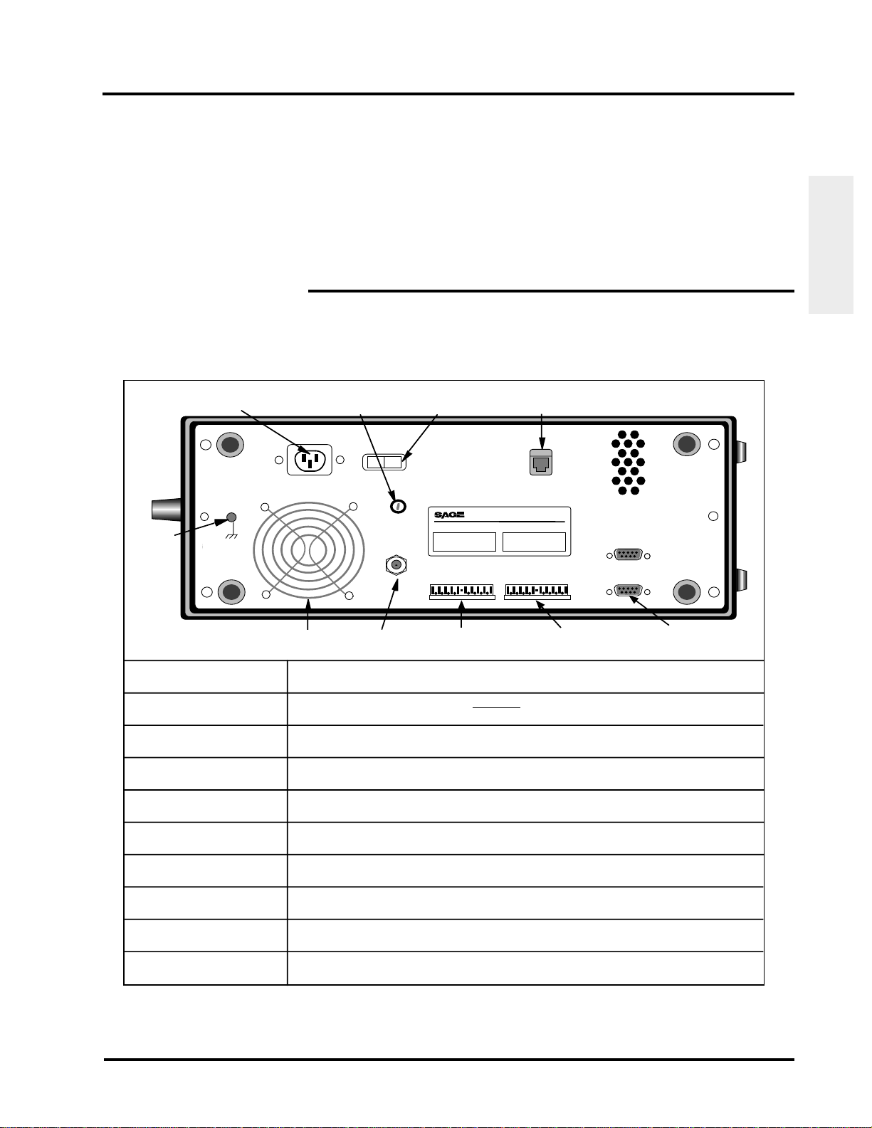
2-1 AC POWER VERSION
The table shown below describes the components of the 930i (AC power version) rear panel.
Table 2-1 Rear Panel (AC Power Supply)
AC Power (IEC-Type) Connector
The BNC jack enables the 930A to connect to an external clock source via a
coaxial cable.
Do Not Obstruct Fan Inlet
Ground
Lug
Chassis
Ground
Line In
115V AC
Fuse
Holder
ON OFF
Power Switch
Power
Fuse
5x20mm
3.15A
Ext Clk
ON/OFF
Remote Audio Jack
INSTRUMENTS
240 AIRPORT BOULEVARD FREEDOM CA 95019 U.S.A. (408) 761-1000
Model Number: 930i Serial Number: 01234
Analog
SG
SB
M
E
R1
T1
R
T
PCM
12
) In
)Out
) In
AuxAux
)Out
RS 232C
(DCE)
Preparation for
Operation
Ground Lug
Fan Inlet
RS-232C Connector
AC Power Connector
ON/OFF Power Switch
Fuse Holder
Analogue Rear Panel
Access
PCM Rear Panel
Access
Remote Audio Jack
External Clock
Fan
Inlet
External
Clock
Analogue Rear
Panel Access
PCM Rear
Panel Access
9 Pin RS-232C
(DCE)Connector
Grounds the 930i chassis.
Provides ventilation to the 930i.
Do not obscure fan inlet.(or outlet holes at the
top right).
Enables connection to Data Terminal Equipment (DTE).
Connects the 930i to a 115VAC power supply (depending on power supply type
purchased) via an IEC type connector.
Turns the 930i on and off.
Holds a 2-amp Slo-Blo fuse. Turn 1/4 turn counterclockwise to open.
Enables connection to a Jack Field from the rear panel.
Enables connection to a Jack Field from the rear panel .
Enables remote audio connection to a trunk under test via a separate dial-up line.
(Requires Purchased Option 930i-47, Remote Audio Monitor)
The BNC jack enables the 930i to connect to an external clock source via a
coaxial cable.
© Sage Instruments 2000
9100-2930-02 01/31/00
2-1
Section II Preparing For Operation/Power-Up
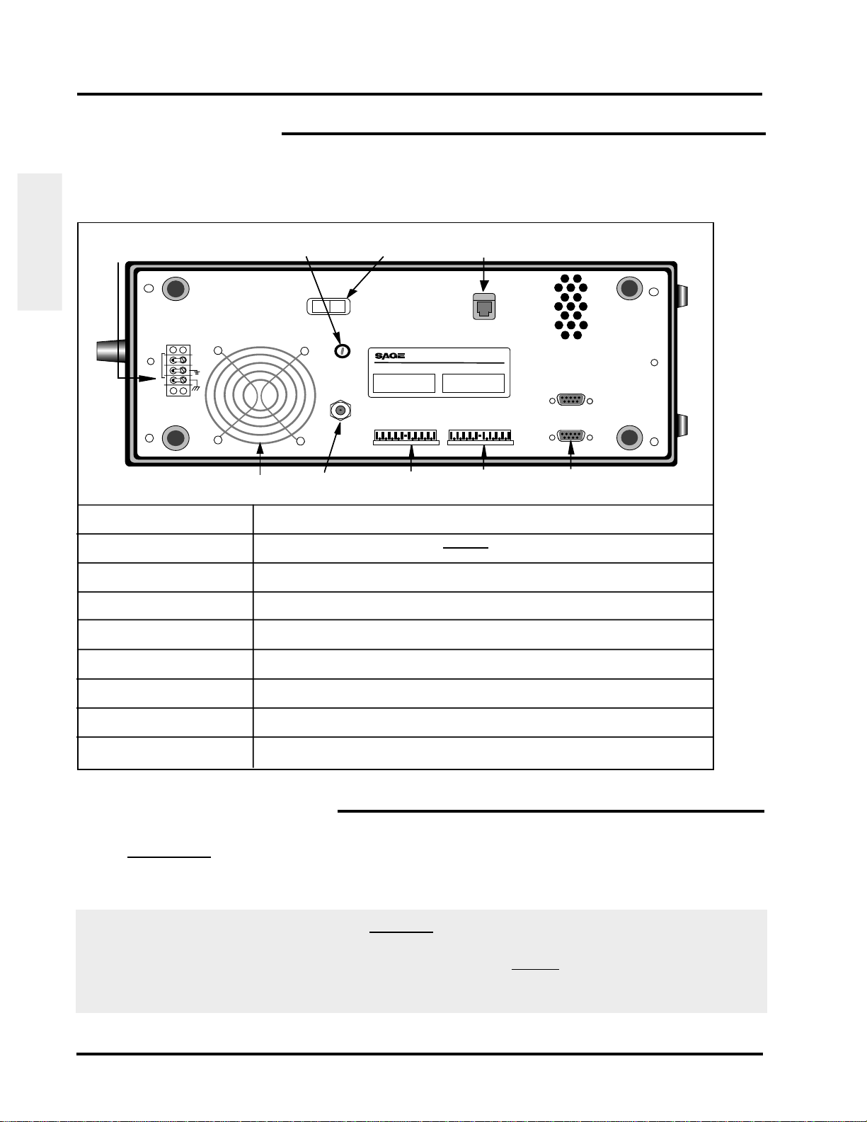
2-2 DC POWER VERSION
The table shown below describes the components of the 930i (DC power version) rear panel.
Table 2-2 Rear Panel (DC Power Supply)
ON/OFF
Barrier Terminal Block
Fuse Holder
Power Switch
Remote Audio Jack
Operation
Preparation for
Barrier Terminal Block
Fan Inlet
RS-232C Connector
ON/OFF Power Switch
Fuse Holder
Analogue
Rear Panel Access
PCM
Rear Panel Access
Remote Audio Jack
External Clock
Do Not Obstruct Fan Inlet
-48V
DC
Chas
Gnd
Fan Inlet
Power
ON OFF
INSTRUMENTS
Fuse
5x20mm
3.15A
Ext Clk
External Clock
240 AIRPORT BOULEVARD FREEDOM CA 95019 U.S.A. (408) 761-1000
Model Number: 930i Serial Number: 01234
Analog
SG
SB
M
E
R1
T1
R
T
Analog Rear
Panel Access
PCM
12
)Out
) In
PCM Rear
Panel Access
Aux
Aux
)Out
) In
RS 232C
(DCE)
9 Pin RS-232C
(DCE)Connector
Connects 930i to a -48V DC power supply
Provides ventilation to the 930i.
Do not obscure fan inlet
(or outlet holes at the top right).
Enables connection to Data Terminal Equipment (DTE).
Turns the 930i on and off.
Holds a 2-amp Slo-Blo fuse. Turn 1/4 turn counterclockwise to open.
Enables connection to a Jack Field from the rear panel.
Enables connection to a Jack Field from the rear panel.
Enables remote audio connection to a trunk under test via a separate dial-up line.
The BNC jack enables the 930i to connect to an external clock source via a
coaxial cable.
2-3 SUPPLYING POWER AC/DC
1. AC version (if your back panel looks like the one on the previous page)
Connect the 930i to a 115/220 V AC power source via a 3-prong power cord. The power
connector is located next to the red ON/OFF rocker switch at the rear of the 930i.
Warning! If the rear panel of your AC unit does not look like the one on the previous page, you could
seriously damage your unit if you do not connect it to the proper power source. Older units,
which have a different rear panel and power supply, do not automatically switch between
115 V AC and 220 V AC operation but are equipped to operate only at a single voltage. You
must check your unit's power requirements before plugging it in and turning it on.
2-2
© Sage Instruments 2000
9100-2930-02 01/31/00
Sage Instruments 930i Communications Test Set
In addition, older units have a different rear panel configuration. If you are unsure of your unit's
power requirements, contact the Sage Customer Service Department for assistance.
DC version
Connect the 930i to a -48 V DC power source via 16 gauge wire. The wires connect at the two
phillips head screws on the barrier terminal block.
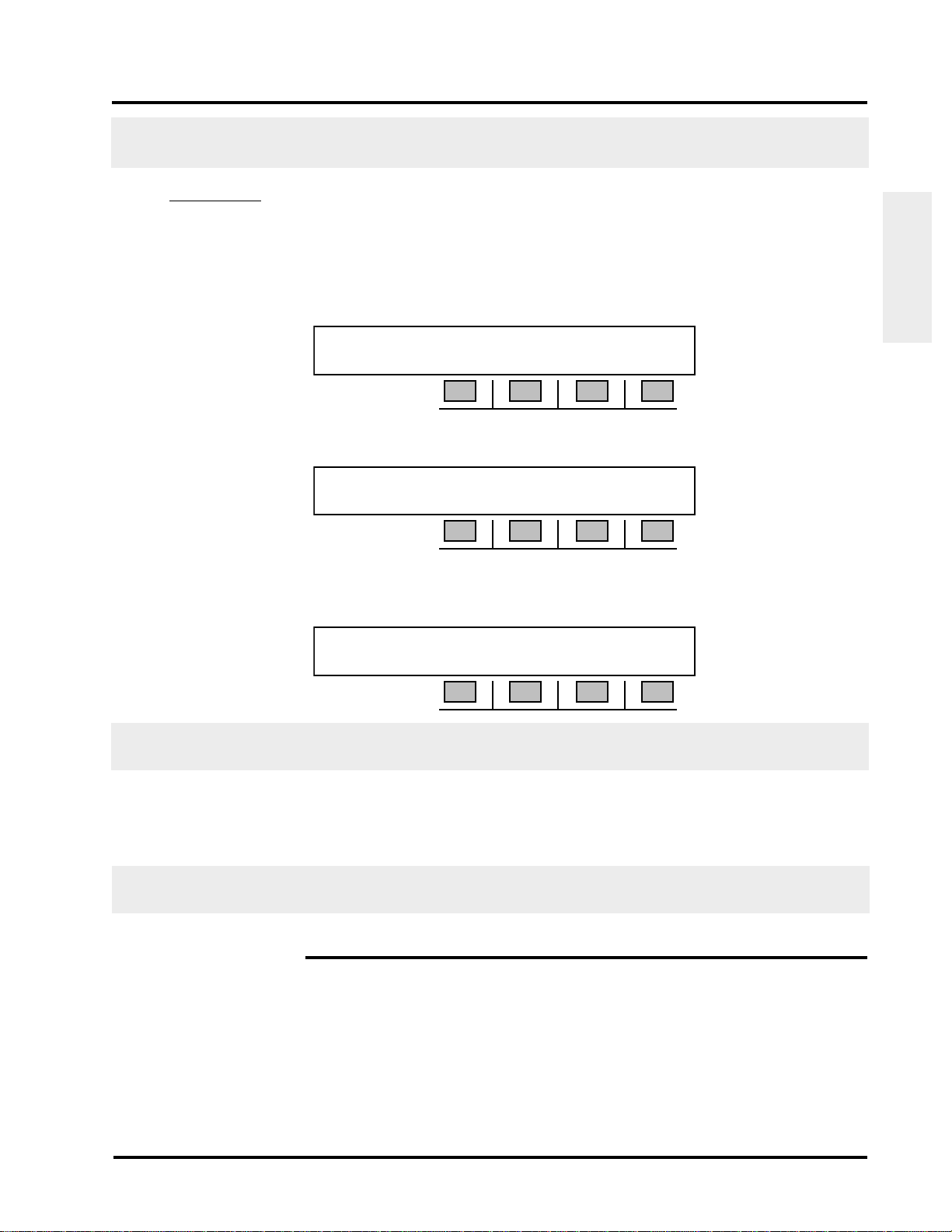
2. Toggle the red ON/OFF rocker switch at the rear of the 930i to ON. The 930i will run through
a ram test:
RAM TEST...
K1 K2 K3 K4
After a moment the display will change to read:
SAGE INSTRUMENTS 930 MEMORY TEST
K1 K2 K3 K4
If the memory check is successful the message: MEMORY TEST will change to MEMORY OK! If
the memory test is successful, the display will change to read:
Preparation for
Operation
SAGE INSTRUMENTS 930i ver. N.NN
K1 K2 K3 K4
N.NN is the version of software installed in the unit. Note the status of the LEDs on the front panel. If
an error has been detected, all of the LEDs will be lit. Turn the 930i off and perform a cold boot.
After a brief pause, the 930i will then advance to the last Trunk Type setup displayed when the
unit was last powered-up.
To ensure optimal performance, do not store the 930i adjacent to other equipment that produced a lot
of heat, dust, static, ozone, sparks, or strong magnetic fields.
2-4 COLD BOOTING
You can perform either a hardware or a software cold boot. A hardware cold boot clears all memory
registers and resets the 930i to its default parameters. A software cold boot retains all serial I/O
settings but resets everything else to the factory default parameters. The procedure for performing a
hardware cold boot is described below.
© Sage Instruments 2000
9100-2930-02 01/31/00
2-3
Section II Preparing For Operation/Power-Up
The software cold-boot function has been added for the convenience of persons writing remote control
software, and can be performed by using OPTION MENU #: 92 RESET 930. (Refer to Section 5-92,
OPTION MENU #: 92 RESET 930 for a complete description of this function) This function also
describes the procedure for performing a warm boot from the Option Menu, which is the equivalent
of turning the 930i off and on.
2-4.1 Hardware Cold-Boot
Operation
To perform a hardware cold-boot:
Preparation for
1. Turn the 930i off.
2. Hold down the Trunk Type function key located on the left side of the front panel.
3. Turn the 930i on. Do not release the Trunk Type function key until the display has scrolled all
the way across the screen. The display reads:
NORMAL LOOP BRIDGE CONTACT 2W 900
K1 K2 K3 K4
A successful cold boot will return the 930i to its default settings and erase all stored items.
2-5 VENTILATION
The 930i is cooled by air drawn into the fan inlet on the lower left-hand side of the rear panel and expelled
through the ventilation holes at the top right-hand corner.
To insure proper ventilation:
1. Check that the vents are not obstructed during operation.
2. Do not place the 930i rear-panel-down on thick carpeting during operation.
3. Make sure that the operating environment is free of dust.
4. Inspect the vents periodically for dust buildup.
2-6 INTERIOR ACCESS
Access to the interior of the 930i is obtained by removing the four phillips head screws (two on each side
of the unit) that hold the top cover in place, and then lifting off the top panel. DO NOT attempt to gain
access by removing the rear panel.
Since the 930i contains no user serviceable parts, interior access is not normally necessary unless you
are performing a factory authorized field upgrade.
2-4
© Sage Instruments 2000
9100-2930-02 01/31/00

2-7 SERIAL NUMBER
Sage Instruments 930i Communications Test Set
The product serial and model numbers are located on a serial tag on the rear panel.
Preparation for
Operation
© Sage Instruments 2000
9100-2930-02 01/31/00
2-5

Sage Instruments 930i Communications Test Set
SECTION III
FRONT PANEL OPERATION
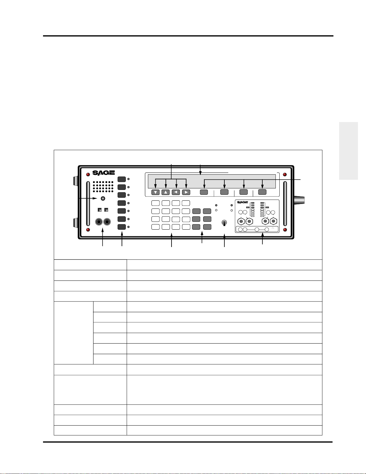
This section provides information regarding operation of the front panel keys, configurator panels,
switches and test cord connections. The table below provides an overview of each of the front panel
functions.
Table 3-1 Front Panel Configuration
Front Panel
Operation
Speaker and
Volume
Control
Speaker and
Volume Control
Telset
Jacks
Function
Keys
Numeric
Keypad
Special
Function
Keys
Hookswitch and
Supervision LEDs
Test Cords and
Front Panel Jacks
Configurator Panels
Soft Keys
Arrow Keys
INSTRUMENTS
Volume
TelSet
Telset
Jacks
Function
STO
Key
RCL
Key
RCL NXT
Key
ENT
Key
CLR
Key
HELP
Key
Keys
Trunk
Type
Dial/
Ring
Return
Loss
Send
Tone
Measure
Tone
Measure
Noise
Option
Menu
Arrow
Keys
1 2
4
7
KP
*
3
6
5
8
9
FE
#
0
ST
Numeric
Keypad
STP
ST2P
ST3P
Display
Screen
K1 K2 K3 K4
Special
Keys
Orig Term
RCL
CLR
HELP
Hookswitch and
Supervision LEDs
Off Hook
On Hook
Off Hook
On Hook
A
B
STO
RCL
C
NXT
D
ENT
+/-
Function
930i Communications Test Set
No Sig
INSTRUMENTS
12
No AIS
No FAS
History History
Alarms
12
120
Ω
MFAS
HDB3
Rx Rx TxTx
CRC4
75Ω 75Ω
PCM
Analog
T1R1 TR SB/SG E/M
E-1 Configurator Panel
with Test Cords and
Front Panel Jacks
120
Ω
!
CAUTION
-48VDC
Controls speaker volume.
Allows for an external telephone monitor. The "cufflinks" are for use with a telephone lineman's test set
(external butt-in set) 48 V battery is supplied in Dial/Ring. The telset is 4-wire.
The 7 black keys control the main test functions of the 930i. (see Section 3-7 for a description of each function)
The 16 white keys operate like a telephone keypad. They allow you to enter numerical data. Any leading
blanks are treated as zeroes. The sign of a number can be changed by pressing the D+/- key.
Allows you to store data that has been input using the softkeys or numeric keypad. (see Section 3-6.1)
Allows you to recall a test setup or other parameters that have been stored in memory. (see Section 3-6.2)
Advances to the storage location following the last location recalled. (see Section 3-6.3)
Allows you to enter information once numeric data has been selected. (see Section 3-6.4)
Clears or initializes sequences allowing new entries to be made. DOES NOT clear to zero. (see Section 3-6.5)
Displays a series of screens leading you step-by-step through the function selected. (see Section 3-6.6)
The chrome switch allows you to toggle on/off hook.The LEDs show the status at the originate (ORIG) and
terminate (TERM) ends.
The jacks are used with the following configurations:
TR -used on 2-wire loop start, ground start, or reverse battery trunks
TR&T1R1-used on 4 wire trunks
E/M-used on E&M types I-V
SB/SG-used on signal battery/signal ground leads for E&M type II-IV
PCM IN 1/PCM OUT 1-used on single direction EI carrier circuits
PCM IN 2/PCM OUT 2-used in dual direction monitor or drop and insert
Contains optional interface jacks and/or LED status lights depending on whether analog or PCM functions
have been purchased. (see Section 3-8)
The four keys labelled K1-K4 allow you to select from menu items that appear above each key on the display
panel.
Allow you to scroll through items listed on the display panel.
Soft
Keys
© Sage Instruments 2000
9100-2930-02 01/31/00
3-1

Section III Front Panel Operation
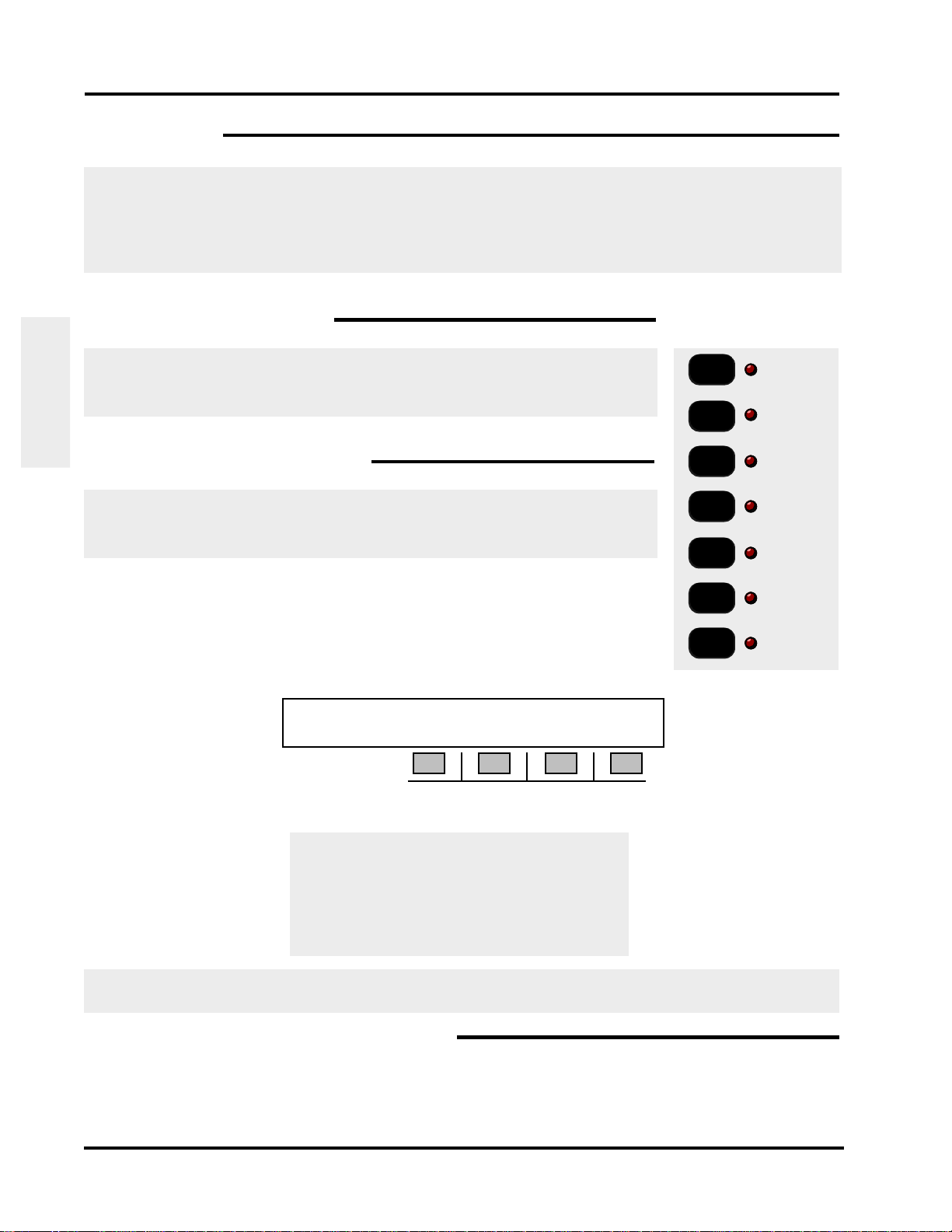
3-1 SPECIAL FUNCTION KEYS
The Special Function keys are the six light gray keys located to the right
of the numeric keypad.
STO
RCL
RCL
3-1.1 STO Key
NXT
ENT
The STO key is used to store a particular test setup, outpulse sequence, digit
string, or any Option Menu setup. Note that this function does not store
current measurement results.
To store a setup:
Operation
Front Panel
1. Press the STO key. The display reads:
STORE TEST# NNN [999 TO ESC]
Special
Function
Keys
K1 K2 K3 K4
2. Use the numeric keypad to enter the number corresponding to the register location desired.
NNN in the display above is the number of the storage location. This may be any number between
1 and 998.
3. Press the ENT key. The 930i automatically increments the storage location after each entry.
The 930i will retain what has been stored in its memory until the lithium battery on its CPU runs down,
you overwrite that memory location, or you perform a cold-boot.
CLR
HELP
Storing something new in a memory location automatically replaces the previous contents. A general
description of the stored parameters for various test situations follows:
In Trunk Type: All of the Trunk Type parameters are saved exactly as they appear on the display.
In Dial/Ring: The digit records and the protocol setup.
In Return Loss: All of the displayed parameters, including signal type, echo-suppress tone, and
transhybrid loss are saved.
In Send Tone: The level, frequency, and Tone On/Tone Off are saved.
In Measure Tone: The relative zero level is saved.
In Measure Noise: The filter type, NTG or BAL setting, and relative zero are saved.
In Option Menu: Use the STO key to save all parameters specified within that option.
3-2
© Sage Instruments 2000
9100-2930-02 01/31/00
Sage Instruments 930i Communications Test Set
3-1.2 RCL Key
To recall a test setup or other parameters which have been stored in a particular register:
1. Press the RCL key. The display reads:
RECALL TEST# NNN [999 TO ESC]
K1 K2 K3 K4
2. Use the numeric keypad to input the storage location number (between 0 and 998) of the
desired test setup.
3. Press ENT or any softkey (K1-K4) to recall the setup stored in that location.
3-1.3 RCL NXT Key
To display the setup in the storage location following the currently displayed location:
Front Panel
Operation
1. Hold down the RCL NXT key. While you hold the key, the register location is displayed.
2. Release the key to display the stored information.
Each time RCL NXT is selected, the storage location increments by one. If a storage location has no
information, the display reads: LOCATION [NN] IS EMPTY.
3-1.4 ENT Key
To accept data entered into the 930i:
1. Enter the data using the numeric keypad OR make a selection from the display using the
softkeys. Your entry options will vary depending on the function.
2. Press the ENT key. In some cases, you cannot advance to the next operation until you have
completed your data entry and pressed the ENT key.
If the 930i is in PRINTER Remote mode or COMPUTER Remote mode with the proper connections to a
printer, pressing ENT will print out the current display with the time and date stamp.
3-1.5 CLR Key
The CLR key is used to clear or initialize sequences and allow new entries to be made. It is not used
to clear a numeric value to zero. This is done by entering a zero. Press the CLR key to clear sequences
of variable length, and to clear the history LED on the E1 configurator.
© Sage Instruments 2000
9100-2930-02 01/31/00
3-3
Section III Front Panel Operation
e
e
e
3-1.6 HELP Key
Pressing the HELP key allows you to view and set each step in a procedure separately and
systematically. Selecting a parameter is done by pressing the softkey (K1-K4) directly under the
desired value appearing in the display. A cursor will appear above your selection.
Note: HELP is not available for all menus. It is most useful in navigating the remote control option.
3-2 MAIN FUNCTION KEYS
This section provides information on the operation of each function key, located
on the left of the front panel. (For information on the Option Menu function key,
refer to Section 5, Option Menu Numbers.)
Operation
Front Panel
3-2.1 Trunk Type Function Key
The Trunk Type function key is used to select and set up a trunk type. This
procedure should be done before accessing any other function, and before
performing any test or measurement.
To select a trunk type:
1. Press the Trunk Type function key. When power is first applied to the
930i it will default to the last-used configuration. The factory default
display is shown below:
NORMAL LOOP BRIDGE CONTACT 2W 900
K1 K2 K3 K4
2. Use the Up/Down Arrow keys or K1 to scroll through the available trunk types:
Trunk
Type
Make/R
Call
Return
Loss
Send
Tone
Measur
Tone
Measur
Noise
Option
Menu
Main
Function
Keys
NORMAL LOOP
REVERSE LOOP
NORMAL GND-ST
REVERSE GND-ST
E&M (Types) I-V
(OPTIONAL TYPES) PCM SF WIDEBAND
For information on using the PCM trunk type , refer to Section 4, PCM Operation. SF and Wideband
are not currently available.
3-2.1.1 Setup for Analogue Trunk Types
To set up an analogue trunk type:
1. Press K4 to select 2W 135-1200 Ohm or 4W 135-1200 Ohm impedance.
3-4
© Sage Instruments 2000
9100-2930-02 01/31/00

Sage Instruments 930i Communications Test Set
Note: If
Purchased Option 930i-70, Complex Impedance
is installed in your unit, additional
impedance types will be available under 2W trunk type. Complex impedance is identified by its
nominal impedance at 1000Hz, and replaces the standard 135 Ohms impedance. Since there
is a different value complex termination for every country, a hardware modification ismade to the
unit in production. (Currently, only the Russian and BABT complex impedances are available.
Return Loss measurements can be made on a 2W circuit when a complex impedance has been
selected. (The return loss function is not available with standard impedance types.) Refer to
Section 3-2.3 For more information on performing 2W return loss measurements.
2. Press K3 to toggle between BATTERY or CONTACT if you selected a LOOP or GND-ST trunk type,
OR between SEND-E or SEND-M if you selected an E&M trunk type. In 4W, this affects the TLP
settings. Refer to Section 5-30, OPTION MENU # 30 SET TLP.
3. Press K2 to toggle between BRIDGE or TERM (terminate) mode.
Changing trunk types or from 2W to 4W operation automatically places the 930i in BRIDGE mode. In
this mode, the 930i does not send anything. The supervision lamp marked Orig shows the end of the
circuit which the 930i would emulate if it were in TERM mode.
3-2.1.2 Setup for SF (Single Frequency) Supervision
Front Panel
Operation
SF is inherently a 4-wire trunk type and is now mainly used on special service trunks in the U.S. It has
been largely displaced in the network by digital
CCIS and SS-7 signalling types.
To setup SF supervision:
1. Press the Trunk Type function key.
2. Press K1 or use the Up/Down Arrow keys to scroll to the OPTIONAL TYPES display.
3. Press K3 under SF to enter the SF SUPERVISION trunk type.
SF SUPERVISION SEND T1R1 TERM 4W 600
K1 K2 K3 K4
4. Press K2 allows you to send on Tip/Ring (SEND TR) or Tip1/Ring1 (SEND T1R1).
5. Press K4 to select the impedance (2W 135-1200 Ohm or 4W 135-1200 Ohm). The 930i
presently does not support 2-wire SF systems which use 2 tones (2404 and 2604 Hz, for
example), nor can it be used to provide SF SUPERVISION in PCM.
6. Press K3 to toggle between BRIDGE and TERM operation.
7. Place the front panel hookswitch in the Off Hook position.
© Sage Instruments 2000
9100-2930-02 01/31/00
3-5
Section III Front Panel Operation
3-2.2 Dial/Ring Function Key
The Dial/Ring function can be used tor make and receive calls if you are in a teminate mode. In monitor
mode, it allows you to non-intrusively monitor calls.
All calls can be analyzed under Option Menu #4 Digit Receiver (Analogue Only) or Option Menu #4
Call Analyzer(PCM Only).
To make/ receive a call, or to monitor a phone line:
1. Connect the 930i to the trunk on which you will make the call, or the line to be monitored.
2. Connect the lineman’s butt in set to the TelSet jacks on the 930i front panel.
Operation
Front Panel
3. Set up a trunk under the Trunk Type function key. Refer to Section 3-2.1.
4. Place the front panel hookswitch in the On Hook position.
5. Press the Dial/Ring function key. The next display will differ depending on whether you selected
an Analogue or PCM trunk type under the Trunk Type function key. If you are in Analogue,
proceed to Section 3-2.2.1. If you are in PCM, go to Section 3-2.2.2.
3-2.2.1 Dial/Ring in Analogue Mode
In Analogue mode, a display similar to the following appears when you press the Dial/Ring function
key:
RPT? MF TR
K1 K2 K3 K4
1. Use the numeric keypad to enter the digits to be dialed. The Left Arrow key is used to insert
a one second pause into a digit sequence and appears on the display as a “-” between digits.
2. Press K3 repeatedly to scroll through the outpulsing modes. The available modes are:
3-6
• MF (multi-frequency).*
• DTMF (dual tone multifrequency).†
• DP (dial pulse). This mode is valid only in CONTACT mode or PCM; it is not available when
simulating a Central Office (supplying battery).
• RING This mode is valid only when supplying BATTERY or in PCM ring types.
• R2 This mode is available only if you selected R2 under PCM in the Trunk Type function.
© Sage Instruments 2000
9100-2930-02 01/31/00
Sage Instruments 930i Communications Test Set
3
6
9
#
1633 Hz
A
STP
B
ST2P
C
ST3P
D
697 Hz
770Hz
852 Hz
941 Hz
1100 Hz
1
1100 Hz
2
3
1300 Hz
4
5
6
1500 Hz
7
8
9
0
1700 Hz
ST3P
STP
KP
ST2P
ST
700 Hz
900Hz
1100 Hz
1300 Hz
1500 Hz
1209 Hz
1
GHI
4
PRS
7
*
1336 Hz
ABC
2
JKL
5
TUV
8
Oper
0
1477 Hz
DEF
MNO
WXY
†DTMF Tone Pairs *MF tone pairs
Changing the mode clears all digit sequences and resets all parameters to their default values.
3. Toggle the hookswitch to the Off Hook position. If you go off-hook before entering the digits
to be dialed, the digits are outpulsed as you dial.
4. Press K2 under RPT? to have the 930i send the digits. The display changes to: RPT!
When sending MF digits, first enter a KP (key pulse), enter the numbers, and end with an ST (stop pulse).
For example, an MF digit string could be KP004155551212ST.
5. Press K1 under MANUAL to send if you are in RING mode. Ringing will continue as long as you
press the button.
Front Panel
Operation
K4 is inactive. Here, the 930i indicates which leads are used for outpulsing:
(TR, T1R1, SEND-E, SEND-M, SEND AB, PCM 1 or PCM 2).
6. Use the CLR key to clear the display.
3-2.2.1.1 Storing and Recalling Phone Numbers in Dial/Ring
To store frequently used phone numbers for future recall and outpulsing, you must press the STO key
to save the currently displayed digit sequence, its outpulsing mode (MF, DTMF, DP), and any
modifications which may have been made. The parameters may be stored in any of the 998 register
locations (numbered from 1 to 998). Refer to Section 5-2, OPTION MENU #: 2 SEND DIGIT
SEQUENCES.
for example:
To store a digit sequence in register location 17:
1. Press the Dial Ring function key.
2. Use the numeric keypad to input a dial sequence (e.g., 14087611000). The display reads:
© Sage Instruments 2000
9100-2930-02 01/31/00
14087611000 RPT? DTMF TR
K1 K2 K3 K4
3-7
Section III Front Panel Operation
3. Press the STO key.
4. Select 17 using the numeric keypad and press ENT.
To recall the digit sequence:
1. Press the RCL key.
2. Select 17 using the numeric keypad and press ENT.
For IDDD applications in which a CCITT No. 5 MF sequence is being outpulsed, the required KP2 pulse
is equivalent to the ST2P pulse located on the B ST2P key on the numeric keypad. Such an IDDD MF
sequence would appear as ST2P11071738945ST.
3-2.2.2 Dial/Ring in PCM Mode
Operation
Front Panel
In PCM mode, the following display appears when you press the Dial/Ring function key:
DTMF SETUP START
K1 K2 K3 K4
1. Press K2 under DTMF to select your digit type. The display reads:
TABLE: DTMF DP MF MORE
K1 K2 K3 K4
2. Press K1 to select MF digits, K2 for DTMF digits, or K3 for R2 FORWARD digits. By pressing K4
under more, you will advance to another display where you can select between R2 BACKWARD
digits or DP digits. After making your selection, you will return to the dialling display.
3. Use the Numeric Keypad to enter your dialling digits.
Note: Although you can press K4 under START after entering the digits to be dialed and immediately
start sending and receiving digits, you should first select and set up a protocol and set up a span
by pressing K3 under SETUP. If you will be monitoring a call, you will only be required to select
and set up a protocol.
3-2.2.2.1 Setting up a Call/Selecting a Protocol
The 930i user interface has been designed to allow customers to download their own protocols to the
930i, as well as use the pre-installed protocols.
3-8
© Sage Instruments 2000
9100-2930-02 01/31/00

Sage Instruments 930i Communications Test Set
A protocol is an algorithm or set of cooperating algorithms capable of making, receiving, or monitoring
the setup of a telephone call on a particular type of telephone trunk connected to the 930i. The 930i has
been shipped with a limited number of pre-installed protocols which can be selected and set up under
the Dial/Ring function key. (Refer to Section 3-2.1.)
In addition to these pre-installed protocols, custom-designed protocols can be added for almost any
conceivable combination or permutation of protocol requirements. This flexability is indispensable in a
global market where telephone systems and protocols differ from country to country or even from region
to region within a country.
From the 930i user’s standpoint, the unit is easy to use, where calls are made or monitored through the
Dial/Ring function key and protocols are selected and set up from there using the setup menu.
Before making or receiving a call:
1. Press the K3 under SETUP from the main display. The new display reads:
SELECT: PROTOCOL PARAMS SPAN START
K1 K2 K3 K4
2. Press K1 under PROTOCOL. The display will look similar to the following:
SELECT: POTS R2Simpl R2ITU MORE
K1 K2 K3 K4
The 930i is shipped with several pre-installed protocols:
POTS
Front Panel
Operation
POTS Allows you to make a standard call on a POTS trunk. MF, DTMF and DP digits can be selected.
Parameter Default Description
N DIGITS 0 The 930i will automatically answer after N Digits have
been received. If N=0, the user must go off hook to manually answer or wait for the Digit Timout.
DIGIT TIMOUT 5000 ms If N Digits have not been received, the unit will answer
after this amount of time has elapsed.
HANGUP DELAY 1000 ms When the unit at the user end hangs up, the near end will
wait for this amount of time before going on hook.
ABORT TIME 100 ms After a call has fbeen aborted by going on hook, the unit
will wait this amount of time before sending an on hook
signal.
© Sage Instruments 2000
9100-2930-02 01/31/00
3-9

Section III Front Panel Operation
POTS (cont...)
Parameter Default Description
MIN SEIZURE 100 ms Any seizure signal that has a shorter duration than this will
be ignored.
MIN ANSWER 100 ms Any answer signal that has a shorter duration than this will
be ignored.
MIN CLEAR 100 ms Any clear signal that has a shorter duration than this will be
ignored.
MAX CLEAR 500 ms The maximum amount of time that the unit will wait before
Operation
Front Panel
clearing a call.
3-10
© Sage Instruments 2000
9100-2930-02 01/31/00

Sage Instruments 930i Communications Test Set
R2 Simple
R2 Simple allows you to make an R2 call using generic setup parameters (e.g., tail, and script).
Parameter Default Description
TAIL 2 Additional digits appended to the end of the forward digits.
(i.e., origin request)
BACK DIGITS 11131 Backward digits that tell the forward end which type of for-
ward digits to send.
N DIGITS 0 The number of destination digits that will be expected at the
answering end before pausing and then sending a pulsed
backward digit (if applicable)
DIGIT TIMOUT 5000 ms If N Digits have not been received, the unit will answer after
this amount of time has elapsed.
PULSE DELAY 3000 ms The delay between the receipt of the last forward digit at the
answering end and the time that the answering end sends a
pulsed backwards digit.
PULSE DURATION 150 ms The length of the pulsed backward digit sent from the an-
swering end.
SZ ACK DELAY 100 ms After the line is seized, thebackward end waits for this amount
of time before sending a Seizure Acknowledgement.
ANSWER DELAY 1000 ms After the last digit was received, the backward unit will wait
this amount of time before answering.
Front Panel
Operation
HANGUP DELAY 1000 ms When the unit at the other end hangs up, the near end will
wait this amount of time before going on hook.
ABORT TIME 100 ms After a call fails, the unit will wait this amount of time before
aborting.
MIN SEIZURE 100 ms Any seizure signal that has a shorter duration than this will
be ignored.
MIN ACKNOWLEDGE 100 ms Any seizure acknowledgement signal that has a shorter du-
ration than this will be ignored.
MIN ANSWER 100 ms Any answer signal that has a shorter duration than this will
be ignored.
© Sage Instruments 2000
9100-2930-02 01/31/00
3-11

Section III Front Panel Operation
R2 Simple (cont...)
Parameter Default Description
MIN CLEARFORWARD 100 ms At the forward end, any clear signal that has a shorter dura-
tion than this will be ignored.
MAX CLEARFORWARD 3000 ms After call completion, this is the maximum amount of time
the forward end unit will wait before clearing.
MIN CLEARBACKWARD 100 ms At the backward end, any clear signal that has a shorter du-
ration than this will be ignored.
Operation
Front Panel
MIN IDLE 100 ms After call completion, this is the minimum amount of time
that the unit will remain idle before it can initiate or receive
calls.
MIN BLOCK 500 ms The interval during which the line will be blocked to incoming
calls.
3-12
© Sage Instruments 2000
9100-2930-02 01/31/00
 Loading...