

Saga saga1-l4, saga1-l6, saga1-l8, saga1-l6b, saga1-l8b Installation & Operation Manual
INSTALLATION &
OPERATION
MANUAL
SAGA1-L Series
1
PREFACE
This installation & operation manual is intended as an
instruction manual for trained person who is in charge
of installation, maintenance, repair, etc.
Before installation please read the user’s guide and this
installation & operation manual carefully.

SAGA1-L Series
2
The main contents of this manual are organized into the following chapters.
Table of Contents
PREFACE
1.0
Wire Diagram of SAGA1-L series………………………………………….....p.4
2.0 Transmitter PCB Layout………………………………………………………..p.5
3.0 Receiver PCB Layout…………………………………………………………..P.6
3-1 Relay Board for SAGA1-L8, L6, L4, L8B, L6B
3-2 Independent COM Line
3-3 Receiver/Decoder Board for SAGA1-L8, L6, L4, L8B, L6B
4.0 Change of Frequency…………………………………………………………P.10
5.0 Change of NO/NC Contact of R0/START Relay..…………………………P.14
6.0 ID-Code Remote Setting ………………………………………………………P.15
7.0 Troubleshooting………………………………………………………………….P.16
Appendix
SAGA1-L Series Software Installation And Operation Instruction…………P.17~23
SAGA1-L Series
3
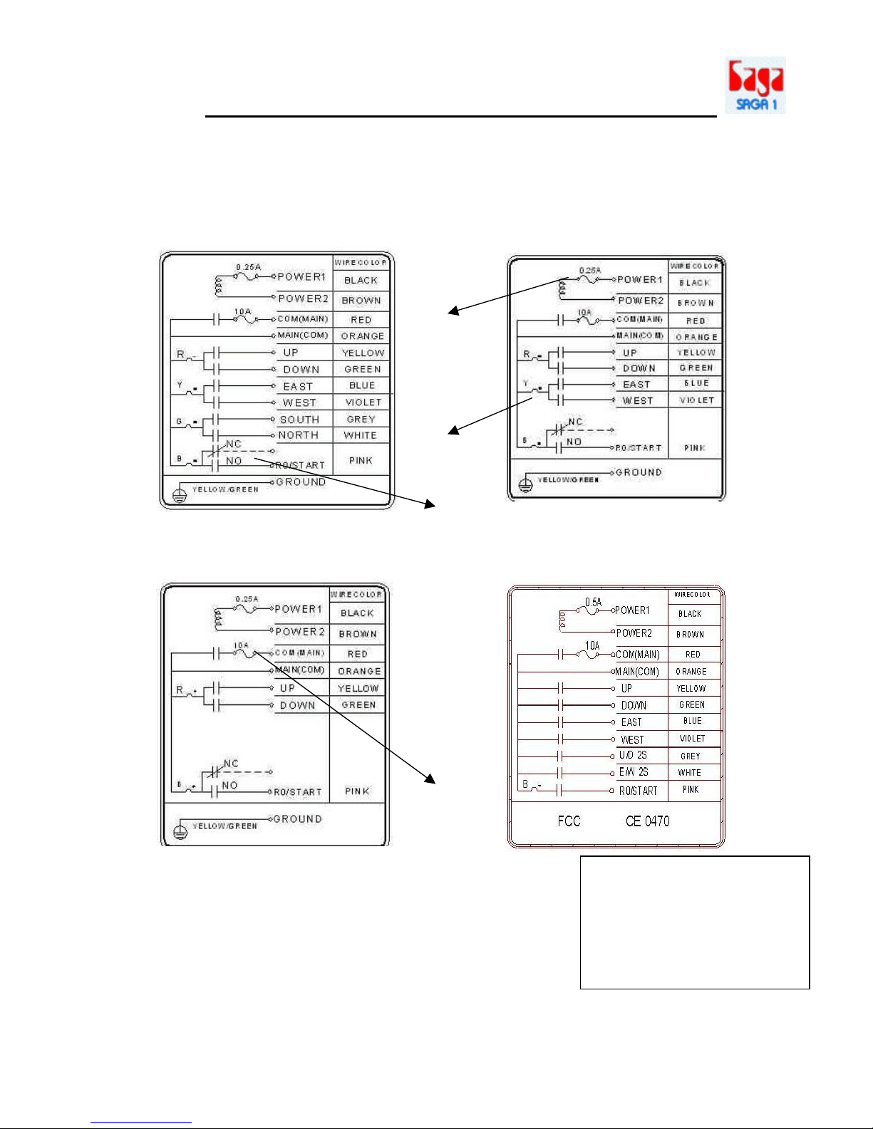
1.0
WIRE DIAGRAM OF SAGA1-L SERIES:
Remark: (1) The R0/START could be N.C. or N.O.
(2) The fuse for the power AC24/48/110/220/380V is 0.5A.
The fuse for the power DC12/24V is 1.5A.
(3) The fuse for AC type at the COM(MAIN) is 10A.
The fuse for DC type at the COM(MAIN) is 20A.
(4) The com lines have been arranged prior to shipment, if an independent
COM line is required, please refer to page:8/23.
SAGA1-L8, L8B
SAGA1-L6
SAGA1-L4
(1)
(2)
(3)
Note: The polarity directio
n for
the power of DC12/24V
isn’t required when
plugging in the power
line connector.
(4)
SAGA1-L6B
SAGA1-L Series
4
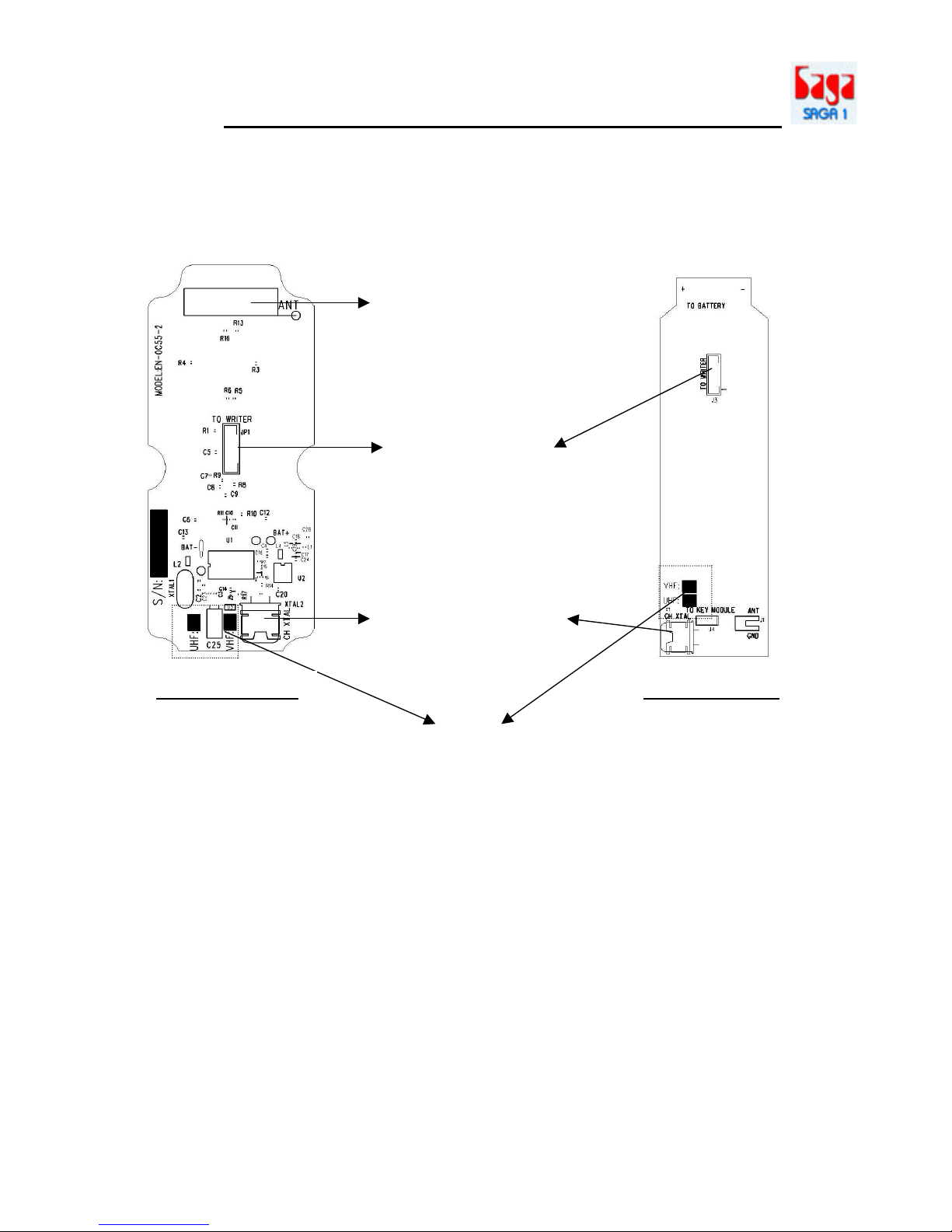
2.0
TRANSMITTER PCB LAYOUT:
This terminal is used
for copier to read
and write data or
connecting to PC for
function setting
through software.
Replacing this
Crystal to change the
frequency on the
transmitter.
There are two kinds of frequencies
VHF and UHF are available marking
with a check is the current frequency
band and please make sure not to
replace a VHF crystal unit into UHF
PC board or visa versa.
VHF:310.0325~331.165MHz
UHF:425.5925~446.725MHz
Internal Antenna
SAGA1-L4, L6, L8
SAGA1-L6B, L8B
SAGA1-L Series
5
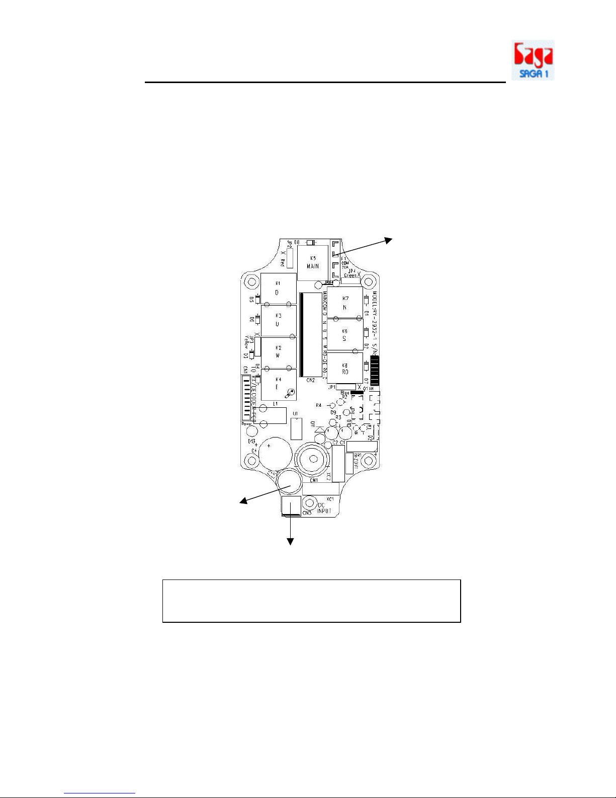
3.0
RECEIVER PCB DIAGRAM:
3-1. Relay Board for SAGA1-L8, L6, L4, L8B, L6B
3-1-1 DC Type
Fuse: 20A
(yellow color)
Fuse: 1.5A
DC Input
Remark: The polarity direction of DC Input isn’t required
when plugging in the power line connector.
SAGA1-L Series
6
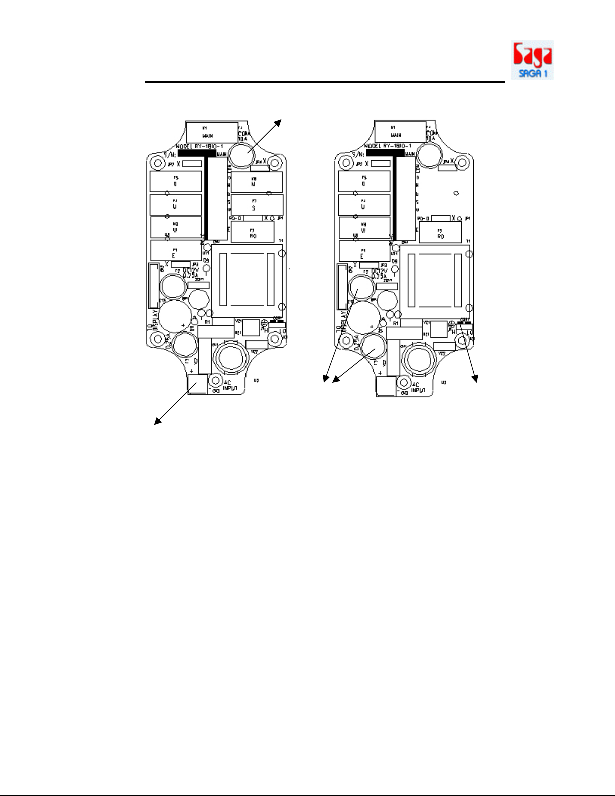
3-1-2 AC Type
SAGA1-L8, L8B, L6B
SAGA1-L6
Fuse: 10A
Fuse: 0.5A
Voltage selection
Jumper:
HI position to
select higher
volta
ge of the
combination,
LO position to
select lower
voltage of the
combination.
AC Input
 Loading...