

Saga PRO SERIES, SAG6000, SAG6002, SAG6003 Operation Manual
SAGA PRO SERIES STEREO
POWER AMPLIFIER
OPERATION MANUAL

INSTALLATION
Use care in unpacking the amplifier, and be sure to save the carton and packing materials so that you can use
them for moving, storing, or if you need to return the unit for service. Never place the unit in direct sunlight, in
excessive heat or humidity, in front of heating supply vents or extremely dusty locations. Make all connections
according to the instructions on the following pages.
FEATURES
• Saga Pro amplifiers deliver the following power ratings:
SAG6000: 250 watts @ 4 ohms / 150 watts @ 8 ohms
SAG6002: 450 watts @ 4 ohms / 350 watts @ 8 ohms
SAG6003: 800 watts @ 4 ohms / 550 watts @ 8 ohms
• 2-channel, Parallel or Bridged mono modes for flexible application
Other features include:
• Independent limiters for each channel, which decreases overload distortion
• Independent input level controls for each channel for volume setting
• Precise Signal and Clip LED indicators to monitor performance, enabling you to rectify overloading (clipping)
• Two forced-air fans keep the operating temperature low during use
• Inputs: XLR and 1/4-inch TRS
• Outputs: 5-way binding posts and Speakon® connectors
• Independent thermal overload protection for each channel, automatically guards amplifier and speakers
against damage or failure
• The housing can be mounted in any standard 19 inch rack
IMPORTANT SAFET Y INS TRU CTI O NS
Read safety and operating instructions before use, adhere to all warnings on the device and in these instructions,
and retain for future reference.
Do not use this device near water, or in a location near dripping or splashing liquid. Do not place objects that
contain liquid on or near the amplifier. Do not use water or any other liquid to clean the device. Use only a dry
soft cloth.
Do not block any ventilation openings, and locate device in a well-ventilated area.
Do not locate or operate device near heat sources or other devices (including amplifiers) that produce heat.
This amplifier has been provided with a polarized or grounding plug. Do not counteract the purpose of these safety
features. If the provided plug does not fit into your outlet, consult an electrician for replacement of the obsolete
outlet.
WARNING: The main plug or amplifier inlet is used as a disconnect device, and should remain readily operable.
Make sure the cord is not subject to being walked on, or pinched at the convenience receptacles or plugs, or at
the point of attachment to the amplifier.
Use only accessories that have been specified by the manufacturer.
Use this amplifier only with racks/carts rated for this type of equipment. Use caution when moving to prevent
tipping or injury.
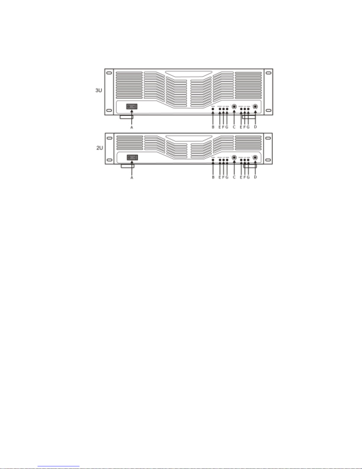
1. Saga Pro Series Front Panel
A: Power Switch “I”= on / “O”= off
This switch powers the unit on and off.
B: Power ON LED indicator
This light indicates that the power is on.
C: Ch A Input Level Control
D: Ch B Input Level Control
These controls adjust the input level for their respective channels. In Bridge Mono Mode,
only channel A level control is used to adjust signal level. In Parallel Mode, both input level
controls are used to adjust signal level for their respective amplifier channels. At the fully
counter-clockwise position, the signal is attenuated by more than 80dB. At their fully
clockwise position, the signal is at maximum gain.
E: Protection LED indicator
These LEDs indicate that the channel is in PROTECT mode. These LEDs will light when
overheating or other sever problems occur. When in protect mode, all output for that channel
will be muted, to protect any speakers connected to the channel.
F: Clip LED indicator
These LEDs indicate signal outside of the amplification range of the amplifier. They will
illuminate at the clipping threshold. When a signal is “clipped” it means that the signal is being
distorted at the output stage. These lights should not light up during normal use. If the clip
indicator is illuminated, lower the channel gain or input signal until the indicator light goes out.
NOTE: Prolonged clipping can damage your amplifier and speakers. Monitor the clip indicator
carefully during setup and use.
G: Signal LED indicator
These LED’s indicate that a signal is present at the amplifier input, and that the signal is being
amplified.
 Loading...