


www.saftronics.com
TECHNICAL MANUAL
VG5
REV2 (9/98)
P/N 027-2040
1998

PREFACE
The VG5 Series of general-purpose Inverters provides V/f Control and Vector Control as standard features along with user-friendly operation.
This manual is designed to ensure correct and suitable application of the VG5 Series Inverters. Read this manual before attempting to install,
operate, maintain, or inspect an Inverter and keep it in a safe, convenient location for future reference. Make sure you understand all
precautions and safety information before attempting any application.
Saftronics, 1998
All rights reserved. No part of this publication may be reproduced, stored in a retrieval system, or transmitted, in any form, or by any means,
mechanical, electronic, photocopying, recording, or otherwise, without the prior written permission of Saftronics. No patent liability is assumed
with respect to the use of the information contained herein. Moreover, because Saftronics is constantly striving to improve its high-quality
products, the information contained in this manual is subject to change without notice. Every precaution has been taken in the preparation of
this manual. Nevertheless, Saftronics assumes no responsibility for errors or omissions. Neither is any liability assumed for damages
resulting from the use of the information contained in this publication.
Firmware – S1043
Revision: 2 (9/98) i © Saftronics, Inc.

PREFACE
Safety Information
The following conventions are used to indicate precautions in this manual. Failure to follow the precautions provided in this manual can result
in serious or possible even fatal injury or damage to the products or to related equipment and systems.
WARNING
CAUTION
The warning symbols for ISO and JIS standards are different, as shown below.
ISO JIS
The ISO symbol is used in this manual. Both of these symbols appear on warning labels on Saftronics products. Please abide by these
warning labels regardless of which symbol is used.
Indicates precautions that, if not followed, could possibly result in loss of life or serious injury.
Indicates precautions that, if not followed, could result in serious injury, damage to the product,
or faulty operation.
Visual Aids
The following aids are used to indicate certain types of information for easier reference.
‘‘EXAMPLE•• Indicates application examples.
NOTE: Indicates important information that should be memorized.
General Precautions
• The diagrams in this manual may be indicated without covers or safety shields to show details. Be sure to restore covers or shields
before operating the units and run the units according to the instructions described in this manual.
• Any illustrations, photographs, or examples used in this manual are provided as examples only and may not apply to all products to
which this manual is applicable.
• The products and specifications described in this manual or the content and presentation of the manual may be changed without notice
to improve the product and/or the manual.
• When ordering a new copy of the manual due to damage or loss, contact your Saftronics representatives or the nearest Saftronics sales
office and provide the manual number shown on the front cover.
• If nameplates become warn or damaged, order new ones from your Saftronics representatives or the nearest Saftronics sales office.
Firmware – S1043
Revision: 2 (9/98) ii © Saftronics, Inc.

PREFACE
•
•
•
•
•
•
•
•
•
•
•
Safety Precautions
§ Confirmations upon Delivery
CAUTION
• Never install an Inverter that is damaged or missing components. Doing so can result in injury.
§ Installation
CAUTION
Always hold the case when carrying the Inverter. If the Inverter is held by the front cover, the main body of the Inverter
may fall, possibly resulting in injury.
Attach the Inverter to a metal or other noncombustible material. Fire can result in the Inverter if attached to a
combustible material.
Install a cooling fan or other cooling device when installing more than one Inverter in the same enclosure so that the
temperature of the air entering the Inverters is below 45°C. Overheating can result in fires or other accidents.
§ Wiring
Page
10
Page
14
14
14
WARNING
• Always turn OFF the input power supply before wiring terminals. Otherwise, an electric shock or fire can occur.
Wiring must be performed by an authorized person qualified in electrical work. Otherwise, an electric shock or fire can
occur.
Be sure to ground the ground terminal. (200 V class: Ground to 100 × or less, 400 V class: Ground to 10 × or less)
Otherwise, an electric shock or fire can occur.
Always check the operation of any emergency stop circuits after they are wired. Otherwise, there is the possibility of
injury. (Wiring is the responsibility of the user.)
Never touch the output terminals directly with your hands or allow the output lines to come into contact with the Inverter
case. Never short the output circuits. Otherwise, electrical shock or grounding can occur.
CAUTION
Check to be sure that the voltage of the main AC power supply satisfies the rated voltage of the Inverter. Injury or fire
can occur if the voltage is not correct.
Do not perform voltage withstand tests on the Inverter. Otherwise, semiconductor elements and other devices can be
damaged.
Connect braking resistors, Braking Resistor Units, and Braking Units as shown in the I/O wiring examples. Otherwise, a
fire can occur.
• Tighten all terminal screws to the specified tightening torque. Otherwise, a fire may occur.
Do not connect AC power to output Terminal T1, T2, and T3 (U, V, and W). The interior parts of the Inverter will be
damaged if voltage is applied to the output terminals.
Page
20
20
20
20
20
Page
20
20
20
20
20
Firmware – S1043
Revision: 2 (9/98) iii © Saftronics, Inc.

PREFACE
•
•
•
•
•
•
•
•
•
•
CAUTION
Do not connect Power Factor Correction Capacitors or LC/RC noise filters to the output circuits. The Inverter can be
damaged or internal parts burnt if these devices are connected.
Do not connect electromagnetic switches or contactors to the output circuits. If a load is connected while the Inverter is
operating, surge current will cause the overcurrent protection circuit inside the Inverter to operate.
§ Setting User Constants
CAUTION
Disconnect the load (machine, device) from the motor before Auto-Tuning. The motor may turn, possibly resulting in
injury or damage to equipment. Also, motor constants cannot be correctly set with the motor attached to a load.
§ Trial Operation
WARNING
Check to be sure that the front cover is attached before turning ON the power supply. Do not remove the front cover
during operation. An electric shock may occur.
Do not come close to the machine when the fault reset function is used. If the alarm is cleared, the machine may start
moving suddenly. Also, design the machine so that human safety is ensured even when it is restarted. Injury may
occur.
Provide a separate emergency stop switch; the Digital Operator STOP key is valid only when the function is set. Injury
may occur.
Reset alarms only after confirming that the RUN signal is OFF. If an alarm is reset with the RUN signal turned ON, the
machine may suddenly start. Injury may occur.
Page
20
20
Page
81
Page
86
86
86
86
Do not touch the radiation fins (heat sink), braking resistor, or Braking Resistor Unit. These can become very hot.
Otherwise, a burn injury may occur.
Be sure that the motor and machine is within the applicable ranges before starting operation. Otherwise, an injury may
occur.
• Provide a separate holding brake if necessary. Otherwise, an injury may occur.
• Do not check signals while the Inverter is running. Otherwise, the equipment may be damaged.
Be careful when changing Inverter settings. The Inverter is factory set to suitable settings. Otherwise, the equipment
may be damaged. You must, however, you must set the power supply voltage jumper for 400 V class Inverters of 18.5
kW or higher (See Chapter 5, 5.2.4 Setting Input Voltage).
Firmware – S1043
Revision: 2 (9/98) iv © Saftronics, Inc.
CAUTION
Page
86
86
86
86
86

PREFACE
•
•
•
•
•
•
§ Maintenance and Inspection
WARNING
Do not touch the Inverter terminals. Some of the terminals carry high voltages and are extremely dangerous. Doing so
can result in electric shock.
Always have the protective cover in place when power is being supplied to the Inverter. When attaching the cover,
always turn OFF power to the Inverter through the MCCB. Doing so can result in electric shock.
After turning OFF the main circuit power supply, wait until the CHARGE indicator light goes out before performance
maintenance or inspections. The capacitor will remain charged and is dangerous.
Maintenance, inspection, and replacement of parts must be performed only by authorized personnel. Remove all metal
objects, such as watches and rings, before starting work. Always use grounded tools. Failure to heed these warnings
can result in electric shock.
CAUTION
A CMOS IC is used in the control board. Handle the control board and CMOS IC carefully. The CMOS IC can be
destroyed by static electricity if touched directly.
Do not change the wiring, or remove connectors or the Digital Operator, during operation. Doing so can result in
personal injury.
Page
276
276
276
276
Page
276
276
§ Other
WARNING
• Do not attempt to modify or alter the Inverter. Doing so can result in electrical shock or injury.
Firmware – S1043
Revision: 2 (9/98) v © Saftronics, Inc.

PREFACE
How to Change the Digital Operator Display from Japanese to English
If the Digital Operator displays messages in Japanese, change to the English mode using the following steps. (This manual provides
descriptions for the English mode.)
Firmware – S1043
Revision: 2 (9/98) vi © Saftronics, Inc.

Table of Contents
1 Introduction .......................................................................................... 1
1.1 Outline and Functions.................................................................................... 2
1.2 Nomenclature ............................................................................................. 6
2 Handling Inverters................................................................................ 9
2.1 Confirmations upon Delivery.......................................................................... 10
2.2 Exterior and Mounting Dimensions................................................................. 12
1.1.1 VG5 Inverter Models ........................................................................................................... 2
1.1.2 Outline of Control Methods................................................................................................. 3
1.1.3 Functions............................................................................................................................. 3
1.2.1 VG5 Components................................................................................................................ 6
1.2.2 Digital Operator Components ............................................................................................. 7
2.1.1 Nameplate Information ........................................................................................................ 10
2.3 Checking and Controlling the Installation Site................................................. 14
2.3.1 Installation on Site............................................................................................................... 14
2.3.2 Controlling the Ambient Temperature................................................................................. 14
2.3.3 Protecting the Inverter from Foreign Matter ....................................................................... 14
2.4 Installation Orientation and Space.................................................................. 15
2.5 Removing/Attaching the Digital Operator and Front Cover.............................. 16
2.5.1 Inverters of 15 kW or Less.................................................................................................. 16
2.5.2 Inverters of 18.5 kW or Higher ............................................................................................ 17
3 Wiring .......................................................................................... 19
3.1 Connections to Peripheral Devices................................................................. 21
3.2 Connection Diagram...................................................................................... 22
3.3 Terminal Block Configuration......................................................................... 23
3.4 Wiring Main Circuit Terminals ........................................................................ 24
3.5 Wiring Control Circuit Terminals..................................................................... 39
3.6 Wiring Check................................................................................................. 42
3.4.1 Applicable Wire Sizes and Closed-Loop Connectors ........................................................ 24
3.4.2 Main Circuit Terminal Functions......................................................................................... 29
3.4.3 Main Circuit Configurations................................................................................................. 30
3.4.4 Standard Connection Diagrams.......................................................................................... 32
3.4.5 Wiring the Main Circuits...................................................................................................... 33
3.5.1 Wire Sizes and Closed-loop Connectors............................................................................ 39
3.5.2 Control Circuit Terminal Functions ..................................................................................... 40
3.5.3 Control Circuit Terminal Connections (All Models)............................................................ 41
3.5.4 Control Circuit Wiring Precautions...................................................................................... 42
3.7 Installing and Wiring PG Speed Option Cards................................................ 43
4 Setting User Constants........................................................................ 53
4.1 Using the Digital Operator.............................................................................. 54
4.2 Modes ......................................................................................................... 56
Firmware – S1043
Revision: 2 (9/98) vii © Saftronics, Inc.
3.7.1 Installing a PG Speed Option Card..................................................................................... 43
3.7.2 PG Speed Option Card Terminal Blocks............................................................................ 44
3.7.3 Wiring a PG Speed Option Card......................................................................................... 45
3.7.4 Wiring PG Speed Option Card Terminal Blocks ................................................................ 49
3.7.5 Selecting the Number of PG Pulses................................................................................... 51
4.2.1 Inverter Modes..................................................................................................................... 56
4.2.2 Switching Modes ................................................................................................................. 57
4.2.3 User Constant Access Levels............................................................................................. 58
4.2.4 Operation Mode................................................................................................................... 63
4.2.5 Initialize Mode...................................................................................................................... 70
4.2.6 Programming Mode ............................................................................................................. 77
4.2.7 Auto-Tuning Mode ............................................................................................................... 81
4.2.8 Modified Constants Mode ................................................................................................... 83

5 Trial Operation....................................................................................... 85
5.1 Procedure...................................................................................................... 57
5.2 Trial Operation Procedures............................................................................. 88
5.2.1 Power ON............................................................................................................................ 88
5.2.2 Checking the Display Status............................................................................................... 88
5.2.3 Initializing Constants........................................................................................................... 88
5.2.4 Setting Input Voltage........................................................................................................... 89
5.2.5 Auto-Tuning......................................................................................................................... 90
5.2.6 No-Load Operation.............................................................................................................. 93
5.2.7 Loaded Operation ............................................................................................................... 94
6 Basic Operation..................................................................................... 95
6.1 Common Settings........................................................................................... 96
6.1.1 Setting the Access Level and Control Method: A1-01, A1-02.......................................... 96
6.1.2 Frequency Reference Settings: b1-01, H3-01, H3-08, H3-09.......................................... 98
6.1.3 Frequency reference from Digital Operator: b1-01, o1-03, d1-01, to d1-09.................... 101
6.1.4 Run Source and Sequence Input Responsiveness: b1-02, b1-06, b1-07 ....................... 103
6.1.5 Acceleration/Deceleration Times: C1-01 through C1-08, C1-09, C1-10 C1-11 .............. 104
6.1.6 Prohibiting Reverse Operation: b1-04................................................................................ 105
6.1.7 Selecting the Stopping Method: b1-03.............................................................................. 106
6.1.8 Multi-Function Input Settings: H1-01 through H1-06........................................................ 107
6.2 Open-Loop Vector Control..............................................................................112
6.3 V/f Control......................................................................................................114
6.4 Flux Vector Control ........................................................................................121
6.5 V/f Control with PG.........................................................................................132
6.2.1 Auto-Tuning......................................................................................................................... 112
6.2.2 Auto-Tuning Faults.............................................................................................................. 113
6.3.1 Setting the Motor Constants: E1-01, E1-02, E2-01.......................................................... 114
6.3.2 V/f Pattern Selection: E1-03.............................................................................................. 115
6.4.1 PG Speed Option Card Settings ........................................................................................ 121
6.4.2 Setting the Zero Speed Operation Constants.................................................................... 124
6.4.3 Auto-Tuning......................................................................................................................... 126
6.4.4 Speed Control (ASR) Structure.......................................................................................... 128
6.4.5 Speed Control (ASR) Gain ................................................................................................. 130
6.5.1 Motor Constants: E1-01, E1-02, E2-01, E2-04................................................................. 132
6.5.2 V/f Pattern Selection: E1-03.............................................................................................. 133
6.5.3 PG Speed Option Card Settings ........................................................................................ 134
6.5.4 Speed Control (ASR) Structure.......................................................................................... 136
6.5.5 Adjusting Speed Control (ASR) Gain................................................................................. 137
7 Advanced Operation.............................................................................139
7.1 Open-Loop Vector Control..............................................................................140
7.2 Normal V/f Control..........................................................................................146
7.3 Flux Vector Control ........................................................................................150
7.4 V/f Control with PG Feedback.........................................................................165
Firmware – S1043
Revision: 2 (9/98) viii © Saftronics, Inc.
7.1.1 Torque Limit Function......................................................................................................... 141
7.1.2 Adjusting Speed Feedback................................................................................................. 143
7.1.3 Setting/Adjusting Motor Constants..................................................................................... 143
7.2.1 Energy Saving Control Function......................................................................................... 147
7.2.2 Hunting Prevention Function .............................................................................................. 148
7.2.3 Setting Motor Constants..................................................................................................... 149
7.3.1 Droop Control Function....................................................................................................... 151
7.3.2 Zero Servo Function ........................................................................................................... 152
7.3.3 Torque Control .................................................................................................................... 153
7.3.4 Speed/Torque Control Switching Function ........................................................................ 159
7.3.5 Torque Limit Function......................................................................................................... 160
7.3.6 Setting/Adjusting Motor Constants..................................................................................... 162
7.4.1 Energy Saving Control Function......................................................................................... 166
7.4.2 Hunting Prevention Function .............................................................................................. 167
7.4.3 Setting Motor Constants..................................................................................................... 168

7.5 Common Functions........................................................................................ 169
7.5.1 Application Constants: b .................................................................................................... 170
7.5.2 Tuning Constants: C........................................................................................................... 178
7.5.3 Reference Constants: d ..................................................................................................... 181
7.5.4 Option Constants: F ........................................................................................................... 183
7.5.5 External Terminal Functions: H ......................................................................................... 187
7.5.6 Protective Functions: L....................................................................................................... 204
7.5.7 Operator Constants: o ........................................................................................................ 215
8 User Constants ............................................................................... 219
8.1 Initialize Mode Constants............................................................................... 221
8.2 Programming Mode Constants....................................................................... 222
8.2.1 Application Constants: b .................................................................................................... 222
8.2.2 Auto-Tuning Constants: C.................................................................................................. 227
8.2.3 Reference Constants: d ..................................................................................................... 233
8.2.4 Motor Constant Constants: E............................................................................................. 236
8.2.5 Options Constants: F.......................................................................................................... 240
8.2.6 Terminal Constants: H ....................................................................................................... 243
8.2.7 Protection Constants: L...................................................................................................... 249
8.2.8 Operator Constants: o ........................................................................................................ 255
8.2.9 Factory Settings that Change with the Control Method (A1-02)........................................ 257
8.2.10 Factory Settings that Change with the Inverter Capacity (o2-04)...................................... 258
9 Troubleshooting ............................................................................... 261
9.1 Protective and Diagnostic Functions .............................................................. 262
9.1.1 Fault Detection .................................................................................................................... 262
9.1.2 Minor Fault Detection.......................................................................................................... 265
9.1.3 Operation Errors.................................................................................................................. 267
9.2 Troubleshooting............................................................................................. 268
9.2.1 If Constant Constants Cannot Be Set................................................................................. 268
9.2.2 If the Motor Does Not Operate............................................................................................ 268
9.2.3 If the Direction of the Motor Rotation is Reversed............................................................. 270
9.2.4 If the Motor Does Not Put Out Torque or If Acceleration is Slow...................................... 270
9.2.5 If the Motor Does Not Operate According to Reference.................................................... 270
9.2.6 If the Slip Compensation Function Has Low Speed Precision .......................................... 270
9.2.7 If There is Low Speed Control Accuracy at High-speed Rotation in Open-
9.2.8 If Motor Deceleration is Slow.............................................................................................. 271
9.2.9 If the Motor Overheats ........................................................................................................ 271
9.2.10 If There is Noise When the Inverter is Started or From an AM Radio............................... 272
9.2.11 If the Ground Fault Interrupter Operates When the Inverter is Run.................................. 272
9.2.12 If There is Mechanical Oscillation....................................................................................... 272
9.2.13 If the Motor Rotates Even When Inverter Output is Stopped ............................................ 273
9.2.14 If 0 V is Detected When the Fan is Started, or Fan Stalls ................................................. 273
9.2.15 If Output Frequency Does Not Rise to Frequency Reference........................................... 273
Loop Vector Control Mode.................................................................................................. 271
10 Maintenance and Inspection ............................................................... 275
10.1 Maintenance and Inspection .......................................................................... 277
11 Specifications....................................................................................... 279
11.1 Standard Inverter Specifications..................................................................... 280
11.2 Specifications of Options and Peripheral Devices........................................... 284
12 Appendix............................................................................................... 287
12.1 Inverter Application Precautions ..................................................................... 288
Firmware – S1043
Revision: 2 (9/98) ix © Saftronics, Inc.
10.1.1 Daily Inspection ................................................................................................................... 277
10.1.2 Periodic Inspection.............................................................................................................. 277
10.1.3 Periodic Maintenance of Parts............................................................................................ 277
12.1.1 Selection ............................................................................................................................. 288
12.1.2 Installation............................................................................................................................ 288
12.1.3 Settings ............................................................................................................................. 288
12.1.4 Handling ............................................................................................................................. 289

12.2 Motor Application Precautions........................................................................289
12.2.1 Using the Inverter for an Existing Standard Motor ............................................................. 289
12.2.2 Using the Inverter for Special Motors................................................................................. 290
12.2.3 Power Transmission Mechanism (Speed Reducers, Belts, and Chains) ......................... 290
12.3 Peripheral Device Application Precautions......................................................291
12.4 Wiring Examples............................................................................................292
12.4.1 Using a Braking Resistor Unit............................................................................................. 292
12.4.2 Using a Braking Unit and a Braking Resistor Unit............................................................. 293
12.4.3 Using Three Braking Units in Parallel ................................................................................ 296
12.4.4 Using a JVOP-95-o, -96-o VS Operator ........................................................................... 299
12.4.5 Using an Open-collector Transistor for Operation Signals................................................ 300
12.4.6 Using Open-collector, contact Outputs .............................................................................. 300
12.5 User Constants .............................................................................................301
INDEX........................................................................................................................305
Firmware – S1043
Revision: 2 (9/98) x © Saftronics, Inc.

1
Introduction
This chapter provides an overview of the VG5 Inverter and describes its functions and components.
1.1 Outline and Functions.................................................... 2
1.1.1 VG5 Inverter Models........................................................................................... 2
1.1.2 Outline of Control Methods................................................................................. 3
1.1.3 Functions ............................................................................................................ 3
1.2 Nomenclature.................................................................. 6
1.2.1 VG5 Components ........................................................................................... 6
1.2.2 Digital Operator Components............................................................................. 7

Chapter 1: Introduction
1.1 Outline and Functions
The VG5 Inverter provides full-current Vector Control based on advanced control logic. An Auto-Tuning function is included for user
friendly Vector Control.
The Digital Operator provides a liquid crystal display that is 2 lines by 16 characters in size. User constant settings and monitor
items are easily read in interactive operations in either Japanese or English. (The display language can be changed by setting a
user constant.)
1.1.1 VG5 Inverter Models
VG5 Inverters are available in 200 and 400 V class models. These are listed in the following table. A total of 37 models
are available for motor capacities of 0.4 to 300 kW (0.5 ~ 400HP).
Maximum
Voltage
Class
200 V
Class
* Immediate delivery † Available from factory ‡ Manufactured upon order
Applicable
Motor
Output
(HP)
0.75 0.4 1.2 VG520P4 20P41q*
1.5 0.75 2.3 VG520P7 20P71q*
2 1.5 3.0 VG521P5 21P51q*
3 2.2 4.2 VG522P2 22P21q*
5 3.7 6.7 VG523P7 23P71q*
7.5 5.5 9.5 VG525P5 25P51q*
10 7.5 13 VG527P5 27P51q*
15 11 19 VG52011 20111q*
20 15 24 VG52015
25 18.5 30 VG52018 20180q* 20181q‡
30 22 37 VG52022 20220q* 20221q‡
40 30 50 VG52030 20300q† 20301q‡
50 37 61 VG52037 20370q† 20371q‡
60 45 70 VG52045 20450q† 20451q‡
75 55 85 VG52055 20550q† 20551q‡
100 75 110 VG52075 20750q‡ 20751q‡
Maximum
Applicable
Motor
Output
(kW)
Table 1.1 VG5 Inverter Models
VG5
Output
Capacity
(kVA)
Model Number
(Specify all required standards when ordering.)
Open Chassis Type
(IEC IP 00)
VG5qqqqqq
Remove the top and
bottom covers from the
models listed at the
Inverter Specifications
Enclosed Wall-Mounted Type
(IEC IP 20, NEMA 1)
VG5qqqqqq
right.
*
20151q*
Maximum
Voltage
Class
400 V
Class
* Immediate delivery † Available from factory ‡ Manufactured upon order
Applicable
Motor
Output
(HP)
1 0.4 1.4 VG540P4 40P41q*
2 0.75 2.6 VG540P7 40P71q*
3 1.5 3.7 VG541P5 41P51q*
4 2.2 4.7 VG542P2 42P21q*
5 3.7 6.1 VG543P7 43P71q*
7.5 4 8.4 VG544P0 44P01o*
10 5.5 11 VG545P5 45P51q*
15 7.5 14 VG547P5 47P51q*
20 11 21 VG54011 40111q*
25 15 26 VG54015
30 18.5 31 VG54018 40180q* 40181q‡
40 22 37 VG54022 40220q* 40221q‡
50 30 50 VG54030 40300q* 40301q‡
60 37 61 VG54037 40370q* 40371q‡
75 45 73 VG54045 40450q* 40451q‡
100 55 98 VG54055 40550q† 40551q‡
125 75 130 VG54075 40750q† 40751q‡
150 110 170 VG54110 41100q† 41101q‡
200 160 230 VG54160 41600q† 41601q‡
250 185 260 VG54185 41850q‡ —
350 220 340 VG54220 42200q‡ —
500 300 460 VG54300 43000q‡ —
Maximum
Applicable
Motor
Output
(kW)
Output
Capacity
(kVA)
VG5
Model Number
(Specify all required standards when ordering.)
Open Chassis Type
(IEC IP 00)
VG5qqqqqq
Remove the top and
bottom covers from the
models listed at the
Inverter Specifications
Enclosed Wall-Mounted Type
(IEC IP 20, NEMA 1)
VG5qqqqqq
right.
*
40151q*
Firmware – S1043
Revision: 2 (9/98) 2 © Saftronics, Inc.

1.1.2 Outline of Control Methods
The VG5 uses four control methods:
• Open-Loop Vector Control (factory setting)
• Flux Vector Control
• V/f Control without PG
• V/f Control with PG Feedback
Note: PG stands for pulse generator (encoder).
Vector Control is a method for removing interference with magnetic flux and torque, and controlling torque according to
references.
Current Vector Control independently controls magnetic flux current and torque current by simultaneously controlling the
motor primary current and phases. This ensures smooth rotation, high torque, and accurate speed/Torque Control at low
speeds.
Vector Control can be replaced by the conventional V/f Control system. If the motor constants required for Vector Control
are not known, the motor constants can be automatically set with Auto-Tuning.
The control methods are effective for the following applications:
• Open-Loop Vector Control: General variable-speed drive.
• Flux Vector Control: Simple servo-drive, high-precision speed control/Torque Control.
• V/f Control without PG: Conventional Inverter control mode. Used for multi-drive operation (connecting
• V/f Control with PG Feedback: Simple speed feedback control. (For applications with the PG connected to the
The control characteristics for each mode are shown in Table 1.2.
Table 1.2 Control Method Characteristics
Characteristic
Speed Control Range 1:100 1:1000 1:40 1:40
Speed Control
Precision
Initial Drive 150% at 1 Hz 150% at 0 r/min 150% at 3 Hz
Open-Loop Flux Vector Without PG With PG Feedback
Chapter 1: Introduction
multiple motors to one Inverter).
machine shaft rather than the motor shaft.)
Vector Control V/f Control
±0.2 % ±0.02 % ±2 to 3 % ±0.03 %
1.1.3 Functions
§ Auto-Tuning
Auto-Tuning is effective for Vector Control. It solves problems in applicable motor restrictions and difficult constant
settings. The motor constants are automatically set by entering a value from the motor’s rating nameplate.
Auto-Tuning allows Flux Vector Control to operate accurately with virtually any normal AC induction motor,
regardless of the supplier.
§ Torque Control
Torque Control is effective for flux vector control with PG. Torque in controlled by taking multi-function analog input
signals as torque references. Torque Control accuracy is ±5%. Switching is possible between Torque Control and
speed control.
§ V/f Patter Settings
V/f pattern settings are effective for V/f Control. Select V/f pattern according to the application from among the 15
preset V/f patterns. Custom V/f patterns can also be set.
§ Frequency References
The following five types of frequency references can be used to control the output frequency of the Inverter:
• Numeric input from the Digital Operator
• Voltage input within a range from 0 to 10 V
• Voltage input within a range from 0 to ±10 V (With negative voltages, rotation is in the opposite direction from
the run command.)
• Current input within the range from 4 to 20 mA
• Input from Output Card
Firmware – S1043
Revision: 2 (9/98) 3 © Saftronics, Inc.

Chapter 1: Introduction
Any of the above frequency references can be used by setting a constant.
A maximum of nine frequency references can be registered with the Inverter. With remote multi-step speed
reference inputs, the Inverter can operate in multi-step speed operation with a maximum of nine speed steps.
§ PID Control
The Inverter has a PID control loop for easy process control. Process control is an operational method in which the
Inverter varies the output frequency to match the feedback value from the sensor to a set target value.
Process control can be applied to a variety of operations, such as those listed below, depending on the variable
detected by the sensor.
• Speed Control: With a speed sensor, such as tach generator, the Inverter regulates the rotating speed
of the motor regardless of the load on the motor or synchronizes the rotating speed of
the motor with that of another motor.
• Pressure Control: With a pressure sensor, the Inverter performs constant pressure control.
• Flow-Rate Control: By sensing the flow-rate of a fluid, the Inverter performs precise flow-rate control.
• Temperature Control: With a temperature sensor, the Inverter performs temperature control by fan speed.
§ Zero Servo Control
Zero Servo control is effective with flux vector control. Even at a motor speed of zero (0 Hz), a torque of 150% of the
motor’s rated torque can be generated and the average servomotor holding power (stopping power) can be obtained.
§ Speed Control by Feedback
Speed control using feedback is effective with a PG. An optional PG Speed Option Card can be used to enable
feedback control for speeds, thereby improving speed control accuracy.
§ Dwell Function
By holding the output frequency for a constant time during acceleration and deceleration, acceleration and
deceleration can be performed without stepping out even when driving a motor with a large startup load.
§ Low Noise
The output transistor of the Inverter is an IGBT (Insulated Gate Bipolar Transistor). Using sine wave PWM with a
high frequency carrier, the motor does not generate metallic noise.
§ Monitor Function
The following items can be monitored with the Digital Operator: frequency reference, output frequency, output
current, motor speed, output voltage reference, main-circuit DC voltage, output power, torque reference, status of
input terminals, status of output terminals, operating status, total operating time, software number, speed deviation
value, PID feedback value, fault status, fault history, etc.
All types of data can be monitored even with multi-function analog output.
§ Bilingual Digital Operator
The Digital Operator can display either English or Japanese. The Digital Operator’s liquid crystal display provides a
16 character by 2-line display area.
Easy-to-read displays allow the advanced functions of the Inverter to be set in interactive operations to input
constants, monitoring items, etc. Change the constant setting to select the English display.
§ Harmonic Countermeasures (0.4 to 160 kW Models)
The VG5 Inverters up to 160 kW support DC Reactors to easily handle high frequency control guidelines.
• DC Reactors (optional) can be connected to 0.4 to 15 kW models.
• Models from 18.5 to 160 kW have a built-in DC reactor.
• An optional AC reactor can be connected to Inverters from 185 to 300 kW.
Firmware – S1043
Revision: 2 (9/98) 4 © Saftronics, Inc.

Chapter 1: Introduction
§ User Constant Structure and Three Access Levels
The VG5 has a number of user constants for setting various functions. These user constants are classified into a
hierarchy to make them easier to use.
The levels are as follows from top to bottom: Modes, Groups, Functions, and Constants. The access levels for the
user constants are shown in Table 1.3.
Table 1.3 Access Levels for User Constants
Level Contents
Classified according to operation
Operation: For operating the Inverter. (All kinds of monitoring are possible.)
Initialize: For selecting the language displayed at the Digital Operator, setting
Mode
Programming: For setting user constants for operation.
Auto-Tuning: For automatic calculation or setting constants. (Only under the Vector
Modified Constants: For referencing or monitoring changed constants after shipment.
Groups Classified by application.
Functions Classified by function. (See user constants.)
Constants Individual user constant settings.
The VG5 allows the following three access levels to be set in order to further simplify setting user constants. (An
access level is a range of user constants that can be referenced or set.)
Quick-Start Reads/sets user constants required for trial operation. (factory setting)
Basic Reads/sets user constants that are commonly used.
Advanced Reads/sets all the user constants that can be used.
In general, press the DATA/ENTER key to move from an upper to a lower level. This varies somewhat, however,
according to the access level, as shown in Figure. 1.1. For the Quick-Start access level, which has few user
constants that can be set, pressing the DATA/ENTER key jumps directly to the user constant level; whereas for the
advanced access level, which has many user constants, pressing the DATA/ENTER key first leads to the Group
level.
access levels, initialization, and the control modes.
Control mode.)
Firmware – S1043
Revision: 2 (9/98) 5 © Saftronics, Inc.
Figure 1.1 Access Level Structure

Chapter 1: Introduction
1.2 Nomenclature
This section provides the names of VG5 components, and the components and functions of the Digital Operator.
1.2.1 VG5 Components
The appearance of Inverter and the names of its components are shown in Figure 1.2.
Figure 1.2 Appearance of VG5, Model VG520P4 (200 V, 0.4 kW, 0.5HP)
A 200 V Class Inverter with 0.4 kW Output is shown below with the front cover removed.
Firmware – S1043
Revision: 2 (9/98) 6 © Saftronics, Inc.
Figure 1.3 Terminal Arrangement

1.2.2 Digital Operator Components
This section describes the component names and functions of the Digital Operator. The component names and functions
are shown in Figure 1.4 and key functions are described in Table 1.4.
Chapter 1: Introduction
Operation Mode Indicators
DRIVE: Lit when in Operation mode.
FWD: Lit when there is a forward run command input.
REV: Lit when there is a reverse run command input.
SEQ: Lit when the run command from the control circuit terminal is
enabled.
REF: Lit when the frequency reference from control circuit
Terminals 13 and 14 is enabled.
Data Display
Two-line LCD that displays data for monitoring, user constants and set
values with 16 characters per line.
Keys
Execute operations such as setting user constants, monitoring, Jog,
and Auto-Tuning.
Figure 1.4 Digital Operator Component Names and Functions
Firmware – S1043
Revision: 2 (9/98) 7 © Saftronics, Inc.

Chapter 1: Introduction
Table 1.4 Key Functions
Key Name Function
LOCAL/REMOTE Key
MENU Key Displays menus.
ESC Key Returns to the status before the DATE/ENTER key was pressed.
JOG Key Enables jog operation when the VG5 is being operated from the Digital Operator.
Switches between (LOCAL) operation via the Digital Operator and control circuit terminal
(REMOTE) operation. This key can be enabled or disabled by setting a user constant
(o2-01).
FWD/REV Key
RESET Key
Increment Key
Decrement Key
Selects the rotation direction of the motor when the VG5 is being operated from the
Digital Operator.
Sets the number of digits for user constant settings. Also acts as the reset key when a
fault has occurred.
Selects menu items, groups, functions, and user constant names, and decrements set
values.
Selects menu items, groups, functions, and user constant names, and decrements set
values.
DATA/ENTER Key Enters menu items, functions, constants, and set values after they are set.
RUN Key Starts the VG5 operation when the VG5 is in operation with the Digital Operator.
STOP Key
Stops VG5 operation. This key can be enabled or disabled by setting a user constant
(o2-02) when operating from the control circuit terminal.
Note: Except in diagrams, keys are referred to using the key names listed in the above table.
Figure 1.5 RUN and STOP Indicators
Firmware – S1043
Revision: 2 (9/98) 8 © Saftronics, Inc.

2
Handling Inverters
This chapter describes the checks required upon receiving a VG5 Inverter and describes installation
methods.
2.1 Confirmations upon Delivery......................................... 10
2.1.1 Nameplate Information....................................................................................... 10
2.2 Exterior and Mounting Dimensions............................... 12
2.3 Checking and Controlling the Installation Site............. 14
2.3.1 Installation Site.................................................................................................... 14
2.3.2 Controlling the Ambient Temperature................................................................ 14
2.3.3 Protecting the Inverter from Foreign Matter....................................................... 14
2.4 Installation Orientation and Space................................ 15
2.5 Removing/Attaching the Digital Operator and Front
Cover................................................................................ 16
2.5.1 Inverters of 15 kW or Less ................................................................................. 16
2.5.2 Inverters of 18.5 kW or Higher........................................................................... 17

Chapter 2: Handling Inverters
2.1 Confirmations Upon Delivery
CAUTION
• Never install an Inverter that is damaged or missing components. Doing so can result in injury.
Check the following items as soon as the Inverter is delivered.
Table 2.1 Checks
Has the correct model of Inverter been
Item Method
delivered?
Is the Inverter damaged in any way? Inspect the entire exterior of the Inverter to see if there are any scratches or other damage
Are any screws or other components loose? Use a screwdriver or other tools to check for tightness.
If you find any irregularities in the above items, contact the agency from which you purchased the Inverter or your Saftronics representative
immediately.
2.1.1 Nameplate Information
§ Example Nameplate
Standard domestic Inverter: 3-phase, 200VAC, 0.4 kW, IEC IP20 and NEMA 1 standards.
Check the model number on the nameplate on the side of the Inverter (See Nameplate
Information 2.1.1).
resulting from shipping.
Model number
Input specifications
Output specifications
Lot number
Serial number
MODEL : VG520P4 SPEC: 20P41A
INPUT : AC 3PH 200-230 V 50Hz
OUTPUT : AC 3PH 0-230 V 1.2kVA 3.2 A
LOT NO : MASS : 3.0kg
SER NO :
§ Inverter Model Numbers
VG5
UL/C-UL model
No.
2
4
D
E
Voltage Class
AC input, 3-phase, 200 V
AC input, 3-phase, 400 V
DC input, 3-phase, 200 V
DC input, 3-phase, 400 V
SAFTRONICS INC
VG5 2
200-230 V 60Hz
0P4
No.
Max. Motor Capacity
0P4
0P7
to
075
"P" indicates the decimal point.
Inverter specifications
Mass
0.75 kW
to
75 kW
Firmware – S1043
Revision: 2 (9/98) 10 © Saftronics, Inc.

Chapter 2: Handling Inverters
§ Inverter Specifications
No.
2
4
No.
0P4
0P7
to
075
"P" indicates the decimal point.
Voltage Class
AC input, 3-phase, 200 V
AC input, 3-phase, 400 V
Max. Motor Capacity
0.4 kW
0.75 kW
to
75 kW
• Open Chassis Type (IEC IP00)
Protected so that parts of the human body cannot reach electrically charged parts from the front when the
Inverter is mounted in a control panel.
• Enclosed Wall-Mounted Type (IEC IP20, NEMA 1)
The Inverter is structured so that the Inverter is shielded from the exterior, and can thus be mounted to the
interior wall of a standard building (not necessarily enclosed in a control panel). The protective structure
conforms to the standards of NEMA 1 in the USA.
2 0P4 A
1
Version (Enter the specifications form
number when special specifications are
required.)
No.
Protective Structure
0
Open Chassis (IEC IP00)
Enclosed Wall-Mounted (IEC iP20, NEMA 1)
1
Firmware – S1043
Revision: 2 (9/98) 11 © Saftronics, Inc.

2.2 Exterior and Mounting Dimensions
§ 200 V/400 V Class Inverters of 15 kW and Lower
The following diagram shows a 200 V class, 1.5 kW Inverter.
Remove the top and bottom covers when mounting 200 V/400 V class Inverters of 15 kW or lower in a control panel.
§ 200 V/400 V Class Inverters of 18.5 kW and Higher
Chapter 2: Handling Inverters
The following diagram shows a 200 V class, 18.5 kW Inverter.
§ Mounting Dimensions for 400 V Class Inverters of 185 to 300 kW
W4
W5 W6
Max. Applicable Motor
Capacity
[kW]
185, 220
W1 W2 W4W3 W5 W6
750 440 310 850 285 565
W2
W3
W1
Firmware – S1043
Revision: 2 (9/98) 12 © Saftronics, Inc.
300
750 440 310 873 298 575

Chapter 2: Handling Inverters
Table 2.2 VG5 External Dimensions (mm) and Approximate Masses (kg)
Open Chassis (IP00) Enclosed Wall-Mounted (NEMA 1)
Approx.
Mass
W H D W1 H1 H2
Approx.
Mass
Mounting
Holes
*1
d
DC
Reactor
*1
Voltage
Class
Max.
Applicable
Output
[kW]
W H D W1 H1 H2
0.4
0.75
140 280 160 126 266 7.0 3 140 280 160 126 266 7.0 3 M5
1.5
2.2
140 280 180 126 266 7.0 4.5 140 280 180 126 266 7.0 4.5 M5
200 V
Class
3.7
5.5 5.5 5.5
200 300 205 186 285 8.0
7.5
11 380 7.5
250 380 225 236 365 7.5 11 250
15
18.5 610 87.5
325 450 285 275 435 7.5 28 330
22
30 61 67
425 675 350 320 650 12.5
37
45
475 800 350 370 775 12.5 80 480 1110 350 370 775 212.5 87 M10
55
200 300 205 186 285 8.0
6
225 236 365
400
285 275 435
675
430 985 350 320 650 212.5
62
27.5
152.5
6
M6
11 M6
32 M6
68
M10
Option
Built-in
75 575 925 400 445 895 15.0 135 580 1290 400 445 895 270 145 M12
0.4
0.75
140 280 160 126 266 7.0 3 140 280 160 126 266 7.0 3 M5
1.5 4 4
2.2
140 280 180 126 266 7.0
3.7
5.5
200 300 205 186 285 8.0 6 200 300 205 186 285 8.0 6 M6
7.5
11
250 380 225 236 365 7.5 11 250 380 225 236 365 7.5 11 M6
15
18.5 29 32
400 V
Class
325 450 285 275 435 7.5
22
30
37
325 625 285 275 610 7.5 44 330
45
55 81 87
455 820 350 350 795 12.5
75
110 375 135 580 1290 375 445 895 270 145 M12
160
185
220
300 960 1600 455
*1
Same for open Chassis and enclosed wall-mounted types.
*2
See Page 12 for mounting dimensions.
575 925
400
950 1450 435
445 895 15.0
140
*2
0
155
*2
0
25 360
25 420
140 280 180 126 266 7.0
4.5
330 610 285 275 435 87.5
31
785 87.5
285 275 610
850
460 1130 350 350 795 212.5
82
152.5
4.5
34
48 M6
88
145 400 155
__ M12 _
M5
Option
M6
Built-in
M10
NOTE: An attachment is required to mount the cooling fins (fin section) on the outside of the control panel for 200 V/400 V class Inverters of
15 kW or less. Please ask your Saftronics representative for details. Dimensional drawings for models with externally mounted
cooling fins and other special requirements are also available from you Saftronics representative.
Firmware – S1043
Revision: 2 (9/98) 13 © Saftronics, Inc.

Chapter 2: Handling Inverters
•
2.3 Checking and Controlling the Installation Site
CAUTION
• Always hold the case when carrying the Inverter. If the Inverter is held by the front cover, the main body of the Inverter may fall,
possibly resulting in injury.
• Attach the Inverter to a metal or other noncombustible material. Fire can result if the Inverter is attached to a combustible material.
Install a cooling fan or other cooling device when installing more than one Inverter in the same enclosure so that the temperature of
the air entering the Inverters is below 45°C. Overheating can result in fire or other accidents.
Install the VG5 in the installation site described below and maintain optimum conditions.
2.3.1 Installation Site
Install the Inverter under the following conditions.
Enclosed wall-mounted -10 to 40°C 90% RH or less (no condensation)
Open chassis -10 to 45°C 90% RH or less (no condensation)
Protection covers are attached to the top and bottom of the Inverter. Be sure to remove the protection covers before
installing a 200 or 400 V class Inverter with an output of 5 kW or less in a panel.
• Install the Inverter in a clean location free from oil mist and dust. It can be installed in a totally enclosed panel that is
completely shielded from floating dust.
• When installing or operating the Inverter, always take special care so that metal powder, oil, water, or other foreign
matter does not get into the Inverter.
Type Ambient Operating Temperature Humidity
• Do no install the Inverter on combustible material, such as wood.
• Install the Inverter in a location free from radioactive materials and combustible materials.
• Install the Inverter in a location free from harmful gasses and liquids.
• Install the Inverter in a location without excessive oscillation.
• Install the Inverter in a location free from chlorides.
• Install the Inverter in a location not in direct sunlight.
2.3.2 Controlling the Ambient Temperature
To enhance the reliability of operation, the Inverter should be installed in an environment free from extreme temperature
increases. If the Inverter is installed in an enclosed environment, such as a box, use a cooling fan or air conditioner to
maintain the internal air temperature below 45°C.
2.3.3 Protecting the Inverter from Foreign Matter
Place a cover over the Inverter during installation to shield it from metal power produced by drilling.
Always remove the cover from the Inverter after completing installation. Otherwise, ventilation will be reduced, causing
the Inverter to overheat.
Firmware – S1043
Revision: 2 (9/98) 14 © Saftronics, Inc.

Chapter 2: Handling Inverters
•
•
•
2.4 Installation Orientation and Space
Install the Inverter on a vertical surface so as not to diminish its coding efficiency. When installing the Inverter, always provide the
following installation space to allow normal heat dissipation.
NOTE:
Figure 2.1 VG5 Installation Orientation and Space
The same space is required horizontally and vertically for both open chassis (IP00) and enclosed wall-mounted (IP20,
NEMA 1) Inverters.
Always remove the protection covers before installing a 200 or 400 V class Inverter with an output of 15 kW or less in a
panel.
Always provide enough space for suspension eyebolts and the main circuit lines when installing a 200 or 400 V class
Inverter with an output of 30 kW or more in a panel.
Firmware – S1043
Revision: 2 (9/98) 15 © Saftronics, Inc.

2.5 Removing/Attaching the Digital Operator and Front Cover
Remove the front cover to wire the terminals.
For models of 15 kW or less (both 200 V and 400 V class), do not remove or mount the front cover without first removing the Digital
Operator; otherwise, the Digital Operator may malfunction due to imperfect contact. Use the following procedures to remove or
attach the front cover.
2.5.1 Inverters of 15 kW or Less
§ Removing the Digital Operator
Press the lever on the side of the Digital Operator in the direction of arrow 1 to unlock the Digital Operator. Lift the
Digital Operator in the direction of arrow 2 to remove the Digital Operator as shown in the following illustration.
Chapter 2: Handling Inverters
Figure 2.2 Removing the Digital Operator
§ Removing the Front Cover
Press the left and right sides of the front cover in the directions of arrows 1 and lift the bottom of the cover in the
direction of arrow 2 to remove the front cover as shown in the following illustration.
Figure 2.3 Removing the Front Cover
§ Mounting the Front Cover
After wiring the terminals, mount the front cover to the Inverter by performing in reverse order the steps to remove
the front cover.
1. Do not mount the front cover with the Digital Operator attached to the front cover; otherwise, the Digital
Operator may malfunction due to imperfect contact.
2. Insert the tab of the upper part of the front cover into the groove of the Inverter and press the lower part of the
front cover onto the Inverter until the front cover snaps shut.
Firmware – S1043
Revision: 2 (9/98) 16 © Saftronics, Inc.

Chapter 2: Handling Inverters
•
•
§ Mounting the Digital Operator
1. Hook the Digital Operator at A (two locations) on the front cover in the direction of arrow 1 as shown in the
following illustration.
2. Press the Digital Operator in the direction of arrow 2 until it snaps in place at B (two locations).
Figure 2.4 Mounting the Digital Operator
NOTE:
Do not remove or attach the Digital Operator or mount or remove the front cover using methods other then those described
above, otherwise the Inverter may break or malfunction due to imperfect contact.
Never attach the front cover to the Inverter with the Digital Operator attached to the front cover. Imperfect contact can
result.
• Always attach the front cover to the Inverter itself first, and then attach the Digital Operator to the front cover.
2.5.2 Inverters of 18.5 kW or Higher
The front cover can be removed without removing the Digital Operator from the Inverter provided that the Inverter has an
output of 18.5 kW or higher.
Loosen the four screws of the front cover and move the front cover slightly upward to remove the front cover.
Firmware – S1043
Revision: 2 (9/98) 17 © Saftronics, Inc.

3
Wiring
This chapter describes wiring terminals, main circuit terminal connections, main circuit terminal wiring
specifications, control circuit terminals, and control circuit-wiring specifications.
3.1 Connections to Peripheral Devices............................... 21
3.2 Connection Diagram....................................................... 22
3.3 Terminal Block Configuration........................................ 23
3.4 Wiring Main Circuit Terminals ....................................... 24
3.4.1 Applicable Wire Sizes and Closed-Loop Connectors........................................ 24
3.4.2 Main Circuit Terminal Functions......................................................................... 29
3.4.3 Main Circuit Configurations ............................................................................... 30
3.4.4 Standard Connection Diagrams......................................................................... 32
3.4.5 Wiring the Main Circuits...................................................................................... 33
3.5 Wiring Control Circuit Terminals................................... 39
3.5.1 Wire Sizes and Closed-Loop Connectors.......................................................... 39
3.5.2 Control Circuit Terminal Functions..................................................................... 40
3.5.3 Control Circuit Terminal Connections (All Models)............................................ 41
3.5.4 Control Circuit Wiring Precautions..................................................................... 42
3.6 Wiring Check................................................................... 42
3.7 Installing and Wiring PG Speed Option Cards ............. 43
3.7.1 Installing a PG Speed Option Card.................................................................... 43
3.7.2 PG Speed Option Card Terminal Blocks........................................................... 44
3.7.3 Wiring a PG Speed Option Card........................................................................ 45
3.7.4 Wiring PG Speed Option Card Terminal Blocks................................................ 49
3.7.5 Selecting the Number of PG Pulses .................................................................. 51

Chapter 3: Wiring
•
•
•
•
•
•
•
WARNING
• Always turn OFF the input power supply before wiring terminals. Otherwise, an electric shock or fire can occur.
• Wiring must be performed by an authorized person qualified in electrical work. Otherwise, an electric shock or fire can occur.
Be sure to ground the ground terminal. (200 V class: Ground to 100 Ω or less, 400 V class: Ground to 10 Ω or less) Otherwise, an
electric shock or fire can occur.
Always check the operation of any emergency stop circuits after they are wired. Otherwise, there is the possibility of injury. (Wiring is
the responsibility of the user)
Never touch the output terminals directly with your hands or allow the output lines to come into contact with the Inverter case. Never
short the output circuits. Otherwise, electrical shock or grounding can occur.
CAUTION
Check to be sure that the voltage of the main AC power supply satisfies the rated voltage of the Inverter. Injury or fire can occur if the
voltage is not correct.
• Do not perform voltage withstand tests on the Inverter. Otherwise, semiconductor elements and other devices can be damaged.
• Connect braking resistors, Braking Resistor Units, and Braking Units as shown in the I/O wiring examples. Otherwise, a fire can occur.
• Tighten all terminal screws to the specified tightening torque. Otherwise a fire may occur.
Do not connect AC power to output Terminals T1, T2, and T3 (U, V, and W). The interior parts of the Inverter will be damaged if
voltage is applied to the output terminals.
Do not connect phase-advancing capacitors or LC/RC noise filters to the output circuits. The Inverter can be damaged or internal
parts burnt if these devices are connected.
Do not connect electromagnetic switches or contactors to the output circuits. If a load is connected while the Inverter is operating,
surge current will cause the overcurrent protection circuit inside the Inverter to operate.
Firmware – S1043
Revision: 2 (9/98) 20 © Saftronics, Inc.

3.1 Connections to Peripheral Devices
Examples of connections between the VG5 and typical peripheral devices are shown in Figure 3.1. Use this illustration to gain an
understanding of the overall equipment configuration.
Chapter 3: Wiring
Firmware – S1043
Revision: 2 (9/98) 21 © Saftronics, Inc.
Figure 3.1 Example Connections to Peripheral Devices

Chapter 3: Wiring
3.2 Connection Diagram
The connection diagram of the VG5 is shown in Figure 3.2.
When using the Digital Operator, the motor can be operated by wiring only the main circuits.
Figure 3.2 Connection Diagram (Model VG527P5 shown above)
Firmware – S1043
Revision: 2 (9/98) 22 © Saftronics, Inc.

Chapter 3: Wiring
NOTE: 1. Control circuit Terminals 1 to 33 are not arranged in order of terminal numbers; they are arranged as shown below.
Be sure to wire them correctly.
11 12(G) 13 14 15 16 17 25 26 27 33 18 19 20
1 2 3 4 5 6 7 8 21 22 23 9 10
2. Do not use control circuit Terminals 13 and 14 at the same time. (The two signals will be added inside the Inverter if
they are input at the same time.
3. The maximum output current capacity of the +15 V/-15 V output from control circuit Terminals 15 and 33 is 20 mA.
4. The multi-function analog output is a dedicated meter output for a frequency meter, ammeter, etc. Do not use this
output for Feedback Control or for any other control purpose. Use one of the optional analog monitors (AO-08 or
AO-012) for analog outputs to the control system.
5. Disable the Stall Prevention during deceleration (set constant L3-04 to 0) when using a Braking Resistor Unit. If this
user constant is not changed to disable Stall Prevention, the system may not stop during deceleration.
6. Enable protection for the internal DB resistor (model ERF) (set constant L8-01 to 1) when using an internal braking
resistor. The braking resistor will not be protected unless this setting is changed to enable protection.
7. DC Reactors to improve the input power factor can be connected as an option only to Inverters for 15 kW or less.
Remove the short bar from between ⊕1 and ⊕ 2 when connecting a DC Reactor.
8. There is no DC power supply input terminals for 200 V class Inverters of 30 to 75 kW and 400 V class Inverters of 55
to 160 kW, and DC power cannot be input to these Inverters.
3.3 Terminal Block Configuration
The terminal block for a 200 V class Inverter with an output of 0.4 kW is shown in Figure 3.3.
Firmware – S1043
Revision: 2 (9/98) 23 © Saftronics, Inc.
Figure 3.3 Terminal Arrangement

Chapter 3: Wiring
3.4 Wiring Main Circuit Terminals
3.4.1 Applicable Wire Sizes and Closed-Loop Connectors
Select the appropriate wires and crimp terminals from Table 3.1 to Table 3.3.
Table 3.1 200 V Class Wire Sizes
Circuit
VG5
Model
VG520P4 M4 14-10 2-5.5
L1, L2, L3, √, 1, 2, B1, B2, T1, T2, T3
Terminal Symbol
Terminal
Screws
AWG Sizes
Wire
Thickness
(see note)
2
mm
Wire Type
Main
Circuits
VG520P7 M4 14-10 2-5.5
VG521P5 M4
VG522P2 M4 12-10 3.5-5.5
VG523P7 M4 5.5
VG525P5 M5
VG527P5 M5
VG52011 M6
VG52015
VG52018
VG52022
VG52030
VG52037
L1, L2, L3, √, 1,, 2, B1, B2, T1, T2, T3
L1, L2, L3, √, 1, 2, B1, B2, T1, T2, T3
L1, L2, L3, √, 1, 2, B1, B2, T1, T2, T3
L1, L2, L3, √, 1, 2, B1, B2, T1, T2, T3
L1, L2, L3, √, 1, 2, B1, B2, T1, T2, T3 8 8
L1, L2, L3, √, 1, 2, B1, B2, T1, T2, T3
L1, L2, L3, √, 1, 2, 3, T1, T2, T3 4 22
L1, L2, L3, √, 1, 2, 3, T1, T2, T3
L1, L2, L3, √, 1, 2, 3, T1, T2, T3 3 30
r, s
L1, L2, L3, √, 1, 2, 3 T1, T2, T3
r, s
L1, L2, L3, √, 3, T1, T2, T3 M10 4/0 38-100
r, s
L1, L2, L3, √, 3, T1, T2, T3
r, s
M8 3 30
M6 8 8
M8
M4 20-10 0.5-5.5
M8
M4 20-10 0.5-5.5
M8 4 22
M4 20-10 0.5-5.5
M10 1/0 x 2P 38- 100
M8 4 22
M4 20-10 0.5-5.5
14-10 2-5.5
12-10 3.5-5.5
10
10-8 5.5- 8
8 8
10-8 5.5-8
8 8
6 14
2 38
6 14
Power cables, e.g.,
600V vinyl power
cables
NOTE: The wire thickness is set for copper wires at 75°C.
Firmware – S1043
Revision: 2 (9/98) 24 © Saftronics, Inc.

Chapter 3: Wiring
Circuit
VG5
Model
Terminal Symbol
L1, L2, L3, √, 3, T1, T2, T3
VG52045
r, s
L1, L2, L3, √, 3, T1, T2, T3
Main
Circuits
VG52055
r, s
L1, L2, L3, √, 3, T1, T2, T3
VG52075
r, s
Control
Circuits
All models 1 to 33 M3.5 20-16 0.5-2
NOTE: The wire thickness is set for copper wires at 75°C.
Terminal
Screws
AWG Sizes
Thickness
(see note)
M10 1/0 x 2P 60-100
M8 4 22
M4 20-10 0.5-5.5
M10 1/0 x 2P 100
M8 3 30
M4 20-10 0.5-5.5
M12 4/0 x 2P 100-200
M8 1 50
M4 20-10 0.5-5.5
Wire
mm
2
Wire Type
Power cables, e.g.,
600V vinyl power
cables
Shielded twisted-pair
wires
Firmware – S1043
Revision: 2 (9/98) 25 © Saftronics, Inc.

Chapter 3: Wiring
Table 3.2 400 V Class Wire Sizes
Circuit VG5 Model Terminal Symbol
L1, L2, L3, √, 1, 2, B1, B2, T1, T2, T3
L1, L2, L3, √, 1, 2, B1, B2, T1, T2, T3
L1, L2, L3, √, 1, 2, B1, B2, T1, T2, T3
L1, L2, L3, √, 1, 2, B1, B2, T1, T2, T3
L1, L2, L3, √, 1, 2, B1, B2, T1, T2, T3
L1, L2, L3, √, 1, 2, B1, B2, T1, T2, T3
L1, L2, L3, √, 1, 2, B1, B2, T1, T2, T3
L1, L2, L3, √, 1, 2, B1, B2, T1, T2, T3
L1, L2, L3, √, 1, 2, B1, B2, T1, T2, T3
L1, L2, L3, √, 1, 2, B1, B2, T1, T2, T3 M5 8-6 8-14
L1, L2, L3, √, 1, 2, 3, T1, T2, T3
Main
Circuits
VG540P4 M4 14-10 2-5.5
VG540P7 M4
VG541P5 M4
VG542P2 M4
VG543P7 M4
VG44P0 M4 12-10 3.5-5.5
VG545P5 M4 12-10 3.5-5.5
VG547P5 M5 8-6 8-14
VG54011
VG54015
VG54018
r, s
L1, L2, L3, √, 1, 2, 3, T1, T2, T3 M6 4 22
VG54022
r, s
L1, L2, L3, √, 1, 2, 3, T1, T2, T3
VG54030
r, s
L1, L2, L3, √, 1, 2, 3, T1, T2, T3 3 30
VG54037
r, s
L1, L2, L3, √, 1, 2, 3, T1, T2, T3
VG54045
r, s
L1, L2, L3, √, 3, T1, T2, T3
VG54055
r, s 200, s 400
Terminal
Screws
AWG Sizes
Thickness
(see note)
14-10 2-5.5
12-10 3.5-5.5
14-10 2-5.5
12-10 3.5-5.5
14-10 2-5.5
12-10 3.5-5.5
14-10 2-5.5
12-10 3.5-5.5
M5 8-6 8-14
M6 8 88
M6 8 8
M6 6 14
M8 8 8
M4 20-10 0.5-5.5
M8 8 8
M4 20-10 0.5-5.5
M8
4 22
8 8
M4 20-10 0.5-5.5
M8
6 14
M4 20-10 0.5-5.5
M8
1 50
6 14
M4 20-10 0.5-5.5
M10 4/0 38-100
M8 4 22
M4 20-10 0.5-5.5
Wire
mm
2
Wire Type
Power cables,
e.g., 600 V vinyl
power cables
NOTE: The wire thickness is set for copper wires at 75°C.
Firmware – S1043
Revision: 2 (9/98) 26 © Saftronics, Inc.

Chapter 3: Wiring
Circuit
VG5
Model
Terminal Symbol
L1, L2, L3, √, 3, T1, T2, T3
VG54075
r, s 200, s 400
L1, L2, L3, √, 3, T1, T2, T3
VG54110
r, s 200, s 400
L1, L2, L3, √, 3, T1, T2, T3
VG54160
Main
Circuits
r, s 200, s 400
L1, L2, L3, √, 1, 3, T1, T2, T3
VG54185
r, s 200, s 400
L1, L2, L3, √, 1, 3, T1, T2, T3
VG54220
r, s 200, s 400
L1, L2, L3, √, 1, 3, T1, T2, T3
VG54300
r, s 200, s 400
Control
Circuits
All models
1 to 33 M3.5 20-16 0.5-2
G M3.5 20-14 0.5-2
NOTE: The wire thickness is set for copper wires at 75°C.
Terminal
Screws
AWG Sizes
Thickness
(see note)
M10 1/0 x 2P 100
M8 4 22
M4 20-10 0.5-5.5
M10 1/0 x 2P 60-100
M8 3 30
M4 20-10 0.5-5.5
M12 4/0 x 2P 100 x 2P
M8 1 50
M4 20-10 0.5-5.5
M16 650MCM x 2P 325 X 2p
M8 1 50
M4 20-10 0.5-5.5
M16 650MCM x 2P 325
M8 1/0 60
M4 20-10 0.5-5.5
M16 650MCM x 2P 325 x 2P
M8 1/0 60
M4 20-10 0.5- 5.5
Wire
mm
2
Wire Type
Power cables,
e.g., 600 V vinyl
power cables
Shielded twisted-
pair wires
Firmware – S1043
Revision: 2 (9/98) 27 © Saftronics, Inc.

Chapter 3: Wiring
AWG Sizes Wire Thickness mm
12-10 3.5/5.5
300MCM 150 150-12
400MCM 200
650MCM 325
NOTE: Determine the wire size for the main circuit so that line voltage drop is within 2% of the rated voltage. Line voltage
Table 3.3 Closed-Loop Connector Sizes (JIS C 2805) (For 200 V and 400 V Classes)
2
20 0.5
18 0.75
16 1.25
Terminal Screws Size
M3.5 1.25-3.5
M4 1.25-4
M3.5 1.25-3.5
M4 1.25-4
M3.5 1.25-3.5
M4 1.25-4
M3.5 2-3.5
M4 2-4
14 M8
M5 2-5
M6 2-6
M8 2-8
M4 5.5-4
M5 5.5-5
M6 5.5-6
M8 5.5-8
M5 8-5
8 8
M6 8-6
M8 8-8
6 14
4 22
M6 14-6
M8 14-8
M6 22-6
M8 22-8
3-2 30/38 M8 38-8
1-1/0 50/60
3/0 80 80-10
4/0 100
M8 60-8
M10 60-10
M10
100-10
4/0 100 100-12
M12
200-12
M12 X 2 325-12
M16 325-16
drop is calculated as follows (if there is the possibility or excessive voltage drop, use a larger wire suitable to the
required length.
Line voltage drop (V) = /3 x wire resistance (Ω/km) x wire length (m) x current (A) x 10
-3
Firmware – S1043
Revision: 2 (9/98) 28 © Saftronics, Inc.

3.4.2 Main Circuit Terminal Functions
Main circuit terminal functions are summarized according to terminal symbols in Table 3.4 and Table 3.5. Wire the
terminals correctly for the desired purposes.
Table 3.4 200 V Class Main Circuit Terminal Functions
Purpose Terminal Symbol Model: VG5
Main circuit power input L1, L2, L3 (R, S, T) 20P4 to 2075
Inverter outputs T1, T2, T3 (U, V, W) 20P4 to 2075, D030 to D075 (all models)
DC power input
Braking Resistor Unit Connection B1, B2 20P4 to 27P5
DC Reactor connection
Braking Unit connection
Cooling fan power input
Cooling fan power input (control power
input)
Ground 20P4 to 2075, D030 to D075 (all models)
NOTE: Models VG52030 to 2075 do not support DC power input.
Table 3.5 400 V Class Main Circuit Terminal Functions
Purpose Terminal Symbol Model: VG5
Main circuit power input L1, L2, L3 (R, S, T)
Inverter outputs T1, T2, T3 (U, V, W)
DC power input
Braking Resistor Unit Connection B1, B2
DC reactor connection
Braking Unit connection 3- √
Cooling fan power input
Cooling fan power input (control
power input)
Ground
1- √
1- 2
3- √
r, s
r, s
1- √
1- 2
r, s 200: 200 to 230 VAC input
r, s 400: 380 to 460 VAC input
r, s
Chapter 3: Wiring
20P4 to 2022, D030 to D075
20P4 to 2015
2011 to 2075, D030 to D075
2018 to 2022
2030 to 2075, D030 to D075
40P4 to 4300
40P4 to 4300
40P4 to 4045, 4185 to 4300
40P4 to 4015
40P4 to 4015
4018 to 4300
4018 to 4045
4055 to 4300
40P4 to 4300
NOTE: Models VG54055 to 4160 do not support DC power input.
Firmware – S1043
Revision: 2 (9/98) 29 © Saftronics, Inc.

Chapter 3: Wiring
3.4.3 Main Circuit Configurations
The main circuit configurations are shown in Figure 3.4 and Figure 3.5.
§ 200 V Class
VG520P4 to 21P5 (0.4kW to 1.5kW) VG522P2 TO 27P5 (0.75 kW to 5.5 kW)
VG52011 to 2015 (11, 15 kW) VG52018 to 2022 (18.5, 22 kW)
VG52030 to 2075 (30 to 75 kW) VG5D030 to D075 (30 to 75 kW)
*1 Prewired at the factory.
*2 Remove the short-circuit bar from between ⊕ 1 and ⊕ 2 when connecting a DC reactor to Inverters of 15 kW or less.
*3 Prewired at the factory. When supplying power to the main circuits from the DC power supply, remove the wiring from R-r and
S- s.
Figure 3.4 200 V Class Inverter Main Circuit Configurations
Firmware – S1043
Revision: 2 (9/98) 30 © Saftronics, Inc.

Chapter 3: Wiring
§ 400 V Class
VG540P4 to 41P5 (0.4 to 1.5 kW) VG542P2 to 4015 (2.2 kW to 15 kW)
VG54018 to 4045 (18.5, 45 kW) VG54055 to 4160 (55 to 160 kW)
VG54185 to 4300 (185 to 300 kW)
* 1 Prewired at the factory.
* 2 Remove the short-circuit bar from between ⊕ 1 and ⊕ 2 when connecting a DC reactor to Inverters of 15 kW or less.
* 3 Prewired at the factory. When supplying power to the main circuits from the DC power supply, remove the wiring from R-r and
S- s.
Figure 3.5 400 V Class Inverter Main Circuit Configurations
Firmware – S1043
Revision: 2 (9/98) 31 © Saftronics, Inc.

Chapter 3: Wiring
3.4.4 Standard Connection Diagrams
VG520P4 to 27P5, 40P4 to 4015 VG52011, 2015
Be sure to remove the short-circuit bar before Be sure to remove the short-circuit bar before
connecting a DC Reactor. connecting a DC Reactor.
VG52018, 2022, 4018 to 4045 VG52030 to 2075
The DC Reactor is built in. The DC Reactor is built in.
VG54055 to 4160 VG54185 to 4300
The DC Reactor is built in.
* 1 Input the control circuit power supply from r- s for 200 V class Inverters of 30 to 75 kW and from r- s 400 for 400 V class
Inverters of 55 to 300 kW. (For other models, the control power supply is supplied internally from the main circuit DC power
supply.)
* 2 The r-R, s (s 400)-S terminals are short-circuited for shipping. Remove the short wiring from the 2018, 2022, 4018 to 4045 and
4185 to 4300 when supplying power to the main circuits from the DC power supply.
Figure 3.6 Main Circuit Terminal Connections
Firmware – S1043
Revision: 2 (9/98) 32 © Saftronics, Inc.

3.4.5 Wiring the Main Circuits
This section describes wiring connections for the main circuit inputs and outputs
§ Wiring Main Circuit Inputs
Installing a Molded Case Circuit Breaker
Always connect the power input Terminals L1, L2, and L3 (R, S, and T) and power supply via a Molded Case Circuit
Breaker (MCCB) suitable for the Inverter.
• Choose an MCCB with a capacity of 1.5 to 2 times the Inverter’s rated current.
• For the MCCB’s time characteristics, be sure to consider the Inverter’s overload protection (one minute at 150%
of the rated output current).
• If the same MCCB is to be used for more than one Inverter, or other devices, set up a sequence so that the
power supply will be turned OFF by a fault output, as shown in Figure 3.7.
Chapter 3: Wiring
VG5
* For 400V class Inverters, connect a 400/200 V transformer.
Figure 3.7 MCCB Installation
Installing a Ground Fault Interrupter
Inverter outputs use high speed switching, so high-frequency leakage current is generated. Therefore, at the
Inverter primary side, use a ground fault interrupter that detects only the leakage current in the frequency range that
is hazardous to humans and excludes high-frequency leakage current.
• For the special purpose ground fault interrupter for Inverters, choose a ground fault interrupter with a sensitivity
amperage of at least 30 mA per Inverter.
• When using a general ground fault interrupter, choose a ground fault interrupter with a sensitivity amperage of
200 mA or more per Inverter and with an operating time of 0.1secondsor more.
Installing a Magnetic Contactor
If the power supply for the main circuit is to be shut off during a sequence, a Magnetic Contactor can be used
instead of an MCCB.
When a Magnetic Contactor is installed on the primary side of the main circuit to forcibly stop the Inverter, however,
the regenerative braking does not work and the Inverter will coast to a stop.
• The Inverter can be started and stopped by opening and closing the Magnetic Contactor on the primary side.
Frequently opening and closing the Magnetic Contactor, however, may cause the Inverter to break down.
• When the Inverter is operated with the Digital Operator, automatic operation cannot be performed after recovery
from a power interruption.
• If the Braking Resistor Unit is used, program the sequence so that the Magnetic Contactor is turned OFF by the
contact of the unit’s Thermal Overload Relay.
Connecting Input Power Supply to the Terminal Block
Input power supply can be connected to other Terminals L1, L2, and L3 (R, S or T) on the terminal block; the phase
sequence of input power supply is irrelevant to the phase sequence.
Firmware – S1043
Revision: 2 (9/98) 33 © Saftronics, Inc.
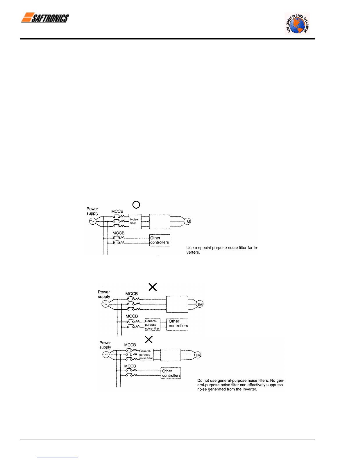
Chapter 3: Wiring
Installing an AC Reactor
If the Inverter is connected to a large capacity power transformer (600 kW or more) or the Power Factor Correction
Capacitor is switched, an excessive peak current may flow through the input power circuit, causing the converter unit
to break down.
To prevent this, install an optional AC Reactor on the input side of the Inverter or a DC reactor to the DC reactor
connection terminals.
This also improves the power factor on the power supply side.
Installing a Surge Absorber
Always use a surge absorber or diode for inductive loads near the Inverter. These inductive loads include Magnetic
Contactors, electromagnetic relays, solenoid valves, solenoids, and magnetic brakes.
Wiring the Power Terminals of Inverters with 18.5 to 300 kW Outputs
• For 200 V class Inverters of 18.5 to 75 kW or 400 V class Inverters of 18.5 to 45 kW, connect the r and s
terminals to the R and S terminals respectively. (These are shorted by a short-circuit bar for shipping.)
• For 400 V class, 55 to 300 kW, connect the r and s 400 terminals to the R and S terminals respectively. (These
are shorted by a short-circuit bar for shipping.)
Installing a Noise Filter on Power Supply Side
Install a noise filter to eliminate noise transmitted between the power line and the Inverter.
• Wiring Example 1
Figure 3.8 Correct Power Supply Noise Filter Installation
• Wiring Example 2
Figure 3.9 Incorrect Power Supply Noise Filter Installation
Firmware – S1043
Revision: 2 (9/98) 34 © Saftronics, Inc.

Chapter 3: Wiring
§ Wiring on the Output Side of Main Circuit
Connecting the Inverter and Motor
Connect output Terminals T1, T2, and T3 (U, V and W) to motor lead wires T1, T2, and T3, respectively.
Check that the motor rotates forward with the forward RUN command. Switch over any two of the output terminals to
each other and reconnect if the motor rotates in reverse with the forward RUN command.
Never Connect a Power Supply to Output Terminals
Never connect a power supply to output Terminals T1, T2, and T3 (U, V and W). If voltage is applied to the output
terminals, the internal circuits of the Inverter will be damaged.
Never Short or Ground Output Terminals
If the output terminals are touched with bare hands or the output wires come into contact with the Inverter casing, an
electric shock or grounding will occur. This is extremely hazardous. Do not short the output wires.
Do Not Use a Power Factor Correction Capacitor or Noise Filter
Never connect a Power Factor Correction Capacitor or LC/RC noise filter to an output circuit. Doing so may result in
damage to the Inverter or cause other parts to burn.
Do Not Use an Electromagnetic Switch or Magnetic Contactor
Do not connect an electromagnetic switch or Magnetic Contactor to an output circuit. If a load is connected to the
Inverter during operation, a surge current will actuate the overcurrent protective circuit in the Inverter.
Installing a Thermal Overload Relay
This Inverter has an electronic thermal protection function to protect the motor from overheating. If, however, more
than one motor is operated with one Inverter or a multi-polar motor is used, always install a Thermal Overload Relay
between the Inverter and the motor and set L1-01 to 0 (no motor protection).
Set the Thermal Overload Relay to the value on the motor nameplate when operating at 40 Hz and to 1.1 times the
value on the nameplate when operating at 60 Hz. The sequence should be designed so that the contacts of the
Thermal Overload Relay turn OFF the Magnetic Contactor on the main circuit inputs.
Installing a Noise Filter on Output Side
Connect a noise filter to the output side of the Inverter to reduce radio noise and inductive noise.
Inductive Noise: Electromagnetic induction generates noise on the signal line, causing the controller to
Radio Noise: Electromagnetic waves from the Inverter and cables cause the broadcasting radio receiver to
Countermeasures Against Inductive Noise
As described previously, a noise filter can be used to prevent inductive noise from being generated on the output
side. Alternatively, cables can be routed through a grounded metal pipe to prevent inductive noise. Keeping the
metal pipe at least 30 cm away from the signal line considerably reduces inductive noise.
Firmware – S1043
Revision: 2 (9/98) 35 © Saftronics, Inc.
malfunction.
make noise.
Figure 3.10 Installing a Noise Filter on the Output Side
Figure 3.11 Countermeasures Against Inductive Noise

Chapter 3: Wiring
Countermeasures Against Radio Interference
Radio noise is generated from the Inverter as well as from the input and output lines. To reduce noise, install noise
filters on both input and output sides, and also install the Inverter in a totally enclosed steel box.
The cable between the Inverter and the motor should be as short as possible.
Figure 3.12 Countermeasures Against Radio Interference
Cable Length Between Inverter and Motor
Steel box Metal Conduit
If the cable between the Inverter and the motor is long, the high-frequency leakage current will increase, causing the
Inverter output current to increase as well. This may affect peripheral devices. To prevent this, adjust the carrier
frequency (set in C6-01 to C6-03) as shown in Table 3.6. (For details, refer to the user constant settings.)
Table 3.6 Cable Length between Inverter and Motor
Cable Length 50 m max 100 m max. More than 100 m
Carrier Frequency 15 kHz max. 10 kHz max 5 kHz max.
(Set value: C6-01) (15.0) (10.0) (5.0)
(Set value: C6-02) (15.0) (10.0) (5.0)
(Set value: C6-03) (0) (0) (0)
§ Ground Wiring
• Always use the ground terminal of the 200 V Inverter with a ground resistance of less than 100 Ω and that of the
400 V Inverter with a ground resistance of less than 10 Ω.
• Do not share the ground wire with other devices, such as welding machines or power tools.
• Always use a ground wire that complies with technical standards on electrical equipment and minimize the
length of the ground wire.
Leakage current flows through the Inverter. Therefore, if the distance between the ground electrode and the
ground terminal is too long, potential on the ground terminal of the Inverter will become unstable.
• When using more than one Inverter, be careful not to loop the ground wire.
Firmware – S1043
Revision: 2 (9/98) 36 © Saftronics, Inc.
Figure 3.13 Ground Wiring

Chapter 3: Wiring
§ Connecting the Braking Resistor (ERF)
Connect the braking resistor as shown in Figure 3.14. When using a Braking Resistor Unit, set L8-01 to “1” (protect
selection for DB resistor) and set L3-04 to “0” (no Stall Prevention during deceleration).
Figure 3.14 Connecting the Braking Resistor
§ Connecting the Braking Resistor Unit and Braking Unit
Connect the Braking Resistor Unit and Braking Unit to the Inverter as shown in Figure 3.15. Set L8-01 to “0” (protect
selection for DB resistor) and L3-04 to “0” (no Stall Prevention during deceleration) before using the Inverter with the
Braking Resistor Unit connected.
Set L8-01 to “1” before operating the Inverter with the braking resistor without Thermal Overload Relay trip contacts.
The Braking Resistor Unit cannot be used and the deceleration time cannot be shortened by the Inverter if L3-04 is
set to “1” (i.e., if Stall Prevention is enabled for deceleration).
To prevent the unit from overheating, design the sequence to turn OFF the power supply for the Thermal Overload
Relay trip contacts of the Unit as shown in Figure 3.15.
200 V Class Inverters with 3.7 to 7.5 kW Output and
400 V Class Inverters with 3.7 to 15 kW Output
200 V Class Inverters with 11 kW or higher Output and
400 V Class Inverters with 18.5 kW or higher Output
Figure 3.15 Connecting the Braking Resistor Unit and Braking Unit
Firmware – S1043
Revision: 2 (9/98) 37 © Saftronics, Inc.

Chapter 3: Wiring
Connecting Braking Units in Parallel
When connecting two or more Braking Units in parallel, use the wiring and connectors shown in Figure
3.16. There are connectors for selecting whether each Braking Unit is to be a Master or Slave. Select
“Master” for the first Braking Unit only, and select “Slave” for all other Braking Units (i.e., from the second
Unit onwards).
Figure 3.16 Connecting Braking Units in Parallel
Power Supply Sequence
* Use a transformer with 200 and 400 V outputs for the power supply of the 400 V Inverter
Firmware – S1043
Revision: 2 (9/98) 38 © Saftronics, Inc.
Figure 3.17 Power Supply Sequence

3.5 Wiring Control Circuit Terminals
A control signal line must not be longer than 50 meters (164 feet) and must be separated from power lines. The frequency
reference must be input to the Inverter through twisted-pair wires.
3.5.1 Wire Sizes and Closed-Loop Connectors
Terminal numbers and wire sizes are shown in Table 3.7.
Table 3.7 Terminal Numbers and Wire Sizes (Same for all Models)
Terminals Terminal Screws AWG Sizes Wire Thickness (mm2) Wire Type
1 to 11, 13 to 33 M3.5 20-16
Stranded wire: 0.5 to 1.25
Single wire: 0.5 to 1.25
Chapter 3: Wiring
• Shielded, twisted-pair wire
12 (G) M3.5 20-14 0.5 to 2
The closed-loop connectors and tightening torques for various wire sizes are shown in Table 3.8.
Table 3.8 Closed-Loop Connectors for Ground Terminal
Terminals Terminal Screws Crimp Size Tightening Torque (n - m)
0.5 1.25 to 3.5
0.75 1.25 to 3.5
1.25 1.25 to 3.
2
M3.5
2 to 3.5
• Shielded, polyethylene-
covered, vinyl sheath cable
0.8
Firmware – S1043
Revision: 2 (9/98) 39 © Saftronics, Inc.

Chapter 3: Wiring
3.5.2 Control Circuit Terminal Functions
The functions of the control circuit terminals are shown in Table 3.9. Use the appropriate terminals for the correct
purposes.
Table 3.9 Control Circuit Terminals
Type No. Signal Name Function Signal Level
Forward run/stop command Forward run when CLOSED; stopped when OPEN.
1
Reverse run/stop command Reverse run when CLOSED; stopped when OPEN.
2
External fault input
3
Fault Reset Reset when CLOSED.
4
Sequence
input
Multi-step speed reference 1
5
(Master/auxiliary switch)
signals
Multi-step speed reference 2
6
Jog frequency reference Jog run when CLOSED.
7
External baseblock
8
Sequence input common
11
15 V power output 15 V power supply for analog reference
15
33 − 15 V power output − 15 V power supply for analog references
Master speed frequence
Analog
input
13
reference
signals
Multi-function analog input
16
Control common
17
Shield wire, optional ground
12
line connection point
9
Running signal (1 NO contact) Operating when CLOSED
10
Zero Speed detection
25
Sequence
output
signals
Speed agree detection
26
Open-collector output
27
common
18
19
Fault output signal (SPDT)
20
Frequency output 0 to 10 V/100% frequency
21
Analog
output
22
Common
signals
Current monitor 5 V/Inverter’s rated current
23
* When driving an inductive load, such as a relay coil, always insert a flywheel diode as shown in Figure 3.18.
Fault when CLOSED;
normal when OPEN
Auxiliary frequency
reference when
CLOSED.
Multi-step Setting 2
when CLOSED.
Inverter output stopped
when CLOSED.
− 10 to 10 V/−100% to 100%
0 to 10 V/100%
4 to 20 mA/100%, −10 to +10 V/−100% to 100%
0 to +10 V/100%
− 10 to 10 V/−100% to
100%
0 to 10 V/100%
Zero level (b2-01) or below
when CLOSED
Within ±2 Hz of set
frequency when CLOSED
Fault when CLOSED across 18 and 20
Fault when OPEN across 19 and 20
Multi-function contact inputs
(Command signals can be
selected by Setting H1-01 to
H1-06.)
−
Auxiliary analog input (H3-05)
− −
− −
Multi-function outputs
−
Multi-function analog
monitor 1
(H4-01, H4-02)
−
Multi-function analog
monitor 2
(H4-04m H4-05)
24 VDC, 8 mA Photocoupler
isolation
15 V
(Maximum current: 20 mA)
− 15 V
(Maximum current: 20 mA)
−10 to 10 V (20 kΩ),
0 to 10 V (20 kΩ)
4 to 20 mA (250 Ω)
−10 to 10 V (20 kΩ),
0 to 10 V (20 kΩ)
Dry contacts
Contact capacity:
1 A maximum at 250 VAC
1 A maximum at 30 VDC
Open-collector output
50 mA maximum at 48 V*
Dry contacts
Contact capacity:
1 A maximum at 250 VAC
1 A maximum at 30 VDC
0 to ±10 V maximum ±5%
2 mA maximum
Figure 3.18 Flywheel Diode Connection
Firmware – S1043
Revision: 2 (9/98) 40 © Saftronics, Inc.

11 12(G) 13 14 15 16 17 25 26 27 33 18 19 20
1 2 3 4 5 6 7 8 21 22 23 9 10
Figure 3.19 Control Circuit Terminal Arrangement
3.5.3 Control Circuit Terminal Connections (All Models)
Connections to VG5 control circuit terminals are shown in Figure 3.20.
Chapter 3: Wiring
Factory presets are shown in parentheses. When driving an inductive load, such as a relay coil, always insert a flywheel
diode as shown in Figure 3.18.
Firmware – S1043
Revision: 2 (9/98) 41 © Saftronics, Inc.
Figure 3.20 Control Circuit Terminal Connections

Chapter 3: Wiring
3.5.4 Control Circuit Wiring Precautions
• Separate control circuit wiring (Terminals 1 to 33) from main circuit wiring (Terminals L1, L2, and L3 (R, and S,
• Separate wiring for control circuit Terminals 9, 10, 18, 19, and 20 (contact outputs) from wiring for Terminals 1 to
• Use twisted-pair or shielded twisted-pair cables for control circuits to prevent operating faults. Process cable ends
• Connect the shield wire to Terminal 12(G).
• Insulate the shield with tape to prevent contact with other signal lines and equipment.
and T), B1, B2 , T1, T2, and T3 (U, V, and W), √, ⊕ 1, ⊕ 2, and ⊕ 3 and other high-power lines.
8, 21, 22, 23, 25, 26, 27, 33 and 11 to 17.
as shown in Figure 3.21.
Connect to shield
sheath terminal at
VG5 (Terminal 12)
Figure 3.21 Processing the Ends of Twisted-Pair Cables
3.6 Wiring Check
Check all of the wiring after wiring has been completed. Do not perform a megger check on control circuits.
• Is all wiring correct?
• Have any wire clippings, screws, or other foreign material been left?
• Are all screws tight?
• Are any wire ends contacting other terminals?
Firmware – S1043
Revision: 2 (9/98) 42 © Saftronics, Inc.

3.7 Installing and Wiring PG Speed Option Cards
PG Speed Option Cards are used for executing Speed Control using a PG. There are four types of PG Speed Controls, as shown
below. Select the type that fits the application and control method.
Part No.
PG-A2 031-4005 A-Phase (single) pulse input for open collector output or complementary outputs, for V/f Control
PG-B2 031-4006 A/B-Phase pulse input for open collector output or complementary outputs, for Vector Control
PG-D2 031-4007 A-Phase (single) pulse input for line driver input, for V/f Control
PG-X2 E001063-28 A/B/Z-Phase pulse input for line driver input, for Vector Control
3.7.1 Installing a PG Speed Option Card
Use the following procedure to install a PG Speed Option Card:
1. Turn OFF the main-circuit power supply.
2. Leave it OFF for at least one minute before removing the front cover of the Inverter (or at least three minutes for
Inverters of 30 kW or more). Check to be sure that the CHARGE indicator is OFF.
3. Insert the spacer (which is provided) into the spacer hole in the Inverter’s mounting base.
For Inverters of 3.7 kW or lower, there are two adjacent holes. Insert the spacer into the 7CN hole. The spacer
cannot be easily removed if inserted into the wrong hole. Be very careful to insert the spacer into the correct hole,
and in the proper direction.
4. Referring to the enlarged illustration in the following diagram, align the PG Speed Option Card with the catch position
as shown by (a) and (b) and fit it precisely to the Option-A connector. Insert (a) first.
5. Pass the spacer through the spacer hole at the card. (Refer to A in the illustration.) Check to be sure that it is
precisely aligned with the 4CN position, and snap it into the proper position. Be sure to press it in firmly until you
hear it snap into place.
Chapter 3: Wiring
Firmware – S1043
Revision: 2 (9/98) 43 © Saftronics, Inc.
Figure 3.22 Installing a PG Speed Option Card

Chapter 3: Wiring
3.7.2 PG Speed Option Card Terminal Blocks
The terminal specifications for each PG Speed Option Card are given in the following tables:
§ PG-A2 (For V/f with PG Feedback Mode Only)
§ PG-B2 (For Flux Vector Control Mode Only)
Table 3.10 PG-A2 Terminal Specifications
Terminal No. Contents Specifications
1
Power Supply for pulse generator
2
3
TA1
TA2 (E) Shield connection terminal
Terminal No. Contents Specifications
TA1
TA2
TA3 (E) Shield connection terminal
4
5
6
7
8
1
2
3
4
5
6
1 Open collector output, 24 VDC, 30 mA maximum
2
3 Open collector output, 24 VDC, 30 mA maximum
4
+12 V/open collector switching
terminal
Pulse input terminal
Pulse motor output terminal
Table 3.11 PG-B2 Terminal Specifications
Power Supply for pulse generator
A-Phase pulse input terminal
B-Phase pulse input terminal
A-Phase monitor output terminal
B-Phase monitor output terminal
12 VDC(±5%), 200 mA maximum
0 VDC (GND for power supply)
Terminal for switching between 12 V voltage
input and open collector input. For open collector
input, short across 3 and 4
H: +4 to 12 V; L: +1 V maximum. (maximum
response frequency: 30 kHz)
Pulse input common
12 VDC (+10%), 20 mA maximum
Pulse monitor output common
12 VDC(±5%), 200 mA maximum
0 VDC (GND for power supply)
H: +8 to 12 V
L: +1 V maximum
(maximum response frequency: 30 kHz)
Pulse input common
H: +8 to 12 V
L: +1 V maximum
(maximum response frequency: 30 kHz)
Pulse input common
A-Phase monitor output common
B-Phase monitor output common
§ PG-D2 (For V/f with PG Feedback Mode Only)
Table 3.12 PG-D2 Terminal Specifications
Terminal No. Contents Specifications
TA1
TA2 (E) Shield connection terminal —
NOTE: 5 VDC and 12 VDC cannot be used at the same time.
Firmware – S1043
Revision: 2 (9/98) 44 © Saftronics, Inc.
1
2 0 VDC (GND for power supply)
3
4
5
6 Common terminal —
7
8
Power Supply for pulse generator
Pulse input + terminal
Pulse input − terminal
Pulse monitor output + terminal
Pulse monitor output − terminal
12 VDC(±5%), 200 mA maximum (see note)
5 VDC ((±5%), 200 mA maximum (see note)
Line driver input (RS-422 level input)
Maximum response frequency: 300 kHz
Line driver output (RS-422 level output)

§ PG-X2 (For Flux Vector Control Mode Only)
Table 3.13 PG-X2 Terminal Specifications
Terminal No. Contents Specifications
1
2 0 VDC (GND for power supply)
Power Supply for pulse generator
3
4
A-Phase + input terminal
5
TA1
10 Common terminal 0 VDC (GND for power supply)
TA2
TA3 (E) Shield connection terminal —
NOTE: 5 VDC and 12 VDC cannot be used at the same time.
3.7.3 Wiring a PG Speed Option Card
Wiring examples are provided in the following illustrations for the PG Speed Option Cards.
A-Phase − input terminal
6
B-Phase + input terminal
7
B-Phase − input terminal
8
Z-Phase + input terminal
9
Z-Phase − input terminal
1
A-Phase + output terminal
2
A-Phase − output terminal
3
B-Phase + output terminal
4
B-Phase − output terminal
5
Z-Phase + input terminal
6
Z-Phase − input terminal
7 Control circuit common Control circuit GND
Chapter 3: Wiring
12 VDC(±5%), 200 mA maximum (see note)
5 VDC ((±5%), 200 mA maximum (see note)
Line driver input (RS-422 level input)
(maximum response frequency: 300 kHz)
Line driver output (RS-422 level output)
§ PG-A2 (For V/f with PG Feedback Mode Only)
12 V Voltage Input
Figure 3.23 Wiring a 12 V Voltage Input
Firmware – S1043
Revision: 2 (9/98) 45 © Saftronics, Inc.

Chapter 3: Wiring
Open Collector Input
• Shielded twisted-pair wires must be used for signal lines.
• Do not use the PG’s power supply for anything other than the PG. Using it for another
purpose can cause malfunctions due to noise.
• The length of the PG’s wiring must not be more than 100 meters (328 feet).
Figure 3.24 Wiring an Open-Collector Input
I/O Circuit Configuration
Figure 3.25 I/O Circuit Configuration of the PG-A2
Firmware – S1043
Revision: 2 (9/98) 46 © Saftronics, Inc.

§ PG-B2 (For Flux Vector Control Mode Only)
• Shielded twisted-pair wires must be used for signal lines.
• Do not use the PG’s power supply for anything other than the PG. Using it for another
purpose can cause malfunctions due to noise.
• The length of the PG’s wiring must not be more than 100 meters (328 feet).
• The direction of rotation of the Inverter can be set in user constant F1-05. The factory preset
if for forward rotation, A-Phase advancement.
Figure 3.26 PG-B2 Wiring
I/O Circuit Configuration
Chapter 3: Wiring
• When connecting to a voltage-output-type PG, select a PG that has an
output impedance with a current of at least 12 mA to the input circuit
photocoupler (diode).
Firmware – S1043
Revision: 2 (9/98) 47 © Saftronics, Inc.
Figure 3.27 I/O Circuit Configuration of the PG-B2

Chapter 3: Wiring
§ PG-D2 (For V/f with PG Feedback Mode Only)
• Shielded twisted-pair wires must be used for signal lines.
• Do not use the PG’s power supply for anything other than the PG. Using it for another
purpose can cause malfunctions due to noise.
• The length of the PG’s wiring must not be more than 100 meters (328 feet).
Figure 3.28 PG-D2 Wiring
§ PG-X2 (For Flux Vector Control Mode Only)
• Shielded twisted-pair wires must be used for signal lines.
• Do not use the PG’s power supply for anything other than the PG. Using it for another
purpose can cause malfunctions due to noise.
• The length of the PG’s wiring must not be more than 100 meters (328 feet).
• The direction of rotation of the Inverter can be set in user constant F1-05. The factory preset
if for forward rotation, A-Phase advancement.
Firmware – S1043
Revision: 2 (9/98) 48 © Saftronics, Inc.
Figure 3.29 PG-X2 Wiring

3.7.4 Wiring PG Speed Option Card Terminal Blocks
Use no more than 100 meters (328 feet) of wiring for PG signal lines, and keep them separate from power lines.
Use shielded, twisted-pair wires for pulse inputs and pulse output monitor wires, and connect the shield to the shield
connection terminal.
§ Wire Sizes (Same for All Models)
Terminal wire sizes are shown in Table 3.14.
Table 3.14 Wire Sizes
Terminal
PG power supply
Pulse input terminal
Pulse monitor output terminal
Shield connection terminal M3.5 0.5 to 2 20-14
Terminal
Screws
Wire Thickness (mm2) AWG Sizes Wire Type
Stranded wire: 0.5 to 1.25
Single wire: 0.5 to 1.25
§ Solderless Terminals for Control Circuit Terminals
The use of solderless terminals for the control circuit terminals is recommended because solderless terminals are
easy to connect securely.
Table 3.15 Straight Solderless Terminal Sizes
Wire Thickness
(mm2)
0.5 20 A1 0.5-8 WH 1.00 2.60
0.75 18 A1 0.75-8 GY 1.20 2.80
1 16 A1 1-8 RD 1.40 3.00
1.5 14 A1 1.5-8 BK 1.70 3.50
AWG Sizes Model d1 d2 Manufacturer
20-16
Chapter 3: Wiring
• Shielded, twisted-pair
wire
• Shielded, polyethylene-
covered, vinyl sheath
cable
Phoenix Contact
NOTE: Do not solder wires with the control circuit terminal if wires are used instead of solderless terminals. Wires many not contact
well with the control circuit terminals or the wires may be disconnected from the control circuit terminals due to oscillation if the
wires are soldered.
Firmware – S1043
Revision: 2 (9/98) 49 © Saftronics, Inc.
Figure 3.30 Straight Solderless Terminal Sizes

Chapter 3: Wiring
§ Closed-Loop Connector Sizes and Tightening Torque
The closed-loop connectors and tightening torques for various wire sizes are shown in Table 3.16.
Table 3.16 Closed-Loop Connectors and Tightening Torques
Wire Thickness
(mm2)
0.5 20 1.25 to 3.5
0.75 18 1.25 to 3.5
1.25 16 1.25 to 3.5
2 14
AWG Sizes Terminal Screws
M3.5
Crimp Terminal
Size (mm2)
2 to 3.5
§ Wiring Method
Use the following procedure to connect wires to the terminal block:
1. Loosen the terminal screws with a thin-slot screwdriver.
2. Insert the wires from underneath the terminal block.
3. Tighten the terminal screws firmly.
Tightening Torque
(N · m)
0.8
NOTE: Wiring Precautions
1. Separate PG Speed Option Card control circuit wiring (Terminals TA1 and TA2) from main circuit wiring and other highpower lines.
2. Use twisted-pair or shielded twisted-pair cables to connect the PG to prevent operating faults. Process cable ends as
shown in Figure 3.32. The maximum cable length is 100 meters (328 feet).
Connect to terminal
TA3 on the VG5.
3. Connect the shield to the ground terminal.
4. Do not solder the wires to the control circuit terminals. The wires may not contact well with the control circuit terminals
if the wires are soldered.
5. The end of each wire connected to the control circuit terminals must be stripped for approximately 5.5 mm (0.22
inches).
Figure 3.31 Connecting Wires to Terminal Block
Figure 3.3 Processing the Ends of Twisted-pair Cables
Firmware – S1043
Revision: 2 (9/98) 50 © Saftronics, Inc.

3.7.5 Selecting the Number of PG Pulses
§ PG-A2/PG-B2
The maximum response frequency is 32,767 Hz. Use a PG that outputs a maximum frequency of approximately 20
kHz for the rotational speed of the motor.
Motor speed at maximum frequency output (r/min)
60
Some examples of PG output frequency (number of pulses) for the maximum frequency output are shown in Table
3.17.
Table 3.17 PG Pulse Selection Examples
Motor’s Maximum Speed (r/min) PG Rating (p/rev)
1800 600 18,000
1500 800 20,000
1200 1000 20,000
900 1200 18,000
NOTE: 1. The motor speed at maximum frequency output is expressed as the sync rotation speed.
2. The PG power supply is 12 V.
3. A separate power supply is required if the PG power supply capacity is greater than 200 mA. (If
momentary power loss must be handled, use a backup capacitor or other method.)
Chapter 3: Wiring
X PG rating (p/rev) = 20,000 Hz
PG Output Frequency for Maximum
Frequency Output (Hz)
§ PG-D2/PG-X2
The maximum response frequency is 300 kHz.
Use the following equation to compute the output frequency of the PG (fPG):
f
(Hz) =
PG
A separate power supply is required if the PG power supply capacity is greater than 200 mA. (If momentary power
loss must be handled, use a backup capacitor or other method.)
Firmware – S1043
Revision: 2 (9/98) 51 © Saftronics, Inc.
Figure 3.33 PG-B2 Connection Example
Motor speed at maximum frequency output (r/min)
60
X PG rating (p/rev)

Chapter 3: Wiring
Figure 3.34 PG-X2 Connection Example
Firmware – S1043
Revision: 2 (9/98) 52 © Saftronics, Inc.
 Loading...