


FP5/GP5
efesotomasyon.com - Control Techniques,emerson,saftronics -ac drive-servo motor
TECHNICAL MANUAL

efesotomasyon.com - Control Techniques,emerson,saftronics -ac drive-servo motor

PREFACE
•
•
•
efesotomasyon.com - Control Techniques,emerson,saftronics -ac drive-servo motor
Saftronics’ FP5/GP5 is the world’s first optimized Inverter specifically designed for general-purpose applications. This manual describes
installation, maintenance and inspection, troubleshooting, and specifications of the FP5/GP5. Read this manual thoroughly before operation.
General Precautions
Some drawings in this manual are shown with the protective cover or shields removed, in
order to describe detail with more clarity. Make sure all covers and shields are replaced
before operating this product.
This manual may be modified when necessary because of improvement of the product,
modification, or changes in specifications. Such modifications are denoted by a revision
number.
• To order a copy of this manual, contact your Saftronics representative.
Saftronics is not responsible for any modification of the product made by the user, since that
will void your warranty.
PREFACE
•
efesotomasyon.com - Control Techniques,emerson,saftronics -ac drive-servo motor
Notes for Safe Operation
Read this manual thoroughly before installation, operation, maintenance or inspection of the FP5/GP5. In this manual, notes for safe
operation are classified as followed:
WARNING
CAUTION
Even items described in CAUTION may result in a fatal accident in some situations. In either case, follow these important notes.
Take the following steps to ensure proper operation.
Indicates a potentially hazardous situation which, if not avoided, could result in death or serious injury
to personnel.
Indicates a potentially hazardous situation which, if not avoided, may result in minor or moderate injury
to personnel and damage to equipment. It may also be used to alert against unsafe practices.
§ Receiving
CAUTION
Do not install or operate any Inverter that is damaged or has missing parts. Failure to observe this may
result in personal injury or equipment damage.
§ Installation
CAUTION
• When moving the unit, lift the cabinet by the base, never lift by the front cover. Otherwise, the main unit
may be dropped causing damage to the unit.
• Mount the Inverter on nonflammable material (i.e., metal). Failure to observe this can result in a fire.
• When mounting units in an enclosure, install a fan or other cooling device to keep the intake air
temperature below 45°C. Overheating may cause a fire or damage the unit.
Page
2
Page
6
6
6
§ Wiring
WARNING
• Only commence wiring after verifying that the power supply is turned OFF. Failure to observe this
warning can result in an electrical shock or fire.
• Wiring should be performed only by qualified personnel. Failure to observe this warning can result in an
electrical shock or fire.
• When wiring the emergency stop circuit, check the wiring thoroughly before operation. Failure to
observe this warning can result in personal injury.
• Make sure to ground the ground terminal ( ). (Ground resistance 200V class: 100Ω or less, 400V
class: 10Ω or less.) Failure to observe this warning can result in an electrical shock or fire.
Firmware – S2011 and S3012
Revision: 1 (9/98) ii © Saftronics, Inc.
Page
10
10
10
11

PREFACE
efesotomasyon.com - Control Techniques,emerson,saftronics -ac drive-servo motor
CAUTION
• Verify that the Inverter rated voltage coincides with the AC power supply voltage. Failure to observe this
can result in personal injury or fire.
• Do not perform a withstand voltage test on the Inverter. It may cause semi-conductor elements to be
damaged.
• To connect a Braking Resistor, Braking Resistor Unit or Braking Unit, follow the procedures described in
Chapter 11. Improper connection may cause a fire.
• Tighten terminal screws to the specified tightening torque. Failure to observe this can result in a fire.
• Never connect the AC main circuit power supply to output Terminals T1, T2, and T3 (U, V, and W). The
Inverter will be damaged and invalidate the warranty.
§ Operation
WARNING
• Only turn ON the input power supply after replacing the front cover. Do not remove the cover while
current is flowing. Failure to observe this can result in an electrical shock.
• When the retry function (n057) is selected, do not approach the Inverter or the load, since it may restart
suddenly after being stopped. (Construct machine system, so as to assure safety for personnel, even if
the Inverter should restart.) Failure to observe this can result in personal injury.
• Since the stop button can be disabled by a function setting, install a separate emergency stop switch.
Failure to observe this can result in personal injury.
Page
10
10
10
10
11
Page
24
24
24
CAUTION
• Never touch the heatsink or discharging resistor since the temperature is very high. Failure to observe
this can result in harmful burns to the body.
• Since it is easy to change operation speed from low to high speed, verify the safe working range of the
motor and machine before operation. Failure to observe this can result in personal injury and machine
damage.
• Install a holding brake separately, if necessary. Failure to observe this can result in personal injury.
• Do not change signals during operation. The machine or the Inverter may be damaged.
• All the constants of the Inverter have been preset at the factory. Do not change the settings
unnecessarily. The Inverter may be damaged. For supply voltage, follow Paragraph 4.3 of Chapter 4.
Page
24
24
24
24
24
Firmware – S2011 and S3012
Revision: 1 (9/98) iii © Saftronics, Inc.
PREFACE
•
efesotomasyon.com - Control Techniques,emerson,saftronics -ac drive-servo motor
§ Maintenance and Inspection
WARNING
• Never touch high-voltage terminals in the Inverter. Failure to observe this can result in an electrical
shock.
• Replace all protective covers before powering up the Inverter. To remove the cover, make sure to shut
OFF the Molded Case Circuit Breaker. Failure to observe this can result in an electrical shock.
• Perform maintenance or inspection only after verifying that the CHARGE LED goes OFF, after main
circuit power supply is turned OFF. The capacitors are still charged and can be dangerous.
• Only authorized personnel should be permitted to perform maintenance, inspections or parts
replacement. (Remove all metal objects (watches, bracelets, etc.) before operation. Use tools that are
insulated against electrical shock.) Failure to observe this can result in an electrical shock.
CAUTION
• The control PC board employs CMOS ICs. Do not touch the CMOS elements. They are easily damaged
by static electricity.
• Do not connect or disconnect wires or connectors while power is applied to the circuit. Failure to observe
this can result in personal injury.
Page
64
64
64
64
Page
64
64
§ Others
WARNING
Never modify the product. Failure to observe this can result in an electrical shock or personal injury and
will invalidate the warranty.
Firmware – S2011 and S3012
Revision: 1 (9/98) iv © Saftronics, Inc.

Table of Contents
efesotomasyon.com - Control Techniques,emerson,saftronics -ac drive-servo motor
1 Receiving .............................................................................................. 1
1.1 Inspection Checkpoints.................................................................................. 2
1.2 Identifying the Parts....................................................................................... 2
2 Installation ............................................................................................ 5
2.1 Removing and Replacing the Digital Operator................................................ 6
2.2 Removing and Replacing the Front Cover...................................................... 7
2.3 Choosing a Location to Mount the Inverter..................................................... 7
2.4 Clearances .................................................................................................... 8
3 Wiring .................................................................................................... 9
3.1 Connection Diagram...................................................................................... 10
1.1.1 Receiving Checkpoints........................................................................................................ 2
1.1.2 Checking the Nameplate Data............................................................................................ 2
2.1.1 Removing the Digital Operator .......................................................................................... 6
2.1.2 Replacing the Digital Operator............................................................................................ 6
3.2 Wiring the Main Circuit................................................................................... 11
3.2.1 Wiring Precautions for Main Circuit Point ........................................................................... 11
3.2.2 Wiring Precautions for Main Circuit Output........................................................................ 12
3.2.3 Grounding............................................................................................................................ 12
3.2.4 Functions of Main Circuit Terminals................................................................................... 13
3.2.5 Main Circuit Configuration................................................................................................... 15
3.2.6 Parts Required for Wiring.................................................................................................... 17
3.3 Wiring the Control Circuit............................................................................... 21
3.3.1 Functions of Control Circuit Terminals ............................................................................... 21
3.3.2 Wiring the Control Circuit Terminals................................................................................... 22
3.3.3 Precautions on Control Circuit Wiring................................................................................. 22
3.4 Wiring Inspection........................................................................................... 22
4 Operation .......................................................................................... 23
4.1 Operation Mode Selection.............................................................................. 25
4.2 Test Run Checkpoints.................................................................................... 26
4.3 Setting the Line Voltage Using Jumper (For 400V Class 18.5kW and Above). 26
4.4 Test Run........................................................................................................ 27
4.4.1 Digital Operator Display at Power-Up................................................................................. 27
4.4.2 Operation Check Points...................................................................................................... 28
4.4.3 Example of Basic Operation ............................................................................................... 28
5 Simple Data Setting.............................................................................. 31
5.1 Digital Operator Key Description.................................................................... 32
5.2 LED Description............................................................................................. 32
6 Programming Features ........................................................................ 35
6.1 Constant Set-Up and Initialization.................................................................. 36
6.1.1 Constant Selection/Initialization (n001).............................................................................. 36
6.2 V/f Pattern Setting.......................................................................................... 36
6.2.1 Preset V/f Pattern................................................................................................................ 37
6.2.2 Custom V/f Pattern.............................................................................................................. 38
6.3 Setting Operation Conditions ......................................................................... 38
Firmware – S2011 and S3012
Revision: 1 (9/98) v © Saftronics, Inc.
6.3.1 Reverse Run Prohibit (n006) .............................................................................................. 38
6.3.2 Multi-Step Speed Selection................................................................................................. 38
6.3.3 Operation at Low Speed ..................................................................................................... 39
6.3.4 Adjusting Frequency Setting Signal.................................................................................... 40
6.3.5 Adjusting Frequency Upper and Lower Limits ................................................................... 41

6.3.6 Using Two Accel/Decel Times............................................................................................ 41
efesotomasyon.com - Control Techniques,emerson,saftronics -ac drive-servo motor
6.3.7 Automatic Restart after Momentary Power Loss (n051) ................................................... 42
6.3.8 Soft-Start Characteristics (n023)........................................................................................ 42
6.3.9 Torque Detection................................................................................................................. 43
6.3.10 Frequency Detection (n073)............................................................................................... 44
6.3.11 Jump Frequencies (n058 to n060) ..................................................................................... 44
6.3.12 Continuing Operation by Automatic Fault Reset (n056).................................................... 45
6.3.13 Operating Coasting Motor without Trip .............................................................................. 45
6.3.14 Using Frequency Meter of Ammeter (n048)....................................................................... 46
6.3.15 Calibrating Frequency Meter of Ammeter (n049) .............................................................. 46
6.3.16 Reducing Motor Noise or Leakage Current (n050)............................................................ 47
6.4 Selecting Stopping Method ............................................................................. 48
6.4.1 Selecting Stopping Method (n004)..................................................................................... 48
6.4.2 Coast to Stop with Timer 1 (n004=2) ................................................................................. 49
6.4.3 Applying DC Injection Braking Current (n064)................................................................... 49
6.5 Building Interface Circuits with External Devices............................................. 50
6.5.1 Using Sequence Input Signals (n035 to n039).................................................................. 50
6.5.2 Using Analog Input Signals (n042 to n045) ....................................................................... 53
6.5.3 Using Output Signals (n040, n041).................................................................................... 55
6.6 Setting Operation Conditions.......................................................................... 56
6.6.1 Torque Compensation Gain (n067).................................................................................... 56
6.7 Motor Protection ............................................................................................. 57
6.7.1 Motor Overload Detection................................................................................................... 57
6.8 PID Control .................................................................................................... 58
6.8.1 Intended Value Setting........................................................................................................ 58
6.8.2 Detected Value Setting....................................................................................................... 58
6.9 Energy Saving Control ................................................................................... 59
6.9.1 Energy Saving Gain K2 (n096)........................................................................................... 59
6.9.2 Energy Saving Tuning......................................................................................................... 59
6.10 MEMOBUS Control........................................................................................ 60
6.10.1 Communication Specifications ........................................................................................... 60
6.10.2 Data to be Sent/Received by Communication................................................................... 60
7 Maintenance and Inspection................................................................ 63
7.1 Periodic Inspector .......................................................................................... 64
7.2 Parts Replacement Schedule (Guidelines)...................................................... 64
8 Troubleshooting.................................................................................... 65
8.1 Fault Diagnosis and Corrective Actions .......................................................... 66
8.2 Alarm Display and Explanation....................................................................... 69
8.3 Motor Faults and Corrective Actions............................................................... 70
9 Specifications........................................................................................ 71
9.1 Standard Specifications .................................................................................. 72
10 Dimensions............................................................................................ 75
10.1 Dimensions .................................................................................................... 76
11 Typical Connection Diagram................................................................ 79
11.1 Braking Resistor Unit...................................................................................... 80
11.2 Braking Unit and Braking Resistor Unit........................................................... 81
12 Constant List .........................................................................................83
12.1 Constant List.................................................................................................. 84
13 Digital Operator Monitor Display ......................................................... 91
13.1 Digital Operator Monitor Display..................................................................... 92
INDEX................................................................................................................ 95
Firmware – S2011 and S3012
Revision: 1 (9/98) vi © Saftronics, Inc.

1
efesotomasyon.com - Control Techniques,emerson,saftronics -ac drive-servo motor
Receiving
This chapter describes how to inspect the inverter after delivery to the user.
1.1 Inspection Checkpoints.................................................. 2
1.1.1 Receiving Checkpoints....................................................................................... 2
1.1.2 Checking the Nameplate Data ........................................................................... 2
1.2 Identifying the Parts........................................................ 2

Chapter 1: Receiving
•
efesotomasyon.com - Control Techniques,emerson,saftronics -ac drive-servo motor
CAUTION
Do not install or operate any Inverter which is damaged or has missing parts. Failure to observe this may result in personal injury or
equipment damage.
1.1 Inspections Checkpoints
1.1.1 Receiving Checkpoints
Table 1 Checkpoints
Does the Inverter model number correspond with the purchase
order?
Are any parts damaged?
Is hardware properly seated and securely tightened?
Was an instruction manual received? FP5/GP5 Instruction Manual
If any of the above checkpoints are not satisfactory, contact your Saftronics representative.
1.1.2 Checking the Nameplate Data
§ Nameplate Data
Checkpoints Description
Check the model number on the nameplate on the side of the
FP5/GP5. (See below.)
Visually check the exterior and verify that there was no
damage during transport.
Remove Inverter front cover. Check all visible hardware with
appropriate tools.
§ Model Designation
Figure 1 Nameplate Data
Figure 2 Model Designation
Firmware – S2011 and S3012
Revision: 1 (9/98) 2 © Saftronics, Inc.

§ Specification Designation
efesotomasyon.com - Control Techniques,emerson,saftronics -ac drive-servo motor
∗ For special specifications, a spec sheet number appears on the nameplate.
1.2 Identifying the Parts
Chapter 1: Receiving
Figure 3 Specification Designation
Figure 4 Configuration of FP5/GP5
Firmware – S2011 and S3012
Revision: 1 (9/98) 3 © Saftronics, Inc.

Chapter 1: Receiving
efesotomasyon.com - Control Techniques,emerson,saftronics -ac drive-servo motor
NOTES:
Firmware – S2011 and S3012
Revision: 1 (9/98) 4 © Saftronics, Inc.

2
efesotomasyon.com - Control Techniques,emerson,saftronics -ac drive-servo motor
Installation
This chapter describes configuration, location and clearances when mounting the FP5/GP5.
2.1 Removing and Replacing the Digital Operator............. 6
2.1.1 Removing the Digital Operator........................................................................... 6
2.1.2 Replacing the Digital Operator........................................................................... 6
2.2 Removing and Replacing the Front Cover.................... 7
2.3 Choosing a Location to Mount the Inverter.................. 7
2.4 Clearances....................................................................... 8

Chapter 2: Installation
•
efesotomasyon.com - Control Techniques,emerson,saftronics -ac drive-servo motor
CAUTION
When moving the unit, lift the cabinet by the base, never lift by the front cover. Otherwise, the main unit may be dropped causing
damage to the unit.
• Mount the Inverter on nonflammable material, (i.e., metal). Failure to observe this can result in a fire.
• When mounting units in an enclosure, install a fan or other cooling device to keep the intake air temperature below 45°C. Overheating
may cause a fire or damage to the unit.
2.1 Removing and Replacing the Digital Operator
Remove and replace the Digital Operator as follows:
2.1.1 Removing the Digital Operator
To remove the Digital Operator from the front cover,
push the Digital Operator lever in the direction
shown by arrow 1 and lift the Digital Operator in the
direction shown by arrow 2.
Figure 5 Removing the Digital Operator
2.1.2 Replacing the Digital Operator
Engage the Digital Operator on claws A in the
direction shown by arrow 1 and then on claws B in
the direction shown by arrow 2 to lock the Digital
Operator.
Figure 6 Replacing the Digital Operator
NOTE: Never fit the Digital Operator in any other direction or by any other method. The Digital Operator will not be connected to the
Inverter.
Firmware – S2011 and S3012
Revision: 1 (9/98) 6 © Saftronics, Inc.
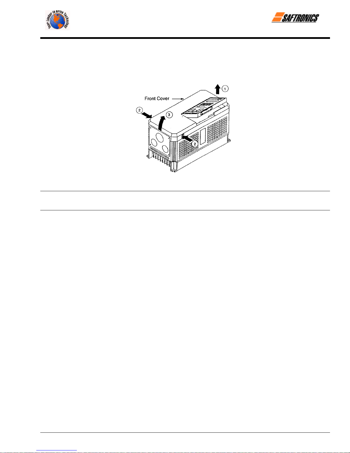
2.2 Removing and Replacing the Front Cover
efesotomasyon.com - Control Techniques,emerson,saftronics -ac drive-servo motor
To remove the front cover, first move the Digital Operator in the direction shown by arrow 1. (Figure 5). Then squeeze the cover in
the direction shown by arrows 2 on both sides and lift in the direction shown by arrow 3.
Figure 7 Removing and Replacing the Front Cover
Chapter 2: Installation
NOTE: Do not replace the front cover with the Digital Operator connected. The Digital Operator will not be connected to the Inverter.
Replace the front cover first and then install the Digital Operator on the cover. See Figure 6 for replacing the Digital Operator.
2.3 Choosing a Location to Mount the Inverter
To ensure proper performance and long operating life, follow the recommendations below when choosing a location for installing the
FP5/GP5. Make sure the Inverter is protected from the following conditions:
o Extreme cold and heat. Use only within ambient temperature range: −10°C to + 40°C.
o Rain, moisture. (For enclosed wall-mounted type.)
o Oil sprays, splashes.
o Salt spray.
o Direct sunlight. (Avoid using outdoors.)
o Corrosive gases or liquids.
o Dust or metallic particles in the air. (For enclosed wall-mounted type.)
o Physical shock, vibration.
o Magnetic noise. (Example: welding machines, power devices, etc.)
o High humidity.
o Radioactive materials.
o Combustibles: thinners, solvents, etc.
Firmware – S2011 and S3012
Revision: 1 (9/98) 7 © Saftronics, Inc.
Chapter 2: Installation
efesotomasyon.com - Control Techniques,emerson,saftronics -ac drive-servo motor
2.4 Clearances
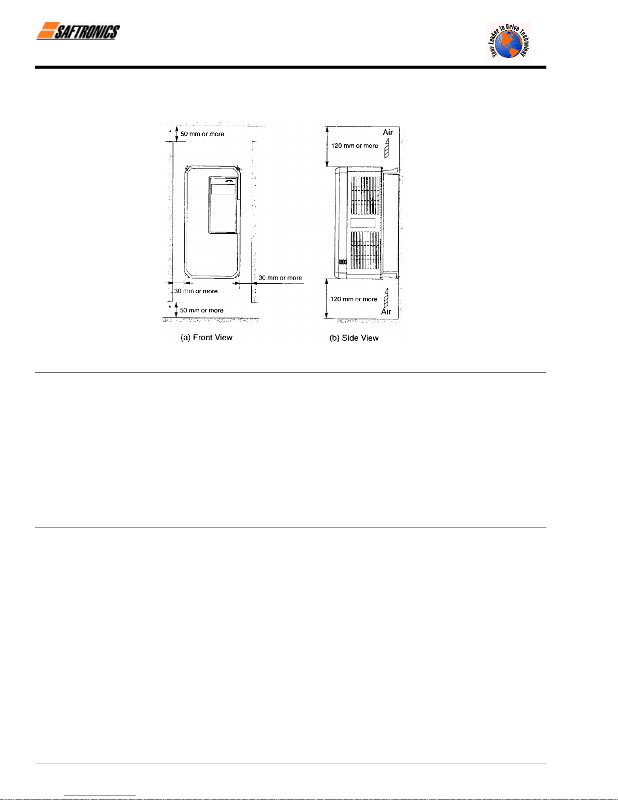
Install the FP5/GP5 vertically and allow sufficient clearances for effective cooling as shown below.
Figure 8 Clearances
NOTE: 1. The clearances required at the top and bottom and both sides are common in open chassis type (IP00) and enclosed
wall-mounted type (NEMA1/IP20).
2. Remove the top and bottom covers to use the open chassis type of 200V/400V 15kW or less.
3. When installing the models of 200V/400V 30kW or more equipped with eyebolts, extra spacing will be required on either
side. For detailed dimensions, contact your Saftronics representative.
4. For the external dimensions and mounting dimensions, refer to Chapter 10 Dimensions.
5. Allowable intake air temperature to the Inverter:
• Open chassis type (IP00) : - 10°C to 45°C
• Enclosed wall-mounted type : - 10°C to 40°C (NEMA 1/IP20)
6. Ensure sufficient space for the sections at the upper and lower parts marked with [ in order to permit the flow of
intake/exhaust air to/from the Inverter.
Firmware – S2011 and S3012
Revision: 1 (9/98) 8 © Saftronics, Inc.

3
efesotomasyon.com - Control Techniques,emerson,saftronics -ac drive-servo motor
Wiring
This chapter describes the main circuit wiring and the control circuit wiring of the FP5/GP5.
3.1 Connection Diagram....................................................... 10
3.2 Wiring the Main Circuit................................................... 11
3.2.1 Wiring Precautions for Main Circuit Input .......................................................... 11
3.2.2 Wiring Precautions for Main Circuit Output........................................................ 12
3.2.3 Grounding ........................................................................................................... 12
3.2.4 Functions of Main Circuit Terminals................................................................... 13
3.2.5 Main Circuit Configuration.................................................................................. 15
3.2.6 Parts Required for Wiring................................................................................... 17
3.3 Wiring the Control Circuit .............................................. 21
3.3.1 Functions of Control Circuit Terminals............................................................... 21
3.3.2 Wiring the Control Circuit Terminals.................................................................. 22
3.3.3 Precautions on Control Circuit Wiring................................................................ 22
3.4 Wiring Inspection............................................................ 22

Chapter 3: Wiring
•
•
•
efesotomasyon.com - Control Techniques,emerson,saftronics -ac drive-servo motor
WARNING
Only commence wiring after verifying that the power supply is turned OFF. Failure to observe this can result in an electrical shock or
fire.
• Wiring should be performed only by qualified personnel. Failure to observe this can result in an electrical shock or fire.
When wiring the emergency stop circuit, check the wiring thoroughly before operation. Failure to observe this can result in personal
injury.
CAUTION
• Verify that the Inverter rated voltage coincides with the AC power supply voltage. Failure to observe this can result in personal injury
or fire.
• Do not perform a withstand voltage test of the Inverter. It may cause semi-conductor elements to be damaged.
To connect a Braking Resistor, Braking Resistor Unit or Braking Unit, follow the procedures described in Chapter 11. Improper
connection may cause fire.
• Tighten terminal screws to the specified tightening torque. Failure to observe this can result in a fire.
3.1 Connection Diagram
Below is a connection diagram of the main circuit and control circuit. Using the Digital Operator, the motor can be operated by
wiring the main circuit only.
Figure 9 FP5/GP5 Connection Diagram
Firmware – S2011 and S3012
Revision: 1 (9/98) 10 © Saftronics, Inc.

Chapter 3: Wiring
•
•
efesotomasyon.com - Control Techniques,emerson,saftronics -ac drive-servo motor
NOTE:
1.
2. Voltage or current input for the master frequency reference can be selected by constant n042. Voltage reference input is
preset at the factory (FV).
3. Control circuit Terminal FS of + 15V has a maximum output current capacity of 20 mA.
4. Multi-function analog output should be used for monitoring meters (e.g., output frequency meter) and should not be used
for feedback control system.
3.2 Wiring the Main Circuit
Make sure to ground the ground terminal ( ). (Ground resistance 200V class: 100Ω or less, 400V class: 10× or less.)
Failure to observe this can result in an electrical shock or a fire.
Never connect the AC main circuit power supply to output Terminals T1, T2, and T3 (U, V and W). The Inverter will be
damaged and invalidate the warranty.
3.2.1 Wiring Precautions for Main Circuit Input
§ Installation of Molded Case Circuit Breaker (MCCB)
Make sure to connect Molded Case Circuit Breakers (MCCB) or fuses between AC main circuit power supply and
FP5/GP5 input Terminals L1, L2 and L3 (R, S, and T) to protect wiring.
P
indicates twisted-pair shielded wires.indicates shielded wires and
WARNING
CAUTION
§ Installation of Ground Fault Interrupter
When connecting a ground fault interrupter to input Terminals L1, L2 and L3 (R, S, and T), select one that is not
affected by high frequency.
Examples: NV series by Mitsubishi Electric Co., Ltd. (manufactured in or after 1988), EG, SG series by Fuji Electric
Co., Ltd. (manufactured in or after 1984).
§ Installation of Magnetic Contactor
Inverters can be used without a Magnetic Contactor (MC) installed at the power supply side. When the main circuit
power supply is shut OFF in the sequence, a MC can be used instead of a MCCB. However, when a MC is switched
OFF at the primary side, regenerative braking does not function and the motor coasts to a stop.
• The load can be operated/stopped by opening/closing the MC at the primary side. However, frequent switching
may cause the Inverter to malfunction.
• When using a Braking Resistor Unit, use a sequencer to break power supply side on overload relay trip contact.
If the Inverter malfunctions, the Braking Resistor Unit may be damaged.
§ Terminal Block Connection Sequence
Input power supply phases can be connected to any terminal regardless of the order of L1, L2 and L3 (R, S, and T)
on the terminal block.
§ Installation of AC Reactor
When connecting an Inverter (200V/400V 15kW or less) to a large capacity power supply transformer (600k VA or
more), or when switching a phase advancing capacitor, excessive peak current flows in the input power supply
circuit, which may damage the converter section. In such cases, install a DC Reactor (optional) between Inverter ¾
1 and ¾ 2 terminals or an AC Reactor (optional) on the input side. Installation of a reactor is effective for
improvement of power factor on the power supply side.
Firmware – S2011 and S3012
Revision: 1 (9/98) 11 © Saftronics, Inc.

Chapter 3: Wiring
efesotomasyon.com - Control Techniques,emerson,saftronics -ac drive-servo motor
§ Installation of Surge Suppressor
§ Prohibition of Installation of Phase Advancing Capacitor
3.2.2 Wiring Precautions for Main Circuit Output
§ Connection of Terminal Block and Load
§ Strict Prohibition of Connection of Input Power Supply to Output Terminals
§ Strict Prohibition of Short Circuiting or Grounding of Output Circuit
For inductive loads (magnetic contactors, magnetic relays, magnetic valves, solenoids, magnetic brakes, etc.)
connected near the Inverter, use a surge suppressor simultaneously.
If a Phase Advancing Capacitor or Surge Suppressor is connected in order to improve the power factor, it may
become overheated and damaged by Inverter high harmonic components. Also, the Inverter may malfunction
because of overcurrent.
Connect output Terminals T1, T2, and T3 (U, V, and W) to motor lead wires T1, T2, and T3 (U, V, and W). Verify
that the motor rotates in the forward direction (CCW: counterclockwise when viewed from the motor load side) with
the forward RUN command. If the motor rotation is incorrect, exchange any two of output Terminals T1, T2, and T3
(U, V, and W).
Never connect the input power supply to output Terminals T1, T2, and T3 (U, V, and W).
Never touch the output circuit directly or put the output line in contact with the Inverter case. Otherwise, it may cause
an electrical shock or grounding. In addition, never short-circuit the output line.
§ Prohibition of Connection of Phase Advancing Capacitor or LC/RC Noise Filter
Never connect a Phase Advancing Capacitor or LC/RC noise filter to the output circuit.
§ Avoidance of Installation of Magnetic Starter
Do not connect a Magnetic Starter or MC to the output circuit. If the load is connected while the Inverter is running,
the Inverter overcurrent protective circuit operates because of inrush current.
§ Installation of Thermal Overload Relay
An electronic overload protective function is incorporated into the Inverter. However, connect a Thermal Overload
Relay when driving several motors with one Inverter or when using a multi-pole motor. When using a Thermal
Overload Relay, set Inverter constant n033 to 0 (motor overload protection selection: no protection). Additionally, for
Thermal Overload Relay at 50Hz, set the same rated current value as that described on the motor nameplate, or at
60Hz 1.1 times larger than the rated current value described on the motor nameplate.
§ Wiring Distance between Inverter and Motor
If the total wiring distance between Inverter and motor is excessively long and the Inverter carrier frequency (main
transistor switching frequency) is high, harmonic leakage current from the cable will adversely affect the Inverter and
peripheral devices.
If the wiring distance between Inverter and motor is long, reduce the Inverter carrier frequency as described below.
Carrier frequency can be set by constant n050.
Table 2 Wiring Distance between Inverter and Motor
Wiring Distance between Inverter and Motor
Carrier Frequency
(Set value of constant n050)
Up to 164ft
(50m)
15kHz or less
(6)
Up to 328ft
(100m)
10kHz or less
(4)
More than 328ft
(100m)
5kHz or less
(2)
3.2.3 Grounding
• Ground resistance
• 200 V class: 100 Ω or less, 400 V class: 10 Ω or less
• Never ground the Inverter in common with welding machines, motors, or other large-current electrical equipment.
Run all the ground wires in a conduit separate from wires for large-current electrical equipment.
Firmware – S2011 and S3012
Revision: 1 (9/98) 12 © Saftronics, Inc.
• Use the ground wires described in Tables 5 or 6 and keep the length as short as possible.
efesotomasyon.com - Control Techniques,emerson,saftronics -ac drive-servo motor
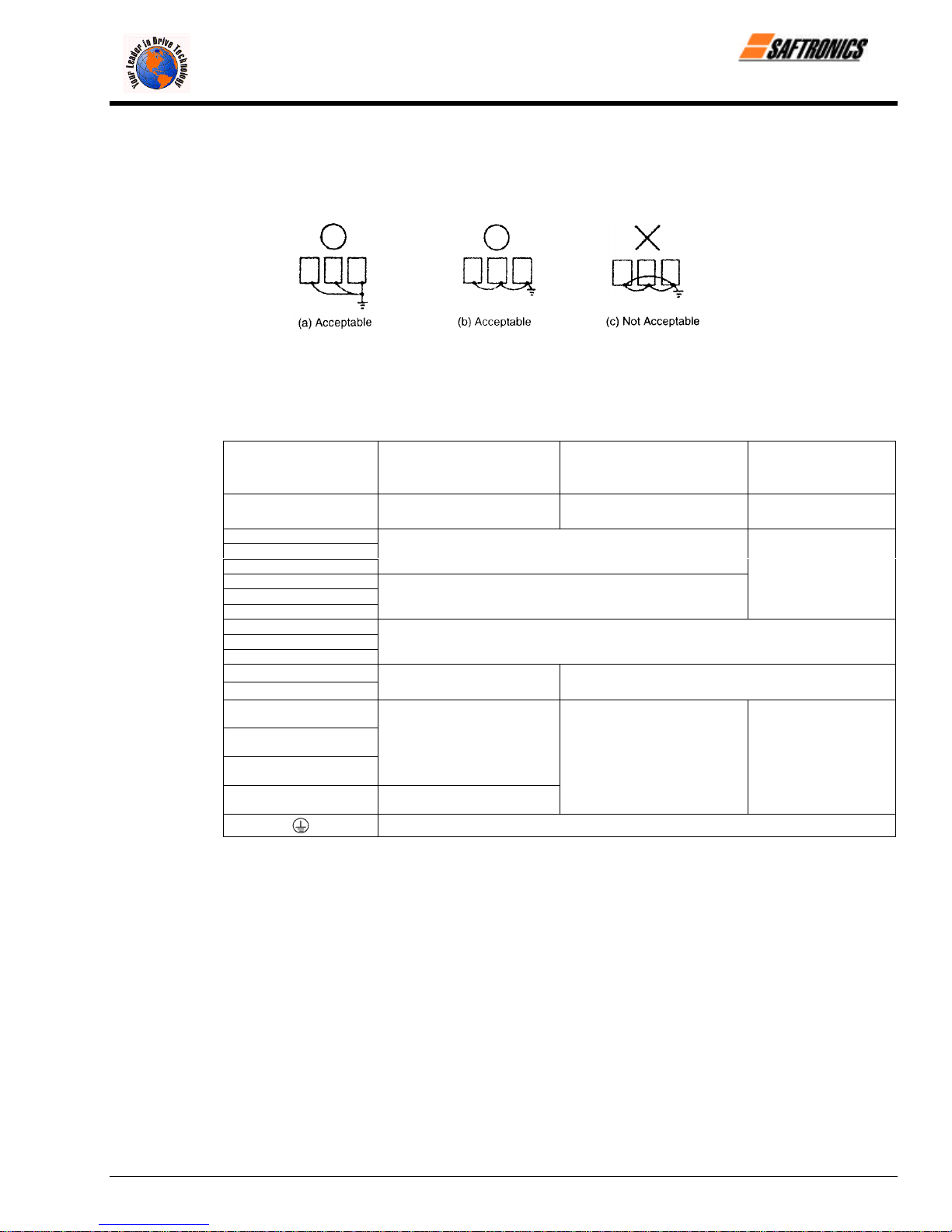
• When using several Inverter units side by side, ground the units as shown in Figure 10, (a) or (b). Do not loop the
ground wires as shown in (c).
Figure 10 Grounding of Three Inverter Units
3.2.4 Functions of Main Circuit Terminals
The following table outlines the functions of the main circuit terminals. Wire according to each terminal function.
Table 3 200 V Class Terminal Functions
Chapter 3: Wiring
Models
FP5/GP5
Max Applicable Motor
Output
L1 (R)
L2 (S)
L3 (T)
L11 (R1)
L21 (S1)
L31 (T1)
T1 (U)
T2 (V)
T3 (W)
B1
B2
Ö
¾ 1
¾ 2
¾ 3
23P7 to 27P5 2011 to 2015 2018 to 2075
3.7 to 7.5 kW 11 to 15 kW 18.5 to 75 kW
Main circuit input power supply
Inverter output
Braking Resistor Unit
• DC Reactor (¾1 − ¾2)
• DC bus terminals (¾1 − ¾2
Ground terminal (Ground resistance: 100 Ω or less)
• DC Reactor (¾1 − ¾2)
• DC bus terminals (¾1 − ¾2
• Braking Unit (¾3 − Ö)
Main circuit input
power supply
Firmware – S2011 and S3012
Revision: 1 (9/98) 13 © Saftronics, Inc.

Chapter 3: Wiring
efesotomasyon.com - Control Techniques,emerson,saftronics -ac drive-servo motor
Table 4 400 V Class Terminal Functions
Models
FP5/GP5
Max Applicable Motor
Output
L1 (R)
L2 (S)
L3 (T)
L11 (R1)
L21 (S1)
L31 (T1)
T1 (U)
T2 (V)
T3 (W)
B1
B2
Ö
¾ 1
¾ 2
¾ 3
r (l 1)
s 200 (l 2 200)
s 400 (l 2 400)
40P4 to 4015 4018 to 4045 4055 to 4160 4185 to 4300
0.4 to 15 kW 18.5 to 45 kW 55 to 160 kW 185 to 300 kW
Main circuit input
power supply
Braking Resistor Unit
• DC Reactor
(¾1 − ¾2
• DC bus terminals
(¾1 − Ö)
Main circuit input power supply
Inverter output
Ground terminal (Ground resistance: 10Ω or less)
• Braking Unit (¾ 3 − Ö)
• Braking Unit (¾ 3 − Ö)
Cooling fan power supply
(Control power supply
r (l 1) − s 200 (l 2 200):
200 to 230 VAC input
r (l 1) − s 400 (l 2 400):
380 to 460 VAC input
Main circuit input
power supply
Firmware – S2011 and S3012
Revision: 1 (9/98) 14 © Saftronics, Inc.

3.2.5 Main Circuit Configuration
efesotomasyon.com - Control Techniques,emerson,saftronics -ac drive-servo motor
200V Class
FP5/GP523P7 to FP5/GP527P5 FP5/GP52011 to FP5/GP52015
FP5/GP52018 to FP5/GP52022 FP5/GP52030 to FP5/GP52075
Chapter 3: Wiring
= The wiring has been completed at the factory prior to shipping.
‡ When installing a DC Reactor (option) on models of 15kW or below, remove the short-circuit bar between
¾ 1 and ¾2 terminals and connect a DC Reactor with the terminals.
Firmware – S2011 and S3012
Revision: 1 (9/98) 15 © Saftronics, Inc.

Chapter 3: Wiring
efesotomasyon.com - Control Techniques,emerson,saftronics -ac drive-servo motor
400V Class
FP5/GP540P4 to FP5/GP541P5 FP5/GP542P2 to FP5/GP54015
FP5/GP54018 to FP5/GP54045 FP5/GP54055 to FP5/GP54160
FP5/GP54185 to FP5/GP54300
= The wiring has been completed at the factory prior to shipping.
‡ When installing a DC Reactor (option) on models of 15kW or below, remove the short-circuit bar between
¾ 1 and ¾ 2 terminals and connect a DC Reactor with the terminals.
Firmware – S2011 and S3012
Revision: 1 (9/98) 16 © Saftronics, Inc.

3.2.6 Parts Required for Wiring
efesotomasyon.com - Control Techniques,emerson,saftronics -ac drive-servo motor
Select wires or Closed-Loop Connectors to be used for wiring from Tables 5, 6 and 7.
Circuit
Model
FP5/GP5
Table 5 200 V Class Wire Size
Terminal Symbol
Terminal
Screw
Wire Size
=
AWG mm
Chapter 3: Wiring
2
Wire Type
Main
Control
23P7 M4 10 5.5
25P5 M5
(U, V, W)
L1, L2, L3, (R, S, T) Ö, ¾ 1, ¾ 2, B1, B2, T1, T2, T3
(U, V, W)
8 8
10-8 5.5 − 8
L1, L2, L3, (R, S, T) Ö, ¾ 1, ¾ 2, B1, B2, T1, T2, T3
27P5 M5
(U, V, W)
L1, L2, L3, (R, S, T) Ö, ¾ 1, ¾ 2, B1, B2, T1, T2, T3
8 8
10-8
2011 M6
V, W)
L1, L2, L3, (R, S, T) Ö, ¾ 1, ¾ 2, ¾ 3, T1, T2, T3 (U,
4 22
8 8
2015
L1, L2, L3, (R, S, T) Ö, ¾ 1, ¾ 2, ¾ 3, T1, T2, T3 (U,
V, W)
M8 3 30
M6 8 8
L1,L2, L3, (R, S, T) L11, L21, L31, (R1, S1, T1), T1,
2018 M8
T2, (U, V, W)
3 30
6 14
L1,L2, L3, (R, S, T), L11, L21, L31, (R1, S1, T1), T1,
2022 M8
T2, T3 (U, V, W)
2 38
6 14
2030
L1,L2, L3, (R, S, T), L11, L21, L31, T1, T2, T3, (U, V,
W)
M10 4/0 100
M8 4 22
2037
L1,L2, L3, (R, S, T), L11, L21, L31, T1, T2, T3, (U, V,
W)
M10 1/0 x 2P 60 5 2P
M8 4 22
2045
L1,L2, L3, (R, S, T), L11, L21, L31, T1, T2, T3, (U, V,
W)
M10 1/0 x 2P 60 5 2P
M8 4 22
2055
L1,L2, L3, (R, S, T), L11, L21, L31, T1, T2, T3, (U, V,
W)
M10 1/0 x 2P 60 5 2P
M8 3 30
2075
L1,L2, L3, (R, S, T), L11, L21, L31, T1, T2, T3, (U, V,
W)
M12 4/0 x 2P 100 5 2P
M8 1 50
S1, S2, S3, S4, S5, S6, SC,
Common to
all models
FV, FI, FS, FC,
AM, AC, M1, M2, MA, MB, MC
20-16
G M3.5 20-14
5.5 − 8
Stranded
0.5 − 1.25
Solid
0.5 − 1.25
0.5 − 2
Power cable:
600V vinyl
sheathed wire
or equivalent
Twisted
shielded wire
= Where size is determined using 75°C temperature-rated copper wire.
Firmware – S2011 and S3012
Revision: 1 (9/98) 17 © Saftronics, Inc.

Chapter 3: Wiring
efesotomasyon.com - Control Techniques,emerson,saftronics -ac drive-servo motor
Circuit
Model
FP5/GP5
Table 6 400 V Class Wire Size
Terminal Symbol
Terminal
Screw
Wire Size
=
AWG mm
2
Wire Type
Main
40P4 M4 2 − 5.5
(U, V, W)
L1, L2, L3 (R, S, T), Ö, ¾ 1, ¾ 2, B1, B2, T1, T2, T3
L1, L2, L3, (R, S, T), Ö, ¾ 1, ¾ 2, B1, B2, T1, T2, T3
40P7 M4
(U, V, W)
2 − 5.5
L1, L2, L3, (R, S, T), Ö, ¾ 1, ¾ 2, B1, B2, T1, T2, T3
41P5 M4
(U, V, W)
2 − 5.5
L1, L2, L3 (R, S, T), Ö, ¾ 1, ¾ 2, B1, B2, T1, T2, T3
42P2 M4
(U, V, W)
L1, L2, L3 (R, S, T), Ö, ¾ 1, ¾ 2, B1, B2, T1, T2, T3
43P7 M4
(U, V, W)
14-10
12-10
2 − 5.5
2 − 5.5
3.5 − 5.5
L1, L2, L3 (R, S, T), Ö, ¾ 1, ¾ 2, B1, B2, T1, T2, T3
44P0 M4
(U, V, W)
2 − 5.5
L1, L2, L3 (R, S, T), Ö, ¾ 1, ¾ 2, B1, B2, T1, T2, T3
45P5 M4 12-10 3.5 − 5.5
(U, V, W)
Power cable:
600V vinyl
sheathed wire
or equivalent
47P5 M5 8-6 5.5
4011
(U, V, W)
L1, L2, L3, (R, S, T), Ö, ¾ 1, ¾ 2, B1, B2, T1, T2, T3
(U, V, W)
M5 8-6
M6 8 8
L1, L2, L3 (R, S, T), Ö, ¾ 1, ¾ 2, B1, B2, T1, T2, T3
4015
L1, L2, L3 (R, S, T), Ö, ¾ 1, ¾ 2, B1, B2, T1, T2, T3
(U, V, W)
M5 8-6
M6 8 8
4018
L1, L2, L3 (R, S, T), L11, L21, L31 (R1, S1, T11), T1,
T2, T3 (U, V, W)
M6 6 14
M8 8 8
4022
L1, L2, L3 (R, S, T), L11, L21, L31 (R1, S1, T11), T1,
T2, T3 (U, V, W)
M6 4 22
M8 8 8
L1, L2, L3 (R, S, T), L11, L21, L31 (R1, S1, T11), T1,
4030 M8
T2, T3 (U, V, W)
= Where size is determined using 75°C temperature-rated copper wire.
8 − 14
8 − 14
4 22
8 8
Firmware – S2011 and S3012
Revision: 1 (9/98) 18 © Saftronics, Inc.

Table 6 400 V Class Wire Size (Continued)
efesotomasyon.com - Control Techniques,emerson,saftronics -ac drive-servo motor
Circuit
Model
FP5/GP5
Terminal Symbol
L1, L2, L3 (R, S, T), L11, L21, L31 (R1, S1, T11), T1,
4037 M8
T2, T3 (U, V, W)
L1, L2, L3 (R, S, T), L11, L21, L31 (R1, S1, T11), T1,
4045 M8
T2, T3 (U, V, W)
L1, L2, L3 (R, S, T), L11, L21, L31 (R1, S1, T11), T1,
4055
T2, T3 (U, V, W)
L1, L2, L3 (R, S, T), L11, L21, L31 (R1, S1, T11), T1,
4075
T2, T3 (U, V, W)
L1, L2, L3 (R, S, T), L11, L21, L31 (R1, S1, T11), T1,
4110
Main
4160
T2, T3 (U, V, W)
L1, L2, L3 (R, S, T), L11, L21, L31 (R1, S1, T11), T1,
T2, T3 (U, V, W)
L1, L2, L3 (R, S, T), Ö, ¾ 1, ¾ 3, T1, T2, T3 (U, V, W)
4185
r (l1), s 200 (l2 200), s 400 (l
L1, L2, L3 (R, S, T), Ö, ¾ 1, ¾ 3, T1, T2, T3 (U, V, W)
400)
2
4220
r (l1), s 200 (l2 200), s 400 (l
L1, L2, L3 (R, S, T), Ö, ¾ 1, ¾ 3, T1, T2, T3 (U, V, W)
400)
2
4300
Control
Common to
all models
r (l1), s 200 (l2 200), s 400 (l
S1, S2, S3, S4, S5, S6, SC,
FV, FI, FS, FC,
AM, AC, M1, M2, MA, MB, MC
G M3.5 20-14
400)
2
= Where size is determined using 75°C temperature-rated copper wire.
Terminal
Screw
Wire Size
AWG mm
3 30
6 14
1 50
6 14
M10 4/0 100
M8 4 22
M10 1/0 x 2P 60 x 2P
M8 4 22
M10 1/0 x 2P 60 x 2P
M8 3 30
M12 4/0 x 2P 100 x 2P
M8 1 50
M16
M8 1 50
M4 20-10
M16
M8 1/0 60
M4 20-10
M16
M8 1/0 60
M4 20-10
650MCM
x 2P
650MCM
x 2P
650MCM
x 2P
20-16
325 x 2P
0.5 − 5.5
325 x 2P
0.5 − 5.5
325 x 2P
0.5 − 5.5
Stranded
0.5 − 1.25
0.5 − 1.25
0.5 − 2
Chapter 3: Wiring
=
2
Solid
Wire Type
Power cable:
600V vinyl
sheathed wire
or equivalent
Twisted
shielded wire
Firmware – S2011 and S3012
Revision: 1 (9/98) 19 © Saftronics, Inc.
Chapter 3: Wiring
efesotomasyon.com - Control Techniques,emerson,saftronics -ac drive-servo motor
Table 7 Closed-Loop Connectors
AWG Size Wire Size mm
2
20 0.5
18 0.75
16 1.25
14 2
12-10 3.5 / 5.5
8 8
6 14
4 22
3-2 30 / 38 M8
1-1/0 50 / 60
3/0 80
4/0 100
4/0 100
300MCM 150
400MCM 200
650MCM 325
Terminal Screw Closed-Loop Connectors
M3.5
M4
M3.5
M4
M3.5
M4
M3.5
M4
M5
M6
M8
M4
M5
M6
M8
M5
M6
M8
M6
M8
1.25 − 3.5
1.25 − 4
1.25 − 3.5
1.25 − 4
1.25 − 3.5
1.25 − 4
2 − 3.5
2 − 4
2 − 5
2 − 6
2 − 8
5.5 − 4
5.5 − 5
5.5 − 6
5.5 − 8
8 − 5
8 − 6
8 − 8
14 − 6
14 − 8
M6 14 - 6
M8 14 - 8
38 − 8
M8
M10
M10
60 − 8
60 − 10
80 − 10
100 − 10
100 − 12
M12
150 − 12
200 − 12
M12 x 2
M16
325 − 12
325 − 16
NOTE: When determining wire size, consider voltage drop. Select a wire size so that voltage drop will be less than 2% of the normal
rated voltage. Voltage drop is calculated by the following equation:
Phase-to-phase voltage drop (V) = /3 5 wire resistance (Ω/km) 5 wiring distance (m) 5 current (A) 5 10
−3
Firmware – S2011 and S3012
Revision: 1 (9/98) 20 © Saftronics, Inc.

3.3 Wiring the Control Circuit
efesotomasyon.com - Control Techniques,emerson,saftronics -ac drive-servo motor
The following table outlines the functions of the control circuit terminals. Wire according to each terminal function.
3.3.1 Functions of Control Circuit Terminals
Classification
Terminal Signal Function Description Signal Level
S1 Forward run/stop Forward run when closed, stop when open
Chapter 3: Wiring
Table 8 Control Circuit Terminals
S2 Reverse run/stop
S3 External fault input
S4 Fault reset input Reset when closed
S5 Multi-step speed reference 1 Effective when closed
Sequence Input Signal
Analog Input Signal
S6 Multi-step speed reference 2 Effective when closed
SC
FS
FV
FI
FC
G
M1
M2
Sequence control input
common terminal
+ 15 V
Power supply output
Frequency reference input
(voltage)
Frequency reference input
(current)
Common terminal for control
circuit
Connection to shield sheath
of signal lead
During running (NO contact) Closed when running
Reverse run when closed,
stop when open
Fault when closed,
normal state when open
Multi-function contact
inputs (n035 to n039)
For analog command + 15 V power supply
0 to + 10 V/100% 0 to + 10 V (20 kΩ)
4 to 20 mA/100%
0 V
n042 = 0 : FV
effective
n042 = 1 : FI
effective
Multi-function
contact output
(n041)
Photo-coupler insulation
Input: + 24 VDC 8 mA
+ 15 V
(Allowable current 20 mA
maximum)
4 to 20mA (250Ω)
Dry contact
Contact capacity:
250 VAC 1 A or less
30 VDC 1 A or less
MA
MB
Sequence Output Signal
Analog Output
G
Firmware – S2011 and S3012
Revision: 1 (9/98) 21 © Saftronics, Inc.
MC
AM Frequency meter output
Signal
AC Common
S1 S2 S3 SC SC S4 S5 S6 FV FI FS FC AM AC M1 M2 MA MB MC
Fault contact output (NO/NC
contact)
Figure 11 Control Circuit Terminal Arrangement
Fault when closed between
Terminals MA and MC.
Fault when open between
Terminals MB and MC.
0 to + 10 V/100% frequency
Multi-function
contact output
(n040)
Multi-function
analog monitor 1
(n048)
Dry contact
Contact capacity:
250 VAC 1 A or less
30 VDC 1 A or less
0 to + 10 V 2 mA or less

Chapter 3: Wiring
efesotomasyon.com - Control Techniques,emerson,saftronics -ac drive-servo motor
3.3.2 Wiring the Control Circuit Terminals
Insert the wire into the lower part of the terminal block and connect it tightly with a screwdriver. Wire sheath strip length
must be 7 mm (approximately ¼ inch).
3.3.3 Precautions on Control Circuit Wiring
• Separate control circuit wires from main circuit wires and other power cables to prevent erroneous operation caused
by noise interference.
• Use twisted shielded or twisted-pair shielded wire for the control circuit line and connect the shielded sheath to the
Inverter Terminal G. See Figure 12.
3.4 Wiring Inspection
After completing installation and wiring, check for the following items. Never use control circuit megger check.
o Wiring is proper.
o Wire clippings or screws are not left in the unit.
o Screws are securely tightened.
o Bare wire in the terminal does not contact other terminals.
Figure 12 Shielded Wire Termination
Firmware – S2011 and S3012
Revision: 1 (9/98) 22 © Saftronics, Inc.
 Loading...