

Saft SUN+ 405, SUN+ 250, SUN+ 305, SUN+ 355, SUN+ 455 Installation And Operating Instructions Manual
...
Sunica.plus Ni-Cd batteries
Installation and operating instructions
December 2013
Important recommendations
■ Never allow an exposed flame or spark
near the batteries particularly while
charging.
■ Never smoke while performing any
operation on the battery.
■ For protection, wear rubber gloves, long
sleeves, and appropriate splash goggles
or face shield.
■ The electrolyte is harmful to skin and
eyes. In the event of contact with skin
or eyes, wash immediately with plenty
of water. If eyes are affected, flush
with water, and obtain immediate
medical attention.
■ Remove all rings, watches and other
items with metal parts before working
on the battery.
■ Use insulated tools.
■
Avoid static electricity and take measures
for protection against electric shocks.
■ Discharge any possible static electricity
from clothing and/or tools by touching
an earth-connected part "ground" before
working on the battery.
1. Receiving the shipment
Do not overturn the package. Check the
packages and cells for transport damage.
The cells are shipped filled and charged, and
is ready for immediate use.
Transport seals are located under the lid of
each vent, they must be removed prior to
mounting.
The cells must never be charged with the
plastic transport seals in place as this is
dangerous and can cause permanent
damage.
2. Storage
Store the cells indoors in a dry, clean, cool
location (0°C to +30°C / +32°F to +86°F)
and well ventilated space on open shelves.
Storage of filled cells at temperatures above
+30°C (+86°F) can result in loss of capacity.
This can be as much as 5% per 10°C
(18°F) above +30°C (+86°F) per year.
Do not store in direct sunlight or expose to
excessive heat.
Sunica.plus batteries are supplied filled with
electrolyte and charged, they can be stored
in this condition for maximum 2 years
from date of shipment.
Never drain the electrolyte from the cells.
3. Installation
3.1. Location
Install the battery in a dry and clean room.
Avoid direct sunlight and heat. The battery
will give the best performance and maximum
service life when the ambient temperature is
between +10°C to +30°C / +50°F to +86°F
3.2. Ventilation
During the last part of charging, the battery
is emitting gases (oxygen and hydrogen
mixture). At normal float charge, the gas
evolution is very small but some ventilation
is necessary.
Note that special regulations for
ventilation may be valid in your area
depending on the application.
3.3. Mounting
Verify that cells are correctly interconnected
with the appropriate polarity. The battery
connection to load should be with nickel
plated cable lugs.
Recommended torques for terminal
bolts are:
• M6 = 11 ± 1.1 N.m (97.4 ± 9.8 lbf.in)
• M8 = 20 ± 2 N.m (177.0 ± 17.7 lbf.in)
• M10 = 30 ± 3 N.m (265.0 ± 26.6 lbf.in)
The connectors and terminals should be
corrosion-protected by coating with a thin
layer of anti-corrosion oil.
Remove the transport seals and close the
vent caps.
If a central water filling system is used as an
option, refer to the corresponding
installation and operating instructions sheet.
3.4 Electrolyte
When checking the electrolyte levels,
a fluctuation in level between cells is not
abnormal and is due to the different
amounts of gas held in the separators
of each cell. The level should be at least
15 mm above the minimum level mark
and there is normally no need to adjust it.
Do not top-up prior to initial charge.
After commissioning, when the level is
stabilized, it should be not less than
5 mm below the maximum level mark.
4. Commissioning
Verify that the transport seals are removed
and the ventilation is adequate during the
operation.
A good commissioning is important.
Charge at constant current is preferable.
If the current limit is lower than indicated
in the table A, charge for a proportionally
longer time.
.
4.1. Cells stored up to 6 months:
A commissioning charge is normally not
required and the cells are ready for immediate
use. If full performances are necessary
immediately, a commissioning charge as
mentioned in section 5.4. is recommended.
4.2. Cells stored more than 6 months
and up to 2 years:
A commissioning charge is necessary.
• Commissioning at ambient temperature
between +10°C to +30°C
(+50°F to +86°F)
- Constant current charge:
20 h at 0.1 C
(see table A)
Note: At the end of the charge, the cell
voltage will reach the level of 1.75V/cell,
thus the charger shall be able to supply
such voltage.
When the charger maximum voltage
setting is too low to supply constant
current charging, divide the battery in two
parts to be charged individually.
- Constant potential charge: 1.55 V/cell
for a minimum of 24 hours with current
limited to 0.1 C
Table A).
• Commissioning at ambient temperature
above +30°C (+50°F)
- Only constant current charge:
20 h at 0.1 C
The electrolyte temperature is to be
monitored during charge. If the
temperature exceeds +45°C (+113°F)
during charging, then it must be stopped to
reduce the temperature. The charging can
be resumed when electrolyte temperature
drops below +40°C (+104°F).
In the case of remote areas, where
the only charger available is the photovoltaic
array, the battery should be connected to the
system with no connected load and no
voltage limit. The battery should then be
charged in good sunshine conditions. During
this operation, the Ah charged shall be in the
magnitude of 1.6 time the rated capacity,
and, in order to limit the risk of electrolyte
overflow, it is recommended not to exceed
the charge current value specified
in the Table A.
A recommended
5
A (see the current in
5
recommended.
5
Sunica.plus Ni-Cd batteries
4.3. Cell electrolyte after prolonged float
charge:
Check the electrolyte level and adjust it to the
upper level mark by adding distilled or
deionized water.
Note: When full battery performance is
required for capacity test purposes, the
battery has to be charged in accordance
with IEC 62259 section 7 (7.1 & 7.2).
5. Charging in service
The photovoltaic array converts solar
irradiance into DC electrical power at a predetermined range of voltages whenever
sufficient solar radiation is available. Unlike a
main connected system, the output from a
photovoltaic array is variable and, to obtain
the best efficiency from the system, it is quite
normal to have some form of charge control.
Two main techniques for charging the
batteries are generally used in photovoltaic
systems.
These are those which have a constant
voltage limitation based on the PWM technics
and those with several voltage steps charging
where the battery, by switching means, is
charging up to a high pre-set voltage (boost
or float threshold), then drops to a lower
voltage level (battery reconnect threshold)
and then back to the high pre-set voltage
and so on.
Recommended charging voltages for a typical
photovoltaic application sized for
5 days or more back up time:
a) case of constant voltage limitation (PWM
regulator system or similar)
• float: 1.50 V/cell
• boost (not mandatory): 1.65 V/cell
b) case of regulators based on the switching
principle:
• boost threshold (not mandatory):
1.65 V/cell
• float threshold: 1.55 V/cell
• battery reconnect threshold:
1.45 V/cell
For lower back-up time, the values have to be
increased depending of the load requirement.
Consult the manufacturer.
For use in warm areas, a temperature
compensation on the charge voltage is not
recommended.
For use in cold areas, a temperature
compensation is recommended to increase
the charge acceptance.
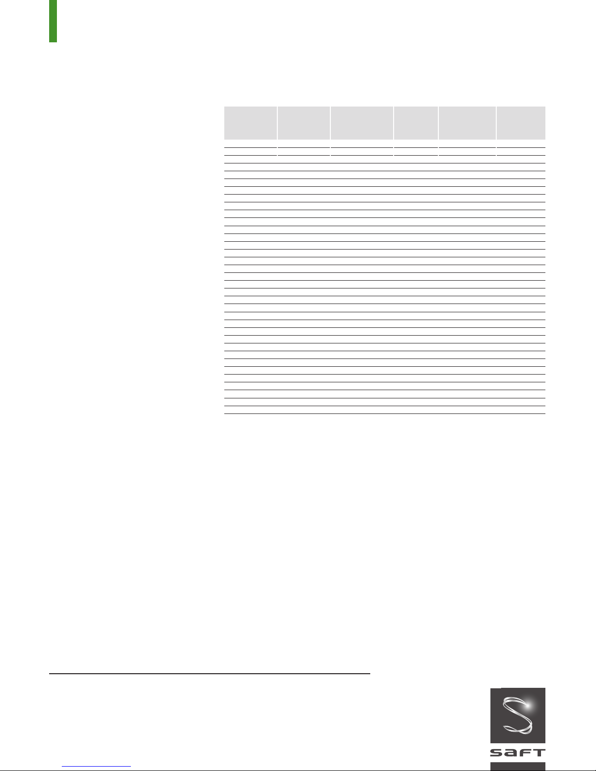
Table A:
Rated Nominal Capacity Charging Max. quantity Cell
Cell type
SUN+ 100 95 100 9,5 280 M8
SUN+ 150 140 150 14,0 380 M10
SUN+ 200 185 200 19,0 500 M10
SUN+ 250 235 250 24,0 590 M10
SUN+ 305 280 305 28,0 700 M10
SUN+ 355 325 355 33,0 880 2xM10
SUN+ 405 375 405 38,0 1000 2xM10
SUN+ 455 420 455 42,0 1100 2xM10
SUN+ 505 470 505 47,0 1200 2xM10
SUN+ 555 515 555 52,0 1300 2xM10
SUN+ 610 560 610 56,0 1400 2xM10
SUN+ 660 610 660 61,0 1600 3xM10
SUN+ 710 650 710 65,0 1700 3xM10
SUN+ 760 700 760 70,0 1800 3xM10
SUN+ 810 750 810 75,0 1900 3xM10
SUN+ 860 800 860 80,0 2000 3xM10
SUN+ 910 840 910 84,0 2100 3xM10
SUN+ 960 890 960 89,0 2300 4xM10
SUN+ 1015 940 1015 94,0 2400 4xM10
SUN+ 1065 980 1065 98,0 2500 4xM10
SUN+ 1115 1030 1115 103 2600 4xM10
SUN+ 1170 1080 1170 108 2700 4xM10
SUN+ 1215 1120 1215 112 2800 4xM10
SUN+ 1270 1170 1270 117 3000 5xM10
SUN+ 1320 1220 1320 122 3100 5xM10
SUN+ 1370 1260 1370 126 3200 5xM10
SUN+ 1420 1300 1420 130 3300 5xM10
SUN+ 1470 1350 1470 135 3400 5xM10
SUN+ 1520 1400 1520 140 3500 5xM10
SUN+ 1570 1450 1570 145 3700 5xM10
SUN+ 1620 1500 1620 150 3800 6xM10
SUN+ 1670 1550 1670 155 3900 6xM10
SUN+ 1720 1600 1720 160 4000 6xM10
SUN+ 1775 1650 1775 165 4100 6xM10
SUN+ 1830 1700 1830 170 4200 6xM10
The recommended value is:
–3.0 mV/°C/cell (–1.68 mV/°F/cell)
starting from +20°C (+68°F).
6. Periodic Maintenance
■ In a correctly designed standby
application, Sunica.plus requires the
minimum of attention.
However, it is good practice with any system
to carry out an inspection of the system once
per year or at the recommended topping-up
interval period to ensure that the charging
system, the battery and the ancillary
electronics are all functioning correctly.
■ When this system service is carried out,
it is recommended that the following
actions should be taken:
• Keep the battery clean using only water.
Do not use a wire brush or solvents of
any kind. Vent plugs can be rinsed in
clean water if necessary.
• Check visually the electrolyte level.
Never let the level fall below the minimum
Capacity 5 h - 120 h - 1.00 V Current of water connection
C
h 1,00 V Ah C
5
(Ah) (Ah) (A) in cc per pole
Ah 0.1 C5A to be added bolt
120
level mark. Use only distilled or deionized
water to top-up (see Table A for the
quantity of water per cell). Topping up of
the Sunica.Plus battery shall be carried
out when battery is fully charged.
Experience will tell the time interval
between topping-up.
Note: There is no need to check the
electrolyte density periodically.
Interpretation of density measurements is
difficult and could be misleading.
• Check every two years that all
connectors are tight.
• The connectors and terminal bolts should
be corrosion-protected by coating with a
thin layer of anti-corrosion oil.
•
High water consumption is usually caused
by improper voltage setting of the charger.
7. Environment
To protect the environment all used batteries
must be recycled. Contact your local Saft
representative for further information.
Saft
Industrial Battery Group
12, rue Sadi Carnot
93170 Bagnolet - France
Tel: +33 1 49 93 19 18
Fax: +33 1 49 93 19 64
www.saftbatteries.com
Doc N° 21885-2-1213
Data in this document is subject to change without
notice and becomes contractual only after written
confirmation.
Société par Actions Simplifiée
au capital de 31 944 000
RCS Bobigny B 383 703 873
Le Révérend Imprimeur - Printed in France - 1k
€
 Loading...