

Evolion® 3.9 kWh
Installation and operation instruction sheet
1. Introduction
The Evolion® is a Li-ion battery system that includes large format Li-ion cells and
necessary electronics for automatic interruptions or regulated operations when un-safe
limit is exceeded and detected.
This sheet is a quick start guide. It describes how to install and operate the Evolion®
in a legacy battery mode, i.e., with no RS485/Modbus communication connected.
Within this sheet, the necessary tasks are noted with
they should be conducted. Use the Evolion® 3.9 kWh historical data sheet (included)
for records. Make sure to read the Evolion® 3.9 kWh Installation and Operation User
Manual (UM), the Evolion® 3.9 kWh Technical Manual (TM) and the Evolion® Toolbox
Software User Manual (CM). Check with your local Saft Representative for more details.
2. Safety
Misusing the Evolion® may cause an event
like cell venting, overheating or igniting.
Read these instructions fully before
installing and operating the Evolion®.
Do not short-circuit the power
terminals.
Do not reverse connect the power
cables to the charger.
Do not disassemble the unit.
Do not drop the unit.
Do not immerse the unit.
Do not expose the unit to fire or
temperature higher than 80°C
(176°F).
Connect only to telecom power
systems/rectifiers with a maximum
rated output of 60 V.
Refer to the Battery Information
Sheet or BIS (included) for
emergency response procedures
and personal protective equipment
• 15°C to 35°C (59°F to 95°F).
• No direct sunlight, rain or flooding
• Up to 1 year without refreshing charge
in case of an abnormal event.
If smoke is emitted from the
module, stay clear of the smoke and
evacuate the area immediately.
For normal handling and operation
according to this installation and
operation sheet, no personal
protective equipment is required.
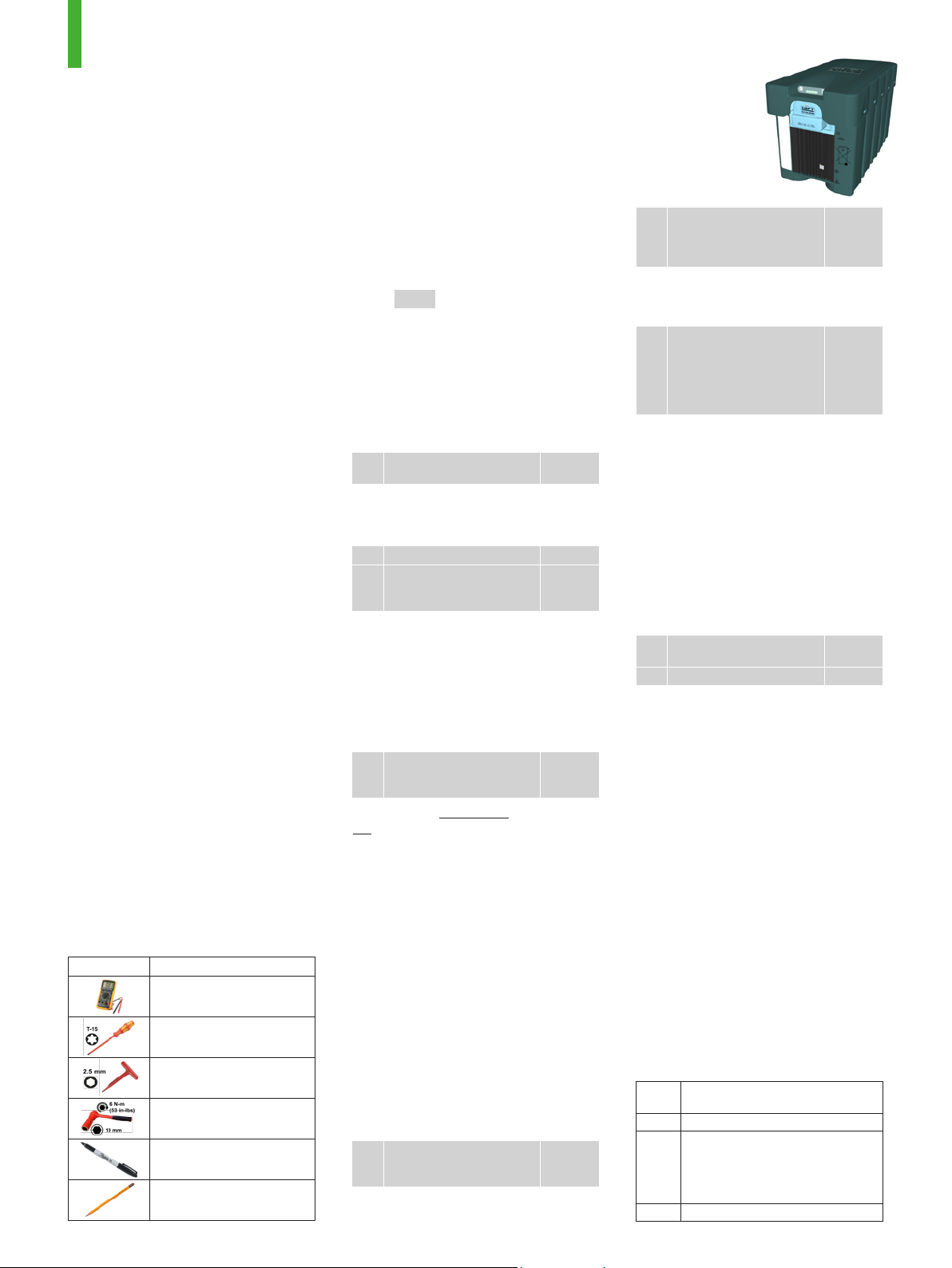
3. Tools
These tools are needed and are not
provided.
Tool Use
Voltage and fuse continuity
Front cover removal/
replacement
Grounding point screw
Power and fuse terminals
External case notations
BMST reset button
• Use the original packaging or equivalent.
• Secure the Evolion® in place
• The Evolion® must be OFF.
7. Installation
Ev#’s
and they are in order that
4. Unpacking and Inspection
The Evolion® is packaged in accordance
with UN3480 Class 9 Group 2. See
Figure 1 for lifting instructions.
Check that all items are
Ev1
received.
Table 1
If items were not received or if anything
was damaged do not install the module
and contact your local Saft representative.
Study Evolion
Ev2
Check the state after
Ev3
receiving and before
storage or installation.
®
features. Figure 3
Figure 1
Figure 4
Table 2
Always keep the Evolion® module and its
kit in its original packaging, together.
5. Storage
Store the battery in its original packaging.
After 6 months, check the
Ev4
state once per month in
storage.
Table 2
Figure 4
IMPORTANT: Never leave the Evolion®
ON when it is not in use. The internal
electronics will self-discharge the cells
to a low voltage alarm level which may
render the module un-usable.
6. Transportation
Follow the necessary transportation
rules for Li-ion batteries by consulting
with your company’s standard practice
and your local transportation regulations.
Before installing, make sure the right
number of Evolion® you will connect to
one bus is properly sized. Consult with
your local Saft Representative or consult
with the Evolion® TM.
Size the proper number
Ev5
of Evolion® to connect to
one bus.
Before installing, double check the state
of each Evolion®.
Evolion
TM
May 2016
Check for a maximum of
2 V difference allowed
Ev6
between modules that will
operate on the same bus.
If modules have more than 2 V difference
equalizing the Evolion® modules is
necessary, refer to the Evolion® UM.
For modules that will
operate on the same bus,
set each with a unique
Ev7
Node ID, manually between
1 to 4 or using the Evolion
Toolbox Software.
The Evolion® can be installed and
operated in Network Telecommunication
Facilities including un-manned OSP. The
Evolion® can be placed on shelves or in
battery compartments with the following
characteristics.
• IP54 (NEMA3) or higher
• -40°C to 75°C (-40°F to 167°F)
• 95% RH max. (non-condensing)
• Up to 3000 meters (9843 feet)
• No blocking the heat sink and vent ports
• Right side up or sideways
Connect the Evolion
Ev8
modules.
Ev9 Power ON
®
8. Operation/Maintenance
The Evolion® provides un-interrupted standby
power anytime the AC power supply is
OFF. Continue trouble free operation in
accordance with these instructions.
The Evolion® requires no maintenance,
but periodically checking it during other
site routines is recommended.
• LED state (Table 3 and 9.
Troubleshooting)
• SOC and SOH (Table 2)
• Heat sink area un-obstructed
• Clean any excessive dirt build-up using a
nonmetallic brush or a dry or damp cloth.
• Do not use any cleaning solvents or soaps.
• Do not immerse, bathe or hose off the
Evolion®.
9. Troubleshooting
When the Evolion® is in service, observe
the LED's. See Table 3 for operation
LED state.
LED
Refer to
state
D Evolion® TM, Appendix E
®
E Evolion® TM, Appendix E; Figure 11
IMPORTANT: The Evolion® must
be re-charged within 2 weeks after
Alarm #36 was activated or the
module may be rendered useless.
G Figure 11
Figure 1
Figure 4
Figure 6
(manual)
or
®
Evolion
®
CM
(software)
Figure 8
Figure 9
Figure 10
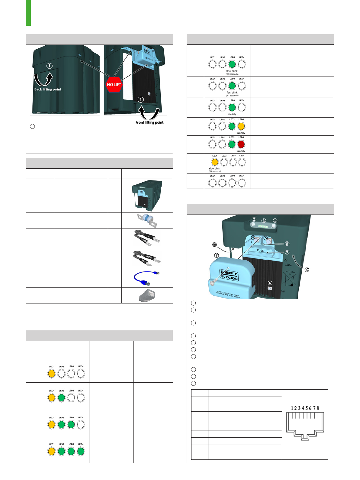
Figure 1. Lifting
Table 3. Operating LED legend (no push button)
# LED state Description
1
Only use the lifting points.
NOTE: The Evolion® weighs 30 kg (66 lbs).
IMPORTANT: Using other than the lifting points shown may
cause irreparable damage.
Table 1. Included with the Evolion® kit, 782674 (-11)
P/N Description Qty Illustration
782672-
XX
(Note 1)
781081
772516
(Note 2)
Evolion® 3.9 kWh
module
Fuse, replaceable,
spare
Power cable, 8
GA., ¼” ring lugs,
positive, 1 meter
1
1
1
A
B
Floating or Forbidden Charge
Mode (warning alarm #11)
Charging in fast charge mode
or regulated charge mode
C Discharging
Warning alarm
D
(Note 1)
E
(Note 1)
(continues normal operation),
See 9. Troubleshooting
Major alarm (disconnected),
See 9. Troubleshooting
Bootloader mode
F
(only when used with
®
Evolion
Toolbox Software)
G Sleep or OFF
Note 1: To diagnose the alarms, use the Evolion® Toolbox Software
available in the Evolion® Communication Kit (772309)
Figure 3. Evolion® features
772517
(Note 2)
772518
773455
Note 1: The kit variant is indicated by the”-XX”. The standard kit is
Note 2: The power cable assembly and part number may vary based on
Power cable, 8
GA., ¼” ring lugs,
negative, 1 meter
Comm. cable, RJ45
male (x2), 1 meter
Resistor cap, RJ45
male
shown in Table 1 is the -11 variant.
the kit variant.
1
1
1
Table 2. SOC/SOH LED legend (after pushing button)
# LED state
1
2
3
4
SOC
(Push < 3 sec.)
(LED’s steady)
< 25% SOC
charge is
necessary
≥ 25% SOC
Store
(7 months)
or operate
≥ 50% SOC
Store
(13 months)
or operate
≥ 75% SOC
Store
(20 months)
or operate
SOH
(Push ≥ 3 sec.)
(LED’s flashing)
< 25% SOH
< 77% Ah
avail.
≥ 25% SOH
≥ 77% Ah
avail.
≥ 50% SOH
≥ 85% Ah
avail.
≥ 75% SOH
≥ 92% Ah
avail.
1
ON/OFF push button, 2 seconds ON – 4 seconds OFF
2
SOC (State of Charge) and SOH (State of Health) push
button, see Table 2
3
LED1 (left), LED2, LED3 and LED4 (right), see Table 2
and 3
4
Positive power terminal, M6 hex head bolt
5
Negative power terminal, M6 hex head bolt
6
Grounding point, M3 socket head screw
7
Front cover, 3.5 mm x 12 mm, self threading, torx head
screw
8
BMST micro-processor reset button
9
Replaceable fuse (not shown) and cover, use only 771285
10
RJ45 (female) – 2 jacks with pins connected in parallel
Pin Type
1 RS485+
2 RS485-
Ground (isolated from power
3
terminals)
4 Wake up (+12 V to ground)
5 Not used
6 Not used
7 Dry contact alarm loop
8 Dry contact alarm loop

Figure 4. Checking the State
Figure 4 Steps (refer to illustration and tools)
1
Press ON/OFF button for 2 seconds and allow the self-test
to complete. Record the Operating LED state (see Table 3).
CAUTION: When ON, the battery voltage is connected to the
power terminals.
2
Press the SOC/SOH button (See Table 2).
3
Observe and note the LED state for SOC and SOH (See
Table 2).
4
Remove cover and measure and note the terminal
voltage. Replace cover.
5
Press ON/OFF button for 4 seconds to turn OFF the Evolion®.
The Evolion® is now ready for continued storage or service.
Figure 6 Steps (refer to illustration and tools)
CAUTION: Make sure to disconnect the power cables before
conducting these steps.
1
Turn OFF the Evolion
2
Press and hold the SOC/
®
Table F6. Node ID#
LED ID#
SOH button and ON/OFF
button simultaneously for
2 seconds.
3
The current Node ID will be
displayed. See Table F6.
4
To change the Node ID,
press the SOC/SOH button
1
2
3
until the LED indicates a
Node ID between 1 and 4.
4
See Table F6.
5
Press the ON/OFF button
for 4 seconds to turn OFF;
the new Node ID is now set.
6
Scribe the Node ID on the
outside in a visible location.
Note 1: To set a Node ID higher
than 4, use the Evolion®
Toolbox Software.
> 4
(Note 1)
The Evolion® is now ready for continued storage or service.
Figure 8. Connections
Figure 5. Refreshing charge
Figure 5 Steps
1
Connect the power terminals to a telecom rectifier
according to Figure 8.
NOTE: If the voltage is within 0.5 V between the modules,
paralleling and charging more than one module is OK. See
Figure 4 to check module voltage.
2
Before applying power, set the rectifier output voltage
according the Table F5 and the maximum output current
to 21 Amps per Evolion®.
3
Power ON and start charging according to Figure 10.
4
Continue charging for the minimum amount of time
according to Table F5.
5
Turn OFF the rectifier output power and then turn OFF
the Evolion®.
The Evolion® is now ready for continued storage or service.
Table F5. Charging guide
To set %SOC
Max. V
set-point
45% (1 year more storage) 50.5 V ±1.0% 2.5
100% (to put in service) 56.0 V ±1.0% 4.5
Note 1: Based on 21 Amps per Evolion® and 0% SOC at the start of charge.
Chg hours
(Note 1)
Figure 6. Manual Node ID setting (ID # from 1 to 4)
Figure 8 Steps (refer to illustration and tools)
CAUTION: Do not conduct these steps if any Evolion® has more
than 2 V difference. The fuse or power board may be overloaded.
IMPORTANT: Make sure all Evolion® modules are OFF before starting.
1
Make sure the rectifier battery output breakers are open
or disconnected so the power bus is not live with power.
IMPORTANT: Never turn the Evolion® ON using the ON/OFF
button once the power cables are connected to the power
bus to avoid breaking a fuse due to pre-charging a capacitor.
IMPORTANT: Never connect the Evolion® in series.
2
Remove the front cover and connect all the Evolion® power
cables provided (772516, 772517). Replace the front
cover after torqueing the terminals.
NOTE: The recommended terminal torque is 6 N-m
(53 in-lbs) unless otherwise noted on the Evolion®.
NOTE: Either power terminal can connect and operate on
a Common Bonding Network (CBN) or an Isolated Bonding
Network (IBN).
3
Connect all communication cables provided (772518)
between each Evolion®.
4
Connect the RJ45 resistor cap provided (773455).
5
Connect all grounding points on the heat sink face.
NOTE: It is not necessary to ground the heat sink face to function.
The Evolion® modules are now ready to connect communication
according to Figure 9 and Power ON according to Figure 10.
SHUTDOWN procedure:
a
Open the output breaker (1)
b
Turn OFF each Evolion® using the ON/OFF button.
c
Disconnect cables.

Figure 9. Connecting Communication to the Application
A
B
Figure 9 Steps (refer to illustration and tools)
1
Prepare a communication cable to connect to the application.
2
Color match the pins according to 568A or 568B cable.
3
Connect the prepared cable ends to the application.
The Evolion® is now ready for communication and Figure 10.
Table 5. Rectifier settings
IMPORTANT: These setting are necessary in order to avoid
rendering the Evolion® unusable and requiring a site intervention.
# Type Value
a. Single level charge voltage
56.0 V ± 0.5% (all charge
operations) (Note 1)
b. Temp. Comp. V. (TCV) Turned OFF or Disabled
c. Max. re-charge current See Table 6
d. Ramp in voltage
Longest setting up to
3 minutes
e. Default rectifier voltage 42 V to 46 V
f. Low Voltage Disconnect
Note 1: The Evolion® operates normally between 49.5 V to 56.0 V. The
highest %SOC is reduced by 10% for each 1 V below 56.0 V.
45 V (≤ 12 in parallel)
46 V (> 12 in parallel)
Table 6. Maximum Re-charge Current Settings
Duty
4x cycles per day or more 16 A
To avoid
overheating
3x to 4x cycles per day 21 A
2x to 3x cycles per day 24 A
1x to 2x cycles per day 32 A
To avoid charge
regulated mode
Note 1: Make sure to always operate at less than 0.85xIMR or less to
avoid charge regulated mode (see Evolion® TM).
1x cycle per day or less 21 A
Max. per
Evolion® (Note 1)
Figure 10. Powering ON
Figure 10 Steps (refer to illustration and tools)
Make sure the AC power is ON and the rectifier controller is
operating normally.
Make sure the Evolion® modules are turned OFF.
1
Turn ON the rectifier output power. The Evolion® modules
will automatically wake up and begin charging after a few
seconds.
2
Observe the LED’s (see Table 3).
The Evolion® is now in service.
Figure 11. Fuse Check/Replace and BMST reset
Figure 11 Steps (refer to illustration and tools)
CAUTION: Make sure the Evolion® is OFF and disconnected
before conducting these steps.
1
Remove the front cover.
2
Remove the fuse cover.
3
Check the fuse continuity (close to zero ohms = good fuse);
replace fuse (781081) as necessary. Replace fuse cover
4
Turn ON the Evolion
5
Check LED state (Table 3) and push BMST reset button
as necessary to clear alarms.
6
Turn OFF the Evolion®.
The Evolion® is now ready for storage or service.
®
Saft
Industrial Battery Group
12, rue Sadi Carnot
93170 Bagnolet - France
Tel : +33 (0)1 49 93 19 18
Fax: +33 (0)1 49 93 19 64
www.saftbatteries.com
Doc. Nº 21952-0516-2
Edition: May 2016
Data in this document is subject to change without
notice and becomes contractual only after written
confirmation.
Société par Actions Simplifiée au capital de
31 944 000 €
RCS Bobigny B 383 703 873
Produced in the UK by Arthur Associates Limited

Evolion® 3.9 kWh
Historical Data Sheet
Module Label:
P/N S/N Manufacturing Date Software Version Parameters Version
Receiving and Storage:
Ev1: All items received (Table 1)?
Ev3: Use Figure 4 and log the following information:
Month Date
Op. LED state
(Table 3)
Terminal Voltage
(xx.x)
1
2
3
4
5
6
7
8
9
10
11
12
Installation Checklist:
Ev5:
Sizing is correct?
Ev6:
∆V ≤ 2Va?
Ev7:
Node ID# set?
Ev8:
Terminal torque OK?
#
a
This check is required if more than one Evolion® will be installed and operated on one bus.
b
See Table 3
INSTALLATION NOTES:
SOC LED state
(Table 2)
SOH LED state
(Table 2)
Ev9:
Op. LED’s stateb? Installation Date
Date Initials Node ID#
a
See Figure 6 or use the Evolion® Toolbox Software.
b
Use the Evolion® Toolbox Software.
a
RS_speed
b
Factorized IMRbParameter (btr)
b
BMST upgrade
b

Saft
Industrial Battery Group
12, rue Sadi Carnot
93170 Bagnolet - France
Tel : +33 (0)1 49 93 19 18
Fax: +33 (0)1 49 93 19 64
www.saftbatteries.com
Doc. Nº 21954-0516-2
Edition: May 2016
Data in this document is subject to change without
notice and becomes contractual only after written
confirmation.
Société par Actions Simplifiée au capital de
31 944 000 €
RCS Bobigny B 383 703 873
Produced in the UK by Arthur Associates Limited
 Loading...