


MorphoAccess® VP Series - User Guide January 2011
SSE-0000082427-01
Copyright© 2011 Morpho
Osny, France
MorphoAccess® VP Series
User Guide

MorphoAccess® VP Series - User Guide
Warning
SSE-0000082427-01 M
ORPHO DOCUMENT. REPRODUCTION AND DISCLOSURE PROHIBITED
2
January 2011
Warning
Copyright 2002-2011Morpho, All rights reserved.
Information in this document is subject to change without notice and does not
represent a commitment on the part of Morpho. No part of this document may be
reproduced or transmitted in any form or by any means, electronic or mechanical,
including photocopying or recording, for any purpose without the express written
permission of Morpho.
This legend is applicable to all pages of this document.
This manual makes reference to names and products that are trademarks of their
respective owners.
MorphoAccess® is a registered trademark of Morpho.
Made in France.

MorphoAccess® VP Series - User Guide
Revision History
3 M
ORPHO DOCUMENT. REPRODUCTION AND DISCLOSURE PROHIBITED
SSE-0000082427-01
January 2011
Revision History
The table below contains the history of changes made to the present document.
Version Date Description
01 January 11 Creation of the present document

MorphoAccess® VP Series - User Guide
<
Table of contents
SSE-0000082427-01 M
ORPHO DOCUMENT. REPRODUCTION AND DISCLOSURE PROHIBITED
4
January 2011
Table of contents
Table of contents ............................................................................................................................. 4
Table of figures ................................................................................................................................ 6
Section 1: Introduction .................................................................................................................... 7
MorphoAccess® VP Terminal .................................................................................................................. 8
Scope of the document ........................................................................................................................... 9
Safety instructions................................................................................................................................. 10
About Biometrics ................................................................................................................................... 10
Acquisition principles ............................................................................................................................ 16
Section 2: MorphoAccess® VP Series terminal presentation ............................................................ 19
Interfaces description ............................................................................................................................ 20
USB port usage ...................................................................................................................................... 25
Section 3: Connecting a MorphoAccess® to a PC ............................................................................. 27
Introduction .......................................................................................................................................... 28
Point to Point Ethernet Connection....................................................................................................... 29
Connection through only one Ethernet switch ...................................................................................... 30
Connection through a LAN .................................................................................................................... 31
Setting up IP parameters with a USB Mass Storage Key ...................................................................... 33
Wi-Fi™ Network configuration .............................................................................................................. 35
Section 4: MorphoAccess® Terminal Configuration ......................................................................... 36
MorphoAccess® configuration parameters .......................................................................................... 37
Configuring a connected MorphoAccess® terminal .............................................................................. 38
Upgrading the firmware ....................................................................................................................... 41
MorphoAccess® terminal database management ................................................................................ 42
MorphoAccess® terminal license management .................................................................................... 43
Section 5: Access Control ............................................................................................................... 45
Access control presentation .................................................................................................................. 46
MorphoAccess® terminal operating modes .......................................................................................... 48
Access control result ............................................................................................................................. 50
Section 6: Access Control by Identification...................................................................................... 52
Identification mode description ............................................................................................................ 53
Section 7: Access control by Authentication ................................................................................... 56
Authentication process ......................................................................................................................... 57
Biometric check, biometric data on user’s card .................................................................................... 61
Biometric check, biometric data in local database ............................................................................... 63
No biometric check, no user id check .................................................................................................... 65
No biometric check, but User ID check .................................................................................................. 67

MorphoAccess® VP Series - User Guide
<Table of contents
5 M
ORPHO DOCUMENT. REPRODUCTION AND DISCLOSURE PROHIBITED
SSE-0000082427-01
January 2011
Authentication process specified by User’s card ................................................................................... 69
Allowed format for User’s identifier ..................................................................................................... 71
Section 8: Multi-factor mode.......................................................................................................... 76
Multi-factor mode ................................................................................................................................. 77
Section 9: Proxy (or slave) Mode .................................................................................................... 79
Description ............................................................................................................................................ 80
Section 10: MorphoAccess® Terminal Customization ...................................................................... 83
Number of biometric check attempts ................................................................................................... 84
Setting up matching threshold .............................................................................................................. 85
Anti-tamper and anti-pulling switches ................................................................................................. 87
Multimodal Security level ..................................................................................................................... 90
Section 11: Compatibility with an Access Control System ................................................................ 91
Internal Relay activation on Access Granted result .............................................................................. 92
Internal Relay activation by external button ........................................................................................ 94
Access request result log file ................................................................................................................. 95
Sending the access control result to a distant system .......................................................................... 97
LED IN feature ..................................................................................................................................... 101
Time mask feature .............................................................................................................................. 103
Section 12 MorphoAccess® VP Series terminal sound and light Interface ....................................... 104
Light and sound signals ....................................................................................................................... 105
The user is recognized and the access is allowed. .......................................................................... 111
Section 13: Compatible Accessories, Software Licenses and Software Applications ........................ 113
Compatible accessories & software licenses ....................................................................................... 114
Compatible software applications ...................................................................................................... 115
Appendix 1: Finger placement rules.............................................................................................. 116
Finger placement recommendations .................................................................................................. 117
Appendix 2: Bibliography ............................................................................................................. 119
MorphoAccess® terminal bibliography ............................................................................................... 120
Appendix 3: Support .................................................................................................................... 122
Troubleshooting .................................................................................................................................. 123
Customer service ................................................................................................................................. 124

MorphoAccess® VP Series - User Guide
Table
of figures
SSE-0000082427-01 M
ORPHO DOCUMENT. REPRODUCTION AND DISCLOSURE PROHIBITED
6
January 2011
Table of figures
Figure 1: Minutiae are classified in two categories: ridge ending and bifurcation .................................. 12
Figure 2: Vascular pattern image processing ............................................................................................ 13
Figure 3: areas of interest ......................................................................................................................... 16
Figure 4: Cross section of the acquisition area ......................................................................................... 17
Figure 5: Recommended fingers ............................................................................................................... 17
Figure 6 : MorphoAccess® VP Series terminal front view ......................................................................... 20
Figure 7: MorphoAccess® VP Series terminal rear view (connectors) ...................................................... 22
Figure 8: MorphoAccess® VP Series terminal front view, without bottom cover .................................... 23
Figure 9: MorphoAccess® VP Series terminal front USB port with a USB mass storage key .................... 25
Figure 10: MorphoAccess® VP Series terminal USB port with a Wi-Fi™ adapter ..................................... 26
Figure 11: Direct point to point Ethernet connection .............................................................................. 29
Figure 12: Connection, through an Ethernet switch ................................................................................. 30
Figure 13: Connection through a LAN ....................................................................................................... 31
Figure 14: USB Network Configuration Tool main window ...................................................................... 33
Figure 15: Build a setting file on a USB mass storage key ........................................................................ 34
Figure 16: Apply setting file to the MorphoAccess® terminal .................................................................. 34
Figure 17: Configuration of a MorphoAccess® terminal by a Host System .............................................. 38
Figure 18: MorphoAccess® configuration tool main window ................................................................... 39
Figure 19: Typical access control system architecture ............................................................................. 46
Figure 20: Recognition mode synthesis .................................................................................................... 49
Figure 21: Access control result = access granted .................................................................................... 51
Figure 22: Access control result = Access denied ..................................................................................... 51
Figure 23: Identification mode ................................................................................................................. 55
Figure 24: Contactless card presentation starts authentication process ................................................. 57
Figure 25: Authentication with user's fingerprints on contactless card ................................................... 62
Figure 26: Authentication with biometric check and database ................................................................ 64
Figure 27: Authentication without biometric check, and without User ID check .................................... 66
Figure 28: Authentication without biometric check, and without User ID check .................................... 68
Figure 29: Authentication process specified by user's card ..................................................................... 70
Figure 30 : Sample of user’s identifier which is included in a Wiegand frame ......................................... 74
Figure 31: Multi-factor mode (identification and authentication) ........................................................... 77
Figure 32: Proxy (slave) mode................................................................................................................... 80
Figure 33: PROXY sample with a remote Identification process .............................................................. 81
Figure 34: Anti-pulling switches ................................................................................................................ 87
Figure 35: Anti-tamper switches ............................................................................................................... 87
Figure 36: MorphoAccess® terminal internal relay .................................................................................. 92
Figure 37: Activation of internal relay by an external button (sample) ................................................... 94
Figure 38: Sending access control result message to a distant system .................................................... 97
Figure 39: LED IN feature ........................................................................................................................ 101

MorphoAccess® VP Series - User Guide
Section 1: Introduction
7 M
ORPHO DOCUMENT. REPRODUCTION AND DISCLOSURE PROHIBITED
SSE-0000082427-01
January 2011
Section 1: Introduction

MorphoAccess® VP Series - User Guide
Section 1:
Introduction
SSE-0000082427-01 M
ORPHO DOCUMENT. REPRODUCTION AND DISCLOSURE PROHIBITED
8
January 2011
MorphoAccess® VP Terminal
Congratulations for selecting the MorphoAccess® VP Series, first ever Physical
Access Control terminals to integrate the state of the art multimodal technology
combining finger vein and fingerprint biometrics.
These terminals bring to access control systems the strong assets of the finger
vein/fingerprint multimodality:
• the capability to address those individuals who usually experiment difficulties to
use mono-modal biometric devices
• an excellent FRR@FAR ratio, which allows a high security level without affecting
comfort of use
• an enhanced resistance to spoofing (by combining the protection mechanisms
intrinsic to each technology and also by making the most of the new
characteristics resulting from the fusion)
• while offering the same easiness of use which makes finger biometrics-based
systems quickly adopted by end-users.
In addition, the MorphoAccess® VP Series have been designed with in mind two key
concepts:
• attractiveness
• practicality at installation and connection.
We definitely believe that our MorphoAccess® VP Series will come up to the
expectations of our faithful and trustworthy partners, as the ultimate solution for
Security, Accuracy and Performance!
To ensure the most effective use of your MorphoAccess® VP Series terminal, we
recommend that you read this User Guide carefully and completely.

MorphoAccess® VP Series - User Guide
Section 1: Introduction
9 M
ORPHO DOCUMENT. REPRODUCTION AND DISCLOSURE PROHIBITED
SSE-0000082427-01
January 2011
Scope of the document
This guide deals with the use of the MorphoAccess® VP Series, which is made up of
following list of products.
MorphoAccess® VP Series
Multimodal
Biometrics
Contactless Smartcard Reader
MIFARE™ DESFire™
MorphoAccess® VP-Bio Yes No No
MorphoAccess® VP-Dual Yes Yes Yes

MorphoAccess® VP Series - User Guide
Section 1:
Introduction
SSE-0000082427-01 M
ORPHO DOCUMENT. REPRODUCTION AND DISCLOSURE PROHIBITED
10
January 2011
Safety instructions
The installation of this product should be made by a qualified service Person and
should comply with all local regulations.
It is strongly recommended to use a class II power supply at 12V ±5% and 1A min
according with Safety Electrical Low Voltage (SELV). The 12V power supply cable
length should not exceed 3 meters.
This product is intended to be installed with a power supply complying with EN60950,
in accordance with the NEC Class 2 requirements; or supplied by a listed EN60950
external Power Unit marked Class 2, Limited Power source, or LPS and rated 12VDC,
1A minimum.
In case of building-to-building connection it is recommended to connect 0V to ground.
Ground cable must be connected with the terminal block 0V GND.
Note that all connections of the MorphoAccess® VP Series terminal described
hereafter are of SELV (Safety Electrical Low Voltage) type.
Europe information
Morpho hereby declares that the MorphoAccess® VP Series terminal has been tested
and found compliant with following listed standards: EN302 291-2 V.1.1.1 (2005-07)
+ recommendation 1999/519/CE with standard EN 50364; EN 301 489-3 V.1.4.1 (02),
and low voltage Directive 2006/95/CE: CEI609501:2005 2nd edition.
USA information
This device complies with part 15 of the FCC Rules. Operation is subject to the
following two conditions: (1) this device may not cause harmful interference, and (2)
this device must accept any interference received, including interference that may
cause undesired operation.
Changes or modifications not expressly approved by the party responsible for
compliance could void the user's authority to operate the equipment.
Responsible Party:
Morpho
Le Ponant de Paris, 27, rue Leblanc
F 75512 PARIS CEDEX 15
FRANCE.
NOTE: This equipment has been tested and found to comply with the limits for a
Class B digital device, pursuant to Part 15 of the FCC Rules. These limits are designed
to provide reasonable protection against harmful interference in a residential
installation. This equipment generates uses and can radiate radio frequency energy
and, if not installed and used in accordance with the instructions, may cause harmful

MorphoAccess® VP Series - User Guide
Section 1: Introduction
11 M
ORPHO DOCUMENT. REPRODUCTION AND DISCLOSURE PROHIBITED
SSE-0000082427-01
January 2011
interference to radio communications. However, there is no guarantee that interference
will not occur in a particular installation. If this equipment does cause harmful
interference to radio or television reception, which can be determined by turning the
equipment off and on, the user is encouraged to try to correct the interference by one
of the following measures:
- Reorient or relocate the receiving antenna.
- Increase the separation between the equipment and receiver.
- Connect the equipment into an outlet on a circuit different from that to which the
receiver is connected.
- Consult the dealer or an experienced radio/TV technician for help.
This device MA VP complies with Part 15 of the FCC Rules. Operation is subject to
the following two conditions: (1) This device may not cause harmful interference, and
(2) this device must accept any interference received, including interference that may
cause undesired operation.
NO UNAUTHORIZED MODIFICATIONS
47 CFR Section 15.21
CAUTION:
This equipment may not be modified, altered, or changed in any way without
signed written permission from MORPHO. Unauthorized modification may void the equipment
authorization from the FCC and will void the MORPHO warranty.

MorphoAccess® VP Series - User Guide
Section 1:
Introduction
SSE-0000082427-01 M
ORPHO DOCUMENT. REPRODUCTION AND DISCLOSURE PROHIBITED
12
January 2011
About Biometrics
About fingerprint biometrics
Fingerprints are permanent and unique. They are formed before birth and last
throughout one's life. Classification and systematic matching of fingerprints for
different purposes have been in use since the late 19th century.
Figure 1: Minutiae are classified in two categories: ridge ending and bifurcation
Present on your fingers is skin, which is different from that on other areas of your
body. This skin is rough or corrugated, consisting of raised portions that are called
Ridges.
These ridges do not run continuously from one side to the other, rather they may curve,
end, or divide into two or more ridges (Bifurcation and Endings). Barring accidental
or intentional mutilation, the ridge arrangement is permanent.
Fingerprints can be divided into major ridge pattern type such as Whorls, Loops and
Arches etc. Unique characteristics known as Minutiae identify those points of a
fingerprint where the ridges become bifurcation or endings, as illustrated in Figure 1.
These minutiae are the unique features, which form the basis of any system using
fingerprint comparison techniques for identification and verification purposes.
Fingerprint is a mature biometrics, in use for various applications based on
individual’s authentication or identification, as it offers an excellent trade-off between
criteria such as user acceptance, easiness of use, performance, stability, cost
effectiveness and interoperability.
Since the early eighties, Morpho has studied fingerprint characteristics and continually
refined its expertise in fingerprint identification technology, developing first AFIS
systems (Automated Fingerprint Identification Systems) and then applying its unique
know-how and worldwide leading position to markets such as physical access control
(premises), logical access control (computers and networks), secure payment
transactions and OEM applications.

MorphoAccess® VP Series - User Guide
Section 1: Introduction
13 M
ORPHO DOCUMENT. REPRODUCTION AND DISCLOSURE PROHIBITED
SSE-0000082427-01
January 2011
About finger vein biometrics
Vascular pattern recognition is a relatively recent activity in the field of biometrics.
The reason is that only recently has one been able to observe the vascular pattern of a
living human being in a convenient, non-invasive way. The first paper opening the
way to this kind of observation was published in the early nineties.
Similarly to fingerprints, the formation of the vascular network is governed by many
different phenomena, competing to give the network its “final” shape. Therefore, it is
widely accepted within the medical community that the vascular pattern is unique to
each individual. Research suggests that the vascular pattern may be subject to changes
in the course of the life of an individual but that it is a very slow process. Any
significant change in this pattern indeed has dramatic consequences on all basic
functions of an organism.
The specific traits of the vascular network, combined with recent advances in
acquisition techniques, qualify it as an excellent candidate for biometric authentication
and identification.
The basic principle for finger vein pattern acquisition is to select an illumination
wavelength for which absorption from deoxidized hemoglobin (flowing freely in the
blood stream) will be maximum and “background” absorption (all other cell tissues)
will be minimal. This way the vascular pattern will appear in great contrast “through”
the different layers of skin in the finger.
The acquired image is then processed through standard image processing techniques to
enhance the relevant signal and diminish noise, down to a smaller number of gray
levels to be able to perform efficient matching.
Figure 2: Vascular pattern image processing
Source: “Finger Vein Authentication technology and financial applications” by M. Himaga and K. Kou
Nowadays, vein recognition technology is among the most reliable and usable
biometric technology available on the market. One of its strong assets is its resistance
to forgery. Spoofing vein recognition is very difficult for two reasons : 1/ the actual
information lies under the skin, is therefore impossible to acquire without the user’s
consent, and 2/ the illumination and imaging techniques require specific traits of blood
vessels to form a biometrically valid image to be formed.
The technology implemented in the MorphoAccess® VP Series terminals is based
upon patented technology developed by Hitachi.

MorphoAccess® VP Series - User Guide
Section 1:
Introduction
SSE-0000082427-01 M
ORPHO DOCUMENT. REPRODUCTION AND DISCLOSURE PROHIBITED
14
January 2011
Multimodality and its advantages
Performances in terms of accuracy (characterized by the FRR @FAR ratio) remain one
of the main challenges of the biometric industry.
But once a biometric technology has reached maturity, time and efforts in research
required to carry out improvements to the performances (e.g. by refining algorithms)
are significant. For instance, NIST benchmarks about fingerprint recognition
technology show that in the case of state of the art algorithms, it takes years to gain
one point of accuracy.
Thus, various alternative approaches apart from the refinement of one isolated
technology have been considered.
The first one consists in using several instances of the same biometric trait (e.g. the 10
fingers of one individual as in AFIS systems). This technique is known as multibiometrics or multi-instances.
It leads to improvements but acquisition phase and processing time are considerably
increased, resulting in low cost efficiency (without mentioning the fact that
universality is not guaranteed: for instance, not everyone presents 10 usable fingers).
Another way is to use several algorithms to process the same set of biometric data
(multi-algorithms approach). This method is only efficient when applied to algorithms
which do not show good performances by themselves and is also processing time
consuming.
In the recent years, biometric industry turned to an innovative approach –
Multimodality – which consists in combining one biometrics with another
complementary one. The reason is that upstream studies showed that it could increase
performances to a much larger extent than any of the other approaches considered until
then. It is particularly accomplished when the two sets of biometric data are captured
and processed at the same time, with one sole device.
Morpho has been a pioneer in this field, betting very early in the combination of
fingerprint and finger vein recognition technologies. Morpho indeed regarded these
two technologies as particularly adapted for an efficient fusion:
• they are mature, stable and above all independent one from the other.
• they can be captured together using one unique sensing device which do not
necessitate any challenging technological evolution and thus preserves cost
efficiency.
• the same ergonomics of acquisition as the one of the fingerprint capture can be
applied, which has been widely and well adopted for its easiness of use.
After having enlisted the cooperation of Hitachi – for its perfect command of the finger
vein imaging technology – Morpho developed the first ever multimodal finger vein
and fingerprint device, now distributed on the market as the MorphoAccess® VP
Series.
The assets of the MorphoAccess® VP Series are numerous:
• it is capable to address those individuals who usually experiment difficulties to
enroll on a mono-modal device (multimodal Failure To Enroll rate is close to the
product of the two mono-modal FTE)

MorphoAccess® VP Series - User Guide
Section 1: Introduction
15 M
ORPHO DOCUMENT. REPRODUCTION AND DISCLOSURE PROHIBITED
SSE-0000082427-01
January 2011
• matching accuracy is increased, reducing the probability to reject genuine
individuals and to accept impostors. Thanks to low False Reject Rates even for
very demanding False Acceptance Rates (@ FAR=10-4, multimodal FRR is ten
times lower than the one of the best modality), MorphoAccess® VP Series is the
common answer to comfort and security concerns in any biometric application.
• resistance to spoofing is increased by combining the protection mechanisms
intrinsic to each technology and also by making the most of the new
characteristics resulting from the fusion.
After having enlisted the cooperation of Hitachi – for its perfect command of the finger
vein imaging technology –Morpho developed the first ever multimodal finger vein and
fingerprint device, now distributed on the market as the MorphoSmart™ FINGER VP
OEM and DESKTOP Series.
Morpho’s range of multimodal biometric products is now enlarged with Physical
Access Control terminals: the MorphoAccess® VP Series

MorphoAccess® VP Series - User Guide
Section 1:
Introduction
SSE-0000082427-01 M
ORPHO DOCUMENT. REPRODUCTION AND DISCLOSURE PROHIBITED
16
January 2011
Acquisition principles
Areas of interest
As regards fingerprint, the area containing the most relevant biometric data is usually
located in the centre of the first phalanx.
As regards blood vessel pattern, the area of interest is usually located between the first
and the third phalanxes.
Figure 3: areas of interest
Ergonomics
Image acquisition is performed with CMOS camera. The optical imaging method
depends on the kind of biometric data to be acquired. The fingerprint imaging process
requires finger's first phalanx (fingerprint area) to be in contact with the corresponding
sensing area (square portion of the transparent surface). A finger tip guide (1) has been
designed to help user to place the first phalanx of the chosen finger in the centre of the
fingerprint imaging area (2).

MorphoAccess® VP Series - User Guide
Section 1: Introduction
17 M
ORPHO DOCUMENT. REPRODUCTION AND DISCLOSURE PROHIBITED
SSE-0000082427-01
January 2011
The vein pattern imaging process requires finger’s second phalanx not to be in contact
with the device. A finger root guide (3) has been designed to hold finger into a flat
position in order to avoid any contact inside the vein imaging active area.
It is highly recommended to wipe the device transparent surface with a dry cloth in
case it is wet.
Figure 4: Cross section of the acquisition area
Recommended fingers
Our devices have been designed specifically for the use of fore, middle and ring
fingers. So these 3 fingers are the ones recommended to get the best results during
acquisition.
Figure 5: Recommended fingers

MorphoAccess® VP Series - User Guide
Section 1:
Introduction
SSE-0000082427-01 M
ORPHO DOCUMENT. REPRODUCTION AND DISCLOSURE PROHIBITED
18
January 2011
Enrollment process
The level of care taken during enrollment phase will impact all the next steps of the
biometric recognition chain.
So it is absolutely necessary to teach individuals how to use properly the device
according to the rules stated below, in order to acquire the best image quality. This will
result at the end in the best quality of service.
It is important to notice that it is possible to enroll more than one finger: it provides an
alternative for the ones who will have at a later stage their preferred finger hurt, cut, or
even dirty.
It is recommended to enroll as 1st finger, the one that the user will present most
spontaneously.
The finger placement rules are detailed in Appendix 1: Finger placement rules section.

MorphoAccess® VP Series - User Guide
Section 2: MorphoAccess® VP Series terminal presentation
19 M
ORPHO DOCUMENT. REPRODUCTION AND DISCLOSURE PROHIBITED
SSE-0000082427-01
January 2011
Section 2: MorphoAccess® VP Series terminal
presentation

MorphoAccess® VP Series - User Guide
Section 2:
MorphoAccess® VP Series terminal presentation
SSE-0000082427-01 M
ORPHO DOCUMENT. REPRODUCTION AND DISCLOSURE PROHIBITED
20
January 2011
Interfaces description
Introduction
The MorphoAccess® VP Series Installation Guide document describes precisely each
interface and connection procedure.
Note that all connections of the MorphoAccess® VP Series terminal described
hereafter are of SELV (Safety Electrical Low Voltage) type.
User Interface (see figure 6)
Figure 6 : MorphoAccess® VP Series terminal front view
The MorphoAccess® VP Series terminals offer a simple and ergonomic man-machine
interface items dedicated to access control based on fingerprint recognition:
• (1) a high quality optical scanner to capture finger biometric data,
• (2) a multi-color led,
• (3) a multi-toned buzzer,
• (4) an optional contactless smartcard reader (MIFARE™ and DESFire™).

MorphoAccess® VP Series - User Guide
Section 2: MorphoAccess® VP Series terminal presentation
21 M
ORPHO DOCUMENT. REPRODUCTION AND DISCLOSURE PROHIBITED
SSE-0000082427-01
January 2011
Power supply interface (see figure 7)
The terminal can be powered by two different ways:
• Either by the two wires block +12V DC/GND
• Or by the Power Over Ethernet function, using the RJ45 connector, or the 5-wires
block.
Power Over Ethernet
The MorphoAccess® VP terminal can be powered through the Ethernet interface using
POE (Power Over Ethernet) feature.
• When the terminal is connected to the network by the RJ45 connector, it allows
either the power supply over the Data pins or the power supply over the spare
pins.
• When the terminal is connected to the network by the 5 wires block, only power
supply over the data pins is possible
Please contact your network administrator to know which POE mode is provided by
the network.
Hardware reset button (see figure 8)
A hardware reset button executes, when pressed, a power down/power up sequence.
This reset button is located under the removable bottom cover, near the USB port.
Administration interface (see figures 7 and 8)
The terminal provides several ports for its management:
• A RJ45 Ethernet connector (LAN 10/100 Mbps, using TCP or SSL protocol)
• A 5 wires Ethernet block (LAN 10/100 Mbps, using TCP or SSL protocol)
• A USB host port, located under the removable bottom cover, to be use to plug:
• a Wi-Fi™ USB adaptor
• or a USB mass storage key, to executes punctual and limited configuration
modifications.

MorphoAccess® VP Series - User Guide
Section 2:
MorphoAccess® VP Series terminal presentation
SSE-0000082427-01 M
ORPHO DOCUMENT. REPRODUCTION AND DISCLOSURE PROHIBITED
22
January 2011
Figure 7: MorphoAccess® VP Series terminal rear view (connectors)

MorphoAccess® VP Series - User Guide
Section 2: MorphoAccess® VP Series terminal presentation
23 M
ORPHO DOCUMENT. REPRODUCTION AND DISCLOSURE PROHIBITED
SSE-0000082427-01
January 2011
Figure 8: MorphoAccess® VP Series terminal front view, without bottom cover

MorphoAccess® VP Series - User Guide
Section 2:
MorphoAccess® VP Series terminal presentation
SSE-0000082427-01 M
ORPHO DOCUMENT. REPRODUCTION AND DISCLOSURE PROHIBITED
24
January 2011
Access control systems interface (see figure 8)
The terminal provides several interfaces for an easy integration into a global access
control system.
Sending of a message at the end of local access control
The terminal is able to send a message to a distant system when local checks are
completed. This message can be used for a simple storage of all access requests, or to
start more sophisticated processes such as additional access rights checks.
This feature is described in Sending the access control result to a distant system
section.
For this feature the terminal can use:
• An Ethernet link: through the RJ45 connector, or 5-wires block, using UDP or
TCP or SSL protocol
• A Wi-Fi™ link: by connecting a USB Wi-Fi™ adapter in the USB front port,
using the UDP or TCP or SSL protocol
• A serial port, using the Wiegand or DataClock or RS485 protocol
It is not allowed to use simultaneously the Ethernet link and the Wi-Fi™ link. But, it is
allowed to use the serial port and either the Ethernet or the Wi-Fi™ link.
This feature is compatible with the management through the Ethernet or Wi-Fi™ link.
Input signals and relay contacts
The MorphoAccess® VP Series terminal offers several interfaces:
• Two LED IN inputs (LED1-LED2-GND): one for “access granted” answer, and
one for “access denied” answer. This feature is described in LED IN feature
section.
• A relay contact (RL1-RL2), to directly command a physical device such as a door
lock. This feature is described in Internal Relay activation on Access Granted
result section.
• A relay contact (SW1-SW2) which provides the status of the anti-tamper and anti-
pulling switches. This feature is described in Anti-tamper and anti-pulling
switches section.

MorphoAccess® VP Series - User Guide
Section 2: MorphoAccess® VP Series terminal presentation
25 M
ORPHO DOCUMENT. REPRODUCTION AND DISCLOSURE PROHIBITED
SSE-0000082427-01
January 2011
USB port usage
Plugging a USB Mass storage key
The front USB port of the MorphoAccess® terminal is dedicated to the connection of a
USB Mass Storage key, to configure the terminal with command scripts.
This feature is described in the “Setting up IP parameters with a USB Mass Storage
Key” section, and in the documents listed below
• MorphoAccess® USB Network Tool User Guide
• MorphoAccess® USB encoder User Guide
Figure 9: MorphoAccess® VP Series terminal front USB port with a USB mass storage key

MorphoAccess® VP Series - User Guide
Section 2:
MorphoAccess® VP Series terminal presentation
SSE-0000082427-01 M
ORPHO DOCUMENT. REPRODUCTION AND DISCLOSURE PROHIBITED
26
January 2011
Plugging a USB Wi-Fi™ adapter
The front USB port of the MorphoAccess® VP Series terminal is dedicated to the
connection of a Wi-Fi™ USB adapter.
The bottom cover must be removed to allow the access to the USB port.
Figure 10: MorphoAccess® VP Series terminal USB port with a Wi-Fi™ adapter

MorphoAccess® VP Series - User Guide
Section 3: Connecting a MorphoAccess® to a PC
27 M
ORPHO DOCUMENT. REPRODUCTION AND DISCLOSURE PROHIBITED
SSE-0000082427-01
January 2011
Section 3: Connecting a MorphoAccess® to a PC

MorphoAccess® VP Series - User Guide
Section 3:
Connecting a MorphoAccess® to a PC
SSE-0000082427-01 M
ORPHO DOCUMENT. REPRODUCTION AND DISCLOSURE PROHIBITED
28
January 2011
Introduction
Why connecting a MorphoAccess® terminal to a PC
The MorphoAccess® VP Series terminal is designed to be able to run in standalone
mode, it means without any connection to a master system. But sometimes, a
connection with a PC is useful to perform tasks like:
• Terminal configuration
• Terminal maintenance: firmware upgrade, add a software license
• Database management: add or remove a user
• Log file management: get or delete log file
• Wi-Fi™ connection configuration
Connection methods
The MorphoAccess® terminal can be connected to a PC by an Ethernet cable, either
directly or through a LAN. The LAN can be reduced to only one Ethernet router.
Once physically connected, the MorphoAccess® terminal can be configured using an
application such as Configuration Tool or MATM.
A POE (Power Over Ethernet) current injector is mandatory if the MorphoAccess®
VP Series terminal is not powered by the +12VDC/GND wires block.
Network parameter initialization
The network parameters of the MorphoAccess® terminal are:
IP address
assignation
Parameter Factory value
Static (default) Terminal IP address 134.1.32.214
Gateway IP address 134.1.6.20
Sub network mask 255.255.240.0
Dynamic (DHCP) Host name MA<Serial Number>
If it is not possible to use default network parameter values, then these values must be
modified. The easiest way to change network parameters is to use a USB Mass Storage
key.
The procedure is described in the Setting up IP parameters with a USB Mass Storage
Key section.

MorphoAccess® VP Series - User Guide
Section 3: Connecting a MorphoAccess® to a PC
29 M
ORPHO DOCUMENT. REPRODUCTION AND DISCLOSURE PROHIBITED
SSE-0000082427-01
January 2011
Point to Point Ethernet Connection
The MorphoAccess® terminal can be connected directly to a PC by an Ethernet cable.
But there are some limits:
• if the PC Ethernet port doesn’t support the Auto-MDIX feature, then a crossover
Ethernet cable is mandatory. If no crossover Ethernet cable is available, then a
switch can be used (please refer to next section).
• If the PC to be used is already connected to a LAN, then it must be either
disconnected from the LAN, or equipped with a 2nd network interface board,
which will be dedicated to the connection with the terminal. It could be mandatory
to modify the network parameter of the PC: please contact your LAN
administrator to define the best solution.
Figure 11: Direct point to point Ethernet connection

MorphoAccess® VP Series - User Guide
Section 3:
Connecting a MorphoAccess® to a PC
SSE-0000082427-01 M
ORPHO DOCUMENT. REPRODUCTION AND DISCLOSURE PROHIBITED
30
January 2011
Connection through only one Ethernet switch
The MorphoAccess® terminal can be connected to a PC through an Ethernet switch.
This is useful when no crossover cable is available, but instead, one Ethernet switch
and two Ethernet standard cables are available.
WARNING: an Ethernet HUB doesn’t allow a connection between two of its ports. An
Ethernet switch is really mandatory.
Figure 12: Connection, through an Ethernet switch

MorphoAccess® VP Series - User Guide
Section 3: Connecting a MorphoAccess® to a PC
31 M
ORPHO DOCUMENT. REPRODUCTION AND DISCLOSURE PROHIBITED
SSE-0000082427-01
January 2011
Connection through a LAN
Description
The MorphoAccess® terminal can be connected to a PC through a Local Area
Network (LAN).
The MorphoAccess® terminal required for a connection is specified by its IP address
or by its host name, if it can be added to the DNS Server database. The IP address is
either static, or dynamically assigned by the DHCP server of the network.
Figure 13: Connection through a LAN
It is recommended to connect MorphoAccess® terminals on a dedicated network to
reduce possible fraudulent accesses to terminal configuration. Please contact network
administrator for more information about LAN security strategies.
Before connecting the terminal to a LAN (through Ethernet), it is necessary to specify
the LAN parameters to the terminal. The values of these parameters are to be provided
and/or approved by the administrator of the network.
LAN with DNS Server
When a DNS server is available in the LAN, the PC can request the connection to the
MorphoAccess® terminal by using its host name instead of its IP address.
But the network administrator must add the MorphoAccess® terminal host name to the
DNS server database. Otherwise, a TCP open session request, using the terminal’s
hostname, will fail. Please contact local network administrator for this operation.
It is useful to specify the MorphoAccess® terminal by its host name, when the DHCP
mode is enabled, as the IP address of the terminal can change after a power up.

MorphoAccess® VP Series - User Guide
Section 3:
Connecting a MorphoAccess® to a PC
SSE-0000082427-01 M
ORPHO DOCUMENT. REPRODUCTION AND DISCLOSURE PROHIBITED
32
January 2011
LAN without DNS Server
This section is about LAN without DNS Server, or with DNS Server but the
MorphoAccess® terminal host name cannot be added to the DNS Server base.
In that case the PC is not able to establish a connection with a MorphoAccess®
terminal using its host name. The IP address of the MorphoAccess® terminal is the
only way to specify the terminal.
It is not recommended to use the DHCP mode for normal operation, as the IP address
of the terminal can change after each power-up.
Static IP address (DHCP is off)
This is the easiest way to connect a terminal to a LAN: the IP address of the terminal
remains the same after each restart, and the Host System need only to know this IP
address to establish a connection with the terminal.
The IP address of the terminal must be reserved in the router by the network
administrator. Please contact the network administrator to require the value of the
network parameters listed below:
• The MorphoAccess® terminal IP address (one per terminal),
• gateway IP address,
• local subnet mask value.
Warning: if the MorphoAccess® terminal uses an IP address already assigned in the
network, the connection to the terminal will be instable.
Dynamic IP address (DHCP is on)
When the DHCP mode is activated in the terminal, at each power up the
MorphoAccess® terminal required an IP address to the network router. It could be the
same IP address as the one assigned before the power up, but it could also be different.
Please contact the network administrator to know if the LAN support DHCP mode.

MorphoAccess® VP Series - User Guide
Section 3: Connecting a MorphoAccess® to a PC
33 M
ORPHO DOCUMENT. REPRODUCTION AND DISCLOSURE PROHIBITED
SSE-0000082427-01
January 2011
Setting up IP parameters with a USB Mass Storage Key
The IP configuration parameters can be set by using a USB mass storage key. No
wired connection with a PC is required. This operation requires a standard USB Mass
Storage key (FAT16 or FAT32 formatted, and 8 Gbyte maximum), and a dedicated PC
application: USB Network Configuration Tool.
This procedure is useful for MorphoAccess® terminals without keyboard and screen,
but is applicable also to MorphoAccess® terminals with keyboard and screen.
The procedure is detailed in the sections below, and in the MorphoAccess® USB
Network Tool User Guide document.
First step: build a configuration file on USB Mass Storage Key
Run the USB Network Configuration Tool application on a PC: an interface window
such as the one below is opened by the application.
Figure 14: USB Network Configuration Tool main window
Then insert the USB mass storage key into a free USB port of the PC.

SSE-0000082427-01 M
ORPHO
DOCUMENT
January 2011
First
select either DHCP mode
(static IP address).
•
If the DHCP mode is selected, please specify
with network administrator
•
If the DHCP mode is not selected, please specify
IP address, gateway IP address, sub network mask) provided by the network
administrator
The Terminal Seri
al Number value field is used only
on the terminal.
When all fields are filled with the data
the Write File
button. T
After directory selection,
file.
Figure 15
: Build a setting f
Second step: apply changes to the terminal
Remove the
bottom cover
the front USB
port of the terminal.
Insure that the
MorphoAccess®
Storage key
with the configuration key
which progress is indicated by audible and visible signals
At the end of the process, two medium
storage key can
be removed.
Figure 16
: Apply setting file to the MorphoAccess®
Now, the terminal is ready to be connected to the network.
MorphoAccess® VP Series
Section 3:
Connecting a MorphoAccess® to a PC
. R
EPRODUCTION AND DISCLOSURE PROHIBITED
(IP address allocated dynamically), or s
terminal Host name
terminal IP parameters
when SSL protocol is
approved by the network
administrator
hen
select the root directory of the USB mass storage key.
the application creates a configuration file
ile on a USB mass storage key
of the MorphoAccess® VP
Series terminal to
terminal is powered, and then inser
. The terminal
executes an internal process
.
-
pitched "beeps" indicates that the USB mass
The terminal is then restarted, to apply the new values.
terminal
- User Guide
34
tatic mode
in accordance
(terminal
activated
, click on
and an address
give access to
t the USB Mass

MorphoAccess® VP Series - User Guide
Section 3: Connecting a MorphoAccess® to a PC
35 M
ORPHO DOCUMENT. REPRODUCTION AND DISCLOSURE PROHIBITED
SSE-0000082427-01
January 2011
Wi-Fi™ Network configuration
Requirements
Wi-Fi™ connection is available under the following mandatory conditions:
• a Morpho Wi-Fi™ USB adapter must be plugged in the front USB port of the
terminal (the bottom cover must be removed to give access to this port). The
installation procedure is described in the MorphoAccess® VP Series Installation
Guide,
• a MorphoAccess® Wi-Fi™ license must be present in the terminal (as described
in Terminal license management section),
• the terminal must be disconnected from any wired network (it means no Ethernet
cable plugged) : Wi-Fi™ connection and Ethernet cable connection are mutually
exclusive,
After Wi-Fi™ license downloading and Wi-Fi™ USB adapter installation, make sure
to reboot the terminal by pressing the reset button (see paragraph Power supply
interface for more information on reset button).
NOTE: Both Wi-Fi™ USB adapter and license can be ordered under the reference
"MA WI-FI PACK".
Configuration
The Wi-Fi™ network configuration is described in the chapter 15 of the
MorphoAccess® Enrolment station User Guide document.
Wi-Fi™ troubleshooting
If the terminal is configured to use the Wi-Fi™ connection with the Wi-Fi™ USB
adapter plugged in and if there is no license present, the MorphoAccess® VP Series
terminal will display a 1-second red flash and will emit a short-low tone.
To solve this issue, unplug the Wi-Fi™ USB adapter and restart the terminal.
To restart the terminal use the reset button located in front face of the terminal (see
Power supply interface section for more information on reset button).
The Wi-Fi™ configuration parameters are described in the MorphoAccess®
Parameters Guide document.

MorphoAccess® VP Series - User Guide
Section 4:
MorphoAccess® Terminal Configuration
SSE-0000082427-01 M
ORPHO DOCUMENT. REPRODUCTION AND DISCLOSURE PROHIBITED
36
January 2011
Section 4: MorphoAccess® Terminal
Configuration

MorphoAccess® VP Series - User Guide
Section 4: MorphoAccess® Terminal Configuration
37 M
ORPHO DOCUMENT. REPRODUCTION AND DISCLOSURE PROHIBITED
SSE-0000082427-01
January 2011
MorphoAccess® configuration parameters
Presentation
The name and the value of the MorphoAccess® terminal parameters (also named
"configuration keys") are located into different files composed of several sections, to
group configuration keys by affinity.
For example a file named "app.cfg" contains all the parameters defining the main
application settings, and the section “bio ctrl” contains the parameters related to the
biometric control.
The full name of a configuration key includes the file name and the section name, i.e.:
“file name/section name/key name”. Example: “app/bio ctrl/nb attempts”.
Please refer to MorphoAccess® Parameters Guide for the full description of all
configuration keys of a MorphoAccess® terminal.
Modifying the value of a parameter
There are two ways to modify the value of a terminal parameter:
• Remotely through an Ethernet or a Wi-Fi™ link, with a client application running
on the Host System (such as Configuration Tool or MATM applications).
• With a USB mass storage key, which contains a script prepared on a PC (for more
information see document MorphoAccess® USB Key encoder User Guide).

MorphoAccess® VP Series - User Guide
Section 4:
MorphoAccess® Terminal Configuration
SSE-0000082427-01 M
ORPHO DOCUMENT. REPRODUCTION AND DISCLOSURE PROHIBITED
38
January 2011
Configuring a connected MorphoAccess® terminal
Introduction
A MorphoAccess® terminal can be managed by a PC connected to the terminal, using
an application such as MEMS, Configuration Tool, MATM, or MorphoEnroll.
The remote operations available are mainly:
• Add a biometric record for a new user,
• Delete a biometric record for a removed user,
• Get Configuration parameter value,
• Modify the value of a configuration parameter
• Get Access control log file content,
• Change contactless card authentication keys
• Firmware upgrade.
• Add a license
The MorphoAccess® terminal works as a TCP/IP server, which waits for a request
from the Host System application, which acts as a TCP/IP client.
Figure 17: Configuration of a MorphoAccess® terminal by a Host System
The commands supported by the MorphoAccess® terminal are described in the
MorphoAccess® Host System Interface Specification document.
Date/Time settings
The date/time of the terminal can be initialized by a distant host system using an
application such as the "Configuration Tool" ("More" button) described below.

MorphoAccess® VP Series - User Guide
Section 4: MorphoAccess® Terminal Configuration
39 M
ORPHO DOCUMENT. REPRODUCTION AND DISCLOSURE PROHIBITED
SSE-0000082427-01
January 2011
Configuration Tool PC application
The Configuration Tool application is able to read and modify any MorphoAccess®
terminal parameter.
Figure 18: MorphoAccess® configuration tool main window
Please refer to MorphoAccess® Configuration Tool User Guide document for further
information about this PC application.
MATM PC application
The MATM application is another application able to read and modify the value of any
MorphoAccess® terminal parameter.
In addition to Configuration Tool application, the MATM application is able to
configure Wi-Fi™ parameters, and to activate SSL protocol.
For more information about this application, please refer to MorphoAccess® Terminal
Management User Guide document.

MorphoAccess® VP Series - User Guide
Section 4:
MorphoAccess® Terminal Configuration
SSE-0000082427-01 M
ORPHO DOCUMENT. REPRODUCTION AND DISCLOSURE PROHIBITED
40
January 2011
SSL securing
The TCP link used for remote management can be secured using SSL protocol. Please
refer to SSL Solution for MorphoAccess® document for further details.

MorphoAccess® VP Series - User Guide
Section 4: MorphoAccess® Terminal Configuration
41 M
ORPHO DOCUMENT. REPRODUCTION AND DISCLOSURE PROHIBITED
SSE-0000082427-01
January 2011
Upgrading the firmware
When required, the MorphoAccess® terminal firmware can be upgraded from a PC,
through an IP link (either Ethernet or Wi-Fi™) or using a USB mass storage key.
The last MorphoAccess® terminal firmware can be obtained on a CD/ROM package
from the customer service, or can be downloaded from Morpho Website dedicated to
biometric terminals:
http://www.biometric-terminals.com/
A login name and a password are required: it can be provided by the customer service:
hotline.biometrics@t.my-technicalsupport.com
Please refer to the MorphoAccess® Firmware Upgrade Guide document for more
information about firmware upgrade procedures.

MorphoAccess® VP Series - User Guide
Section 4:
MorphoAccess® Terminal Configuration
SSE-0000082427-01 M
ORPHO DOCUMENT. REPRODUCTION AND DISCLOSURE PROHIBITED
42
January 2011
MorphoAccess® terminal database management
Introduction
The management of the MorphoAccess® terminal internal biometric database can be
done remotely by an Enrolment Station, typically with a PC with MorphoEnroll
application, or with MEMS application, or with an application developed with
ActivMaci library.
The MEMS architecture allows managing the database of several MorphoAccess®
terminals from only one PC enrolment station.
The MorphoEnroll application is dedicated to manage only one MorphoAccess®
terminal database.
The management of the database (add/remove users) can be done using a USB mass
storage key as described in the MorphoAccess® USB encoder User Guide document.
Adding a user to the database
Adding a user means create a record with the biometric data of two fingers of the user,
and a unique identifier.
The MEMS application adds a user to its own database, and then it updates the
database of all MorphoAccess® terminals.
The MorphoEnroll application performs user enrollment directly on the
MorphoAccess® terminal: this application doesn’t manage any database on the PC.
Removing a user from the database
Removing a user means deleting the user’s record from the database of the
MorphoAccess® terminal.
The MEMS application is able to remove a user from a MorphoAccess® terminal
without removing it from its own base. But when the user’s record is removed from
MEMS database, it is automatically removed from the biometric database of all
MorphoAccess® terminals.
The MorphoEnroll deletes directly the user’s record from the MorphoAccess®
terminal: this application doesn’t manage any database on the PC.
Database Size
The MorphoAccess® VP Series terminal can store 5,000 user records in the local
database. This size can be extended to 10,000 user’s records by adding a specific
license (MA 10K USERS license). For each user, the terminal stores the biometric data
of two fingers.

MorphoAccess® VP Series - User Guide
Section 4: MorphoAccess® Terminal Configuration
43 M
ORPHO DOCUMENT. REPRODUCTION AND DISCLOSURE PROHIBITED
SSE-0000082427-01
January 2011
MorphoAccess® terminal license management
Definition of a license
A license unlocks the additional features of the MorphoAccess® terminal.
The MorphoAccess® VP Series terminal supports two licenses:
• MA 10K USERS,
• MA_WIFI.
The feature unlocked by each license is detailed in sections below.
MorphoAccess® MA 10K USERS license
By default, the MorphoAccess® VP Series terminal can match a fingerprint against a
database with a maximum of 5,000 user records (two fingerprints per user record).
The MA 10K USERS license extends MorphoAccess® VP Series recognition terminal
capabilities to a database with a maximum of 10,000 user records (2 fingerprints per
user record).
Warning: the database size is not dynamically modified by the license installation.
The license allows the creation of database with a higher size, but it doesn’t modify the
size of a already created database. The existing database must be deleted, and then
recreated with a higher size.
MorphoAccess® MA_WIFI license
The MA_WIFI license enables the Wi-Fi™ network (WLAN) optional feature.
Warning: The license alone is not enough, a USB Wi-Fi™ adapter compatible with
MorphoAccess® terminals is mandatory.
Adding a license in a MorphoAccess® terminal
To get a license, please contact our customer service.
The license is delivered in a file dedicated to only one MorphoAccess® terminal. Each
license file is generated for a unique serial number, and this is checked by the license
installation tool, at the beginning of installation process.
An Ethernet connection or a Wi-Fi™ link is mandatory for license installation.
Please refer to document MorphoAccess® Terminal License Management for more
information about license manager tool.
Checking terminal license in a MorphoAccess® terminal
The Licence Manager PC application is able to read the name of the licenses stored in
a MorphoAccess® terminal.
An Ethernet connection or a Wi-Fi™ link is mandatory for this operation.

MorphoAccess® VP Series - User Guide
Section 4:
MorphoAccess® Terminal Configuration
SSE-0000082427-01 M
ORPHO DOCUMENT. REPRODUCTION AND DISCLOSURE PROHIBITED
44
January 2011
Please refer to document MorphoAccess® Terminal License Management for more
information).

MorphoAccess® VP Series - User Guide
Section 5: Access Control
45 M
ORPHO DOCUMENT. REPRODUCTION AND DISCLOSURE PROHIBITED
SSE-0000082427-01
January 2011
Section 5: Access Control

MorphoAccess® VP Series - User Guide
Section 5:
Access Control
SSE-0000082427-01 M
ORPHO DOCUMENT. REPRODUCTION AND DISCLOSURE PROHIBITED
46
January 2011
Access control presentation
Typical architecture of an access control system
Typical access control system architecture includes:
• one MorphoAccess® terminal per area to protect
• an Enrollment Station dedicated to user enrollment, and database synchronization
with all MorphoAccess® terminals (it could be a PC with MEMS application)
• a Central Security Controller : for area access final check, and physical access
command (open the door)
Figure 19: Typical access control system architecture

MorphoAccess® VP Series - User Guide
Section 5: Access Control
47 M
ORPHO DOCUMENT. REPRODUCTION AND DISCLOSURE PROHIBITED
SSE-0000082427-01
January 2011
Typical access control process
1. All allowed user must be enrolled by the enrolment station. It means that the
enrolment station creates a record for each allowed user. This record includes the
biometric data of two of the user’s fingers.
2. When required, the Enrolment Station adds new user records into each
MorphoAccess® terminal, and removes obsolete user records.
3. When a user request the access to the area protected by the MorphoAccess®
terminal, the terminal checks user’s access rights using a biometric check.
4. If the result of the local access rights check is successful, a message is send to the
Central Security Controller for additional access rights check.
5. At the end of process, the Central Security Controller return a success signal to the
MorphoAccess® terminal, and an “open door” command to the door controller.

MorphoAccess® VP Series - User Guide
Section 5:
Access Control
SSE-0000082427-01 M
ORPHO DOCUMENT. REPRODUCTION AND DISCLOSURE PROHIBITED
48
January 2011
MorphoAccess® terminal operating modes
Standalone mode or Slave mode
The MorphoAccess® terminal supports two exclusive operating modes:
• The Standalone Mode: the MorphoAccess® terminal manages the access control
alone, or with the help of a central access controller.
• The Proxy Mode: the access control application is located in a distant system
which drives the MorphoAccess® terminal as a slave device.
The Proxy mode is described in the Section 9 Proxy (or slave) Mode section.
The standalone mode is described in section below.
Standalone mode: Identification and/or Authentication
When in standalone mode, the MorphoAccess® terminal supports two main different
access control processes:
• The identification process, which starts when the user places his finger on the
biometric sensor. This process is described in the Section 6 Access control by
identification section.
• The authentication process, which starts with the presentation of a user’s
contactless card. Next step is the placement of user’s finger on the biometric
sensor. The terminal allows several authentication processes depending on the
location of the reference biometric data, and on the level of security required.
These processes are described in the Section 7 Access control by authentication
section.
The identification and the authentication processes can be activated simultaneously, as
described in Section 8: Multi-factor mode section.

MorphoAccess® VP Series - User Guide
Section 5: Access Control
49 M
ORPHO DOCUMENT. REPRODUCTION AND DISCLOSURE PROHIBITED
SSE-0000082427-01
January 2011
How to select the standalone access control process
The chart below describes the different processes available and the related
configuration keys.
Figure 20: Recognition mode synthesis
Identification and one authentication processes can be activated at the same time, as
described in Section 8: Multi-factor mode section.

MorphoAccess® VP Series - User Guide
Section 5:
Access Control
SSE-0000082427-01 M
ORPHO DOCUMENT. REPRODUCTION AND DISCLOSURE PROHIBITED
50
January 2011
Access control result
Information for the user
The MorphoAccess® terminal communicates the result to the user, by a local audible
and visible signal. These signals are described in the Section 11 Man Machine
Interface section.
For example:
• When the access is granted, the terminal emits a green flash and a high pitched
note
• When the access is denied, the terminal emits a red flash and a low pitched note
Information for the administrator
The MorphoAccess® terminal creates a record for each access request, in a internal
log file, Each record contains the date and the time, the user’s identifier (if available),
and the result of the local access control check.
This feature is described in the Access request result log file section.
Integration in an access control system
At the end of the access rights control, the MorphoAccess® terminal is able to:
• Send a message, with data related to the access request, to a distant system which
could be a simple storing system, or a Central Security Controller. This feature is
described in the Sending the access control result to a distant system section.
• Wait for the answer of a distant system answer before emitting the result signal for
the user. This feature is described in the LED IN feature section.
• Activate an internal relay (if the access is granted to the user), as described in
Internal Relay activation on Access Granted result section.
The format of the messages (which include the user’s identifier) send to the distant
system is described in the MorphoAccess® Remote Messages Specification document.

MorphoAccess® VP Series - User Guide
Section 5: Access Control
51 M
ORPHO DOCUMENT. REPRODUCTION AND DISCLOSURE PROHIBITED
SSE-0000082427-01
January 2011
Access granted
Figure 21: Access control result = access granted
Access denied
Figure 22: Access control result = Access denied

MorphoAccess® VP Series - User Guide
Section 6:
Access Control by Identification
SSE-0000082427-01 M
ORPHO DOCUMENT. REPRODUCTION AND DISCLOSURE PROHIBITED
52
January 2011
Section 6: Access Control by Identification

MorphoAccess® VP Series - User Guide
Section 6: Access Control by Identification
53 M
ORPHO DOCUMENT. REPRODUCTION AND DISCLOSURE PROHIBITED
SSE-0000082427-01
January 2011
Identification mode description
Identification process
The identification process consists in retrieving the identity of an unknown person, by
comparison of a personal data with a base which contains the same type of personal
data of known persons. At the end of the process, the person is either identified
(identity found), or still unknown.
Access control by identification
The Identification process of the MorphoAccess® terminal proceed by comparison of
the biometric data of the finger placed on the biometric sensor, with the biometric data
of all the fingers stored in the database.
It means that the biometric data of the allowed users must be stored in the internal
database before they can request the access on the terminal. The biometric data of
allowed users are acquired by an enrolment station, with the same kind of biometric
sensor.
The access control by identification process is started when a finger is detected on the
biometric sensor
When the user requests the access, his identity is unknown, and it is the terminal that
searches for his identity. The terminal grants the access if a match is found (the user is
identified), otherwise the access is denied (the user remains unknown).
Result of the access control request
The result of the access right control is indicated by an audible and visible signal
emitted by the MorphoAccess® terminal itself. These signals are described on the
Access control result section.
User’s data required in the terminal
This mode requires that all authorized users must be enrolled in the internal database
of the terminal. It means that there is one record per authorized user: each user record
contains a unique identifier and the biometric data of two different fingers of the user.
The management of the internal database is described in the MorphoAccess® Database
management section.

MorphoAccess® VP Series - User Guide
Section 6:
Access Control by Identification
SSE-0000082427-01 M
ORPHO DOCUMENT. REPRODUCTION AND DISCLOSURE PROHIBITED
54
January 2011
Compatibility with Access Control Systems
When the identification mode is activated, the MorphoAccess® terminal supports the
optional features listed below:
• Internal relay activation when the access is granted, as described in Internal Relay
activation on Access Granted result section
• External activation of the internal relay, as described in Internal Relay activation
by external button section
• Send access control result message to a remote system, as described in Sending
the access control result to a distant system section
• Wait for distant system confirmation before granting the access, as described in
LED IN feature section
Activation key
The Identification mode is enabled (and disabled) by only configuration key.
Activation of identification mode
app/bio ctrl/identification =1 Enabled
app/bio ctrl/identification = 0 Disabled

MorphoAccess® VP Series - User Guide
Section 6: Access Control by Identification
55 M
ORPHO DOCUMENT. REPRODUCTION AND DISCLOSURE PROHIBITED
SSE-0000082427-01
January 2011
User Interface
In this mode, the MorphoAccess® terminal waits for the placement of a finger on the
biometric sensor. This state is displayed to the user by a specific signal, as described in
Terminal states section.
To request the access, the user places his finger on the biometric sensor: this action
starts the identification process.
Figure 23: Identification mode
The biometric data of the finger is captured, and then compared to all the biometric
data stored in the local database of the terminal.
• If a match is found, then the user is identified, and if there is no other access right
check, the access is granted to the user.
• Otherwise, if no match found, the user remains unknown (the user’s identifier is
unavailable), and the access is denied.
The result of the identification process is notified to the user by a specific signal, as
described in Terminal states section.
When the identification process is completed, whatever is the result (identified or not
identified), the terminal automatically restarts to the initial state: wait for finger
placement on the biometric sensor.
When there is no user stored in the database, the identification process is disabled. No
user (even an authorized user) is able to grant the access. The terminal notifies this
invalid state to the user, by emitting a specific signal, as described in Terminal states
section.

MorphoAccess® VP Series - User Guide
Section 7:
Access control by Authentication
SSE-0000082427-01 M
ORPHO DOCUMENT. REPRODUCTION AND DISCLOSURE PROHIBITED
56
January 2011
Section 7: Access control by Authentication

MorphoAccess® VP Series - User Guide
Section 7: Access control by Authentication
57 M
ORPHO DOCUMENT. REPRODUCTION AND DISCLOSURE PROHIBITED
SSE-0000082427-01
January 2011
Authentication process
Introduction
The MorphoAccess® terminal offers an authentication mode designed to works with
contactless smart cards used as personal cards.
Then this section relates to only MorphoAccess® terminals equipped with a
contactless smartcard reader (see section Scope of the document).
In the whole document the word “card” means “contactless smart card”.
Authentication process
The authentication process consists in verifying the identity provided by a person, by
comparison of a personal data with the reference personal data of this person.
It means that at the beginning of the process, the person provides his identity and the
authentication process verify it. At the end of the process, the identity is either
confirmed (authenticated), or not confirmed (not authenticated).
This mode doesn’t compare the user’s data to the data of several users: it compare the
data provided by the user with the reference data provided by the same user during
enrollment phase.
Access control by authentication
To provide his identity, the user presents his personal identity card, which contains his
identifier. This action starts the authentication process.
Figure 24: Contactless card presentation starts authentication process
The user’s card must contain the user’s identifier and optionally the biometric data of
the user.
The terminal performs the required identity checks using the data read on the user’s
card, and if required, data stored in the internal database.

MorphoAccess® VP Series - User Guide
Section 7:
Access control by Authentication
SSE-0000082427-01 M
ORPHO DOCUMENT. REPRODUCTION AND DISCLOSURE PROHIBITED
58
January 2011
When it is required, the biometric check compares the biometric data of the finger
placed on the sensor with the reference biometric data of two fingers of the user,
acquired during enrollment process.
If a match is found, the result of the biometric check is positive: user’s identity is
confirmed. Otherwise, the result of the biometric check is negative: user’s identity is
not confirmed.
The access is granted only to authenticated users (user’s identity confirmed).
Authentication modes can be combined with a local identification in a multi-factor
mode, which is described in Section 8 Multi-factor mode section.
Data required on the user’s card
The MorphoAccess® terminal ignores contactless card encrypted with unknown
authentication keys. It means that the terminal starts the authentication process if the
user’s card is encrypted with the contactless authentication keys stored in the terminal.
The MorphoAccess® terminal rejects user’s cards without the data required by the
authentication process selected.
All authentication modes require the presence of the user’s identifier value. The other
data and the format of all the data required depends on the authentication mode
selected.
All non mandatory data found on the user’s card are ignored.
Please refer to the MorphoAccess® Contactless Card Specification document for more
information about contactless smartcard logical structure.
Authentication process options
The MorphoAccess® terminal offers several authentication processes, depending on
the user’s reference biometric data location, and the security level required.
The user’s reference biometric data can be located:
• Either on his personal card, as described in Biometric check, biometric data on
user’s card section
• Or in a record of the internal database, as described in Biometric check, biometric
data in local database
In addition, the biometric check can be disabled as specified in the section listed
below:
• Manual bypass of biometric control
• Automatic bypass of biometric control

MorphoAccess® VP Series - User Guide
Section 7: Access control by Authentication
59 M
ORPHO DOCUMENT. REPRODUCTION AND DISCLOSURE PROHIBITED
SSE-0000082427-01
January 2011
Manual bypass of biometric control
The default configuration of authentication mode requires a biometric control. But the
biometric check can be disabled by the MorphoAccess® terminal administrator. When
this is done, the MorphoAccess® terminal:
• doesn’t requires the user to place a finger on the biometric sensor
• grant the access without biometric check
According to the authentication process selected, the terminal:
• doesn’t performs any check on the user’s identifier, as described in section No
biometric check, no user id check
Automatic bypass of biometric control
The MorphoAccess® terminal offers an authentication mode which depends on the
user’s card content.
When the MorphoAccess® terminal detects a user’s card, it searches for a specific data
which indicates, if the biometric check is either mandatory or disabled.
This authentication mode is described in section Authentication process specified by
User’s card.
.
Result of access control check
The result of the access control check is signified to the user by local audible and
visible signals, as described in Access control result section.
Compatibility with Access Control Systems
When the identification mode is activated, the MorphoAccess® terminal supports the
features listed below:
• Internal relay activation when the access is granted, as described in Internal Relay
activation on Access Granted result section
• External activation of the internal relay, as described in Internal Relay activation
by external button section
• Send access control result message to a remote system, as described in Sending
the access control result to a distant system section
• Wait for distant system confirmation before granting the access, as described in
LED IN feature section

MorphoAccess® VP Series - User Guide
Section 7:
Access control by Authentication
SSE-0000082427-01 M
ORPHO DOCUMENT. REPRODUCTION AND DISCLOSURE PROHIBITED
60
January 2011
Selection of user’s contactless card type (MIFARE™ or DESFire™)
Contactless Card type
As MorphoAccess® terminals are equipped with a contactless smartcard reader
compatible with MIFARE™ and DESFire™ cards (see section Scope of the
document), it is possible to specify the type of card to be supported by the terminal:
• Only MIFARE™ cards: for example when the terminal replaces a
MorphoAccess® 120 terminal.
• MIFARE™ and DESFire™ cards: for example during a transition phase between
MIFARE™ cards only to DESFire™ cards only
• DESFire™ cards only
Configuration key
The type of contactless smartcard enabled is defined by the following specific
configuration key:
Type of contactless smartcard enabled
app/contactless/enabled profiles = 0 MIFARE™ cards only (support binary format
for user’s identifier)
app/contactless/enabled profiles = 1 DESFire™ cards only (TLV format only)
app/contactless/enabled profiles = 2 MIFARE™ cards only (TLV format only)
app/contactless/enabled profiles = 3 MIFARE™ and DESFire™ cards (TLV
format only)
Compatibility with Authentication modes
Using a binary value read on the card as user’s identifier is allowed only with
MIFARE™ smart card, and when the “app/contactless/enabled profiles” configuration
key is set to 0 (zero).
All other values of this configuration keys requires TLV formatted data, as described
in the MorphoAccess® Contactless Card Specification document.

MorphoAccess® VP Series - User Guide
Section 7: Access control by Authentication
61 M
ORPHO DOCUMENT. REPRODUCTION AND DISCLOSURE PROHIBITED
SSE-0000082427-01
January 2011
Biometric check, biometric data on user’s card
Description
In this mode, each user's card contains an identifier and the biometric data of two
different fingers of the user. The terminal compares the biometric data of the finger
placed on the biometric sensor, with the biometric data found on the user’s card. If a
match is found, the access is granted, otherwise the access is denied.
This authentication mode doesn’t use the internal database of the terminal.
If required, the biometric check can be disabled, as described in the No biometric
check, no user id check section.
User’s data required in the terminal
This authentication mode doesn’t use the internal database of the MorphoAccess®
terminal. None user’s personal data is required in the terminal.
User’s data required on the user’s card
To be compatible with this authentication mode, the user’s card must contain:
• the user’s identifier (User ID)
• the biometric data of two reference fingers of the user.
All other data are ignored.
The data on the card must comply with the TLV format, as described in the
MorphoAccess® Contactless Card Specification document.
Activation key
This mode is activated by only one configuration key.
Authentication mode with biometric data check and biometric data stored on
user’s card.
app/bio ctrl/authent PK contactless = 1 Enabled
app/bio ctrl/authent PK contactless = 0 Disabled

MorphoAccess® VP Series - User Guide
Section 7:
Access control by Authentication
SSE-0000082427-01 M
ORPHO DOCUMENT. REPRODUCTION AND DISCLOSURE PROHIBITED
62
January 2011
User interface
The authentication process starts when the user presents his contactless card in front of
the terminal. If the terminal found the required data on the user’s card, then the user is
invited to place his finger on the biometric sensor, for biometric authentication.
Figure 25: Authentication with user's fingerprints on contactless card
The terminal compares the biometric data of the finger placed on the sensor, with the
reference biometric data of the two reference fingers read on user's card.
The authentication process is successful (identity confirmed) if the captured finger data
matches with one of the two references finger data. Otherwise, if no match is found,
the authentication process fails (identity not confirmed).
The result of the authentication process is notified to the user by a specific signal, as
described in Terminal states section.
When the authentication process is completed, whatever is the result (identity
confirmed or not), the terminal automatically restarts to the initial state: wait for
another user’s card presentation.

MorphoAccess® VP Series - User Guide
Section 7: Access control by Authentication
63 M
ORPHO DOCUMENT. REPRODUCTION AND DISCLOSURE PROHIBITED
SSE-0000082427-01
January 2011
Biometric check, biometric data in local database
Description
In this mode, each user's card contains only an identifier. The biometric data of two
different fingers of the user are stored in the internal database, with the same user’s
identifier as the one on the user’s card.
The terminal compares the biometric data of the finger placed on the biometric sensor,
with the user’s biometric data found in the database. If a match is found, the access is
granted, otherwise (no match found) the access is denied.
User’s data required in the terminal
This authentication mode requires the creation of a record for each allowed user. Each
record contains:
• The same user’s identifier value as the one stored on user’s card
• The biometric data of two user’s fingers
If the user’s identifier read on the user’s card, is not found in the database, then the
access denied.
The size and the management of the MorphoAccess® terminal internal database is
described in MorphoAccess® Terminal Database management section.
User’s data required on card
The only data required on the user’s card is the user’s identifier. All other data is
ignored.
The terminal is able to read the user’s identifier either stored according to TLV format
or to be read directly at a given offset on the card (binary format).
The TLV format is described in the MorphoAccess® Contactless Card Specification
document.
Activation key
The configuration key below is used to activate the authentication mode with user’s
reference biometric data stored in database.
Authentication with biometric data stored in the database
app/bio ctrl/authent ID contactless = 0 Disabled
app/bio ctrl/authent ID contactless = 1 Enabled

MorphoAccess® VP Series - User Guide
Section 7:
Access control by Authentication
SSE-0000082427-01 M
ORPHO DOCUMENT. REPRODUCTION AND DISCLOSURE PROHIBITED
64
January 2011
User Interface
The authentication process starts when the user presents his contactless card in front of
the terminal. If the terminal found the required data on the user’s card (the user’s
identifier), it search for the user’s record, in the internal database. Then the user is
invited to place his finger on the biometric sensor, for biometric authentication
Figure 26: Authentication with biometric check and database
The authentication process is successful (identity confirmed) if the captured finger data
matches with one of the two references finger data. Otherwise (no match found) the
authentication process fails (identity not confirmed).
The result of the authentication process is notified to the user by a specific signal, as
described in Terminal states section.
When the authentication process is completed, whatever is the result (identity
confirmed or not), the terminal automatically restarts to the initial state: wait for
another user’s card presentation.
When there is no user stored in the database, this authentication process is disabled. No
user (even an authorized user) is able to grant the access by this way. The terminal
notifies this invalid state to the user, by emitting a specific signal, as described in
Terminal states section.

MorphoAccess® VP Series - User Guide
Section 7: Access control by Authentication
65 M
ORPHO DOCUMENT. REPRODUCTION AND DISCLOSURE PROHIBITED
SSE-0000082427-01
January 2011
No biometric check, no user id check
Description
This authentication mode is the version of the “Biometric check, biometric data on
user’s card authentication mode with biometric check disabled.
The terminal searched only for the user’s identifier on the user’s card. No other check
is performed : the user’s identifier is not searched in the local database, and there is no
biometric check.
The MorphoAccess® terminal acts as a simple contactless card reader.
The access is granted only if the user’s card is encrypted with the authentication keys
stored in the terminal, and if the terminal is able to read a user’s identifier. Otherwise,
the card is ignored and the access denied.
User’s data required in the terminal
In this authentication mode, the internal database of the MorphoAccess® terminal is
not used.
User’s data required on the user’s card
The user’s identifier (User ID) is the only one data required on the user’s record, all
other data are ignored.
The terminal is able to read the user’s identifier either stored according to TLV format
or to be read directly at a given offset on the card (binary format).
The TLV format is described in the MorphoAccess® Contactless Card Specification
documents.
The MorphoAccess® terminal doesn’t perform any check on the value of the user’s
identifier.
Activation keys
This mode is activated with two configuration keys.
Authentication process without biometric check and without User ID search in
database
app/bio ctrl/authent PK contactless = 1 Enabled
app/bio ctrl/bypass authentication = 1 Enabled
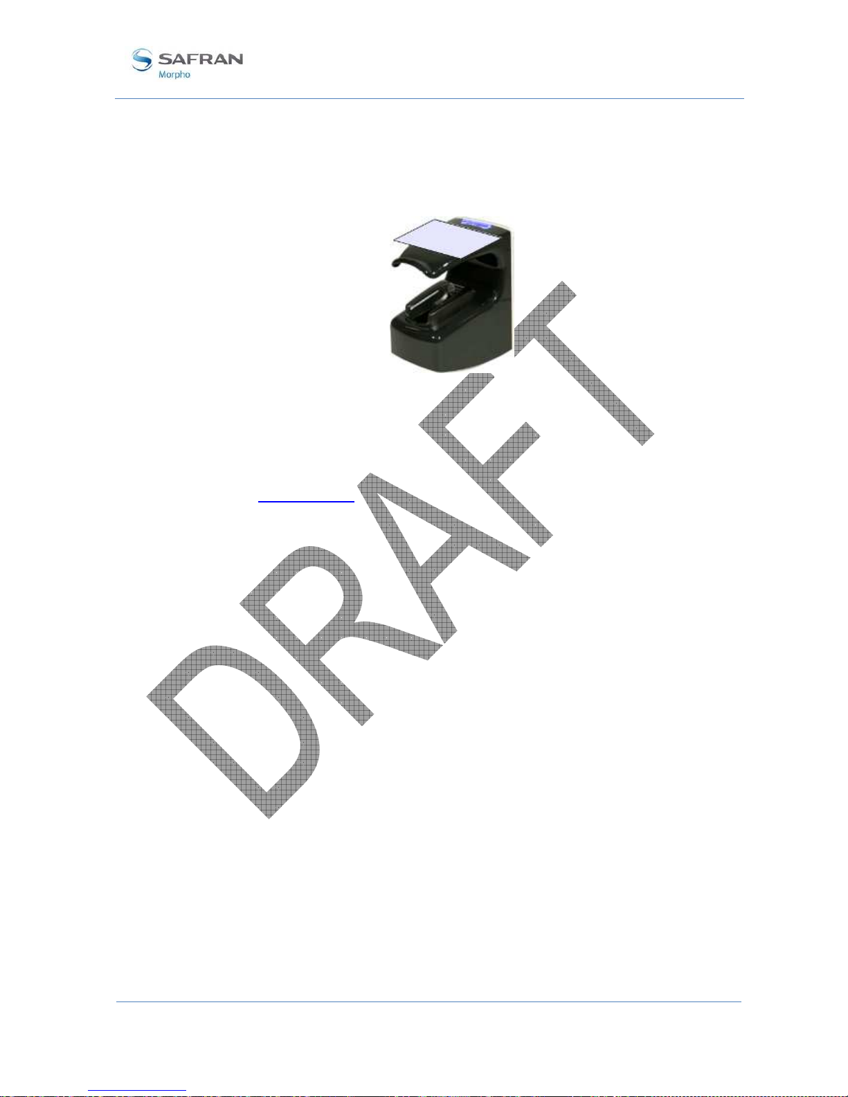
MorphoAccess® VP Series - User Guide
Section 7:
Access control by Authentication
SSE-0000082427-01 M
ORPHO DOCUMENT. REPRODUCTION AND DISCLOSURE PROHIBITED
66
January 2011
User Interface
The authentication process starts when the user presents his contactless card in front of
the terminal.
Figure 27: Authentication without biometric check, and without User ID check
The authentication process succeeds if the user’s identifier is found. Otherwise, the
authentication process fails.
The result of the authentication process is notified to the user by a specific signal, as
described in Terminal states section.
When the authentication process is completed, whatever is the result (identity
confirmed or not), the terminal automatically restarts to the initial state: wait for
another user’s card presentation.

MorphoAccess® VP Series - User Guide
Section 7: Access control by Authentication
67 M
ORPHO DOCUMENT. REPRODUCTION AND DISCLOSURE PROHIBITED
SSE-0000082427-01
January 2011
No biometric check, but User ID check
Description
This authentication mode is the version of the “Biometric check, biometric data in
local database” authentication mode, when biometric check is disabled.
The user’s identifier is the only data read on user’s card. The MorphoAccess®
terminal checks if the user’s identifier exists in the database.
The access is granted if the user’s identifier read on the user’s card is found in the
internal database. Otherwise (user’s identifier not found in the database), the access is
denied.
User’s data required in the terminal
This mode requires a local database, and a record must be created for each allowed
user. Each record contains:
• The same identifier as the one on the user’s card
• The reference biometric data of two fingers of the user.
If the terminal doesn’t found a record with the user’s identifier read on the card, the
access is denied.
The size and the management of the MorphoAccess® terminal internal database is
described in MorphoAccess® Terminal Database management section.
User’s data required on the user’s card
The only data required on the user’s card is the user’s identifier.
The terminal is able to read the user’s identifier either stored according to TLV format
or to be read directly at a given offset on the card (binary format).
All other data found on the card is ignored.
Contactless smartcard logical structure is described in MorphoAccess® Contactless
Card Specification document.
Activation keys
This function requires several configuration keys.
Authentication process without biometric check, but User ID is searched in database
app/bio ctrl/authent ID contactless = 1 Enabled
app/bio ctrl/bypass authentication = 1 Enabled

MorphoAccess® VP Series - User Guide
Section 7:
Access control by Authentication
SSE-0000082427-01 M
ORPHO DOCUMENT. REPRODUCTION AND DISCLOSURE PROHIBITED
68
January 2011
User Interface
The authentication process starts when the user presents his contactless card in front of
the terminal.
Figure 28: Authentication without biometric check, and without User ID check
The user’s identifier is read on the user’s card and searched in the local database.
The authentication process succeeds if the user’s identifier is found in the local
database. Otherwise, the authentication process fails.
The result of the authentication process is notified to the user by a specific signal, as
described in Terminal states section.
Once the authentication process is completed, the terminal automatically loops back
and waits for another user’s card presentation.

MorphoAccess® VP Series - User Guide
Section 7: Access control by Authentication
69 M
ORPHO DOCUMENT. REPRODUCTION AND DISCLOSURE PROHIBITED
SSE-0000082427-01
January 2011
Authentication process specified by User’s card
Description
When this mode is enabled, the access rights check to perform is specified by a
dedicated data on user’s card. It means that the same terminal can execute a different
process according to a data found on the user’s card:
• Either the biometric check is performed with the reference biometric data found
on user’s card
• Or the biometric check is disabled, and only the presence of the user’s identifier
on the user’s card is checked
A card which disables the biometric control is useful when the biometric data capture
is not required (for a short period visitor for example), or impossible (physically or
legally). This kind of cards can be realized without user’s presence and the same card
used for different visitors.
The internal database of the MorphoAccess® terminal is not used.
User’s data required in the terminal
This authentication mode doesn’t use the internal database. There is no personal data
stored in the terminal.
User’s data required on the user’s card
To be compatible with this mode, the user’s card must contain the user’s identifier and
the process selector.
If the biometric check is requested, the biometric data of two fingers of the user must
be present on the user’s card.
All other data are ignored.
The required data must be stored according to TLV format.
Contactless smartcard logical structure is described in MorphoAccess® Contactless
Card Specification document.
Activation key
This mode is activated and deactivated by only one configuration key.
Authentication process defined by user’s contactless card
app/bio ctrl/authent card mode =1 Enabled
app/bio ctrl/authent card mode = 0 Disabled

MorphoAccess® VP Series - User Guide
Section 7:
Access control by Authentication
SSE-0000082427-01 M
ORPHO DOCUMENT. REPRODUCTION AND DISCLOSURE PROHIBITED
70
January 2011
User Interface
Start
The authentication process starts when the user presents his contactless card in front of
the MorphoAccess® terminal.
The terminal searches on the user’s card, for the data that indicates if the biometric
check is mandatory or disabled. If this data is found, the terminal executes the required
process.
Figure 29: Authentication process specified by user's card
Biometric check mandatory
The terminal requires the user to place a finger on the biometric sensor. Then it
executes a biometric comparison of the finger placed on the sensor and the reference
biometric data read on user’s card.
The process is identical to the one described in Biometric check, biometric data on
user’s card section.
Biometric check disabled
The result of the authentication process is positive (identity confirmed), if the user’s
identifier is found on the user’s card.
The terminal doesn’t require the user to place a finger on the biometric sensor, and
doesn’t perform any biometric check.
The process executed in identical to the one described in No biometric check, no user
id check.

MorphoAccess® VP Series - User Guide
Section 7: Access control by Authentication
71 M
ORPHO DOCUMENT. REPRODUCTION AND DISCLOSURE PROHIBITED
SSE-0000082427-01
January 2011
Allowed format for User’s identifier
TLV structured data
The user’s identifier is stored in ASCII within a TLV structure.
User’s identifier stored in TLV format
app/contactless/data format = 0 TLV structure
app/contactless/data length=0.0 Automatic size
app/contactless/data offset= 0.0 Automatic offset
The data written on user’s card by MEMS application, and by MorphoAccess® 500
Series terminals enrolment embedded application, are TLV formatted.
The contactless smartcard logical structure is described in a dedicated document:
MorphoAccess® Contactless Card Specification.

MorphoAccess® VP Series - User Guide
Section 7:
Access control by Authentication
SSE-0000082427-01 M
ORPHO DOCUMENT. REPRODUCTION AND DISCLOSURE PROHIBITED
72
January 2011
ISO14443 type A UID
Description
The MorphoAccess® terminal is able to use the ISO 14443 type A Card UID, as user’s
identifier.
This Card UID is available from any MIFARE™ cards and from any DESFire™
cards.
The Card UID can be read either in most significant byte first (MSB) order, or in less
significant byte (LSB) order.
Card type compatibility
This format can be only used only with the “MIFARE™ only default mode”.
Type of contactless smartcard enabled
app/contactless/enabled profiles = 0 MIFARE™ only (support binary
user’s identifier)
When the key value is 0, the terminal is able to get the card UID of MIFARE™ cards
and DESFire™ cards.
Configuration keys
A configuration key specifies on which kind of identifier the access rights are
assigned. To use Card UID, the CARDDATA tag must be removed, and the
CARDSN:STD or the CARDSN:REV must be added.
app/ bio ctrl/AC_ID
CARDDATA TLV structure: must be removed
CARDSN:STD ISO14443 type A UID, MSB order.
The card UID 0xFEA7B152 value
gives a user’s identifier equal to
4272402770
CARDSN:REV ISO14443 type A UID, LSB order.
The card UID 0xFEA7B152 value
gives a user’s identifier equal to
1387374590.
Another configuration key specifies which kind of user’s identifier starts the access
control process.
Data use for access control request
app/contactless/ event on = 1 ISO 14443 type A Card UID (Unique
IDentifier)

MorphoAccess® VP Series - User Guide
Section 7: Access control by Authentication
73 M
ORPHO DOCUMENT. REPRODUCTION AND DISCLOSURE PROHIBITED
SSE-0000082427-01
January 2011
Binary data
Description
The MorphoAccess® terminal is able to use as user’s identified, a binary value to read
on specific location on user’s card.
This binary value could be the serial number of the card, as explained in the Example:
MIFARE™ card Serial Number used as user’s identifier section.
The MorphoAccess® terminal is able to read a binary value which is not aligned on
complete bytes. This ability is useful to extract the user’s identifier from a Wiegand
frame written on the user’s card. A sample is described in Example: 32 bits user’s
identifier within a 37-bits Wiegand frame section.
No TLV structure is required on user’s card: the MorphoAccess® terminal is able to
use user’s cards written by other systems.
Card type compatibility
This format can be only used only with the “MIFARE™ only default mode”.
Type of contactless smartcard enabled
app/contactless/enabled profiles = 0 MIFARE™ only (support binary
user’s identifier)
Configuration keys
The binary data to read is data defined by:
• The offset of the first block which contains the data
• The offset of the first byte/bit of the data, within the sector (15 bytes maximum).
The terminal is able to read a user’s identifier which offset is different from a
multiple of 8 bits.
• The length (in bytes and bits) of the data (8 bytes maximum). The terminal is able
to read a user’s identifier which length is different from a multiple of 8 bits.
• The read direction (MSB or LSB)
User’s identifier stored in ASCII format
app/contactless/dataformat = 1 Binary format
app/contactless/B [1-215] First block to read on card
app/contactless/data length [number of
bytes].[additional bits]
User ID length in bytes and additional
bits (8 bytes maximum)
app/contactless/data offset [number of Location of first byte/bit of the user’s

SSE-0000082427-01 M
ORPHO
DOCUMENT
January 2011
bytes].[additional bits]
app/contactless/data type
Example:
MIFARE™ card Serial Number used as user’s identifier
In this sample the terminal read the first four byte, in MSB direction, of the first sector
of the MIFARE™ card which contains the serial number of the card.
If bytes to read
are
(ASCII).
Activation of identification mode
app/contactless/data format= 1
app/contactless/data type= 0.1
app/contactless/data length = 4.0
app/contactless/data offset= 0.0
app/contactless/B= 1
Example:
32 bits user’s identifier
The user’s
card contains
(which includes
start and stop
Figure 30 : S
ample of user’s identifier which is
The 32 bits
identifier begins at bit four. It is located after the start bit (bit0) and the site
code (bit1-2-
3). The first block of sector #15 is block #46.
Acquisition of a 32 bits user’s identifier inside a 37 bits Wiegand frame
app/contactless/data format= 1
app/contactless/data type= 0.1
MorphoAccess® VP Series
Section 7:
Access control by Authentication
. R
EPRODUCTION AND DISCLOSURE PROHIBITED
identifier (15 bytes maximum)
Byte read
acquisition
little or big endian.
0.1 (binary data, MSB first)
0.0 (binary data,
LSB first)
F4 E1 65 34, then the user identifier
value
Binary format
Binary MSB format
Size = 4 bytes, no
additional bit
First byte of the block
First block of the card
within a 37-bits
Wiegand frame
, at the first block of sector 15 a full
37 bits Wiegand frame
bits, the site code of the sender
, and user’s identifier
included in a
Wiegand frame
Binary format
Binary identifier, MSB format
- User Guide
74
method: either
is "4108412212"
).
.

MorphoAccess® VP Series - User Guide
Section 7: Access control by Authentication
75 M
ORPHO DOCUMENT. REPRODUCTION AND DISCLOSURE PROHIBITED
SSE-0000082427-01
January 2011
app/contactless/data length = 4.0 Size = 4 bytes
app/contactless/data offset = 0.4 User’s identifier begins at bit 4 of the
first byte of the block specified below
app/contactless/B = 46 Read at block #46 (first block of
sector #15)
It is possible to configure the MorphoAccess® terminal to add automatically the start
and stop bits to the Wiegand output frame, if the user’s identifier must be send to a
distant system using Wiegand protocol.

MorphoAccess® VP Series - User Guide
Section 8:
Multi-factor mode
SSE-0000082427-01 M
ORPHO DOCUMENT. REPRODUCTION AND DISCLOSURE PROHIBITED
76
January 2011
Section 8: Multi-factor mode

MorphoAccess® VP Series - User Guide
Section 8: Multi-factor mode
77 M
ORPHO DOCUMENT. REPRODUCTION AND DISCLOSURE PROHIBITED
SSE-0000082427-01
January 2011
Multi-factor mode
Description
When the identification mode and one of the contactless card authentication modes are
activated, then the terminal is in “multi-factor” mode.
User Interface
It means that the user is allowed to choose the access right control to be processed by
the terminal:
• If the user places his finger first on the sensor, then it is identification process
which is executed.
• If the user presents his contactless card first, then it is authentication process
which is executed.
Figure 31: Multi-factor mode (identification and authentication)
When there is no database, the identification mode is disabled, but the authentication
mode is still available.
User’s data required in the terminal
The requirements of the Identification mode and the requirements of the selected
authentication mode apply to le multi-factor modes.
User’s data required on the user’s card
The items required on the user’s card depend on the authentication mode(s) activated.
Please refer to the appropriate section for further details.
Activation keys
This mode is activated by enabling identification mode, and one of the authentication
modes with contactless card.

MorphoAccess® VP Series - User Guide
Section 8:
Multi-factor mode
SSE-0000082427-01 M
ORPHO DOCUMENT. REPRODUCTION AND DISCLOSURE PROHIBITED
78
January 2011
Activation of multi-factor mode
app/bio ctrl/identification =1 Enabled
app/bio ctrl/authent card mode = 1
or
app/bio ctrl/authent ID contactless = 1
or
app/bio ctrl/authent PK contactless = 1
Enabled
Enabled
Enabled
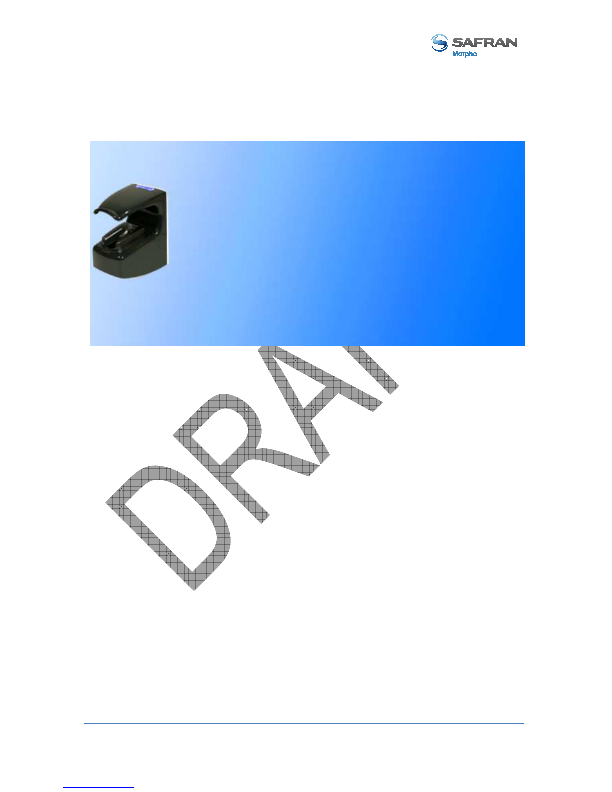
MorphoAccess® VP Series - User Guide
Section 9: Proxy (or slave) Mode
79 M
ORPHO DOCUMENT. REPRODUCTION AND DISCLOSURE PROHIBITED
SSE-0000082427-01
January 2011
Section 9: Proxy (or slave) Mode

MorphoAccess® VP Series - User Guide
Section 9:
Proxy (or slave) Mode
SSE-0000082427-01 M
ORPHO DOCUMENT. REPRODUCTION AND DISCLOSURE PROHIBITED
80
January 2011
Description
Scope
The Proxy mode is an operating mode where the access control main application is
located in a distant system. This is not a standalone mode like Identification and
Authentication modes.
It means that the terminal becomes a slave of the host system application. The access
control application is running on the host system and used MorphoAccess® terminal
high level functions:
• Identification function
• Authentication function
• Read data on a contactless card
• Access control result signal command
Figure 32: Proxy (slave) mode
The MorphoAccess® VP Series terminal is driven through an Ethernet (or Wi-Fi™)
link using TCP or SSL protocol.
The MorphoAccess® terminal acts as a server: it is either waiting for a command or
executing a command.
The commands allowed by the MorphoAccess® terminal are described in the
MorphoAccess® Host System Interface Specification document.
For further details about SSL on the MorphoAccess® terminal, please refer to the SSL
Solution for MorphoAccess® documentation.

MorphoAccess® VP Series - User Guide
Section 9: Proxy (or slave) Mode
81 M
ORPHO DOCUMENT. REPRODUCTION AND DISCLOSURE PROHIBITED
SSE-0000082427-01
January 2011
Local signals
When the terminal is waiting for a command from the distant system, there is none
local signal: the status LED is off, the sensor backlight is off, the buzzer is off.
But when a command is in progress the terminal emits the signals related to the
function. It is the same signals as the standalone modes.
It means, for example, that:
• When the Identify command is in progress, the terminal displays the same signals
as the standalone Identification mode.
• When the terminal receives the “access granted” command from the distant
system, it emits the “access granted” signal as described in the Access control
result section.
The local signals are described in the Section 12 MorphoAccess® VP Series terminal
sound and light Interface section.
Proxy mode use sample
The sample below described a typical exchange between the terminal and the distant
system for a basic access control by identification driven by the distant system.
Figure 33: PROXY sample with a remote Identification process

MorphoAccess® VP Series - User Guide
Section 9:
Proxy (or slave) Mode
SSE-0000082427-01 M
ORPHO DOCUMENT. REPRODUCTION AND DISCLOSURE PROHIBITED
82
January 2011
Proxy mode activation
The proxy mode is automatically enabled when the identification mode and all
authentication modes are disabled.
Proxy mode (all local standalone access control application are inhibited)
app/bio ctrl/identification = 0 Disabled
app/bio ctrl/authent card mode = 0 Disabled
app/bio ctrl/authent PK contactless = 0 Disabled
app/bio ctrl/authent ID contactless = 0 Disabled

MorphoAccess® VP Series - User Guide
Section 10: MorphoAccess® Terminal Customization
83 M
ORPHO DOCUMENT. REPRODUCTION AND DISCLOSURE PROHIBITED
SSE-0000082427-01
January 2011
Section 10: MorphoAccess® Terminal
Customization

MorphoAccess® VP Series - User Guide
Section 10:
MorphoAccess® Terminal Customization
SSE-0000082427-01 M
ORPHO DOCUMENT. REPRODUCTION AND DISCLOSURE PROHIBITED
84
January 2011
Number of biometric check attempts
Description
In order to reduce the False Rejection Rare, the terminal allows the user to place again
his finger on the sensor for a 2nd try, when the initial biometric check fails.
This 2nd try is allowed by default, but can be disabled.
The 2nd try allows the user to upgrade the finger placement, or to place another finger.
In addition, and also to reduce the FRR, during this 2nd try, the terminal executes a
more powerful biometric check (which is also little bit slower).
Configuration key
By default, the two attempts mode is activated, but can be disabled.
Setting up the number of biometric check attempts
app/bio ctrl/nb attempts = 1 Only one, no retry allowed
app/bio ctrl/nb attempts = 2 Two, one 2nd try is allowed (default)
Identification mode
If the finger of the user is not recognized, he has 5 seconds to place again one of his
fingers on the sensor. If a finger is placed on the sensor after this delay, then the
terminal process it as a new access request.
The value of this delay is defined by a dedicated configuration key.
setting up the identification timeout
app/bio ctrl/identification timeout 5 (1-60)
Authentication mode
In authentication mode, if the user place on a sensor a finger which is not recognized,
then the terminal request him to replace his finger without presenting his card again.
The result is sent only after this second attempt.
The wait delay for a finger on the sensor is specified by one configuration key.
Setting up the authentication timeout (seconds)
app/bio ctrl/authent timeout 10 (1-60)

MorphoAccess® VP Series - User Guide
Section 10: MorphoAccess® Terminal Customization
85 M
ORPHO DOCUMENT. REPRODUCTION AND DISCLOSURE PROHIBITED
SSE-0000082427-01
January 2011
Setting up matching threshold
Description
The performances of a biometric system are mainly characterized by two values:
• The False Reject Ratio (FRR) : number of wrongly rejected allowed users, divided
by the number of access requests
• The False Acceptance Ratio (FAR) : number of wrongly admitted not allowed
users, divided by the number of access requests
Both ratio values are linked. Different trade-offs are possible between FRR and FAR
depending on the security level targeted. When convenience is the most important
factor, the FAR must be low and conversely if security is more important, then the
FAR has to be minimized.
Different tunings are proposed in the MorphoAccess® terminal depending on the
security level targeted by the access control system.
Configuration key
The False Acceptance Ratio is tuned indirectly by a configuration key: the highest is
the configuration key value; the lower is the FRR value.
Setting up the matching threshold
bio/bio ctrl/matching th 3 (1-10)

MorphoAccess® VP Series - User Guide
Section 10:
MorphoAccess® Terminal Customization
SSE-0000082427-01 M
ORPHO DOCUMENT. REPRODUCTION AND DISCLOSURE PROHIBITED
86
January 2011
Matching threshold values are detailed in the table below:
Value FAR value
0
Lowest threshold value: the number of false rejects is very low, but
the number of false acceptances is too high for a secure usage.
It is strongly advised to don’t use this value, because the terminal
becomes too tolerant.
1
FAR < 1 %
2
FAR < 0.5 %
3 FAR < 0.1%
Recommended value for physical access control application
4
FAR < 0.05 %
5
FAR < 0.01 %
Recommended value for logical access control application
6
FAR < 0.001 %
7
FAR < 0.0001 %
8
FAR < 0.00001 %
9
FAR < 0.0000001 %
10
Highest threshold value: the number of false acceptance is very
low, but the number of false rejections is too high for the comfort
of users.
It is strongly advised to don’t use this value, because the terminal
becomes too restrictive.

MorphoAccess® VP Series - User Guide
Section 10: MorphoAccess® Terminal Customization
87 M
ORPHO DOCUMENT. REPRODUCTION AND DISCLOSURE PROHIBITED
SSE-0000082427-01
January 2011
Anti-tamper and anti-pulling switches
Description
The MorphoAccess® VP Series terminal is able to detect two kinds of unusual events:
• the front glass is removed, by monitoring anti-tamper switches
• the terminal is removed from the wall, by monitoring the anti-pulling switches
When one of those events is detected, the MorphoAccess® VP Series terminal acts as
required by the related configuration key (see section below):
• Ignore the event (default) : useful during normal maintenance operations
• Send an alarm message to a distant system through the channel already used by
the access control result messages (see Sending the access control result to a
distant system section).
• Emits a local audible and visual signal (see Terminal states section)
The format of the alarm message is described in the MorphoAccess® Remote
Messages Specification document.
Figure 34: Anti-pulling switches
Figure 35: Anti-tamper switches

MorphoAccess® VP Series - User Guide
Section 10:
MorphoAccess® Terminal Customization
SSE-0000082427-01 M
ORPHO DOCUMENT. REPRODUCTION AND DISCLOSURE PROHIBITED
88
January 2011
Please refer to the MorphoAccess® VP Series Installation Guide for more information
about the anti-tamper and the anti-pulling switches.
Configuration keys
The action(s) to be performed by the MorphoAccess® terminal is defined by a unique
dedicated configuration key.
Tamper alarm level
app/tamper alarm/level = 0 Disabled: Anti-pulling and anti-tamper switches are
ignored (default)
app/tamper alarm/level = 1 Silent message only: an alarm message is sent to a
distant system.
app/tamper alarm/level = 2 Silent message and local alarm signal: in addition
to previous level (1), the terminal buzzer emits an
audible and visible alarm signal
The alarm message is sent through the same channel as the “access control result”
message. Then, if there is no channel defined for the result message, the alarm
message is not sent. Please refer to Sending the access control result to a distant system
section.
In addition if the alarm message is to be sent through the serial port using Wiegand or
DataClock protocol, it is mandatory to:
• Enable the sending of error messages.
• Change the error code of the message is default value cannot be used
Allows the sending of error messages (DataClock/Wiegand protocol)
app/failure ID/enabled=1 Enables error message
Anti-pulling or anti-tamper alarm message identifier (Wiegand or DataClock)
app/failure ID/alarm ID 65535 (0 – 65535)

MorphoAccess® VP Series - User Guide
Section 10: MorphoAccess® Terminal Customization
89 M
ORPHO DOCUMENT. REPRODUCTION AND DISCLOSURE PROHIBITED
SSE-0000082427-01
January 2011
Example 1: send alarm message in Wiegand, and output local alarm signal
In case of anti-tamper or anti-pulling detection, the terminal must:
• Send an alarm message to a distant system, using Wiegand protocol. The identifier
(error code) of the alarm message is 62221.
• Emit a local alarm signal.
Send an alarm message in UDP quietly in case of intrusion detection
app/tamper alarm/level = 2 Anti-pulling or anti-tamper: the
terminal output a local alarm signal and
send an alarm message to a distant
system
app/failure ID/alarm ID = 62221 The identifier of alarm message is
62221.
app/failure ID/enabled = 1 Error and alarm messages are allowed
while using Wiegand or DataClock
protocols.
app/send ID wiegand/enabled = 1 Enables to send message though serial
channel using Wiegand protocol.
Example 2: send an alarm message in UDP (no local alarm signal).
In case of anti-tamper or anti-pulling detection, the terminal should send an alarm
message to a distant system, through Ethernet (or Wi-Fi™), using UDP protocol. No
local alarm signal is required.
Send an alarm message in UDP in case of anti-pulling or anti-tamper detection
app/tamper alarm/level = 1 Anti-tamper or anti-pulling : send an
alarm message to a distant system only
(no alarm signal emitted by the
terminal)
app/send ID UDP/enabled =1 Enables message sending though
Ethernet (or Wi-Fi™) channel using
UDP protocol.

MorphoAccess® VP Series - User Guide
Section 10:
MorphoAccess® Terminal Customization
SSE-0000082427-01 M
ORPHO DOCUMENT. REPRODUCTION AND DISCLOSURE PROHIBITED
90
January 2011
Multimodal Security level
Description
The MorphoAccess® VP Series terminals allow to select the security level of the
multimodal biometrics.
Configuration key
The multimodal biometrics security level is selected by only one configuration key.
Multimodal biometrics security level
app/bio ctrl/security level = 0 Standard security level (default value)
app/bio ctrl/security level = 1 High security level.
To be use to increase the protection
against fraud (but it may affect the FRR
and response time)

MorphoAccess® VP Series - User Guide
Section 11: Compatibility with an Access Control System
91 M
ORPHO DOCUMENT. REPRODUCTION AND DISCLOSURE PROHIBITED
SSE-0000082427-01
January 2011
Section 11: Compatibility with an Access Control
System

MorphoAccess® VP Series - User Guide
Section 11:
Compatibility with an Access Control System
SSE-0000082427-01 M
ORPHO DOCUMENT. REPRODUCTION AND DISCLOSURE PROHIBITED
92
January 2011
Internal Relay activation on Access Granted result
Description
If the result of the access rights check is successful, the internal relay may be
optionally activated, for example, to directly trigger a door switch.
The duration of the activation of the internal relay can be modified by a specific
configuration key.
Access control installation using internal relay offers a lower security level, than an
installation with a central access controller which is the only one allowed opening the
door.
Figure 36: MorphoAccess® terminal internal relay
Activation key
A configuration key enables internal relay activation on access granted.
Relay activation when access is granted
app/relay/enabled = 0 Enabled
app/relay/enabled = 1 Disabled
Configuration keys
The relay aperture time can be defined by a specific configuration key (300 means 3
seconds).
Relay aperture time in 10 ms
app/relay/aperture time in 10 ms 300 (50 to 60000)

MorphoAccess® VP Series - User Guide
Section 11: Compatibility with an Access Control System
93 M
ORPHO DOCUMENT. REPRODUCTION AND DISCLOSURE PROHIBITED
SSE-0000082427-01
January 2011
The default state of the relay can also be defined.
Relay default state
app/relay/relay default state = 0 Open (default)
app/relay/relay default state =1 Close

MorphoAccess® VP Series - User Guide
Section 11:
Compatibility with an Access Control System
SSE-0000082427-01 M
ORPHO DOCUMENT. REPRODUCTION AND DISCLOSURE PROHIBITED
94
January 2011
Internal Relay activation by external button
Description
This feature enables to activate the internal relay of the MorphoAccess® terminal
using the LED1 signal input, in addition to normal activation on access granted result.
It means either a successful recognition or a signal on LED1 activate the internal relay.
A typical application of this feature is to open the door from inside an area protected
by a MorphoAccess® terminal (as described in figure below).
• To enter in the building the user must be successfully recognized by the
MorphoAccess® terminal
• A simple push-button connected to LED1 between LED1 and GND wires of the
MorphoAccess® terminal will trigger the door to leave the building.
Figure 37: Activation of internal relay by an external button (sample)
Activation key
A specific configuration key enables this feature.
MorphoAccess® terminal relay is controlled by LED1 input
app/relay/external control by LED1 = 0 Disabled (default)
app/relay/external control by LED1 =1 Enabled

MorphoAccess® VP Series - User Guide
Section 11: Compatibility with an Access Control System
95 M
ORPHO DOCUMENT. REPRODUCTION AND DISCLOSURE PROHIBITED
SSE-0000082427-01
January 2011
Access request result log file
Description
When enabled, the terminal creates a record for each access request in a local log file.
Each record includes:
• the date and the time of record creation (when access control result is known),
• the user’s identifier (if available)
• the access control process executed (Identification, Authentication with biometric
check, ..)
• the result of the access control (granted or denied, and if denied for which reason),
• And other data used for statistical reasons
The format of a log record is described in the MorphoAccess® Host System Interface
Specification document.
Log File management
Three commands are available for log file management:
• A command which return the current status of the log feature (enabled/disabled,
number of records)
• A command which returns the content of the log file
• A command that delete the log file
For more information about these commands, refer to the MorphoAccess® Host
System Interface Specification document.
Log File size
The capacity of the log file is 8 000 records.
When the log file is full, the terminal automatically stops the addition of new records,
but new access requests are allowed.
If requested by the specific configuration keys, the terminal can sent a “log file full”
warning message to a distant system.
The format of the “Log file full warning” message is described in the MorphoAccess®
Remote Messages Specification document.

MorphoAccess® VP Series - User Guide
Section 11:
Compatibility with an Access Control System
SSE-0000082427-01 M
ORPHO DOCUMENT. REPRODUCTION AND DISCLOSURE PROHIBITED
96
January 2011
Activation key
The creation of a record for each access request is enabled (and disabled), by only one
configuration key.
Enabling recording of all access request results in the internal log file
app/log file/enabled = 1 Enabled
app/log file/enabled = 0 Disabled

MorphoAccess® VP Series - User Guide
Section 11: Compatibility with an Access Control System
97 M
ORPHO DOCUMENT. REPRODUCTION AND DISCLOSURE PROHIBITED
SSE-0000082427-01
January 2011
Sending the access control result to a distant system
Presentation
After access control rights check, the MorphoAccess® terminal can send a message
which contains the result of the control, to a distant device (such as a Central Security
Controller). The MorphoAccess® terminal is able to use different channels and
different protocols, to send this message.
This message can be used, for instance, to log the access request or to perform
additional access rights check. It depends on the role of the distant device in the global
access control system.
Figure 38: Sending access control result message to a distant system
Please refer to MorphoAccess® Remote Messages Specification for more information
about the format and the protocol of the access control result messages.
The LED IN feature enables to expect a positive answer from the distant system before
granting the access.
Available ports and protocols
The MorphoAccess® VP Series terminal is able to send the access control result
messages to a distant system, using the following ports and protocols:
• serial port : Wiegand or DataClock, or RS485
• Ethernet link or Wi-Fi™ link: TCP or UDP or SSL
This is detailed in the next sections.
Serial port (output only)
Protocol selection
There is only one serial port, and then only one protocol can be used. It must be one of
these protocols: Wiegand or DataClock or RS485.

MorphoAccess® VP Series - User Guide
Section 11:
Compatibility with an Access Control System
SSE-0000082427-01 M
ORPHO DOCUMENT. REPRODUCTION AND DISCLOSURE PROHIBITED
98
January 2011
Wiegand protocol
The Wiegand frame includes only the user identifier (which must be a numeric value).
By default, the access control result message is sent only when the user is identified or
authenticated.
But as an option this access control result message can be sent when the access is
denied, but with a numeric error code instead of the user identifier value.
The sending of the message through the serial port, using DataClock protocol is
conditioned only one configuration keys.
Send access control result message using Wiegand protocol on serial output port
app/send ID wiegand/enabled = 1 Enabled
app/send ID wiegand/enabled = 0 Disabled
The format of the Wiegand frame is defined by several configuration keys.
DataClock protocol
Same comment as for Wiegand protocol.
The sending of the message through the serial port, using DataClock protocol is
conditioned only one configuration keys.
Send access control result message using DataClock protocol on serial output
port
app/send ID dataclock /enabled = 1 Enabled
app/send ID dataclock /enabled = 0 Disabled
RS485 protocol
The message is send whatever is the control result, and it contains more information
than the Wiegand and the DataClock frames.
The message format (ASCII characters) includes the user identifier, but also the result
of the control, the date and time of the access request, and other data.
The sending of the message through the serial port, using RS484 protocol is
conditioned to two configuration keys.
Send access control result message using RS485 protocol on serial output port
app/send ID serial /enabled = 1 Enabled
app/send ID serial /enabled = 0 Disabled
app/send ID serial/mode = 485 RS485 protocol

MorphoAccess® VP Series - User Guide
Section 11: Compatibility with an Access Control System
99 M
ORPHO DOCUMENT. REPRODUCTION AND DISCLOSURE PROHIBITED
SSE-0000082427-01
January 2011
Ethernet port
Protocol selection
The protocol used to send the message through the Ethernet link, must be only one of
these protocols: UDP or TCP or SSL.
UDP protocol
Same comment as for RS485 protocol.
Send access control result message using UDP protocol on Ethernet port
app/send ID UDP/enabled = 1 Enabled
app/send ID UDP /enabled = 0 Disabled
TCP protocol
Same comment as for RS485 protocol.
Send access control result message using TCP protocol on Ethernet port
app/send ID ethernet /mode = 0 Disabled
app/send ID ethernet /mode = 1 UDP
app/send ID ethernet /mode = 2 TCP
SSL protocol
For details about SSL protocol, please refer to SSL Solution for MorphoAccess®
document.
Wi-Fi™ channel
Instead of Ethernet connection, the terminal can be connected using a wireless Wi-Fi™
b/g connection. Please refer to Wi-Fi™ Network configuration section for more
information.
The message format and the protocols supported are the same as the Ethernet channel:
UDP, or TCP or SSL.
Warning: it is not possible for a terminal to be connected through Ethernet and
through Wi-Fi™ at the same time.

MorphoAccess® VP Series - User Guide
Section 11:
Compatibility with an Access Control System
SSE-0000082427-01 M
ORPHO DOCUMENT. REPRODUCTION AND DISCLOSURE PROHIBITED
100
January 2011
Note about terminal clock deviation
The message send through IP and RS485 includes the date/time of access control
result. The terminal clock has a +/- 4 sec per day typical time deviation at +25°C.
At 50°C, the time deviation may be up to -8 sec per day.
For features that requiring time precision (such as SSL protocol or DESFire™
contactless card), the clock of the MorphoAccess® terminal must be synchronized
regularly with an external clock (using the appropriated ILV command).
 Loading...