

Safire 3200B, 3800A Installation, Operation And Maintenance Manual
SAFIRE 3200B AND 3800A FUEL OIL HEATER
INSTALLATION, OPERATION AND MAINTENANCE
You have selected the new generation SAFIRE oil heater as your heating solution.
Although our goal is to take into account all problems arising from normal installation during designing the
product, it is important that persons using this product familiarise themselves with these instructions.
Correct installation and use ensure that the heater works flawlessly for many years to come.
1. INSTALLATION
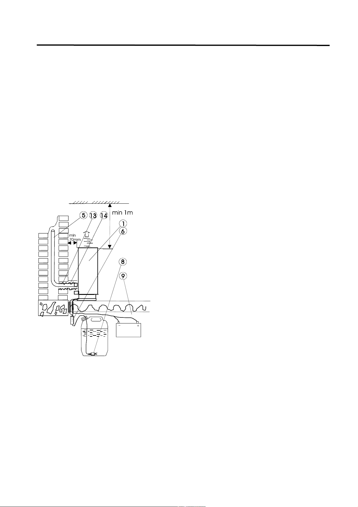
1.2 PLACEMENT
Place the heater so that warm air circulates in the best possible way in the heated space.
Flue gases can be led to a chimney or directly out through the wall.
The heater should preferably be connected directly to the battery with a dedicated power
cable.
The tank and pump should be placed under the heater. It is advisable to place them outside
the heated space.
There should be 70-100 mm clearance behind and on the sides of the heater in order to help
keep its environment clean and free from foreign objects.
There must be at least one metre of clearance above the heater.
1.3 DUCT INSTALLATION
1. Drill a suitably sized hole for the flue gas pipe to the chimney. Note that the flue gas pipe is not
laterally in the centre of the heater.
2. Seal the flue gas pipe into place with heat-resistant material (e.g. mineral wool or mortar). The flue
gas pipe must lead to the top of the chimney, and it should preferably be insulated with vermiculite.
This will avoid the condensation of the flue gas in the cold chimney, as well as failures and weathering
of the chimney resulting from the condensation.
3. Install a piece of thermal insulation cut to a suitable length.
4. Mount the heater and tighten the flue gas pipe and a potential air intake pipe with their fasteners.
5. The combustion air can be led to the heater e.g. from under the floor. In this case, the air intake must
be protected so that it cannot be clogged (snow, leaves, mice, birds, mosquitoes etc.). The intake pipe
must be insulated indoors in order to prevent condensation on the surface of the pipe.
December 2014
SF-LÄMMITIN OY Tilhenkatu 1 20610 Turku Finland Tel./Fax 02-2443282
1. HEATER 9. BATTERY
5. FLUE GAS PIPE 13. SEALING
6. PUMP 14. THERMAL INSULATION
8. FILTER
When using a chimney, the combustion air can be
taken from the outside or inside, because there is no
danger of flue gas returning to the inside air due to the
wind pressure, even in case of a power outage.
As the combustion air is taken from the heated space,
the heater functions as a ventilation unit as well, which
reduces the amount of moisture.
It is preferable that the tank is placed outside the
heated space. However, the tank and the pump must
be placed under the bottom of the heater. The lifting
height must be under 2 metres.
If the fuel line is mounted inside the structures or
outside the building, it must be protected with e.g.
electric installation pipe or metal pipe.
A longer fuel line can be used, but the maximum length
between the pump and the fuel tank is 6 metres.

SAFIRE 3200B AND 3800A FUEL OIL HEATER
INSTALLATION, OPERATION AND MAINTENANCE
WALL SLEEVE INSTALLATION
WALL SLEEVE:
When using wall sleeves, the combustion air must be led through a wall sleeve from the outside as well.
1.5 TANK, TANK CONNECTION, PUMP
December 2014
SF-LÄMMITIN OY Tilhenkatu 1 20610 Turku Finland Tel./Fax 02-2443282
1 HEATER
2 THERMOSTAT TEMPERATURE SENSOR
3 FLUE GAS PIPE
6 PUMP
7 TANK
8 FILTER
9 BATTERY
12 FLUE GAS WALL SLEEVE
14 THERMAL INSULATION
1. Make a ø90 mm hole to the wall, whose
midpoint is at a height of 225 millimetres from the
bottom of the heater.
2. Stretch the air pipe (2) in accordance with
the wall thickness, and install it.
3. Attach the interface box (3). Flue gas pipe
height: midpoint 225 mm from the bottom of the
heater.
4. Cut the vent pipe (4) to a suitable length and
fasten it with a clamp (12).
5. Install the overlong flue gas pipe (5) with a
fastener (6).
6. Install thermal insulation (7) of suitable length
around the flue gas pipe.
7. Mount the heater.
8. Remove the housing (10) and diffuser (9) from
the frame of the funnel. The housing can be
removed by lifting its upper part approx. 4 mm.
Attach the frame (8) of the funnel to the wall. Seal
with silicone compound in order to keep water
outside the wall structures. Fasten the topmost
mounting screws (11) temporarily.
9. Cut the flue gas pipe to a suitable size (see
drawing: 12 mm out of the funnel frame)
10. Mount the diffuser (9) of the funnel and the
housing (10). You will have to loosen the topmost
mounting screws for this.
SAFIRE 3200B AND 3800A FUEL OIL HEATER
INSTALLATION, OPERATION AND MAINTENANCE
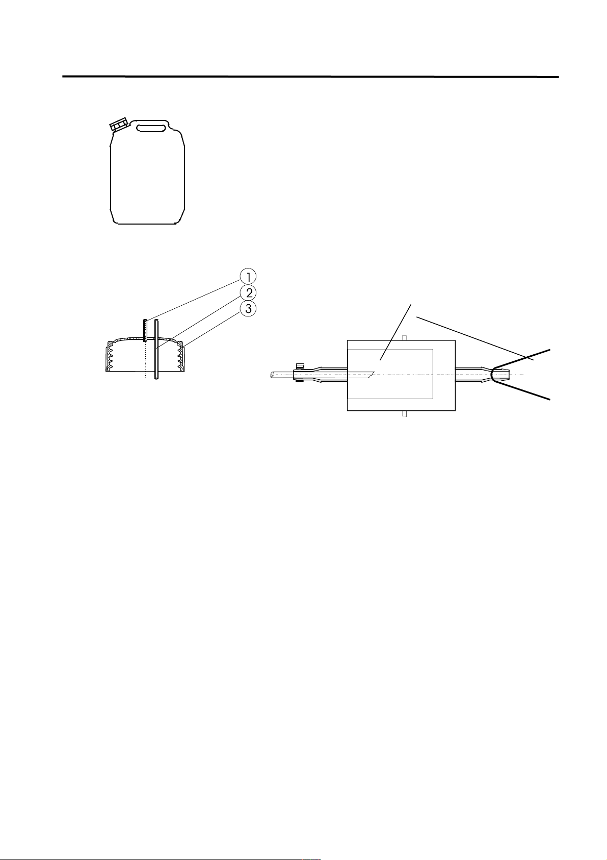
1.5.1 30L TANK (475x315x295mm)
Can be used either upright or horizontally.
The heater comes with tank connection parts (filter, vacuum hose, air hose and
threaded ring).
The tank must be placed under the heater, e.g. in the basement of the house.
If the fuel line and wiring of the pump have to be led through the structures, they
must be protected with e.g. electric plastic installation pipe. For trought the floor
or wall, drill approx. 10 mm hole for fuel line and wiring.
If you want to install the tank and pump inside, select a place where filling the
tank or exchanging tanks does not cause inconvenience.
1.5.3 TANK CONNECTION
1.5.4 PUMP
The pump is installed close to the tank above the liquid surface in an upright position with the
suction side down. The maximum vertical drop from the bottom of the heater to the tank is
approx. 2 metres.
1.6 ELECTRICAL INSTALLATION (see wiring diagram on the back cover)
.
1. The electricity should preferably be input directly from the battery (+ red, - yellow). Protect
the wiring with a 20 A fuse (the electronics of the heater are protected by a 15 A main fuse).
If you need to use longer wires, remember to replace the original wiring with thicker ones so
that the cross-sectional area of the wires in mm2 corresponds with the length of the wires in
metres, e.g. the area of two 10 metre wires should be at least 10 mm2.
In this case, cut the original wires at a suitable length behind the heater and attach thicker
wires with a suitable connecting piece.
Be careful not to connect the wires to the battery with reverse polarity (in this case, the
fuse of the electronics will blow).
2. The wires of the pump are connected to the middle pins of the X10 connector. The wires
cannot be connected the wrong way round.
3. In thermostat installations the sensor is connected to the empty pins of the X10 connector
(see wiring diagram). The wires can be extended and they cannot be connected the wrong
way round.
4. A Gsm- remote start-up device is connected behind the control panel to the X9 connector of
the heater circuit board.
When using automatic start-up, the heater switch should be in the AUTO position.
The circuit board of the heater has a selection connector for the input voltage of the RJ
connector. It should be in the position 2-3 when a 1287 remote control device is used (this is
the factory default setting) and in position 1-2 if a Genius control board is used.
December 2014
SF-LÄMMITIN OY Tilhenkatu 1 20610 Turku Finland Tel./Fax 02-2443282
1. AIR HOSE
2. FUEL HOSE
3. THREADED RING
4. FILTER
5. PROTECTION
 Loading...