

Safire 2400Di, 2600Di, 3200Di, 3600Di Usage, Installation And Maintenance
SAFIRE 2400Di, 2600Di, 3200Di and 3600Di Diesel / fuel oil heaters
1
USAGE, INSTALLATION AND MAINTENANCE
January 2012
SF - Lämmitin Oy
Tilhenkatu 1 20610 Turku Finland Puh./Fax +358(0)2-2443282
1
!
A heater kit contains:
• Heater, mounting bracket
• Fuel hose (3 meters), pump, a fuel tank connection to a standard tank (30 litres)
• Power supply cable (4 meters), control panel cable (10 meters)
• Mounting screws, clamps
• Accessories indicated on the package: Control panel or GENIUS control panel, temperature sensor for the
thermostat, exhaust outlet through the hull.
PLACING THE HEATER
Place the heater so that at least a part of the air to be warmed can be taken outside. This will allow good
ventilation and drying effect.
When choosing a place for the heater remember that warm air hoses placed outside the heated space will
lose plenty of heat. Minimize their length and isolate them carefully. It is more economic to place the heater
close to the space to be heated and use a separate fresh air inlet. You don’t have to isolate the warm air
hoses inside (f. ex. under the bed); the hoses function as “radiators” for they dry the space and balance the
temperature differences.
Remember also that as the heater blows warm air inside, an equivalent amount of air must be let out f. ex.
through a ventilator or return to the heater as circulating air.
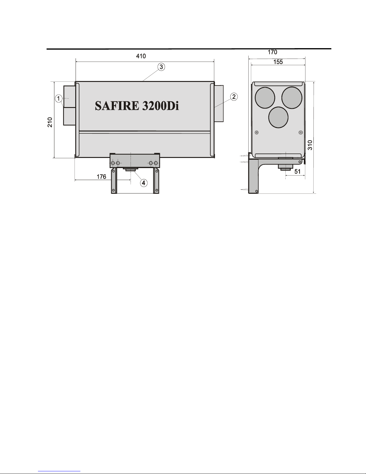
Maintenance is usually easiest to perform when the heater is removed from its bracket. If the heater is
examined on its place, place the heater so that the led indicators near the fresh air inlet and the control
display are in sight.
Place the heater so that the heater is above the tank’s fuel level. The heater will however not be damaged if
the filler hole of the tank and thereby the fuel level temporarily rises above the heater.
The fuel hose can be lengthened between the pump and the tank.
SAFIRE 2400Di, 2600Di, 3200Di and 3600Di Diesel / fuel oil heaters
2
USAGE, INSTALLATION AND MAINTENANCE
January 2012
SF_ Lämmitin Oy Tilhenkatu 1 20610 Turku Finland Puh/Fax +358(0)2-2443282
INSTALLATION
Mounting bracket
Screw the heater’s mounting bracket to its place so that the heater is set in a horizontal position.
Pump and fuel hose
Attach the fuel pump in an upright position close to the fuel tank but above the fuel level, the
suction downwards. Max high between tank and heater 2m. If you need to pass the fuel hose
and the pump’s power supply cable through narrow gaps, disconnect the hose connector
above the pump and unplug the power supply cable from the pump’s connection terminal (the
polarity is insignificant). Attach the fuel hose carefully so that it won’t vibrate or rub against
anything. Don’t attach the pump too tight; this may cause disturbing noise.
Fuel tank connection
The fuel is conducted with a suction hose either from a separate tank (15, 22 or 30 litres) using a suitable
tank connection, or from a diesel tank by using a tank connection kit. Install a shut-off to the tank connection
if the fuel level in the tank or in the fuel hose can rise above the pump. Attach the fuel hoses carefully and
protect them from heat or mechanical strain.
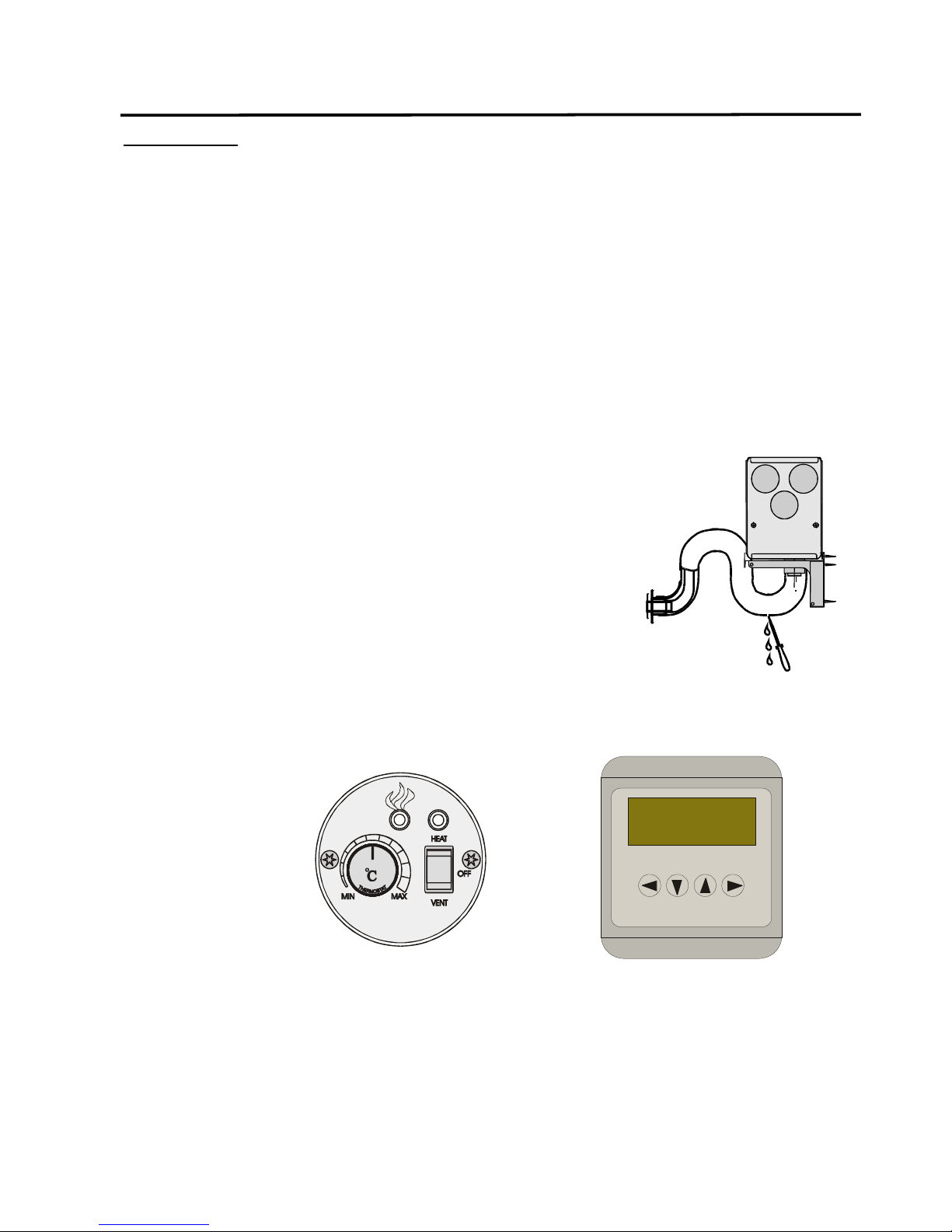
Exhaust outlet
Exhaust is led out and combustion air taken in through hull with a coaxial
exhaust outlet.
For installing the outlet you need to make one Ø 50 mm hole and four 5,5 mm
holes (use the outlet end as a model). Cut the inner pipe a bit too long, so that
it can’t slip from its place. Bend the exhaust outlet hose as shown in the picture
and make a little hole on the outer hose, on the lowest part.
This way the condensation water can trip away.
Max. length of exhaust tube is 2m fir 2400Di, 2600Di and 3200Di and 1,5m for 3600Di.
Thermostat
Place the thermostat’s sensor to a place where it can measure the temperature
in the room in the best way. If you are using a GENIUS control panel, you can
connect two thermostats to the heater; one to be used during the night in the
sleeping cabin and one for the daytime to be used in the front cabin.
Controll panels
SAFIRE 3000
Place the control panel so that the display is easy to see and use, and that there’s no danger of starting the
heater by accident. The basic control panel can be either surface or flush mounted. The GENIUS control
panel is designed to surface mounting only. Attach the control panel to the heater with an included cable.
SAFIRE
BACK
OK
Hallinta
Ajastin
Asetukset
Termostaattinytt
Made in Finland by
SF-Lmmitin Oy
genius
SAFIRE 2400Di, 2600Di 3200Di and 3600Di Diesel / fuel oil heaters
3
USAGE, INSTALLATION AND MAINTENANCE
January 2012
SF - Lämmitin Oy
Tilhenkatu 1 20610 Turku Finland Puh/Fax+358(0)2-2443282
3
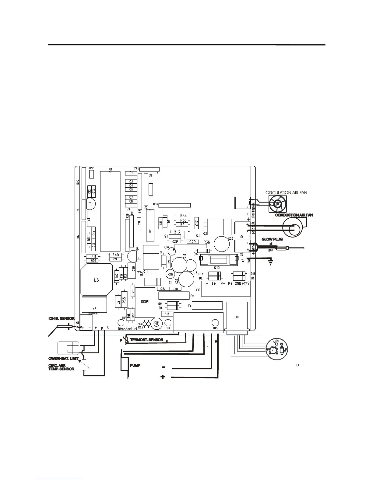
Electric wiring
See the wiring diagram below.
The heater’s power supply cables should be connected straight to the battery (red +, blue -). If you need
longer cables, you should change also the original cables to thicker ones so that the area of the wires (mm2)
corresponds their length (m); f. ex. 6 meter long wires should be entirely at least 6 mm2 thick.
NB! The housing of the heater is galvanic connected to the minus-pole of the battery.
You can connect a separate main switch to the heater and a 20A time delay fuse near the battery (there is a
20A main time delay fuse F1 on the circuit board).
Be careful not to connect the wires wrong. This would melt the 7,5A fuse F2, which protects the electronics.
Connect the thermostat’s sensor to the connector X10.
The system detects automatically the installed thermostat and changes the Power control on the control
panel to Temperature control.
Connect the pump’s power supply cables to the connector X10
.
Fix the cables so that water does not get into the heater among them.
SAFIRE 3000
C
T
H
E
R
M
O
S
T
A
T
"
# $ %&'$ ()*% (
 Loading...