


Installation and Operation Manual
CBX/CB Series
Fixed Frame Top Mount Trailer Air Suspension
For Disc and Drum Brake Applications
XL-AS11406OM-en-US Rev E


Contents
Contents Page
Introduction ......................................................................... 3
Warranty .............................................................................. 3
Notes, Cautions, and Warnings ............................................. 3
Section 1 – General Safety Instructions ................................ 4
Section 2 – Standard Decal Requirements ............................ 5
Section 3 – CBX Fusion Model Identification ....................... 6
Section 4 – CBX Fusion Model Nomenclature ....................... 6
Section 5 – CBX Model Identification ................................... 7
Section 6 – CBX Model Nomenclature .................................. 7
Section 7 – CB-2300 Model Identification ........................... 8
Introduction
This manual provides information necessary for the installation
and operation of the SAF-HOLLAND® CBX/CB fixed frame top
mount trailer air suspension. Although the images throughout
this manual depict the CBX23 Fusion, there is no difference in
fit or function between the models in the CBX/CB Series.
The CBX/CB suspensions include premium 5.75" diameter
axles, the CB suspensions include 5" diameter axles. For axle
end and/or brake servicing information or component
replacements, refer to Drum Brake Manual XL-TA10006OM-en-US,
Disc Brake Manual XL-SA10059OM-en-US or contact Customer
Service at 888-396-6501.
Contents Page
Section 8 – CB-2300 Model Nomenclature ........................... 8
Section 9 – Welding Standards ............................................. 9
Section 10 – Standard Air Control System Installation ........ 10
Section 11 – Suspension Assembly Installation ................... 11
Section 12 – Ride Height Adjustment ................................. 12
Section 13 – SwingAlign™ Axle Alignment .......................... 14
Section 14 – Brake Adjustment Instructions ........................ 14
Section 15 – Pre-Operation Information ............................. 15
Section 16 – Maintenance and Service Schedule................. 16
Section 17 – Torque Specifications ..................................... 17
Warranty
Refer to the complete warranty for the country in which
the product will be used. A copy of the written warranty is
included with the product or available on the internet at
www.safholland.com.
Notes, Cautions, and Warnings
Before starting any work on the unit, read and understand all
the safety procedures presented in this manual. This manual
contains the terms “NOTE”, “IMPORTANT”, “CAUTION”, and
“WARNING” followed by important product information. These
terms are defined as follows:
This suspension uses air drawn from the tractor air system to
pressurize the air springs. The height control valve (HCV) regulates
the air pressure required for varying loads while maintaining the
design ride height. This suspension can provide a cushioned ride
throughout the load range, from empty to fully loaded.
The suspension also provides excellent side-to-side and
axle-to-axle loading which helps equalize and control braking.
Read this manual before using or servicing this product and
keep it in a safe location for future reference. Updates to this
manual, which are published as necessary, are available on
the internet at www.safholland.us.
When replacement parts are required, SAF-HOLLAND
highly recommends the use of only SAF-HOLLAND Original
Parts. A list of technical support locations that supply
SAF-HOLLAND Original Parts and an Aftermarket Parts Catalog
are available on the internet at www.safholland.us
or contact Customer Service at 888-396-6501.
NOTE: Includes additional information to enable accurate
and easy performance of procedures.
IMPORTANT: Includes additional information that
if not followed could lead to hindered
product performance.
Used without the safety alert symbol,
indicates a potentially hazardous
situation which, if not avoided, could
result in property damage.
Indicates a potentially hazardous
situation which, if not avoided, could
result in minor or moderate injury.
Indicates a potentially hazardous
situation which, if not avoided, could
result in death or serious injury.
XL-AS11406OM-en-US Rev E · 2018-04-17 · Amendments and Errors Reserved · © SAF-HOLLAND, Inc., SAF-HOLLAND, HOLLAND, SAF,
and logos are trademarks of SAF-HOLLAND S.A., SAF-HOLLAND GmbH, and SAF-HOLLAND, Inc.
3

General Safety Instructions
1. Safety Instructions
General and Servicing Safety Instructions
Read and observe all Warning and Caution hazard alert
messages. The alerts provide information that can help prevent
serious personal injury, damage to components, or both.
Failure to follow the instructions and
safety precautions in this manual could
result in improper servicing or operation
leading to component failure which, if not
avoided, could result in death or serious injury.
All maintenance should be performed by a properly
technician using proper/special tools, and safe procedures.
NOTE: In the United States, workshop safety requirements
are defined by federal and/or state Occupational
Safety and Health Act (OSHA). Equivalent laws may
exist in other countries. This manual is written based
on the assumption that OSHA or other applicable
employee safety regulations are followed by the
location where work is performed.
Properly support and secure the vehicle from unexpected
movement when servicing the unit.
Failure to properly support and secure the
vehicle and axles prior to commencing work
could create a crush hazard which, if not
avoided, could result in death or serious injury.
If possible, unload the trailer before performing any
service procedures.
After re-positioning the brake chamber, slack adjuster and/
or ABS system as instructed in this manual, always consult
the manufacturer’s manual for proper operation.
Service both roadside and curbside of an axle. Worn parts
should be replaced in sets. Key components on each axle’s
braking system, such as friction material, rotors and drums
will normally wear over time.
Follow all manufacturer’s instructions on spring pressure
and/or air pressure controls.
Failure to follow manufacturer’s instructions
regarding spring pressure or air pressure
control could allow unexpected release of
energy which, if not avoided, could result
in death or serious injury.
DO NOT paint the wheel contact surfaces between the wheel
and hub.
IMPORTANT: The wheel contact surfaces MUST be clean,
smooth and free from grease.
Failure to keep wheel and hub contact surfaces
clean and clear of foreign material could
allow wheel/hub separations which, if not
avoided, could result in death or serious injury.
Only the wheel and tire sizes approved by the trailer builder
can be used.
trained
Operational and Road Safety Instructions
Before operating vehicle, ensure that the maximum permissible
axle load is NOT exceeded and that the load is distributed
equally and uniformly.
Make sure that the brakes are NOT overheated from
continuous operation.
Failure to minimize the use of brakes during
overheating conditions could result in
deterioration of brake efficiency which,
if not avoided, could result in death or
serious injury.
The parking brake MUST NOT be immediately applied when
the brakes are overheated.
If the parking brake is immediately applied
to the brakes when overheated, the brake
drums or discs could be damaged by different
stress fields during cooling.
Observe the operating recommendation of the trailer
manufacturer for off-road operation of the installed axles.
IMPORTANT: The definition of OFF-ROAD means driving
on non-asphalt/non-concrete routes, e.g.
gravel roads, agricultural and forestry tracks,
on construction sites and in gravel pits.
IMPORTANT: Off-road operation of axles beyond
the approved application design could
result in damage and impair suspension
system performance.
Follow the recommended routine maintenance and inspections
described in this manual. These procedures are designed so
that optimum performance and operational safety are achieved.
In the event of suspension air pressure loss, quickly reduce
speed as safely as possible and remove the vehicle from
traffic. If unable to remove vehicle from traffic, follow DOT
safety requirements regarding emergency situations.
Contact a qualified towing and/or service company to assist
in repairing the vehicle or to move it to a qualified repair facility.
DO NOT operate the vehicle in the absence of suspension
air pressure; however in the event of an air system failure
while in service, an internal rubber bumper built into the
air spring will make it possible to temporarily operate the
vehicle at reduced speed determined by road conditions.
Operating the vehicle without proper air
pressure can cause tire failure, fire, or loss
of vehicle control which, if not avoided,
could result in death or serious injury.
4
XL-AS11406OM-en-US Rev E · 2018-04-17 · Amendments and Errors Reserved · © SAF-HOLLAND, Inc., SAF-HOLLAND, HOLLAND, SAF,
and logos are trademarks of SAF-HOLLAND S.A., SAF-HOLLAND GmbH, and SAF-HOLLAND, Inc.
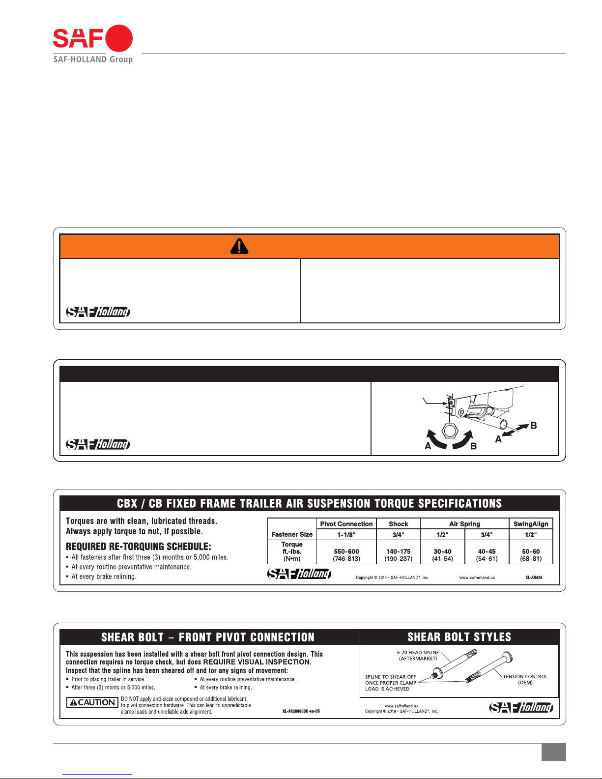
2. Standard Decal Requirements
Decal Requirements
The following three (3) decals MUST be properly installed on
the trailer prior to putting it in service:
It is the responsibility of the end user to periodically inspect
all decals and ensure that they are clean and completely legible.
If any decals are missing, loose, damaged or difficult to read,
Tire Clearance Warning Decal: XL-AR356-01 (Figure 1).
SwingAlign Axle Alignment Decal: XL-AR435 (Figure 2).
Torque Decal: XL-AR436 (Figure 3).
Shear Bolt Decal: XL-AS20085DC-en-US (Figure 4).
contact SAF-HOLLAND Customer Service at 888-396-6501
to order replacements immediately.
Figure 1
WARNING
Minimum tire clearance MUST be maintained between tires and
nearest point of contact on the suspension or vehicle. Premature
tire wear, fire or loss of vehicle control could result from contact
with the tires if clearances are not maintained.
Copyright © 2011 • SAF-HOLLAND, Inc.
www.safholland.us
XL-AR356-01
Figure 2
SWING ALIGN® NON-WELDED AXLE ALIGNMENT PROCEDURES
ALIGNMENT BOLT IS ON THE FRONT OF THE ROADSIDE FRAME BRACKET:
STEP 1. To properly align the suspension, the trailer should be pulled in a straight line for a sufficient distance
to insure there are no binds in the suspension.
STEP 2. Check to verify trailer is empty and emergency brakes are NOT engaged.
STEP 3. Rotate bolt CLOCKWISE to move axle forward (A arrows); COUNTERCLOCKWISE to move axle rearward (B arrows).
Copyright © 2011 • SAF-HOLLAND, Inc.
www.safholland.us
TIRE CLEARANCE REQUIREMENTS
• 1 INCH (25.4 mm) MINIMUM VERTICAL tire clearance is required between the top of the tire
and the nearest point of contact above the tire when the air pressure is completely exhausted
from the air suspension or when the axle is fully lifted if equipped with a suspension lift feature.
• 2 INCH (50.8 mm) MINIMUM LATERAL tire clearance is required between the sides of the
tire and the nearest point of contact through total travel of the air suspension. This includes
when the wheels are fully turned in either direction if equipped with an SAF Self Steer Axle.
XL-AR435 Rev. B
ALIGNMENT BOLT HEAD
NOTE:
1/2 turn of
free play in either
direction (A or B)
is acceptable.
A = axle forward
B = axle rearward
Figure 3
Figure 4
XL-AS11406OM-en-US Rev E · 2018-04-17 · Amendments and Errors Reserved · © SAF-HOLLAND, Inc., SAF-HOLLAND, HOLLAND, SAF,
and logos are trademarks of SAF-HOLLAND S.A., SAF-HOLLAND GmbH, and SAF-HOLLAND, Inc.
5

Model Identification and Nomenclature
24.50"
31.70"
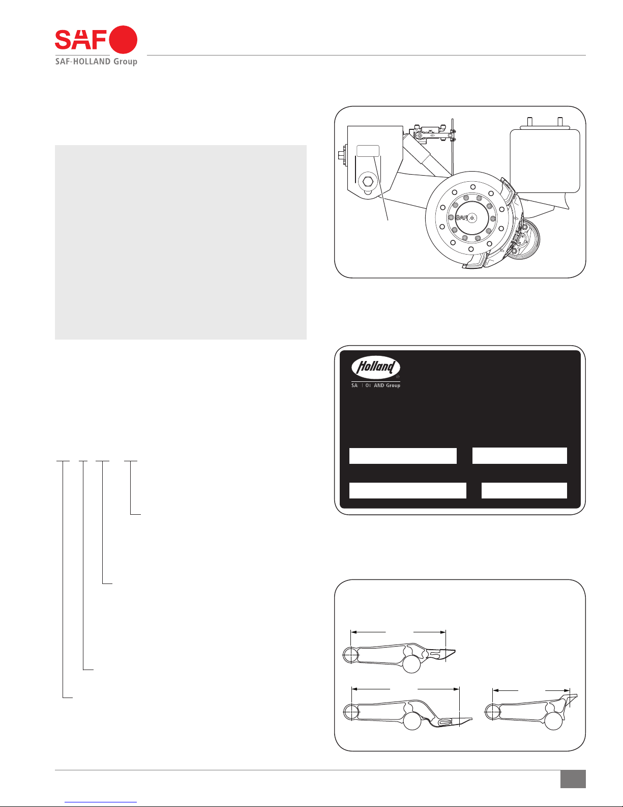
3. CBX Fusion Model Identification
The CBX Fusion suspension serial tag is located on the frame
bracket (Figure 4).
NOTE: This manual applies to the suspension models
listed on the front cover. However, determine the
specific model number, write that information
below and refer to it when obtaining information
or replacement parts (Figure 5).
NOTE: If the suspension serial tag is NOT legible or is
NOT available, it can identified by the appearance
of the equalizing beam (Figure 6). The CBX
Fusion model will have a cast beam with a lower
air spring mounting plate welded to it mounted on
a 5.75" round axle (Figure 6).
NOTE: The CBX Fusion models come in four (4) different
beam lengths. Equalizing beam lengths are
measured from the centerline of the pivot to
the centerline of the air spring mounting plate
(Figure 6).
4. CBX Fusion Model Nomenclature
Figure 4
TAG LOCATED ON
THE FRAME BRACKET
Figure 5
The sample tag illustrated will help interpret the information
on the SAF-HOLLAND, Inc. serial number tag. The part
number is on the first line. The model number along with the
suspension capacity are on the second line. The third line
contains the serial number (Figure 5).
CB X 23 - 14
Ride Height
14" (356 mm)
15" (381 mm)
16" (406 mm)
17" (432 mm)
Axle Capacity
Suspension Series
20 – 20,000
23 – 23,000
25 – 25,000
25/30 – 25,000/30,000*
*30,000 at creep speed
5.75" Diameter Premium Axle
Cast Beam Suspension
Figure 6
CBX FUSION BEAM LENGTH OPTIONS
33.80"
26.50"
6
XL-AS11406OM-en-US Rev E · 2018-04-17 · Amendments and Errors Reserved · © SAF-HOLLAND, Inc., SAF-HOLLAND, HOLLAND, SAF,
and logos are trademarks of SAF-HOLLAND S.A., SAF-HOLLAND GmbH, and SAF-HOLLAND, Inc.
Model Identification and Nomenclature
31.70"
5. CBX Model Identification
The CBX suspension serial tag is located on the frame bracket
(Figure 7).
NOTE: This manual applies to the suspension models
listed on the front cover. However, we urge you to
determine your specific model number, write that
information below and refer to it when obtaining
information or replacement parts (Figure 8).
NOTE: If the suspension serial tag is NOT legible or
is NOT available, it can be identified by the
appearance of the equalizing beam. The CBX
model will have a full cast beam mounted to a
5.75" round axle (Figure 9).
NOTE: The CBX models come in three (3) different beam
lengths. Equalizing beam lengths are measured
from the centerline of the pivot to the centerline
of the air spring mounting plate (Figure 9).
6. CBX Model Nomenclature
The sample tag illustrated will help interpret the information
on the SAF-HOLLAND, Inc. serial number tag. The model number
is on the first line along with the suspension capacity. The
second line contains the part number and the serial number
(Figure 8).
CB X 23 - 14
Figure 7
TAG LOCATED ON
THE FRAME BRACKET
Figure 8
MODEL NO.
SAF-HOLLAND, INC.
CAPACITY (LBS)
Axle Capacity
Suspension Series
20 – 20,000
23 – 23,000
25 – 25,000
25/30 – 25,000/30,000*
*30,000 at creep speed
5.75" Diameter Premium Axle
Cast Beam Suspension
Ride Height
14" (356 mm)
15" (381 mm)
16" (406 mm)
17" (432 mm)
PART NO.
CONSULT SPECIFICATION FOR CAPACITY AND RECOMMENDED APPLICATION.
SERIAL NO.
Figure 9
CBX BEAM LENGTH OPTIONS
33.80"
26.50"
XL-AS11406OM-en-US Rev E · 2018-04-17 · Amendments and Errors Reserved · © SAF-HOLLAND, Inc., SAF-HOLLAND, HOLLAND, SAF,
and logos are trademarks of SAF-HOLLAND S.A., SAF-HOLLAND GmbH, and SAF-HOLLAND, Inc.
7

Model Identification and Nomenclature
7. CB-2300 Model Identification
The CB-2300 suspension serial tag is located on the frame
bracket (Figure 10).
NOTE: If the suspension serial tag is NOT legible or is NOT
available, you can identify your suspension model
by the appearance of the equalizing beam. The
CB-2300 model will have a full cast beam with
a 5" round axle (Figure 10).
NOTE: This manual applies to the suspension models
listed on the front cover. However, determine the
specific model number, write that information
below and refer to it when obtaining information
or replacement parts (Figure 11).
8. CB-2300 Model Nomenclature
The sample tag illustrated will help interpret the information
on the SAF-HOLLAND, Inc. serial number tag. The model number
is on the first line along with the suspension capacity. The
second line contains the part number and the serial number
(Figure 11).
Figure 10
TAG LOCATED ON
THE FRAME BRACKET
Figure 11
SAF-HOLLAND, INC.
CB 2300 - 14
Axle Capacity
Suspension Series
23,000 lbs.
Cast Beam Suspension
Ride Height
14" (356mm)
15" (381mm)
16" (406mm)
17" (432mm)
MODEL NO.
PART NO.
CONSULT SPECIFICATION FOR CAPACITY AND RECOMMENDED APPLICATION.
CAPACITY (LBS)
SERIAL NO.
8
XL-AS11406OM-en-US Rev E · 2018-04-17 · Amendments and Errors Reserved · © SAF-HOLLAND, Inc., SAF-HOLLAND, HOLLAND, SAF,
and logos are trademarks of SAF-HOLLAND S.A., SAF-HOLLAND GmbH, and SAF-HOLLAND, Inc.

9. Welding Standards
9.1 Scope
When welding is required for the suspension repairs, observe
the requirements below. This specification applies to all
components supplied by SAF-HOLLAND, and its products.
The customer assumes all responsibility for weld integrity if
weld material and procedure differ from those listed below.
Welding Standards
The recommended welding gas for gas metal arc welding
(GMAW) is 90% Argon / 10% CO2. If a different gas is used,
welds must comply with penetration requirements illustrated
(Figure 12). Where the installation drawing specifies
different than above, the drawing shall prevail.
9.2 Workmanship
All welding on SAF-HOLLAND products MUST be performed by
a welder qualified according to the appropriate AWS standard
for the weld being made or an equivalent standard. It is the
responsibility of the customer to provide good workmanship
when welding on SAF-HOLLAND products.
9.3 Material
Items to be welded that are made from low carbon or high-strength
alloy steel are to be welded with AWS filler metal specification
AWS A5.18, filler metal classification ER-70S-3, ER-70S-6 or
equivalent unless specified on the installation drawing.
NOTE: Any substitution for filler material from the above
standard must comply, as a minimum, with the
following mechanical properties:
Tensile Strength - 72k psi (496 MPa)
Yield Strength - 60k psi (414 MPa)
Charpy V Notch - 20 ft.-lbs. (27 N•m) at 0o F (-17.7o C)
% Elongation - 22%
9.4 Procedures
Tack welds used for positioning components are to be
located in the center of the final weld, where practical. Tack
weld should be completely fused to the finish weld. DO NOT
break arc at the end of the weld. Back up all finish welds
at least 1/2" (12.7 mm) or a sufficient amount to prevent
craters at the end of the weld. Where weld is illustrated to go
around corners, it is assumed the corner represents a stress
concentration area. DO NOT start or stop weld within 1" (25.4 mm)
of the corner. Particular care should be taken to prevent
undercutting in this area.
9.5 Weld Size
If weld size is NOT specified, the effective throat of the weld
MUST be no smaller than the thinnest material being welded
(Figure 12).
Figure 12
LACK OF FUSION OF
ANY KIND IN THIS AREA
IS NOT ACCEPTABLE AT
ANY TIME
XL-AS11406OM-en-US Rev E · 2018-04-17 · Amendments and Errors Reserved · © SAF-HOLLAND, Inc., SAF-HOLLAND, HOLLAND, SAF,
and logos are trademarks of SAF-HOLLAND S.A., SAF-HOLLAND GmbH, and SAF-HOLLAND, Inc.
PENETRATION AS MEASURED
THROUGH SEAM
TARGET PENETRATION TO BE
10% OF THINNEST MATERIAL
FROM INTERSECTION OF FILLET
AS ILLUSTRATED
TARGET PENETRATION
9

Installation Instructions
10. Standard Air Control
System Installation
The following is a typical air system installation and should
be plumbed as illustrated (Figure 13). Optional air control
systems are available. Contact SAF-HOLLAND applications
department to discuss your particular needs.
The air control system of the CBX/CB suspensions use air drawn
from the tractor air system to pressurize the suspension’s air
springs. The suspension, working with the air control system,
provides optimum suspension performance only when all air
control system components are installed and operating properly.
IMPORTANT: Make certain that all air lines and valves
are free from obstruction through the full
operational range of the suspension.
IMPORTANT: A pressure protection valve (PPV) MUST
be attached to the air reservoir in order to
maintain proper air pressure (Figure 13).
Figure 13
STANDARD AIR CONTROL SYSTEM
AIR RESERVOIR
IMPORTANT: The air pressure protection valve maintains
safe brake pressure. Approximately 85 psig
(5.9 bars) opens the valve, and 65 psig
(4.5 bars) closes the valve.
NOTE: When installing the pressure protection valve,
use a drop of oil or Loctite® to lubricate threaded
connections. DO NOT use a pipe compound or
teflon tape as they may clog the valve.
A height control valve (HCV) is used to regulate the air
pressure required for varying load capacities (Figure 13).
TO AIR SPRINGS
TO AIR SPRINGS
PRESSURE PROTECTION
VALVE (PPV)
TO HEIGHT CONTROL
VALVE (HCV)
AIR SPRING
AIR SPRING
TO AIR SUPPLY
CONTROL ARM
(NEUTRAL POSITION)
AIR SPRING
HEIGHT CONTROL
VALVE (HCV)
AIR SPRING
10
XL-AS11406OM-en-US Rev E · 2018-04-17 · Amendments and Errors Reserved · © SAF-HOLLAND, Inc., SAF-HOLLAND, HOLLAND, SAF,
and logos are trademarks of SAF-HOLLAND S.A., SAF-HOLLAND GmbH, and SAF-HOLLAND, Inc.
Installation Instructions
11. Suspension Assembly Installation
NOTE: Locate the suspension on the trailer frame. Refer
to your model’s specific installation drawing for
the proper weld patterns and locations. To obtain a
copy of your specific installation drawing, contact
SAF-HOLLAND Customer Service at 888-396-6501.
1. Once the suspension is correctly positioned, weld the
suspension in place as outlined in Section 9.
2. Ensure the linkage assembled to the height control valve
(HCV) and suspension is installed properly (Figure 14).
3. Install the service and emergency lines to the suspension
and allow the suspension to air up.
6. Measure the ride height of the suspension with a tape
measure (Figure 15).
7. Compare the measured suspension ride height value to
the appropriate value (Table 1). Ensure the measured
ride height value is within ± 1/4" (6 mm).
IMPORTANT: If the measured ride height value is NOT
within ± 1/4" (6 mm), follow the Ride
Height Adjustment procedures described
in Section 12.
4. Visually check all air control system fittings for air leaks
by applying a soapy water solution and checking for
bubbles at all air connections and fittings.
Figure 14
HEIGHT
CONTROL
VALVE
Table 1
CONTROL ARM
90° OR LESS
AT RIDE
HEIGHT
LINKAGE
LOWER AXLE
MOUNTING
BRACKET
MODEL “A” RIDE HEIGHT
CBX/CB-14 14"
CBX/CB-15 15"
CBX/CB-16 16"
CBX/CB-17 17"
XL-AS11406OM-en-US Rev E · 2018-04-17 · Amendments and Errors Reserved · © SAF-HOLLAND, Inc., SAF-HOLLAND, HOLLAND, SAF,
and logos are trademarks of SAF-HOLLAND S.A., SAF-HOLLAND GmbH, and SAF-HOLLAND, Inc.
Figure 15
(CBX23 FUSION ILLUSTRATED)
“A”
RIDE HEIGHT
11

Ride Height Adjustment
12. Ride Height Adjustment
IMPORTANT: Trailer MUST be unloaded before
beginning any service procedures.
1. On a level surface, support the front of the trailer with
either a kingpin stand, landing gear, or while coupled to
a tractor (Figure 16).
2. Raise the trailer frame approximately 2" (51 mm) above
the suspension’s specified ride height (Figure 17).
3. Place multiple jack stands at the suspension’s specified ride
height (Table 2) under the vehicle frame at OEM specified
locations, then lower the trailer onto the jack stands.
NOTE: It could be necessary to shim the jack stands to
achieve specified ride height.
Failure to properly support the suspension
during maintenance could create a crush
hazard which, if not avoided, could result
in death or serious injury.
Table 2
MODEL “A” RIDE HEIGHT
CBX/CB-14 14"
CBX/CB-15 15"
CBX/CB-16 16"
CBX/CB-17 17"
Figure 16
FIFTH WHEEL
OPERATING HEIGHT
Figure 17
(CBX23 FUSION ILLUSTRATED)
“A” RIDE
HEIGHT
SUPPORT AT KINGPIN
“A”
RIDE HEIGHT
4. Exhaust all air from the suspension, set the parking
brakes, and chock the wheels.
Failure to exhaust the suspension air
and chock the tires prior to beginning
maintenance could allow vehicle
movement which, if not avoided, could
result in death or serious injury.
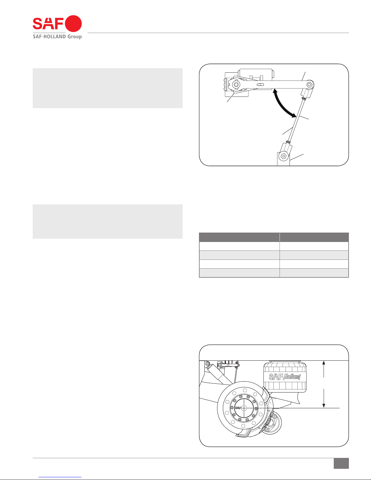
5. Disconnect the linkage from the control arm and lower
the axle mounting bracket (Figure 18).
6. Pin the height control valve so that the valve arm is in
the center or neutral position (Figure 18).
Figure 18
HEIGHT
CONTROL
VALVE
CONTROL ARM
90° OR LESS AT
RIDE HEIGHT
LINKAGE
LOWER AXLE
MOUNTING
BRACKET
12
XL-AS11406OM-en-US Rev E · 2018-04-17 · Amendments and Errors Reserved · © SAF-HOLLAND, Inc., SAF-HOLLAND, HOLLAND, SAF,
and logos are trademarks of SAF-HOLLAND S.A., SAF-HOLLAND GmbH, and SAF-HOLLAND, Inc.

Ride Height Adjustment
7. Measure distance “B” between the valve arm and mounting
bracket holes to determine linkage length (Figure 19).
8. Adjust the linkage to required length and install the hardware
into the upper and lower connections (Figure 19). Torque
hardware to 30-40 in.-lbs. (3-5 N•m).
NOTE: It could be necessary to cut linkage rod to achieve
proper length. Be sure to de-burr rod to prevent
link end damage.
9. Raise the trailer approximately 2" (50 mm) above the
ride height and remove the jack stands.
10. Slowly lower the trailer so that the trailer suspension is
fully collapsed.
11. Pull the pin and apply air to the trailer allowing the
suspension to return to ride height.
12. With the suspension at rest, measure the ride height.
Ride height MUST be within 1/4" (6 mm) of the
suspensions specified ride height.
13. Spray a soapy water mix on all air line connections to
check for air leaks and verify fittings are tight.
IMPORTANT: It is the responsibility of the air system
installer to secure all air lines and check
for air leaks. If air leaks are detected,
repair as required.
Figure 19
HEIGHT
CONTROL
VALVE
CONTROL ARM
LINKAGE
B
LOWER AXLE
MOUNTING
BRACKET
Failure to eliminate air leaks could
compromise the suspension performance
which, if not avoided, could result in
component or property damage.
14. Remove the wheel chocks.
XL-AS11406OM-en-US Rev E · 2018-04-17 · Amendments and Errors Reserved · © SAF-HOLLAND, Inc., SAF-HOLLAND, HOLLAND, SAF,
and logos are trademarks of SAF-HOLLAND S.A., SAF-HOLLAND GmbH, and SAF-HOLLAND, Inc.
13

A
A=B ± 1/8" (3 mm)
C=D ± 1/16" (1 mm)
KINGPIN
B
D
C
Installation Instructions
13. SwingAlign Axle Alignment
13.1 Alignment Preparation
1. Pull the trailer in a straight line for a sufficient distance
to ensure that there are no binds in the suspension.
2. Disengage the trailer parking brakes and make sure the
trailer is empty.
3. Manually measure or use an optical device specifically
designed for alignment measuring to determine the following:
a. Measure the distance from the king pin to the centerline
of the front axle spindles. It is recommended that the
spindle extensions be utilized.
b. Dimensions A and B (Figure 20) MUST be equal to
within 1/8" (3 mm).
c. Measure the distance from the centerline of the front axle
spindles to the centerline of the rear axle spindles.
d. Dimensions C and D (Figure 20) MUST be equal to
within 1/16" (1 mm).
13.2 Alignment Instructions
1. Using the measurements per Section 13.1 Step 3, align
each axle. Align by rotating the alignment bolt head
using a 1-3/8" socket wrench on the front face of the
road-side frame bracket clockwise to move axle forward
(A arrows); counterclockwise to move axle rearward
(B arrows) (Figure 21). Approximately 250 ft.-lbs.
(339 N•m) will be required.
Figure 20
Figure 21
ALIGNMENT
BOLT
WASHER
IMPORTANT: DO NOT loosen the pivot bolts.
IMPORTANT: Two (2) scribe lines on the side of the frame
bracket indicate maximum adjustment for axle
alignment. If the edge of the visible washer
touches either scribe line, the SwingAlign
axle alignment adjustment is “out of stroke.”
Inspect and repair trailer components as
necessary and realign (Figure 22).
IMPORTANT: The SwingAlign design maintains proper
alignment without welding or without
loosening of the pivot connection. DO NOT
weld alignment bolt or pivot bolts
14. Brake Adjustment Instructions
Brakes should be adjusted per axle and brake manufacturer’s
specifications.
For CBX/CB Suspensions with Drum Brake Systems refer to
SAF-HOLLAND Drum Brake Service Manual, XL-TA10006OM.
For CBX Suspension with Disc Brake Systems refer to
SAF-HOLLAND Disc Brake Service Manual, XL-SA10059OM.
14
XL-AS11406OM-en-US Rev E · 2018-04-17 · Amendments and Errors Reserved · © SAF-HOLLAND, Inc., SAF-HOLLAND, HOLLAND, SAF,
(Figure 22).
“A” ARROWS - AXLE FORWARD
“B” ARROWS - AXLE REARWARD
NOTE: 1/2 TURN OF FREE PLAY
IS ACCEPTABLE
Figure 22
ALIGNMENT BOLT ASSEMBLY
ALIGNMENT BOLT
SCRIBE
LINES
WASHER
and logos are trademarks of SAF-HOLLAND S.A., SAF-HOLLAND GmbH, and SAF-HOLLAND, Inc.
PIVOT BOLT
ALIGNMENT PLATES
15. Pre-Operation
Pre-Operation Information
NOTE: In the United States, workshop safety requirements
are defined by federal and/or state Occupational
Safety and Health Act. Equivalent laws may exist
in other countries. This manual is written based
on the assumption that OSHA or other applicable
employee safety regulations are followed by the
location where work is performed.
1. With the vehicle on a level surface, bring air system to
operating pressure (above 85 psig/5.9 bars).
2. Shut off the vehicle and visually check all air control system
fittings for air leaks by applying a soapy water solution and
checking for bubbles at all air connections and fittings.
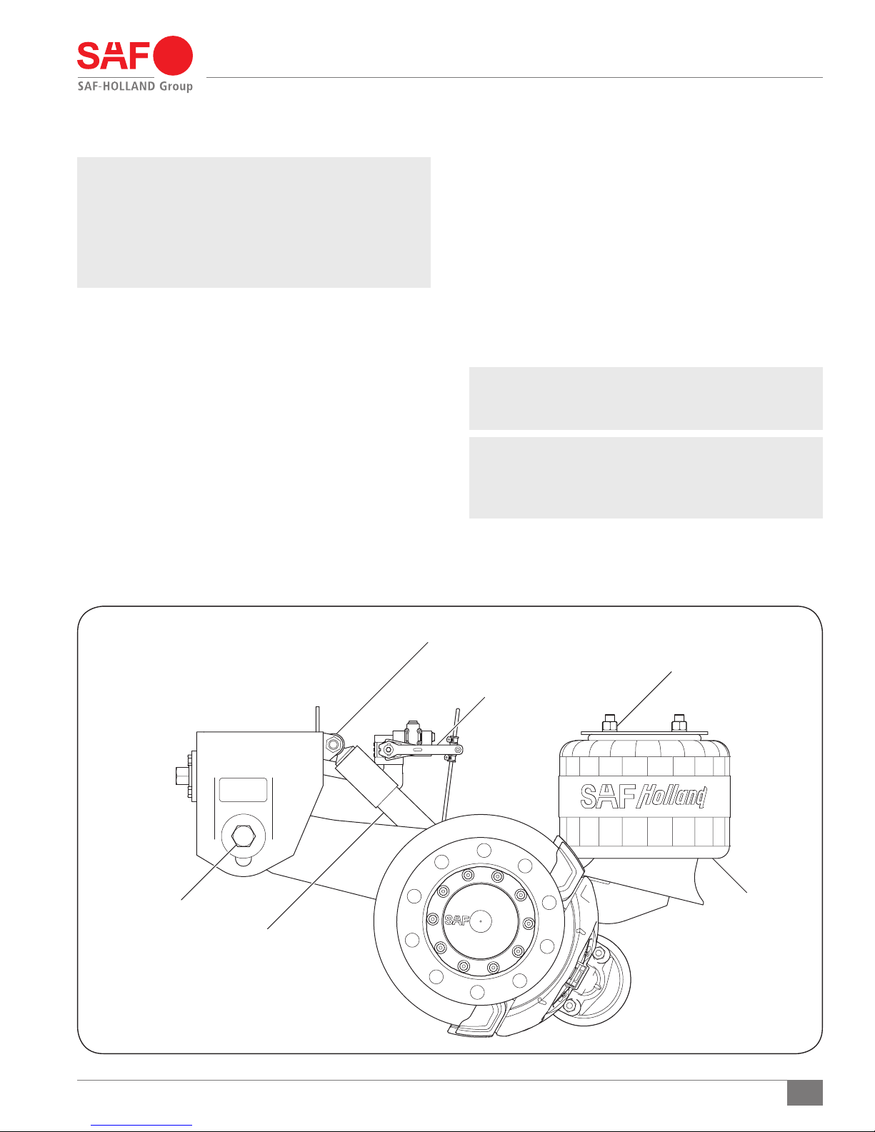
Examine the air springs (Figure 23) for equal firmness.
3. Check the shock absorbers for proper installation and make
sure that the upper and lower 3/4" shock absorber nuts
are torqued to 140-175 ft.-lbs. (190-237 N•m) (Figure 23).
4. Verify that the 1/2" air spring mounting nuts are torqued
to 30-40 ft.-lbs. (41-54 N•m), and the 3/4" air spring
mounting nuts are torqued to 40-45 ft.-lbs. (54-61 N•m)
(Figure 23).
5. With the suspension at full capacity, check that there is a
1" (25 mm) minimum clearance around the air springs.
6. The suspension’s ride height should be within ±1/4" (6 mm)
of the recommended design height. For proper ride height,
refer to Section 12.
7. Determine which pivot bolt style is installed (Figure 23).
If 1-1/8" hex head bolt, verify torque on the nut is
550-600 ft.-lbs. (746-813 N•m).
If 7/8" pan head shear bolt, verify spline has been
sheared off.
IMPORTANT: The SwingAlign design maintains proper
alignment under correct torque without
welding; DO NOT weld.
NOTE: SwingAlign pivot connections are on roadside and
fixed alignment pivot connections are on curbside.
For SwingAlign Connection Axle Alignment
procedure, refer to Section 13.
Figure 23
PIVOT BOLT
UPPER SHOCK ABSORBER NUT
AIR SPRING MOUNTING NUT
HEIGHT CONTROL VALVE
AIR SPRING
SHOCK ABSORBER
XL-AS11406OM-en-US Rev E · 2018-04-17 · Amendments and Errors Reserved · © SAF-HOLLAND, Inc., SAF-HOLLAND, HOLLAND, SAF,
and logos are trademarks of SAF-HOLLAND S.A., SAF-HOLLAND GmbH, and SAF-HOLLAND, Inc.
15

Maintenance and Service Schedule
16. Routine Maintenance and
Daily Inspection
16.3 Visual Inspection Procedure
1. Daily or before each trip, check the suspension to ensure
it is fully operational.
2. Inspect all decals to ensure they are clearly legible and
intact. Clean with a terry cloth towel, soap and water.
3. Visually inspect air springs for sufficient inflation and
that the suspension is at proper ride height. For ride
height details and measurements, refer to Section 12
of this manual.
16.1 Initial Three (3) Months or 5,000 Mile
(8,000 km) Service Inspection
1. Suspension ride height (underside of frame to centerline
of axle) MUST be within ± 1/4" (6 mm) of recommended
design height. For instructions on measuring ride height,
refer to Section 11.
An improperly set ride height could result
in suspension component damage and/or
poor vehicle ride performance.
2. After first three (3) months or 5,000 miles (8,000 km)
of service, whichever comes first, inspect bolts and nuts
at the pivot connections to ensure there are no signs
of movement. Check all other nuts and bolts for proper
torque, refer to the specifications listed in Section 17. Retorque as necessary thereafter.
3. With the vehicle on a level surface and air pressure above
85 psig (5.9 bars), verify that all the air springs are of
sufficient and equal firmness.
IMPORTANT: A schedule for physical and visual inspections
should be established by the operator
based on severity of operation or damage
to the vehicle could occur.
IMPORTANT: During each pretrip and safety inspection
of the vehicle, a visual inspection of the
suspension should be done or damage to
the vehicle could occur.
Visually check for:
Loose, broken or missing fasteners. Repair or replace
as needed.
Loose, damaged, or missing fasteners
can cause loss of vehicle control which,
if not avoided, could result in death or
serious injury.
Air springs – clearances, wear damage, and proper inflation.
Shock absorbers – leaking or damaged.
Cracked parts or welds.
NOTE: Check all air control system fittings for air leaks,
by applying a soapy water solution and checking
for bubbles at all air connections and fittings.
16.2 Routine Physical Inspections
Every 100,000 Miles (160,000 km) or one (1) year, whichever
comes first.
Check all other suspension components for any sign of damage,
looseness, torque loss, wear or cracks. Repair, tighten or
replace damaged part(s) to prevent equipment breakdown.
16
XL-AS11406OM-en-US Rev E · 2018-04-17 · Amendments and Errors Reserved · © SAF-HOLLAND, Inc., SAF-HOLLAND, HOLLAND, SAF,
and logos are trademarks of SAF-HOLLAND S.A., SAF-HOLLAND GmbH, and SAF-HOLLAND, Inc.

17. Torque Specifications
Torque Specifications
Table 3
COMPONENT TORQUE VALUE
Shock Absorber
Pivot Connection, Hex Head Bolt
* Pivot Connection,
Pan Head Shear Bolt
Lower Air Spring Nut
Upper Air Spring Nut
SwingAlign Mounting Fasteners
Only - NOT Pivot Bolt
Height Control Valve Lower Linkage
All torque specifications are ± 5%.
Torques specified are for clean, lubricated threads.
Always Apply torque to nut if possible.
Required re-torquing at every brake re-lining.
* If equipped with 7/8" pan head shear bolt, ensure that the spline is
sheared off and that there are no signs of movement.
140-175 ft.-lbs.
190-237 N•m
550-600 ft.-lbs.
746-813 N•m
Visual Inspection 7/8"
30-40 ft.-lbs.
40-54 N•m
40-45 ft.-lbs.
54-61 N•m
50-60 ft.-lbs.
68-81 N•m
30-40 In.-lbs.
3-5 N•m
FASTENER
SIZE
3/4"
1-1/8"
1/2"
3/4"
1/2"
1/4"
Figure 24
BOLT IDENTIFICATION
GRADE 5 GRADE 8
LOCK NUT IDENTIFICATION
LOCK NUT
GRADE B
7/8" PAN HEAD
SHEAR BOLT
LOCK NUT
GRADE C
6 DOTS3 DOTS
NOTE: Torque specifications listed above are with
clean lubricated / coated threads (Table 3).
All new SAF-HOLLAND fasteners come precoated
from the factory. For bolt and lock nut grade
markings refer to Figure 24.
IMPORTANT: The use of special lubricants with friction
modifiers, such as Anti-Seize or Never-Seez®,
without written approval from SAF-HOLLAND
engineering, will void warranty and could
lead to over torquing of fasteners or other
component issues.
General Information
1. The torque specifications are applied to the nut and NOT
the bolt.
Failure to use the proper fasteners when
servicing the suspension could cause
component failure which, if not avoided,
could result in death or serious injury.
Failure to properly torque all fasteners
could result in component failure which,
if not avoided, could result in death or
serious injury.
XL-AS11406OM-en-US Rev E · 2018-04-17 · Amendments and Errors Reserved · © SAF-HOLLAND, Inc., SAF-HOLLAND, HOLLAND, SAF,
and logos are trademarks of SAF-HOLLAND S.A., SAF-HOLLAND GmbH, and SAF-HOLLAND, Inc.
17

Notes
18
XL-AS11406OM-en-US Rev E · 2018-04-17 · Amendments and Errors Reserved · © SAF-HOLLAND, Inc., SAF-HOLLAND, HOLLAND, SAF,
and logos are trademarks of SAF-HOLLAND S.A., SAF-HOLLAND GmbH, and SAF-HOLLAND, Inc.

Notes
XL-AS11406OM-en-US Rev E · 2018-04-17 · Amendments and Errors Reserved · © SAF-HOLLAND, Inc., SAF-HOLLAND, HOLLAND, SAF,
and logos are trademarks of SAF-HOLLAND S.A., SAF-HOLLAND GmbH, and SAF-HOLLAND, Inc.
19

From fifth wheel rebuild kits to suspension bushing repair kits,
SAF-HOLLAND Original Parts are the same quality components used
in the original component assembly.
SAF-HOLLAND Original Parts are tested and designed to provide
maximum performance and durability. Will-fits, look-alikes or, worse
yet, counterfeit parts will only limit the performance potential and
could possibly void SAF-HOLLAND’s warranty. Always be sure to spec
SAF-HOLLAND Original Parts when servicing your
SAF-HOLLAND product.
SAF-HOLLAND USA
www.safholland.us
SAF-HOLLAND CANADA
WESTERN CANADA
www.safholland.ca
SAF-HOLLAND MEXICO
www.safholland.com.mx
info@safholland.com
SAF-HOLLAND INC.
1950 Industrial Blvd., Muskegon, MI 49442
www.safholland.com
888.396.6501
·
519.537.3494
·
604.574.7491
·
52.55.5362.8743
·
Fax 800.356.3929
·
Fax 800.565.7753
·
Fax 604.574.0244
·
Fax 52.55.5362.8743
·
XL-AS11406OM-en-US Rev E · 2018-04-17 · Amendments and Errors Reserved · © SAF-HOLLAND, Inc., SAF-HOLLAND, HOLLAND, SAF, and logos are trademarks of SAF-HOLLAND S.A., SAF-HOLLAND GmbH, and SAF-HOLLAND, Inc.
 Loading...