

Page 1

Safewatch
BYPASS
RECORD
TEST
FUNCTION
STATUS
VOLUME
PLAY
CODE
CHIME
ESCAPE
ADD
DELETE
SELECT
1 2
4 5
7
9
8
0
ARMED
READY
OFF
AWAY
STAY
3
6
AUX
QuickConnect Plus
Security System
Programming Guide
800-03859-4V2 11/10 Rev. A
Page 2

TABLE OF CONTENTS
Data Fields ................................................................................................................................................................3
✻56 Enhanced Zone Programming ........................................................................................................................11
✻56 Enhanced Zone Programming Worksheet......................................................................................................14
✻80 Device Programming.......................................................................................................................................16
✻81 Zone Lists ........................................................................................................................................................17
Powerline Carrier Device Worksheet for ✻80 and ✻81 ...........................................................................................18
✻83 Enhanced Sequential Mode ...........................................................................................................................19
✻84 Assign Zone Voice Descriptors .......................................................................................................................20
Vocabulary Index (for ✻84 Assign Zone Voice Descriptors)...................................................................................20
✻85 Record Custom Voice Descriptors ..................................................................................................................21
5800 Series Transmitter Loop Numbers Diagram ..................................................................................................22
Safewatch QuickConnect Plus Control Defaults.....................................................................................................23
Safewatch QuickConnect Plus Summary of Connections Diagram .......................................................................24
Refer to the Safewatch QuickConnect Plus Installation and Setup Guide P/N 800-03857-4 or later for
detailed information on programming the system. The Installation and Setup Guide contains full
descriptions for all data fields.
UL
Safewatch QuickConnect Plus is not intended for UL985 Household Fire applications unless a 24hour backup battery (P/N LYNXRCHKIT-HC or LYNXRCHKIT-SHA) is installed.
To Enter Programming Mode:
You may find it convenient to adjust the volume setting before entering the Programming Mode. This will allow
you to clearly hear feedback announcements or system beeps.
1. Power up, then depress [✻] and [#] both at once, within 50 seconds of powering up.
OR
Enter: Installer Code (6 + 3 + 2 + 1) plus 8 + 0 + 0. System will display “Entering Program Mode”.
Notes: 1. If a different Installer Code has been programmed, enter: the New Installer Code + 8 + 0 + 0.
2. If ✻98 was previously used to exit programming, the first method shown above must be used to re-
enter the program mode)
2. Upon entry into Program mode, data field “20 INSTALLER CODE” will be displayed (the first data field in
the system) and both keypad LEDs will flash.
To Program the Data Fields:
1. Press [✻] followed by the desired field number (e.g., ✻21), then make the required entry.
2. The keypad beeps three times after entering data, then displays the next data field in sequence.
3. For phone number and account number fields, press [✻] to end the entry if less than number maximum
number of digits is entered.
4. To view data entered in field, press [#] plus the field that you wish to view (e.g., #21). The system will beep
three times and data programmed for that field will be displayed to the right of the field number. The system
will scroll through the data for longer numbers and a beep will sound after each number is displayed or
three times after the final digit is displayed.
5. To delete an entry, simply press [✻] plus that field number and reenter the correct data. For phone number
and account number fields ✻40-✻44, ✻88 and ✻94, press [✻] + field number + [✻].
Interactive Menu Modes:
There are six interactive menu modes as listed below. To enter these modes, first enter Program mode. While in
Program mode, press [✻] plus the mode number desired (e.g., ✻56).
✻
56 Enhanced Zone Programming .............. For programming zone characteristics, report codes, etc.
✻
80 Device Programming ............................. For programming Powerline Carrier Devices
✻
81 Zone List Programming ......................... For programming zone lists for use with Powerline Carrier Devices
✻
83 Enhanced Sequential Mode .................. For entering transmitter serial numbers
✻
84 Assign Zone Voice Descriptors.............. For assigning voice descriptors to zones
✻
85 Record Custom Voice Descriptors ........ For recording custom voice descriptors
-2-
Page 3

To Initialize Download ID and Subscriber Account Number for Downloading:
✻
96 Resets all subscriber account numbers and CSID in preparation for an initial download.
To Load a Default Set:
✻
97 Enter a number 1-4 corresponding to the selected default table (See the Installation Instructions for the
default tables). Enter 0 if you are not selecting a default table.
To Exit Programming Mode:
✻
98 Exits programming mode and prevents re-entry by: Installer Code + 8+ 0 + 0. If ✻98 is used to exit
programming mode, system must be powered down, then press [✻] and [#] within 50 seconds of power
up to re-enter programming mode.
✻99
Exits programming mode and allows re-entry by: Installer Code + 8 + 0 + 0 or: Power-up, then press [✻]
and [#] within 50 seconds of power up.
Data Field Display Function& Programming Options [ ] = Programmed Table 1 Default Values
SYSTEM SETUP (✻20– ✻30)
20
20
2020
INSTALLER
INSTALLER
INSTALLER INSTALLER
21
21
2121
QUICK
QUICK
QUICK QUICK
22
22
2222
KEYPAD
KEYPAD
KEYPAD KEYPAD
23
23
2323
FORCED
FORCED
FORCED FORCED
24
24
2424
RF
RF
HOUSE
HOUSE
RF RF
HOUSEHOUSE
25
25
2525
X10
X10
HOUSE
HOUSE CODE
X10 X10
HOUSE HOUSE
2 6
26
2626
CHIME
CHIME
CHIME CHIME
27
27
2727
CLO
CLOCK
CK
CLOCLO
CK CK
29
29
2929
DST
DST
MNTH
MNTH
DST DST
MNTH MNTH
30
30
3030
DST WEEK STR/EN D
DST WEEK STR/EN D
DST WEEK STR/EN DDST WEEK STR/EN D
CODE
CODE
CODECODE
ARM
ARM
ENABLE
ENABLE
ARM ARM
ENABLEENABLE
BACKLIGHT
BACKLIGHT
BACKLIGHTBACKLIGHT
BYP ASS
BYPASS
BYPASSBYPASS
ID
ID
CODE
ID ID
CODE
CODECODE
BY
BY
ZONE
ZONE
BY BY
ZONEZONE
DISPLAY
DISPLAY
DISPLAYDISPLAY
STR/END
STR/EN D
STR/EN DSTR/EN D
CODE
CODECODE
Installer Code
Enter 4 digits, 0–9
Quick Arm Enable
0 = no; 1 = yes
Keypad Backlight Timeout
0 = none (backlighting always on); 1 = backlight off after 10secs
Forced Bypass
0 = none; 1 = bypass open zones
RF House ID Code
|
00 = disable all wireless keypad usage; 01–31 = 5804BD/5804BDV house ID
Powerline Carrier Device (X10) House ID
0 = A; 1 = B, 2 = C, 3 = D, 4 = E, 5 = F, 6 = G, 7 = H, 8 = I, 9 = J, #10 = K, #11 = L,
#12 = M, #13 = N, #14 = O, #15 = P
Chime By Zone
0 = no; 1 = yes (program zones to chime on zone list 3)
Real Time Clock Display
0 = no; 1 = yes, display time on keypad
Daylight Saving Time Start/End Month
Start End
1-9, #+10,#+11,#+12. Enter 0,0 if no daylight savings time used.
Daylight Saving Time Start/End Weekend
Start End
0=disable; 1=first; 2=second; 3=third; 4=fourth; 5=last; 6=next to last; 7=third from last
† [1]
[0]
† [1]
[0]
† [0]
† [1]
[00]
DATA FIELDS
†
Entering a number other than the one specified may give unpredictable results.
[6321]
UL installations = 0
[3, 11]
[2,1]
- 3 -
Page 4

Data Field Display Function& Programming Options [ ] = Programmed Table 1 Default Values
ZONE SOUNDS AND TIMING (✻31– ✻39)
31
31
3131
SINGLE
SINGLE
SINGLE SINGLE
32
32
3232
FIRE
FIRE
FIRE FIRE
33
33
3333
ALRM
ALRM
ALRM ALRM
34
34
3434
EXIT
EXIT
EXIT EXIT
35
35
3535
ENTRY
ENTRY
ENTRY ENTRY
36
36
3636
ENTRY
ENTRY
ENTRY ENTRY
38
38
3838
CON
CONFFFF
CONCON
ALARM
ALARM
ALARM ALARM
SND
SND
TIMEOUT
TIMEOUT
SNDSND
TIMEOUT TIMEOUT
SND
SND
SND SND
DELAY
DELAY
DELAYDELAY
DELAY
DELAY
DELAYDELAY
DELAY
DELAY
DELAY DELAY
ARM
ARM ING
ARMARM
SND
SND
SNDSND
TIMEOUT
TIMEOUT
TIMEOUTTIMEOUT
TIME
TIME
TIME TIME
1
1
1 1
2222
ING
DING
DING
INGING
DINGDING
Single Alarm Sounding/Zone
† [0]
0 = Alarm Sounding Per Zone will be the same as the Swinger Shutdown” set in field *92;
1 = yes, limit once per arming period (also applies to long range radio output if “0” is
selected in ✻91 field)
Sounder Timeout
† [0]
0=timeout; 1=no timeout
Alarm Bell Timeout
† [1]
0 = none; 1=4 min; 2=8 min; 3=12 min; 4 = 16 min
Exit Delay
|
45-96 = exit delay time (in seconds)
97 = 120 seconds
Note: The control validates the data entered in this field. If the selection is not valid the control will
SIA: Must be set to a minimum of 45 seconds.
Entry Delay 1 (zone type 01)
|
30-96 = entry delay 1 time (in seconds)
97 = 120 seconds
98 = 180 seconds
99 = 240 second
Note: The control validates the data entered in this field. If the selection is not valid the control will
SIA: The entry delay must be set to a minimum of 30 seconds. The sum of entry delay 1 entered in
Entry Delay 2 (zone type 02)
|
30-96 = entry delay 2 time (in seconds)
97 = 120 seconds
98 = 180 seconds
99 = 240 second
Note: The control validates the data entered in this field. If the selection is not valid the control will
SIA: The entry delay must be set to a minimum of 30 seconds. The sum of entry delay 2 entered in
Confirmation of Arming Ding
Note: Confirmation ding only sounds when Safewatch QuickConnect Plus is Armed Away or disarmed
after being Armed Away. If Safewatch QuickConnect Plus is armed by RF button (key fob), a
confirmation ding occurs immediately after arming regardless of field ✻38 settings. If Safewatch
QuickConnect Plus is disarmed by RF button (key fob), additional disarming confirmation ding occurs
immediately after disarming and is longer than arming confirmation ding.
† [60]
emit a single long beep indicating that the selection has been rejected. The control replaces
the selection with the default value “60”, which is displayed on the keypad, and advances to
the next field.
† [30]
emit a single long beep indicating that the selection has been rejected. The control replaces
the selection with the default value “30”, which is displayed on the keypad, and advances to
the next field.
Field *35 and the burglary abort window entered in *50 should not exceed 1 minute.
† [30]
emit a single long beep indicating that the selection has been rejected. The control replaces
the selection with the default value “30”, which is displayed on the keypad, and advances to
the next field.
Field *36 and the burglary abort window entered in *50 should not exceed 1 minute.
UL installations = 1 (4 min) minimum
UL installations = 60 seconds max.
UL installations = 45 seconds max.
UL installations = 45 seconds max.
UL installations = 0
† [0]
0 =
no arming confirmation ding after arming system by Safewatch QuickConnect Plus keypad or RF
keypad; 1 = arming confirmation ding after arming system by Safewatch QuickConnect Plus keypad
or RF keypad; 2 = arming confirmation ding after arming from RF keypad only
† Entering a number other than the one specified may give unpredictable results.
- 4 -
Page 5

Data Field Display Function& Programming Options [ ] = Programmed Table 1 Default Values
!
39
39
3939
CROSS ZONE TIMER
CROSS ZONE TIMER
CROSS ZONE TIMERCROSS ZONE TIMER
DIALER PROGRAMMING (✻40– ✻53) In fields ✻40, ✻41, ✻42, enter up to the number of digits shown.
Enter 0–9; #+11 for '✻'; #+12 for '#'; #+13 for a pause.
40
40
4040
PABX ACCESS CODE
PABX ACCESS CODE
PABX ACCESS CODEPABX ACCESS CODE
41
41
4141
PRIMARY
PRIMARY
PRIMARY PRIMARY
42
42
4242
SECOND
SECOND
SECOND SECOND
In fields ✻43, ✻44, enter 4 to 10 digits. Enter 0–9; #+11 for B; #+12 for C; #+13 for D; #+14 for E; [#+15 for F].
Enter ✻ as 4th digit, if 3+1 dialer reporting is to be used. If only 3 digits used, pressing ✻ advances to the next
field. Enter [✻] as the fifth digit if a 4-digit account number (for 4+1, 4+2, CID®) is used. To clear entries from
field, press ✻43✻ or ✻44✻.
Examples:
For Acct. 1234, enter: 1 | 2 | 3 | 4 ; For Acct. B234, enter: #+11| 2 | 3 | 4
TEL
TEL
NUM
NUM
TEL TEL
NUMNUM
TEL
TEL
NUM
NUM
TELTEL
NUM NUM
All four digits of the subscriber account number must be entered in Fields
in
✻✻✻✻
48 (option 5), all ten digits of the Subscriber Account number must be entered.
Cross Zone Timer
† [0]
Value Time Window Value Time Window
0 = No Cross Zoning 8 = 2 minutes
1 = 15 seconds 9 = 2 minute, 15 seconds
2 = 30 seconds # + 10 = 2 minute, 30 seconds
3 = 45 seconds # + 11 = 2 minute, 45 seconds
4 = 60 seconds # + 12 = 3 minutes
5 = 1 minute, 15 seconds # + 13 = 3 minute, 15 seconds
6 = 1 minute, 30 seconds # + 14 = 3 minute, 30 seconds
7 = 1 minute, 45 seconds # + 15 = 3 minute, 45 seconds
Note: If option ✻39 is set to “0” Zone List 2 can be used for other purposes.
UL This option is not for use in UL installations.
PABX/Call Waiting Disable
Enter up to 6 digits if PABX is needed to access an outside line. To clear entries from
field, press ✻40✻ OR
Enter“# + 11+ 7+ 0” to program touch-tone sequence “✻70” and cancel call waiting.
Primary Phone Number
Enter up to 20 digits; Do not fill unused spaces. If fewer than 20 digits entered, pressing
✻advances to the next field. To clear entries from field, press ✻41✻.
Secondary Phone Number
Enter up to 24 digits; Do not fill unused spaces. If fewer than 24 digits entered, pressing
✻advances to the next field. To clear entries from field, press ✻42✻.
✻✻✻✻
43 and
✻✻✻✻
44. If ten digit format is selected
For Acct. 1234567890, enter: 1| 2 | 3 | 4 | 5 | 6 | 7 | 8 | 9 | 0 ; For Acct. 123, enter: 1 | 2 | 3 | ✻
43
43
4343
PRIMARY
PRIMARY
PRIMARY PRIMARY
44
44
4444
SECNDRY
SECNDRY
SECNDRYSECNDRY
† Entering a number other than the one specified may give unpredictable results.
ACCOUNT
ACCOUNT#
ACCOUNTACCOUNT
AAAACCOUNT
CCOUNT#
CCOUNTCCOUNT
Primary Subscriber Account Number
See note above.
Secondary Subscriber Account Number
See note above.
- 5 -
Page 6

Data Field Display Function& Programming Options [ ] = Programmed Table 1 Default Values
Dialing
To Follow Me System Phone Number)
must be selected for AAV.
46
46
4646
FOLLOW ME PHONE
FOLLOW ME PHONE#
FOLLOW ME PHONEFOLLOW ME PHONE
47
47
4747
PHONE SYS SELECT
PHONE SYS SELECT
PHONE SYS SELECTPHONE SYS SELECT
48
48
4848
REP FRMT PRI/
REP FRMT PRI/ SEC
REP FRMT PRI/REP FRMT PRI/
49
49
4949
SPLIT/DUAL
SPLIT/DUAL
SPLIT/DUAL SPLIT/DUAL
50
50
5050
ABORT WINDOW
ABORT WINDOW
ABORT WINDOWABORT WINDOW
REP
REP
REPREP
SEC
SECSEC
“Follow Me” Reminder Phone Number
Enter up to 24 digits; Do not fill unused spaces. If fewer than 24 digits entered, pressing ✻
advances to the next field. To clear entries from field, press ✻46✻.
Enter 0-9, #+11 for ‘✻’; #+12 for ‘#’; #+13 for a pause (two seconds).
Phone System Select
† [5]
Central
Station Pulse Tone Pulse Tone
No WATS 0 = No Speaker
WATS 2 = No Speaker
Phone
Phone
Report Format for Primary/Secondary
[7, 7]
Primary Secondary
0 = 3+1, 4+1 ADEMCO L/S STANDARD
1 = 3+1, 4+1 RADIONICS STANDARD
2 = 4+2 ADEMCO L/S STANDARD
3 = 4+2 RADIONICS STANDARD
5 = ADEMCO CONTACT ID® REPORTING
WITH 10-DIGIT SUBS ACCT NO.
Split/Dual Reporting
[0]
To Primary Phone No.
0 = All reports
1 = Alarms, Restore, Cancel
2 = All except Open/Close, Test
3 = Alarms, Restore, Cancel
4 = All except Open/Close, Test
5 = All
To Primary Phone No.
6 = All reports except Open/Close
7 = All reports
8 = All reports
9 = All reports except Open/Close
To Primary Phone No.
10 = All except Open/Close
11 = All reports
12 = All reports
13 = All except Open/Close
‡ Will report users 0, 5-8 or wireless arm/disarm button zones 26-33; all other zones and users do not
report.
Burglary Abort Window
† [2]
1 = 15-second abort window
2 = 30-second abort window
3 = 45-second abort window
SIA The sum of the burglary abort window entered in ✻50 and the entry delays entered in either Field
✻35 or ✻36 should not exceed 1 minute.
Note: The control validates the data entered in this field. If the selection is not valid the control emits a
single long beep indicating that the selection has been rejected. The control replaces the selection
with the default value “2”, which is displayed on the keypad, and advances to the next field.
Note: If you are using Pulse (rotary) Dialing, you must enter the
numbers slowly to allow the pulse dialer time to operate.
5 = With
Speaker Phone
7 = With
Speaker Phone
WITH 4-DIGIT SUBS ACCT NO.
1 = No
Speaker Phone
3 = No
Speaker Phone
- 6 -
Mode
4 = With
Speaker
Phone
6 = With
Speaker Phone
Note: Option 5 or 7 (ADEMCO Contact ID®)
6 or undefined = 4+2 ADEMCO EXPRESS
7 = ADEMCO CONTACT ID® REPORTING
8 = 3+1, 4+1 ADEMCO L/S EXPANDED
9 = 3+1, 4+1 RADIONICS EXPANDED
To Secondary Phone No.
None, unless primary fails, then all
Others
Open/Close, Test
All
All
All
To Paging Number
Alarms, Open/Close‡, Troubles
Alarms, Troubles
Alarms, Open/Close‡, Troubles
Alarms, Troubles
Alarms, Open/Close‡, Troubles
Alarms, Troubles
Alarms, Open/Close‡, Troubles
Open/Close‡
Page 7
Data Field Display Function& Programming Options [ ] = Programmed Table 1 Default Values
51
51
5151
PERIOD
PERIOD
PERIOD PERIOD
TEST
TEST
TEST TEST
SESCOA/RADIONICS
SESCOA/RADIONICS
SESCOA/RADIONICSSESCOA/RADIONICS
LACK
LACK
LACK LACK
REPORT
REPORT
REPORT REPORT
FALSE AL
FALSE ALAAAARM OPTS
FALSE ALFALSE AL
RF
RF
RF RF
† Entering a number other than the one specified may give unpredictable results.
TO PROGRAM SYSTEM STATUS, & RESTORE REPORT CODES (✻59–✻76, & ✻89):
With a 3+1 or 4+1 Standard Format: Enter a code in the first box: 1–9, 0, B, C, D, E, or F. Enter "#+10" for 0, "#+11" for B, "#+12" for C,
"#+13" for D, "#+14" for E, "#+15" for F.
A "0" (not "#+10") in the first box will disable a report.
A "0" (not "#+10") in the second box will result in automatic advance to the next field when programming.
With an Expanded or 4+2 Format: Enter codes in both boxes (1st and 2nd digits) for 1–9, 0, or B–F, as described above.
A "0" (not "#+10") in the second box will eliminate the expanded message for that report.
A "0" (not "#+10") in both boxes will disable the report.
With ADEMCO Contact ID Reporting: Enter any digit (other than "0") in the first box, to enable zone to report (entries in the second boxes
will be ignored). A "0" (not "#+10") in the first box will disable the report.
Examples: For Code 3 (single digit), enter: 3 | 0
52
52
5252
53
53
5353
54
54
5454
55
55
5555
57
57
5757
58
58
5858
JAM
JAM
JAM JAM
TTTTEST
EST
ESTEST
REP
REP
OFFSET
OFFSET
REP REP
OFFSETOFFSET
OF
OF
USAGE
USAGE
OF OF
USAGEUSAGE
CHANNELS
CHANNELS
CHANNELSCHANNELS
RM OPTS
RM OPTSRM OPTS
DETECTION
DETECTION
DETECTIONDETECTION
REP
REP
REP REP
Periodic Test Report
† [0]
0 = none; 1 = 24 hours; 2 = weekly; 3 = 30 days
First Test Report Offset
† [2]
0 = 24 hour; 1 = 6 hours; 2 = 12 hours; 3 = 18 hours
SESCOA/Radionics Select
[0]
0 = Radionics (0–9, B–F reporting);
1 = SESCOA (0–9 only reporting). Select 0 for all other formats.
Lack of Usage Notification
[0]
0 = Disabled
1 = 1 day
Reporting Channels
[0]
0 = Telco Line (no Radio)
1 = LRR/IP(Digital Communication only) and Telco Line
3 = LRR/IP (Digital Communication only) (no Telco Line)
5 = LRR/IP (Digital Communication with AAV) (Telco Line connections for 2-way voice
session only, if applicable)
False Alarm Options
[7]
Value Cancel Alarm Display Auto Stay Arming Exit Time Restart/Reset
0 = Disabled Disabled Disabled
1 = Disabled Disabled Enabled
2 = Disabled Enabled Disabled
3 = Disabled Enabled Enabled
4 = Enabled Disabled Disabled
5 = Enabled Disabled Enabled
6 = Enabled Enabled Disabled
7 = Enabled Enabled Enabled
Note: The control validates the data entered in this field. If the selection is not valid it will emit a single
long beep indicating that the selection has been rejected. The control replaces the selection
with the default value “7”, which is displayed on the keypad, and advances to the next field.
RF Jam Detection
[0]
0 = no RF Jam Detection; 1 = RF Jam Detect on, no CS report;
2 = RF Jam Detect on with CS report (if trouble/restore report is enabled in fields ✻60, ✻71)
(enter Test Code in field ✻64)
2 = 7 days
3 = 27 days
Note: For event logging option 2 must be selected.
4 = 90 days
5 = 180 days
6 = 365 days
For Code 3 2 (two digits), enter: 3 | 2
For Code B 2 (Hexadecimal), enter: #+11 | 2
- 7 -
Page 8
Data Field Display Function& Programming Options [ ] = Programmed Table 1 Default Values
expanded or 4+2 reporting is selected.
SYSTEM STATUS REPORT CODES (✻59–✻68)
59
59
5959
EXIT
EXIT
ERROR
ERROR
EXITEXIT
ERROR ERROR
60
60
6060
TROUBLE
TROUBLE
TROUBLE TROUBLE
61
61
6161
BYPASS
BYPASS
BYPASS BYPASS
62
62
6262
AC
AC
LOSS
LOSS
ACAC
LOSS LOSS
66663333
LOW
LOW
BAT
BAT
LOW LOW
BAT BAT
66664444
TEST
TEST
REP
REPORT
TESTTEST
RESTORE REPORT CODES (✻70–✻76)
REPREP
65
65
6565
OPEN
OPEN
REPORT
OPEN OPEN
AWAY/STAY
AWAY/STAY
AWAY/STAY AWAY/STAY
RF
RF
RF RF
CANCEL
CANCEL
CANCEL CANCEL
RECENT CLOSE REP
RECENT CLOSE REP
RECENT CLOSE REPRECENT CLOSE REP
ALARM
ALARM
ALARM ALARM
TROUBLE RES REP
TROUBLE RES REP
TROUBLE RES REPTROUBLE RES REP
BYPASS RES REP
BYPASS RES REP
BYPASS RES REPBYPASS RES REP
AC R
AC R ESTORE REP
AC RAC R
REPORT
REPORT REPORT
66
66
6666
67
67
6767
TRANS
TRANS
TRANSTRANS
68
68
6868
69
69
6969
70
70
7070
71
71
7171
72
72
7272
73
73
7373
ESTORE REP
ESTORE REPESTORE REP
REP
REP
REP
REP REP
REP
REP
REP REP
REP
REP
REP REP
ORT
ORTORT
REP
REP
REP REP
RES
RES
RESRES
REP
REP
REPREP
REP
CODE
CODE
REP REP
CODECODE
CODE
CODE
CODECODE
CODE
CODE
CODE CODE
CODE
CODE
CODECODE
CODE
CODE
CODE CODE
CODE
CODE
CODECODE
REP
REPORT
REPREP
LB
LB
REP
REP
LB LB
REPREP
CODE
CODE
CODECODE
REPORT
REPORT
REPORT REPORT
ORT
ORTORT
Exit Error Report Code
[1]
Trouble Report Code
| [1,0]
Bypass Report Code
| [0,0]
AC Loss Report Code
| [0,0]
Low Bat Report Code
| [1,0]
Test Report Code
| [1,0]
Open Report Code
†† [0]
Arm Away/Stay Report Code
†† [0,0]
AWAY STAY
RF Transmitter Low Battery Report Code
| [1,0]
Cancel Report Code
| [1,0]
Recent Close Report Code
| [1]
Note: The control validates the data entered in this field. If the selection is not valid the control will
emit a single long beep indicating that the selection has been rejected. The control replaces
the selection with the default value “1”, which is displayed on the keypad, and advances to the
next field.
Alarm Restore Report Code
[1]
Trouble Restore Report Code
| [1,0]
Bypass Restore Report Code
| [0,0]
AC Restore Report Code
| [0,0]
2nd digit is automatically sent as 2nd digit of the zone alarm report
code programmed in ✻56, if expanded or 4+2 reporting is selected.
(†† 2nd digit is automatically sent as the user
number if expanded or 4+2 reporting is selected.)
2nd digit is automatically sent as 2nd digit of the
zone alarm report code programmed in ✻56, if
- 8 -
Page 9
Data Field Display Function& Programming Options [ ] = Programmed Table 1 Default Values
74
74
7474
LO
LO
BAT
BAT
RES
RES
REP
LO LO
BATBAT
75
75
7575
RF
RF
LOBAT
LOBAT
RFRF
LOBAT LOBAT
76
76
7676
TEST
TEST
RES
RES
TEST TEST
DYNAMIC SIGNALING FIELD (✻77)
OUTPUT AND SYSTEM SETUP (✻80, ✻81, ✻83–✻85) See Procedures later in this manual.
RES RES
77
77
7777
DYNAMIC SIG OPTS
DYNAMIC SIG OPTS
DYNAMIC SIG OPTSDYNAMIC SIG OPTS
77778888
PROG TONE GEN TM
PROG TONE GEN TM
PROG TONE GEN TMPROG TONE GEN TM
86
86
8686
MULTI
MULTI ----MODE
MULTIMULTI
AUX
AUX
AUX AUX
PAGER CHARACTERS
PAGER CHARACTERS
PAGER CHARACTERSPAGER CHARACTERS
EVNT
EVNT
EVNT EVNT
87
87
8787
88
88
8888
89
89
8989
MODE
MODE MODE
FUN C
FUNC
FUNCFUNC
LOG
LOG
LOG LOG
RES RES
RRRRES
REPORT
REPORT
REPORTREPORT
1BTN
1BTN
1BTN 1BTN
80%
80%
80% 80%
REP
REP REP
ES
REP
REP
ESES
REP REP
EMAIL
EMAIL
EMAILEMAIL
PG
PG
PG PG
REP
REP
REPREP
Low Bat Restore Report Code
| [1,0]
RF Transmitter Low Battery Restore Report Code
| [1,0]
Test Restore Report Code
| [1,0]
Dynamic Signaling Options
| [0, 0]
1st Entry (delay before switch CS reporting path)
0 = Redundant
reporting on dialer
and LRR/IP device
1 = 15 seconds
2 = 30 seconds
2nd Entry
0 = Primary Dialer
Preferred Channel
Programmable Tone Generation Time
| [0, 0]
00 = Disabled
01-09 = 100-900 ms
10-99 = 1.0 – 9.9 secs
Multi-Mode (E-Mail Notification) (RIS is always enabled)
[0]
0 = Disable multi-mode devices (RIS enabled)
1 = Enable multi-mode device address #6 only (RIS enabled)
2 = Enable multi-mode device address #7 only (RIS enabled)
3 = Enable multi-mode addresses (RIS enabled)
Aux Function/ 1-Button Paging
[0]
0 = Aux key performs defined function (macro);
1 = Aux key sends message to pager or voice message to follow me system phone no.
If 1, you must also select an option 6-9 in field ✻49 for the pager or 10-13 for the follow me
system announcement.
Pager Characters
Up to 16 digits can be entered that will appear in front of the 7-digit pager message sent by
the control. Refer to the Installation Instructions (fields ✻87, ✻88 and ✻49) for full
descriptions of the paging feature. You do not need to fill all 16 digits (press [✻] to
advance to next field).
To clear entries, enter ✻88✻. To enter “✻” = [#] + [11]; To enter “#” = [#] + 12]; To
enter 2-second pause = [#] + [13] (some pagers require an additional delay [pause] in
order to receive the entire message)
Event Log 80% Full Report Code
| [0,0]
3 = 45 seconds
4 = 60 seconds
5 = 75 seconds
6 = 90 seconds
7 = 105 seconds
1 = LRR/IP
Preferred Channel
8 = 120 seconds
9 = 135 seconds
#10 = 150 seconds
#11 = 165 seconds
#12 = 180 seconds
2 = LRR/IP
reporting only
#13 = 195 seconds
#14 = 210 seconds
#15 = 225 seconds
- 9 -
Page 10

Data Field Display Function& Programming Options [ ] = Programmed Table 1 Default Values
90
90
9090
EVNT LOG O PTIONS
EVNT LOG O PTIONS
EVNT LOG O PTIONSEVNT LOG OPTIONS
91
91
9191
AAV/REM
AAV/REM
AAV/REMAAV/REM
92
92
9292
SWINGER SHU TDOWN
SWINGER SHU TDOWN
SWINGER SHU TDOWNSWINGER SHUTDOWN
DOWNLOAD INFORMATION (✻93–✻95)
93
93
9393
FLEXBLE
FLEXBLE
FLEXBLE FLEXBLE
94
94
9494
DOWNLOAD
DOWNLOAD
DOWNLOAD DOWNLOAD
PHN
PHN
CTRL
CALLBACK
CALLBACK
CALLBACKCALLBACK
CTRL
PHN PHN
CTRLCTRL
PHONE
PHONE #
PHONEPHONE
Event Logging
any non-zero selection is made.
[3]
0 = None; 1 = Alarm/Alarm Restore; 2 = Trouble/Trouble Restore; 4 = Bypass/Bypass
Restore; 8 = Open/Close.
Example: To select “Alarm/Alarm Restore”, and “Open/Close”, enter 9 (1 + 8); To select
all, enter #15.
Alarm Audio Verification (AAV)/Remote Phone Control
[2]
0 = None
1 = AAV and remote phone control
2 = remote phone control only
4 = AAV only
Notes: (1) In order to activate the Remote Phone Control feature and defeat an answering machine,
(2) Remote phone session will be terminated if a report must be sent.
(3) Alarm Audio Verification will only function when Contact ID® is selected. AAV cannot be
(4) If an alarm will be reported to primary and secondary phone numbers, AAV can only
(5) If an alarm will be reported to a follow me phone number (10-12 in field ✻49) AAV cannot
(6) If AAV is selected and LRR/IP communications device is enabled, you must enter "0"
Swinger Shutdown
[1]
1 = shutdown after one alarm; 2 = shutdown after two alarms
Note: The control validates the data entered in this field. If the selection is not valid the control will
Flexible Callback
[0]
0 = No flexible callback; 1 = Last digit flexible;
2 = Last 2 digits flexible; 3 = Last 3 digits flexible
Download Phone Number
Note: In UL installations, downloading may only be performed if a technician is at the site.
ensure that the correct ring detection count (“15”) has been programmed in field ✻95.
used for UL installations.
function via the secondary number.
be used.
(primary dialer preferred channel) as the second entry in Field ✻77.
emit a single long beep indicating that the selection has been rejected. The control replaces
the selection with the default value “1”, which is displayed on the keypad, and advances to
the next field.
Note: System messages are logged when
Enter up to 20 digits, 0–9; #+11 for '✻'; #+12 for '#'; #+13 for a pause. Do not fill unused
spaces. If fewer than 20 digits entered, pressing ✻ advances to the next field. To clear
95
95
9595
RING
RING
DET
DET
COUNT
DET DET
COUNT
COUNTCOUNT
RING RING
entries from field, press ✻94✻.
Ring Detection Count for Downloading/Remote Phone Control Mode
[15]
0 = Disable Station Initiated Download
1–14 = number of rings
(1–9, [#]+10 =10, [#] +11 =11, [#] +12 =12, [#] +13 =13, [#] +14 =14);
15 = answering machine defeat ([#] +15 =15)
- 10 -
Page 11

✻✻✻✻56 ENHANCED ZONE PROGRAMMING PROCEDURE
This interactive menu mode is used to program zone numbers, zone types, alarm and report codes, and to
identify the type of loop input device and can be used for entering 5800 Series transmitter serial numbers. Press
✻56 while in programming mode.
Note: Entering a number other than the one specified may give unpredictable results.
A01
A01
A01A01
ZONE
ZONE
NUMBER
ZONE ZONE
NUMBER
NUMBERNUMBER
b
ZONE
ZONE
TYPE
ZONE ZONE
REPORT
REPORT
REPORTREPORT
INPUT
INPUT
INPUTINPUT
LOOP
LOOP#/AUTO
LOOPLOOP
LOOP
LOOP#/AUTO LEARN
LOOPLOOP
TYPE
TYPETYPE
CCCC
CODE
CODE
CODE CODE
d
TYP E
TYPE
TYPE TYPE
EEEE
AUTO
AUTO AUTO
EEEE2L LEARNED
2L LEARNED
2L LEARNED2L LEARNED
AUTO LEARN
AUTO LEARNAUTO LEARN
LEARN
LEARN
LEARNLEARN
Zone Number
Enter the 2-digit zone number to be programmed. The system will announce the Voice
Descriptor for the selected zone, if it is programmed.
00 = exit zone programming mode
01 = Hardwire Zone
2-25 = RF transmitter zones (only)
26-41 = RF button zones (only)
92 = Duress
95, 96, 99 = Panic zones
[✻] = Continue
Zone Type
Enter the 2-digit zone type (zt) for this zone. if 00 is entered, the system will skip to DELETE
ZONE PARAMETERS prompt (F)
00 = Not Used
01 = Entry/Exit #1
02 = Entry/Exit #2
03 = Perimeter
04 = Interior Follower
05 = Trouble Day/Alarm Night
06 = 24 Hr Silent
07 = 24 Hr Audible
08 = 24 Hr Aux
09 = Fire without Verification
10 = Interior with Delay
14 = Carbon Monoxide
20 = Arm–Stay
21 = Arm–Away
22 = Disarm
23 = No Alarm Response
24 = Silent Burglary
[✻] = Continue
[#] = Return to previous prompt
Report Code
Enter the Report Code (rc) for this zone. Report consists of 2 hexadecimal digits, each
composed of 2 numerical digits. (A = 10, B = 11, C = 12, D = 13, E = 14, F = 15) (see
Report Code description for explanation of codes).
[✻] = Continue; If this is zone 95, 96 or 99, the system skips to the VOICE DESCRIPTOR
prompt (1C)
[#] = Return to previous prompt
Input Type
Enter the input type (i) for the transmitter assigned to this zone.
Note: Zones 2-25 should be assigned as Input Type 3 or 4 and Zones 26-41 should be
assigned as Type 5 only.
3 = Supervised RF (RF)
4 = Unsupervised RF (UR)
5 = Button type (BR)
[✻] = Continue
[#] = Return to previous prompt
Enroll Loop Number or Loop & Serial Number via RF Learning
For BR type devices (device type 5), two (2) transmissions (two key depressions at least
five seconds apart) are required. For RF and UR device types (device type 3 and 4), four
(4) transmissions are required (fault, restore and fault, restore). The device should be at
least 5 feet away from the control when enrolling via RF learning.
Note: There is a 52-second time-out for RF enrolling. At the end of the time-out, the system
returns to the INPUT TYPE prompt (d). If enrolled, loop number and “LEARNED” will
be displayed.
Depress the key of the BR type device two times (two transmissions) or fault and restore
the RF or UR type device two times (four transmissions).
Two beeps will sound after the second transmission of the BR type device or the fourth
transmission of the RF or UR type device confirming that the loop number and serial
number have been learned. The loop number that has been learned will be displayed
(loop 2 shown) and the system will announce the Voice Descriptor for the zone.
Press [✻] to continue.
- 11 -
Page 12

✻✻✻✻56 ENHANCED ZONE PROGRAMMING PROCEDURE
1111AL
AL
A094
A094----4129
AL AL
A094A094
ENROLL MODE
ENROLL MODE
ENROLL MODEENROLL MODE
1111ALC
ALC A094
ALC ALC
ENROLL MODE
ENROLL MODE
ENROLL MODEENROLL MODE
EEEE
LOOP
LOOP#/AUTO LEARN
LOOPLOOP
FFFF
DELETE
DELETE
DELETE DELETE
1111AAAA
ENROLL
ENROLL
ENROLLENROLL
1111b
SERIAL
SERIAL
SERIALSERIAL
1AL
1AL A094
A094----4129
1AL 1AL
A094A094
ENROLL MODE
ENROLL MODE
ENROLL MODEENROLL MODE
1ALC
1ALC
A094
1ALC1ALC
ENROLL MODE
ENROLL MODE
ENROLL MODEENROLL MODE
4129
41294129
A094----4129
A094A094
A094----4129
A094A094
4129
41294129
AUTO LEARN
AUTO LEARNAUTO LEARN
ZONE
ZONE
ZONEZONE
MODE
MODE
MODE MODE
NUMBER
NUMBER
NUMBERNUMBER
4129
41294129
4129
41294129
Enroll Loop Number or Loop & Serial Number via RF Learning (Continued)
The serial number of the device that has been learned will be displayed. “1AL” will be
displayed in front of the serial number.
Fault and restore the sensor again to confirm the serial number.
The system will announce the Voice Descriptor for the zone and “1ALC” will be displayed
in front of the serial number.
Press [✻] to continue. System will advance to Prompt “1C”
Enter Loop Number or Loop & Serial Number via Manual Entry
Enter the desired loop number and press [✻] to continue (see the transmitter’s Installation
Instructions for specific loop designations). If “LEARNED” is displayed, the zone’s serial
number has already been enrolled.
Note: The loop number can be changed even if the zone has already been entered. Care
should be taken when using this feature. It is possible to make zones inoperable by
creating a mismatch of a working serial number/loop number combination. This
should be re-confirmed if the loop number is changed.
1-4 = Loop number for the zone of the transmitter being entered or learned
0 = Delete Serial Number prompt (F)
[✻] = Continue to the ENROLL MODE prompt (1A)
[#] = Return to previous prompt
Delete Zone Parameters
If 00 was entered in the Zone Type field or if 0 was entered in the Loop Number field,
confirmation of the delete request will delete all information associated with zone currently
being programmed.
Note: 00 was entered as a zone type in prompt (b), 00 will be retained and system will
advance to prompt (1C).
0 = Discard the delete request.
1 = Confirm the requested delete.
Enroll Mode (this prompt applies to Manually enrollment only)
Confirm, delete or enter Serial Number
0 = Skip to the VOICE DESCRIPTOR prompt (1C). If zone type is “00”, then skips to
DELETE SERIAL NUMBER prompt instead.
1 = Enroll now and proceed to SERIAL NUMBER prompt (1b) (If “LEARNED” is not
displayed).
2 = Copy the last serial number from the local memory buffer (If “LEARNED” is not
displayed).
9 = Delete existing serial number. (Only if “LEARNED” is displayed).
[✻] = Advance to the VOICE DESCRIPTOR prompt (1C). This will save all zone
parameters.
[#] = Return to the loop number prompt (E).
Serial Number (this prompt applies to Manually enrollment only)
Manually enter the 7-digit serial number printed on the transmitter. If an incorrect digit is
entered, press the [#] key to return to prompt (1A). When all 7 digits are entered, press
the [✻] key. The serial number will be copied into EEROM and the local memory buffer and
the system will return to the (1A) prompt and “LEARNED” will be displayed. If 52 seconds
pass and no entry is been made, the system will return to prompt (1A).
The serial number of the device that has been learned will be displayed. “L” will be
displayed in front of the serial number.
Fault and restore the sensor again to confirm the serial number.
The system will announce the Voice Descriptor for the zone and “LC” will be displayed in
front of the serial number.
Press [✻] to continue. System will advance to Prompt “1C”
Note: In order for all parameters to be accepted, you must advance to prompt (1C).
- 12 -
Page 13

✻✻✻✻56 ENHANCED ZONE PROGRAMMING PROCEDURE
1111CCCC
ZONE DESCRIPTOR
ZONE DESCRIPTOR
ZONE DESCRIPTORZONE DESCRIPTOR
1111d
Note: System displays 2-digit
selection & alpha
descriptor OR 99 “No
selection”
1111EEEE
Note: System displays 2digit selection & alpha
descriptor OR 99 “No
selection”
Note: System displays 2digit selection & alpha
descriptor OR 99 “No
selection”
† See ✻84 ASSIGN ZONE VOICE DESCRIPTORS section for Vocabulary Index.
1111FFFF
Voice Descriptor
0 = Skip to next zone (A)
1 = Enter descriptor mode (existing zone descriptor will be announced, then descriptor 1
will be repeated)
Descriptor 1
Enter [#] + 2-digit vocabulary index† number of first descriptor word for this zone.
To change the entered index number, press [#] + desired index number.
6 = accept word and advance to descriptor 2 (descriptor 2 will be announced)
8 = accept word and advance to next zone (prompt A) – zone descriptor will be
announced
Press any other key to repeat the selected word
Descriptor 2
Enter [#] + 2-digit vocabulary index† number of second descriptor word for this zone.
To change the entered index number, press [#] + desired index number.
6 = accept word and advance to descriptor 3 (descriptor 3 will be announced)
8 = accept word and advance to next zone (prompt A) – zone descriptor will be
announced
Press any other key to repeat the selected word
Descriptor 3
Enter [#] + 2-digit vocabulary index† number of third descriptor word for this zone.
To change the entered index number, press [#] + desired index number.
6 or 8 = accept word and advance to next zone (prompt A) – zone descriptor will be
announced
Press any other key to repeat the selected word
- 13 -
Page 14

✻✻✻✻56 ENHANCED ZONE PROGRAMMING WORKSHEET
Fill in the required data on this worksheet, then follow the programming procedure.
ZONES ON CONTROL: See explanation of headings (defaults shown are for Table 1)
Zone Zone No. Zone Alarm rpt code Vocabulary
Description (A 01) Type (zt) (hex) (rc) Index
Wired Zone 1 0 1
Duress 9 2
Keypad Panic (1 & ✻) 9 5
Keypad Panic (3 & #) 9 6
Keypad Panic (✻ & #) 9 9
Zone No. Zone Alarm Report Input Loop Transmitter Vocabulary
(A 01) Type (zt) Code in hex (rc) Type (i) No. (l) Serial Number Index
0|2 | [01] | | [01 00] [3] [2] | | [47-04-99]
0|3 | [01] | | [01 00] [3] [2] | | [33-04-99]
0|4 | [03] | | [01 00] [3] [2] | | [80-99-99]
[00] [00 00] I I
— — [00 00] I I
[09] [01 00] I I
[00] [00 00] I I
[07] [01 00] I I
0|5 | [10] | | [01 00] [3] [1] | | [56-99-99]
0|6 | | | | |
0|7 | | | | |
0|8 | | | | |
0|9 | | | | |
1|0 | | | | |
1|1 | | | | |
1|2 | | | | |
1|3 | | | | |
1|4 | | | | |
1|5 | | | | |
1|6 | | | | |
1|7 | | | | |
1|8 | | | | |
1|9 | | | | |
2|0 | | | | |
2|1 | | | | |
2|2 | | | | |
2|3 | | | | |
2|4 | | | | |
2|5 | | | | |
- 14 -
Page 15

✻✻✻✻56 ENHANCED ZONE PROGRAMMING WORKSHEET
Button Zones
Zone No. Zone Alarm Report Input Loop Transmitter Vocabulary
(A 01) Type (zt) Code in hex (rc) Type (i) No. (l) Serial Number Index
2|6 | [21] | | [01 00] [5] [3 | |
2|7 | [22] | | [01 00] [5] [2] | |
2|8 | [20] | | [01 00] [5] [4] | |
2|9 | [23] | | [00 00] [5] [1] | |
3|0 | [21] | | [01 00] [5] [3] | |
3|1 | [22] | | [01 00] [5] [2] | |
3|2 | [20] | | [01 00] [5] [4] | |
3|3 | [23] | | [00 00] [5] [1] | |
3|4
| | | | |
3|5 | | | | |
3|6 | | | | |
3|7
| | | | |
3|8 | | | | |
3|9
| | | | |
4|0 | | | | |
4|1 | | | | |
EXPLANATION OF ZONE ASSIGNMENT TABLE HEADINGS
A 01 = ZONE No. Zone Numbers are 01 (wired), 02-25 (RF) only, 26-41 (Button) only, 92 (duress), 95, 96, 99 (panic)
zt = ZONE TYPE
rc = ALARM REPORT CODE Two Hex Digits. For each Hex Digit, enter: 00–09 for 0–9, 10 for A, 11 for B,12 for C, 13
i = INPUT TYPE Enter 3 for RF: Supervised RF
l = LOOP NUMBER Used with 5800 RF Loop Input Devices. Record transmitter loop number. Entries are 1-4,
00 = Not Used
01 = Entry/Exit #1
02 = Entry/Exit #2
03 = Perimeter
04 = Interior Follower
05 = Trouble Day/Alarm Night
06 = 24 Hr Silent
07 = 24 Hr Audible
08 = 24 Hr Aux
for D, 14 for E, 15 for F. If "00" is entered as the first digit, there will be no report for that
zone.
For Contact ID reporting, this is enabling code only. Enter any hex digit (other than 00) in
the first pair of boxes. The second pair of boxes is ignored.
Enter 4 for UR: Unsupervised RF
Enter 5 for BR: Button Type RF
depending on device being used. Refer to the transmitter’s instructions for appropriate
loop numbers.
09 = Fire without Verification
10 = Interior with Delay
14 = Carbon Monoxide
16 = Fire with verification
20 = Arm–Stay
21 = Arm–Away
22 = Disarm
23 = No Alarm Response
24 = Silent Burglary
Zones 2-25 should be assigned as Input Type 3 or 4
and Zones 26-41 should be assigned as Type 5 only.
- 15 -
Page 16

✻✻✻✻80 DEVICE PROGRAMMING
Use this mode to program Powerline Carrier Devices or zone lists for Chime by Zone feature. It is also used to
program the Remote Services Multi-mode (e-mail) event triggers. Press ✻80 while in programming mode.
Note: Entering a number other than the one specified may give unpredictable results.
80
80
8080
DEVICE
DEVICE
DEVICE DEVICE
A01
A01
A01A01
DEVICE
DEVICE
DEVICE DEVICE
b
DEVICE
DEVICE
DEVICE DEVICE
CCCC
START
START
STARTSTART
d
START
START
STARTSTART
EEEE
START
START
STARTSTART
FFFF
STOP
STOP
STOPSTOP
1A
1A
1A1A
STOP
STOP
STOP STOP
PROG
PROG
PROGPROG
NUMBER
NUMBER
NUMBERNUMBER
ACTION
ACTION
ACTIONACTION
EVENT
EVENT
EVENT EVENT
ZONE
ZONE
ZONE ZONE
ZONE
ZONE
ZONE ZONE
ZONE
ZONE
ZONE ZONE
ZONE
ZONE
ZONEZONE
MENU
MENU
MENU MENU
TYPE
TYPE
TYPETYPE
LIST
LIST
LIST LIST
TYPE
TYPE
TYPETYPE
LIST
LIST
LISTLIST
TYP E
TYPE
TYPE TYPE
Powerline Carrier Device Programming
0 = Exit mode, upon which this prompt blinks.
1 = Enter mode
Device Number
Enter the 2-digit device number to be programmed
01-08 = X10 device number
09-16 = Multimode (e-mail) event triggers
[✻] = Continue
00 = Exit Device Programming mode (displays blinking 80; enter ✻ + desired data field or
menu mode number)
Device Action
Enter the 1-digit action, 0-3, for the device being programmed (current action is displayed).
0 = No response 3 = Pulse on and off
1 = Close for 2 seconds [✻] = Continue
2 = Close and stay closed [#] = Return to previous prompt
Start Event Type (If applicable)
Enter the 1-digit start event type, 0-3, for the device being programmed.
0 = Not used 3 = Trouble
1 = Alarm [✻] = Continue
2 = Fault [#] = Return to previous prompt
Start Zone List (If applicable)
Enter the 1-digit zone list number, 1-3, or 0 if not used, for the device being programmed.
[✻] = Continue
[#] = Return to previous prompt
Start Zone Type (If applicable)
Enter the 2-digit start zone type for the device being programmed (see Powerline Carrier
Device Worksheet for zone type/system operation codes later in this manual).
[✻] = Continue
[#] = Return to previous prompt
Stop Zone List (If applicable)
Enter the 1-digit zone list number, 1-3, or 0 if not used, for the device being programmed.
[✻] = Continue
[#] = Return to previous prompt
Stop Zone Type (If applicable)
Enter the 2-digit stop zone type for the device being programmed (see Powerline Carrier
Device Worksheet for zone type/system operation codes later in this manual).
[✻] = Continue to Device Number prompt (A)
[#] = Return to previous prompt
- 16 -
Page 17

Use this mode to define zone lists for Powerline Carrier Devices and/or for the chime by zone feature. Press ✻81
while in programming mode.
Note: Entering a number other than the one specified may give unpredictable results.
81
81
8181
ZONE
ZONE
ZONEZONE
A 01
A01
A01A01
ZONE
ZONE
ZONEZONE
b
ZN
ZN
ENTRY
ENTRY
ZN ZN
ENTRY ENTRY
CCCC
DEL
DEL
WHOLE
WHOLE
DEL DEL
WHOLEWHOLE
d
DEL
DEL
1111
DEL DEL
EEEE
DELETE
DELETE
DELETE DELETE
LISTS
LISTS
LISTS LISTS
LIST
LIST
LIST LIST
ZN
ZN
FRM
FRM
ZN ZN
FRM FRM
ZONES
ZONES
ZONESZONES
MENU
MENU
MENU MENU
NUMBER
NUMBER
NUMBERNUMBER
TO
TO
LIST
LIST
TOTO
LIST LIST
ZN
ZN
LST
LST
ZN ZN
LST LST
LST
LST
LSTLST
Zone List Programming
0 = Exit mode, upon which this prompt blinks.
1 = Enter mode
Zone List Number
2-digit zone list number to be programmed (use zone list 03 for chime by zone feature).
00 = No zone list, exit zone list mode
01, 02 or 03 = Zone List Number
[✻] = Accept zone number and enter the next zone number
Zone Entry To List
Enter the 2-digit zone number to be added to this zone list. The system will announce the
Voice Descriptor for the selected zone, if it is programmed.
[✻] = Accept zone number and enter the next zone number
00 = Accept zone number and continue to next prompt
Delete Entire Zone List
0 = Don’t delete; continue to next prompt
1 = Delete the current zone list
Delete Zones From List?
0 = Don’t delete; continue to next zone list number (prompt A)
1 = Continue to delete zones prompt
Delete Zones
Enter the 2-digit zone number to be deleted from the current zone list. When deleting a
zone(s) from the zone list, if the selected zone has a Voice Descriptor programmed, upon
deletion it will be announced as a confirmation that it has been deleted.
[✻] = Delete zone and enter next zone to be deleted
00 = Return to next zone list number (prompt A 01)
✻✻✻✻81 ZONE LISTS
- 17 -
Page 18

POWERLINE CARRIER DEVICES WORKSHEET FOR ✻✻✻✻80 and ✻✻✻✻81
P.L.C.D.*†
01
P.L.C.D.*†
02
P.L.C.D.*
† 03
P.L.C.D.*
04
P.L.C.D.*
†05
P.L.C.D.*†
06
SYS. P.L.C.D.*†
07
SYS. P.L.C.D.*†
08 [2]
[33]
[36]
E-mail event trigger
09
E-mail event trigger
10
E-mail event trigger
11
E-mail event trigger
12
E-mail event trigger
13
E-mail event trigger
14
E-mail ev
ent trigger
15
E-mail event trigger
16
[2]
[33]
[36]
when the system is in alarm.
Any
zone that restores will stop device action.
Applicable only if Powerline Carrier Devices are to be used, or chime-by-zone feature is used.
UL
✻80 OUTPUT DEVICES
Fill in the required data on the worksheet on below and follow the programming procedure in the Installation
Instructions as you enter the data during the displays and prompts that appear in sequence.
Note: If using P.C.L.D. (X10 devices), Field ✻25 must be programmed with a House Code.
Powerline Carrier Devices have not been evaluated by UL.
START
DEVICE
NUMBER
ACTION
(aa)
EVENT ZONE
TYPE (et) LIST (zl)
either or both
ZONE TYPE
SYS OPERATION (zt)
STOP
either or both
RESTORE
ZONE LIST (zl)
SYS OPERATION (zt)
ZONE TYPE/
Note: If using an X10 Powerhouse Security SH10A Siren as device 08, you must change the action default to “3” if using default table 4.
Where: A = DEVICE ACTION 0 = No Response; 1 = Close for 2 sec; 2 = Close and stay closed; 3 = Pulse on and off.
ET = EVENT TYPE
Z L = ZONE LIST 1, 2, or 3 (from Field ✻81) or 0 = Not Used.
ZT = ZONE TYPE/
SYSTEM OPERATION
0 = Not used; 1 = Alarm; 2 = Fault; 3 = Trouble.
"START" ZONE LIST: Upon alarm, fault, or trouble of ANY zone on this list, device action will START.
"STOP" RESTORE of ZONE LIST: Upon restore of ALL zones on this list, device action will STOP. It need
not be same list as used for START.
Note: Do not assign zones with types 20, 21, or 22 to a zone list.
Choices for Zone Types are:
00 = Not Used
01 = Entry/Exit#1
02 = Entry/Exit#2
03 = Perimeter
04 = Interior Follower
Note: Any zone in "ZT" going into alarm, fault, or trouble will activate device with the exception of 01, 02
05 = Trouble Day/Alarm Night
06 = 24 Hour Silent
07 = 24 Hour Audible
08 = 24 Hour Aux
09 = Fire Zone without Verification
10 = Interior with Delay
14 = Carbon Monoxide
16 = Fire with verification
24= Silent Burglary
Choices for System Operation are:
20 = Arming–Stay
21 = Arming–Away
22 = Disarming (Code + FF)
31 = End of Exit Time
32 = Start of Entry Time
Note: In normal operation mode: For Devices 01-06:
Function + Lights On + NN
Function + Lights Off + NN
33 = Any Alarm (except ZT=08 or 09)
36 = *At Bell Timeout
38 = Chime
39 = Any Fire Alarm
* Or at Disarming, whichever occurs earlier.
For Devices 07 and 08:
Code + Function + Lights On + NN
Code + Function + Lights Off + NN
40 = Bypassing
42 = System Battery Low
43 = Communication Failure
52 = Kissoff
58 = Duress
NN = 2- digit device number
(Entry starts Device NN)
(Entry stops Device NN)
✻✻✻✻81 ZONE LISTS FOR OUTPUT DEVICES
Fill in the required data on the worksheet below and follow the procedure in the installation manual as you enter
the data during the displays and prompts that appear in sequence.
Zone List 1: Started or stopped by zone numbers (enter 00 to end entries).
.etc. [28][32]
Zone List 2: Started or stopped by zone numbers (enter 00 to end entries).
.etc
Zone List 3: Started or stopped by zone numbers AND/OR assignment of Chime zones (enter 00 to end entries)
.
- 18 -
.
[29][33]
etc. [02][03]
Page 19

Use this mode to enter transmitter serial numbers. Press ✻83 while in programming mode.
83
83
8383
ENHANCD
ENHANCD
ENHANCD ENHANCD
AAAA
ZONE
ZONE
NUMBER
1A
1A
1A1A
1111b
NUMBER
NUMBERNUMBER
NUMBER
ZONE ZONE
ENROLL
ENROLL
ENROLLENROLL
SERIAL
SERIAL
SERIALSERIAL
FFFF
DELETE
DELETE
DELETEDELETE
SEQ
SEQ
MODE
SEQSEQ
M
MOD
ODEEEE
M M
ODOD
NUMBER
NUMBER NUMBER
ZONE
ZONE
CONF
ZONE ZONE
CONF
CONF CONF
MODE
MODE MODE
Enhanced Sequential Mode
0 = Exit mode, upon which this prompt blinks.
1 = Enter mode
Zone Number
Enter the 2-digit zone number of the first transmitter to have its serial number entered. The
system will announce the Voice Descriptor for the selected zone if it has been programmed.
[✻] = Continue; system searches for zones not yet entered, (for zones 2 to 25 a zone type
must be entered) then advances to SERIAL NUMBER prompt (1b).
00 = Exit Sequential mode, upon which the prompt “83” blinks.
Enroll Mode
Enter, View or Confirm Serial Number.
0 = Advance to next unlearned zone.
1 = Enter now and proceed to SERIAL NUMER prompt (1b). For 4-button keys (zones 2629, 30-33, 34-37 and 38-41) the serial number will be learned to all four buttons.
2 = copy the previous serial number entry from the buffer.
Note: Before you can copy a serial number you must first enter a serial number. If no serial is stored
in the buffer and a copy is attempted the panel will emit a long beep indicating an invalid
operation.
3 = View existing serial number. (Only if “L” is displayed. If “L” is not displayed, panel will
emit a long beep. Each digit will be displayed and the keypad will beep once for digits 1-6
and three times for last digit.
4 = Copy the 4-button key template set for zones 26 - 29 (includes all zone parameters
except serial numbers). Only valid on 4-button key zones 30-33, 34-37 and 38-41 that do
not have serial numbers learned. (Template acceptance is indicated by two beeps after
copying. A single long beep emitted when copying templates indicates the template is not
valid.)
9 = Delete existing serial number. Go to the (1A) prompt. (For 4-button key zones 26-29,
30-33, 34-37 and 38-41, deletes all four at once.)
[✻] = Advance to the next unlearned zone.
[#] = Return to previous prompt (1A).
Serial Number
Enroll transmitter serial number via RF transmission or manually.
RF Learning - Two (2) transmissions (two key depressions) at least five seconds apart will
be required for BR type or four (4) transmissions (fault, restore and fault, restore) for UR or
RF type.
If the learned serial number has a different loop number than that entered in ✻56 the
system will announce the Voice Descriptor, if it is programmed, followed by two beeps and
will return to Prompt (1A) and “LEARNED” will be displayed.
If the loop number captured by RF transmission and that entered in ✻56 mode match, the
system will announce the Voice Descriptor, if it is programmed, followed by three beeps
and return to Prompt (1A) and “LEARNED” will be displayed. No additional transmissions
are needed for confirmation.
Manual Entry - Enter the 7-digit serial number printed on the transmitter. If you enter an
incorrect digit, press the [#] key to backup to prompt (1A) and start over. When all 7 digits
are entered, press the [✻] key. If less than 7 digits are entered, the keypad will emit a
single long beep and return to the (1A) prompt without displaying “LEARNED”. If more
than 7 digits have been entered, the first 6 digits will be saved along with the last digit that
was entered (entering 123456789 yields the serial number 1234569).
Note: If 52 seconds passes and no entry has been made, the system returns to prompt (1A).
Delete Zone Parameters Confirmation
0 = Discard the delete request.
1 = Confirm requested delete.
- 19 -
✻✻✻✻83 ENHANCED SEQUENTIAL MODE
Page 20

✻✻✻✻84 ASSIGN ZONE VOICE DESCRIPTORS
Use this mode to assign voice descriptors for each zone. These are the descriptors that are announced when the
system announces any event involving a zone number. Press ✻84 while in programming mode.
Note: Entering a number other than the one specified may give unpredictable results.
84
84
8484
ZONE
ZONE
VOICE
VOICE
ZONEZONE
00 ½ sec pause
A
82 ALARM
32 ATTIC
B
01 BABY
33 BACK
34 BASEMENT
35 BATHROOM
36 BEDROOM
C
83 CHECK
D
37 DELAY DOOR
38 DEN
02 DETECTOR
03 DINING
39 DINING ROOM
04 DOOR
40 DOWNSTAIRS
05 DRIVEWAY
E
06 EAST
41 EIGHT
42 EMERGENCY
VOICE VOICE
AAAA
ZONE
ZONE
NUMBER
b
CCCC
d
NUMBER
NUMBERNUMBER
ZONE ZONE
DESCRIPTOR
DESCRIPTOR
DESCRIPTORDESCRIPTOR
DESCRIPTOR
DESCRIPTOR
DESCRIPTOR DESCRIPTOR
DESCRIPTOR
DESCRIPTOR
DESCRIPTORDESCRIPTOR
Note: If a Wireless Keypad is being installed along with this system, not all the voice descriptors shown on this list can be announced
by keypad. (Refer to the Wireless Keypad documentation for further information).
DESC
DESC
DESCDESC
1
1
1 1
2222
3
3
3 3
F
43 FAMILY ROOM
87 FIRE
44 FIRE DETECTION
07 FIRST FLOOR
45 FIVE
08 FLOOR
46 FOUR
47 FRONT
G
48 GARAGE
49 GUEST ROOM
09 GUN
H
50 HALL
I
10 INSIDE
K
51 KITCHEN
L
11 LAUNDRY
52 LAUNDRY ROOM
12 LIBRARY
13 LIVING
53 LIVING ROOM
Assign Voice Descriptors
0 = Exit mode, upon which this prompt blinks.
1 = Enter mode
Zone Number
Enter the 2-digit zone number for which this descriptor is being assigned then press [✼].
The Voice Descriptor for the selected zone will be announced, if it has been programmed.
[✻] = Continue to next prompt (existing descriptors will be announced, then descriptor 1
will be repeated.)
00 = Exit Zone Voice Descriptor mode (displays blinking 84; enter ✻ + desired data field
or menu mode number)
Descriptor 1
Enter [#] + 2-digit vocabulary index number of first descriptor word for this zone.
To change the entered index number, press [#] + desired index number.
6 = accept word and advance to descriptor 2 (descriptor 2 will be announced)
8 = accept word and advance to next zone (prompt A) – zone descriptor will be
announced. Press any other key to repeat the selected word
Descriptor 2
Enter [#] + 2-digit vocabulary index number of second descriptor word for this zone.
To change the entered index number, press [#] + desired index number.
6 = accept word and advance to descriptor 3 (descriptor 3 will be announced)
8 = accept word and advance to next zone (prompt A) – zone descriptor will be
announced. Press any other key to repeat the selected word
Descriptor 3
Enter [#] + 2-digit vocabulary index number of third descriptor word for this zone.
To change the entered index number, press [#] + desired index number.
6 or 8 = accept word and advance to next zone (prompt A) – zone descriptor will be
announced. Press any other key to repeat the selected word
VOCABULARY INDEX
M
14 MAIN
15 MASTER
54 MASTER
BEDROOM
55 MEDICAL
84 MESSAGE
56 MOTION DETECTOR
N
57 NINE
16 NORTH
58 NURSERY
O
59 OFFICE
60 ONE
17 OUTSIDE
P
61 PATIO
62 POLICE
18 POOL
R
63 REAR
19 ROOM
- 20 -
S
64 SECOND FLOOR
65 SEVEN
20 SHED
21 SHOP
66 SIDE
67 SILENT POLICE
68 SIX
69 SLIDING
22 SMOKE
23 SOUTH
24 STORAGE
85 SYSTEM
T
25 THIRD FLOOR
75 THREE
76 TRANSMITTER
77 TWO
U
78 UPSTAIRS
26 UTILITY
79 UTILITY ROOM
W
27 WEST
80 WINDOW
Y
28 YARD
Z
81 ZERO
86 ZONES
29 1st
30 2nd
31 3rd
70 Custom Word #1
71 Custom Word #2
72 Custom Word #3
73 Custom Word #4
74 Custom Word #5
99 Blank (to erase
previously
programmed word)
SYSTEM WORDS
(Announced by system –
not programmable)
AC LOSS
ARMED
AWAY
BYPASSED
CARBON MONOXIDE
CHIME
DISARMED
DISARM SYSTEM
NOW
EXIT NOW
FAULT
INSTANT
LOW BATTERY
NOT
READY TO ARM
STAY
Page 21

✻✻✻✻85 RECORD CUSTOM VOICE DESCRIPTORS
Use this mode to record up to 5 custom voice descriptors for use with zone announcements. Press ✻85 while in
programming mode.
NOTE: Entry of a number other than one specified will give unpredictable results.
85
85
8585
REC
REC
VOICE
VOICE
REC REC
VOICE VOICE
AAAA
CUSTOM
CUSTOM
CUSTOM CUSTOM
DESCR
DESCR
DESCRDESCR
DESC
DESC #
DESC DESC
Record Custom Voice Descriptors
0 = Exit mode, upon which this prompt blinks.
1 = Enter mode
Custom Descriptor Number
Enter 7 + d + [✻]
where d = 0-4, each representing custom word 70, 71, 72, 73 or 74 respectively. Existing
descriptor will be announced.
Press [#] to start recorder. Begin speaking immediately after the third beep.
Speak the desired word clearly near the keypad microphone. Recording stops after 1.5
seconds.
6 = Accept word and ready to record next descriptor (prompt A….7d)
[#] = Re-record descriptor
00 = Exit Record mode after pressing 6 (displays blinking 85; enter ✻ + desired data field
or menu mode number)
Press any other key to repeat the recorded word.
- 21 -
Page 22
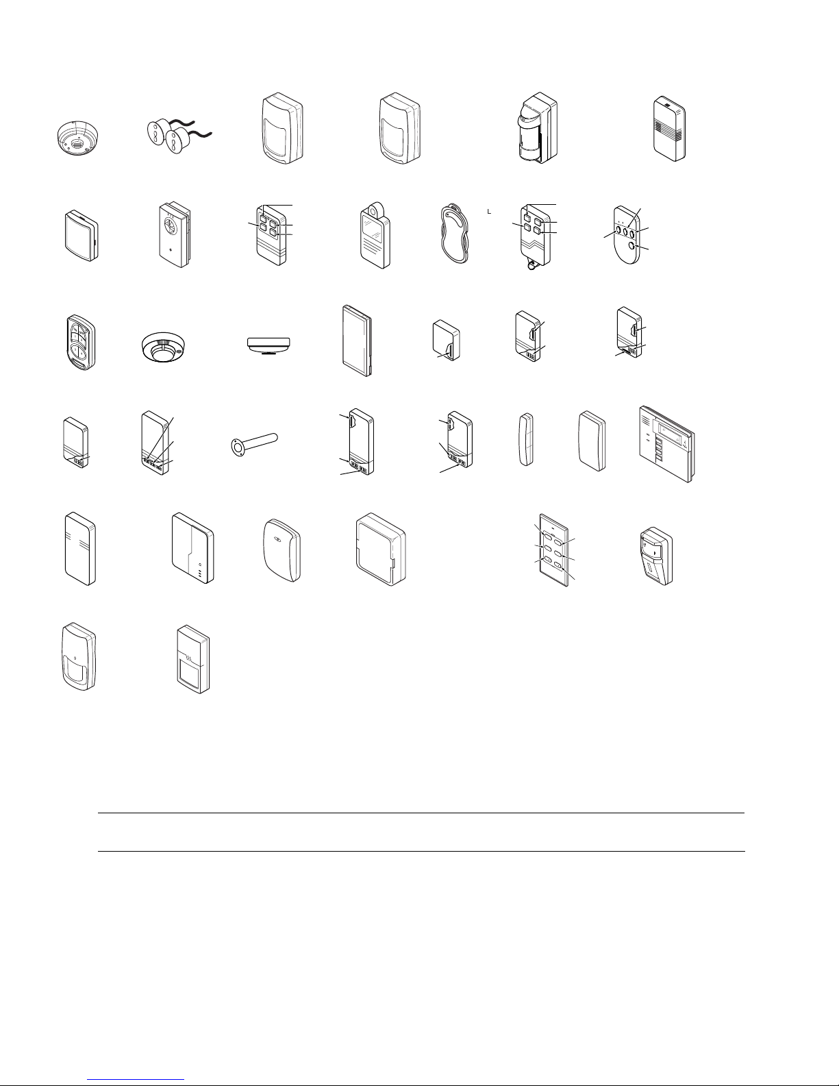
5800 SERIES LOOP NUMBERS
LOOP
58 00 CO
EN RO LL A S " RF"
58 00 SS1
EN RO LL A S " RF"
ON
OFF
21
3
4
58 05 -6
ENROLL AS
"BR"
LOOP 1
(TEMP
SENSOR)
58 16 TEM P
ENROLL AS
"RF"
58 49
ENROLL AS
"RF"
1
5808/5808LST/5808W3
LOOP 1
(SOUND)
58 00 Mic ra
EN RO LL A S " RF"
58 00 WAVE
PR OG RAM
HO US E ID
5806/5806W3/5807
ENROLL AS
"RF"
LOOP 1
(PRIMARY)
LOOP 2
(AUX.
CENTER)
LOOP 3
(AUX.
RIGHT)
58 17
ENROLL AS
"RF"
58 50 (GB D)
ENROLL AS
LOOP 1
YOU MUST
(Green)
(Red)
(Yellow)
"RF"
LOOP 4
ENROLL
THIS
BUTTON
ENROLL AS
ENROLL AS
58 00 PIR -R ES
EN RO LL A S " RF"
58 01
EN RO LL A S
"U R O R"R F"
5809
"RF"
LOOP 1
58 18
"RF"
58 53
ENROLL AS
LOOP 1
LOOP 3
LOOP 2
LOOP 1
LOOP 1
LOOP 2
(REED)
LOOP 3
(TERMINALS)
LOOP 1
(TERMINALS)
ENROLL AS
"RF"
58 00 PIR -C OM
EN RO LL A S " RF"
58 02 MN
ENROLL AS
"UR" OR "RF"
58 11
EN RO LL A S " RF"
58 19
"RF"
5870API
ENROLL AS
LOOP 1
(LOW
SENSITIVITY
LOOP 2
(HIGH
SENSITIVITY)
LOOP 3 (TEMP)
58 00 PIR /
LOOP 4 (TAMPER)
LOOP 1LOOP 1
LOOP 1
ENROLL
LOOP 2
(REED)
LOOP 3
(TERMINALS)
LOOP 1
(INTERNAL
SHOCK
SENSOR
58 19 S (W HS & BR S)
ENROLL AS
LOOP 1
(HIGH
SECURITY)
LOOP 2
(STANDARD
SECURITY)
LOOP 3 (TILT MODE)
LOOP 4 (TAMPER)
"RF"
58 02 MN2
ENROLL AS
"UR" OR "RF"
5814
AS
"RF"
"RF"
LOOP 4
YOU MUST
ENROLL
THIS
BUTTON
ENROLL AS
ENROLL AS
SERIAL #1
SERIAL #1
SERIAL #2
58 00 PIR -O D
EN RO LL A S " RF"
ON
OFF
5804/5804E
ENROLL AS "BR"
LOOP 2
(REED)
LOOP 1
(TERMINALS)
58 16
"RF"
58 20 /58 20 L
"RF"
LOOP 3
AWAY
1
LOOP 4
3
LOOP 3
58 78
ENROLL AS
LOOP 1
(LOW
SENSITIVITY
LOOP 2
(HIGH
SENSITIVITY)
LOOP 3 (TEMP)
LOOP 4 (TAMPER)
LOOP 3
LOOP 2
LOOP 1
FOR LOOP 2
58 21
ENROLL AS
SERIAL #1
STA
LOOP 2
Y
2
SERIAL #1
4
LOOP 1
SERIAL #2
LOOP 2
"BR"
LOOP 2
LOOP
•
3
•
•
•
•
•
•
•
•
•
•
•
•
•
•
•
•
•
•
58 04 BD/ 58 04B DV
ENROLL AS
58 16 MN
ENROLL AS
"RF"
"BR"
LOOP 2
(REED)
LOOP 1
(TERMINALS)
"RF"
ARMED
READY
58 28 /58 28 V
PR OG RAM
58 90 /58 90 PI
ENROLL AS
PROGRAM HOUSE ID
ALTERNATE
POSITION
58 00 RL
SE T
HO US E ID
LOOP 4
YOU MUST
ENROLL
THIS BUTTON
LOOP 1
MIC
MESSAGE
HOUSE ID
LOOP 1
(MOTION)
"RF"
58 94 PI
ENROLL AS
"RF"
5897
ENROLL AS
"RF"
Notes: (1) You must enroll loop 4 on the 5801, 5804/5804E, and 5804BD/5804BDV transmitters, regardless of whether it is used or not.
(2) 5804E encrypted (High-Security) devices must be activated while the system is in Go/No Go Test Mode. Refer to the
transmitter’s installation instructions for complete details. The system will confirm enrollment of the encrypted device by
beeping two times.
(3) The 5806W3 smoke detector must be used in SIA applications.
UL
The 5800RL, 5802MN, 5802MN2, 5804, 5804BD, 5804BDV, 5804E, 5808LST, 5814, 5816TEMP, 5819, 5819S(WHS & BRS),
5828/5828V and 5850(GBD) transmitters are not intended for any UL installations.
- 22 -
5800-002-V0
Page 23

Safewatch QuickConnect Plus Control Defaults
Function Default
*20 Installer code 6321
*21 Quick arm enable 1
*22 Keypad backlight timeout 0
*23 Forced bypass 1
*24 RF house ID code 0,0
*25 Powerline carrier device house code 0
*26 Chime-by-zone 0
*27 Real-time clock display 1
*29 Daylight saving time start/end month 3,11
*30 Daylight saving time start/end weekend 2,1
*31 Single alarm sounding per zone 0
*32 Fire sounder timeout 0
*33 Alarm bell timeout 1
*34 Exit delay 6,0
*35 Entry delay 1 (zone type 01) 3,0
*36 Entry delay 2 (zone type 02) 3,0
*38 Confirmation of arming ding 0
*39 Cross zone timer 0
*40 PABX access code/Call waiting disable --*41 Primary phone number --*42 Secondary phone number --*43 Primary subscriber account number 15,15,15,15
*44 Secondary subscriber account number 15,15,15,15
*46 “Follow Me Reminder” Phone Number --*47 Phone system select 5
*48 Report format for primary/secondary 7,7
*49 Split/dual reporting 0
*50 Burglary abort window 2
*51 Periodic test report 0
*52 First test report offset 2
*53 Sescoa/radionics select 0
*54 Lack of usage notification 0
*55 Reporting channels 0
*56 Enhanced zone programming See *56 table
*57 False alarm options 7
*58 RF jam detection 0
*59 Exit error report code 1
*60 Trouble report code 1,0
*61 Bypass report code 0,0
*62 AC loss report code 0,0
*63 Low battery Report code 1,0
*64 Test report code 1,0
*65 Open report code 0
*66 Arm away/stay report code 0,0
*67 RF transmitter low battery report code 1,0
*68 Cancel report code 1,0
*69 Recent close report code 1
*70 Alarm restore codes 1
*71 Trouble restore report code 1,0
*72 Bypass restore report code 0,0
*73 AC restore report code 0,0
*74 Low battery restore report code 1,0
*75 RF transmitter low battery restore report code 1,0
*76 Test restore report code 1,0
*77 Dynamic Signaling Delay/ Dynamic Signaling Priority 0,0
*78 Programmable Tone Generation Time 0,0
*80 Powerline Carrier Devices See *80 table
*81 Zone lists for devices See *81 table
*84 Assign zone voice descriptors See *84 programming
*86 Multi-mode (E-mail notification) 0
*87 Auxiliary Function/ 1-button paging 0
*88 Pager characters --*89 Event log 80% full report code 0,0
*90 Event logging 3
*91 Alarm audio verification/remote phone control 2
*92 Swinger shutdown 1
*93 Flexible call back 0
*94 Download phone number --*95 Ring detect count for downloading/remote phone control 15
Default Master Code 1,2,3,4
Default Duress Code ---
By activating *96, Field 43, and 44 will be changed to 15, 15, 15, 15.
- 23 -
Page 24
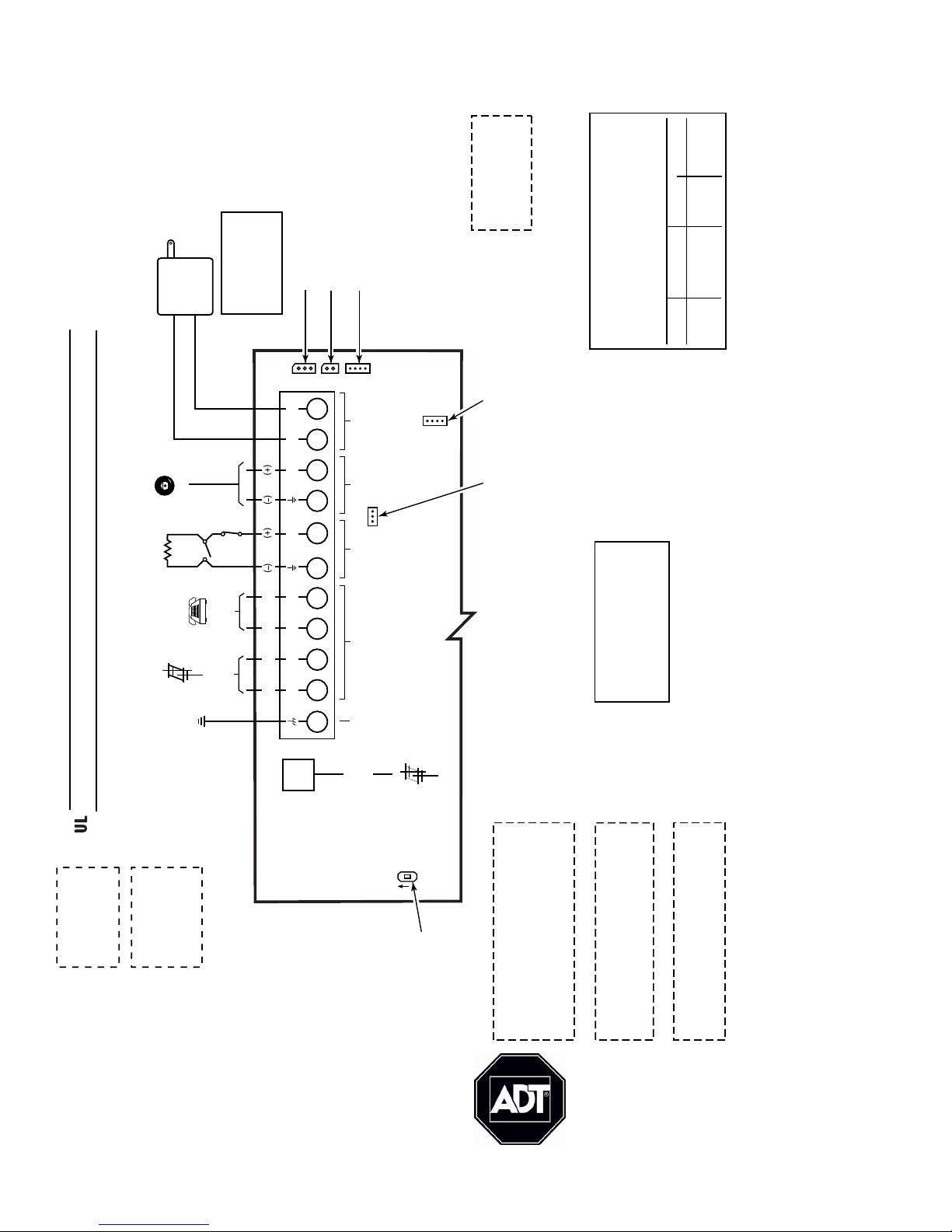
85dB
SIREN
DISABLE
SWITCH
UL INSTALLATIONS
THE MINIMUM WIRE
SIZE USED FOR
TELEPHONE
INSTALLATIONS
MUST BE #26 GAGE
WARNING
TO PREVENT RISK OF
SHOCK, DISCONNECT
TELEPHONE LINE
AT TELECOM JACK
BEFORE SERVICING
THIS UNIT
THIS DEVICE COMPLIES WITH PART 15 OF FCC RULES.
OPERATION IS SUBJECT TO THE FOLLOWING TWO
CONDITIONS: (1) THIS DEVICE MAY NOT CAUSE HARMFUL
INTERFERENCE, AND (2) THIS DEVICE MUST ACCEPT ANY
INTERFERENCE RECEIVED, INCLUDING INTERFERENCE
THAT MAY CAUSE UNDESIRED OPERATION.
THIS EQUIPMENT SHOULD BE INSTALLED IN ACCORDANCE
WITH THE NATIONAL FIRE PROTECTION ASSOCIATION
STANDARDS ANSI/NFPA 70 NATONAL ELECTRIC CODE AND
NFPA 72 NATIONAL FIRE ALARM CODE, CHAPTER 2
(NATIONAL FIRE PROTECTION ASSOC., BATTERY MARCH
PARK, QUINCY, MA 02169). PRINTED INFORMATION
DESCRIBING PROPER INSTALLATION, EVACUATION
PLANNING AND REPAIR SERVICE IS TO BE PROVIDED WITH
THIS EQUIPMENT.
LYNX PLUS SERIES ALSO COMPLIES WITH THE FOLLOWING:
CANADIAN STANDARDS ASSOCIATION (CSA) C22.1,
CANADIAN ELECTRICAL CODE, PART 1, SAFETY STANDARD
FOR ELECTRICAL INSTALLATIONS AND CAN/ULC-S540
INSTALLATION OF RESIDENTIAL FIRE WARNING SYSTEMS.
QUICKCONNECT PLUS SUMMARY OF CONNECTIONS
THE QUICKCONNECT PLUS CONTROLS ARE
COMPATIBLE WITH THE FOLLOWING
INTEGRAL RECHARGEABLE BATTERY PACKS:
REPLACE EVERY FOUR YEARS
P/N LYNXRCHKIT-SC
P/N LYNXRCHKIT-HC
P/N LYNXRCHKIT-SHA
CIRCUIT
(ZONE)
CONTROL UNIT
DELAY-SEC
SMOKE DETECTOR
MODEL DELAY-SEC
THIS UNIT MAY BE PROGRAMMED TO INCLUDE AN ALARM
VERIFICATION FEATURE THAT WILL RESULT IN A DELAY OF THE
SYSTEM ALARM SIGNAL FROM THE INDICATED FIRE CIRCUITS.
THE TOTAL DELAY (CONTROL UNIT PLUS SMOKE DETECTORS)
SHALL NOT EXCEED 60 SECONDS. NO OTHER INITIATING
DEVICES SHALL BE CONNECTED TO THESE CIRCUITS UNLESS
APPROVED BY THE LOCAL AUTHORITY HAVING JURISDICTION.
WARNING
5806 10 seconds30 seconds
02 - 25
ZT16
1000-200-SOC-V0
FCC ID: CFS8DLLYNXPLUS
(LYNX PLUS SERIES)
COMPLIES WITH FCC RULES,
PART 68 FCC REGISTRATION
No. 5GBUSA-25623-AL-E
RINGER EQUIVALENCE: 0.6B
NOTE
USE ONLY THE
K10145WH/K10145X10
OR K10145CN CLASS 2
TRANSFORMERS
PROVIDED
EXTERNAL SOUNDERS AND POWERLINE CARRIER DEVICES HAVE NOT BEEN EVALUATED BY UL.
WEEKLY TESTING IS
REQUIRED TO ENSURE
PROPER OPERATION
OF THIS SYSTEM
POWER SHUTDOWN NOTE: AT 6.0VDC THE SYSTEM WILL NOT OPERATE.
PREMISES
TELEPHONE
INCOMING
TELEPHONE
LINE
6-14VDC
120mA max.
BELL
HARD
WIRED
ZONE
ALL OUTPUT CIRCUITS ARE POWER LIMITED.
1
2
3
4
86
5
11
7
10
PHONE
ZONE
SOUNDERS
AC
EARTH
GROUND
EARTH
GROUND
9
SUPER HIGH-CAPACITY
BATTERY CONNECTOR
GSML/GSMVL
COMMUNICATIONS PORT
STANDARD/HIGH-CAPACITY
BATTERY CONNECTOR
TO 24HR 110VAC
UNSWITCHED
OUTLET
K10145WH/K10145X10
OR K10145CN PLUG-IN
TRANSFORMER
9VAC, 25VA
RING
TIP
RING
TIP
INCOMING
PHONE
LINE
8
POS
JACK
POWERLINE
CARRIER
DEVICE
CONNECTOR
GSMVL
AUDIO
CABLE
CONNECTOR
ON
AC
AC
SOUND
OUT
HWZ
T
R
T
R
2k
OHMS
EOLR
Ê800-03859-4V2tŠ
800-03859-4V2 11/10 Rev. A
ADT Security Services, Inc.
One Town Center Road
Boca Raton, FL 33486
Copyright © 2010
 Loading...