

Page 1
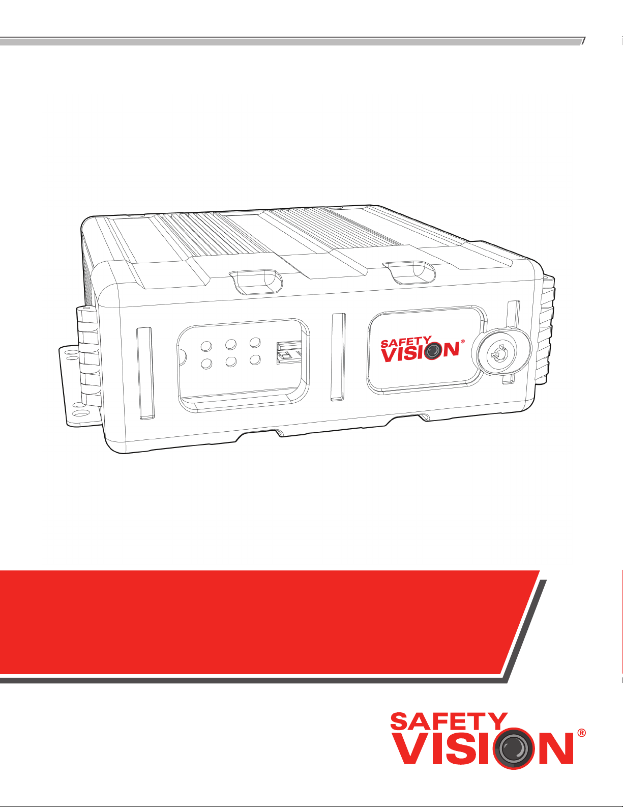
OBSERVER™ 4000
USER GUIDE
Page 2

OBSERVER 4000 USER GUIDE
Important Notices
Title: Observer™ 4000 User Guide
Document Version: 1.0
Firmware version: X01-4-T570721
Safety Vision attempts to provide information contained
in this manual based on the latest product information
available at the time of publication. However, because of
Safety Vision’s policy of continual product improvement,
Safety Vision reserves the right to amend the information in
this document at any time without prior notice.
This material is condential and the property of Safety
Vision. It is shared with your company for the sole purpose
of helping you with the operation of the described
equipment.
Safety Vision makes no warranty of any kind with regard
to this material, including, but not limited to, the implied
warranties of merchantability and tness for a particular
purpose. Safety Vision shall not be liable for errors
contained herein or for incidental or consequential damages
in connection with the furnishing, performance, or use of
this material.
Safety Vision expressly disclaims all responsibility and
liability for the installation, use, performance, maintenance,
and support of third-party products. Customers are advised
to make their independent evaluation of such products.
No part of this document may be photocopied, reproduced,
or translated to another language without the prior written
consent of Safety Vision.
Safety Vision® is a registered trademark of Safety Vision, LLC. All
other products or name brands mentioned in this document are
trademarks of their respective owners. For more information
about Safety Vision and its products, go to www.
safetyvision.com or call 800-880-8855.
Page 3

OBSERVER 4000 USER GUIDE
Table of Contents
Components 2
Main Wiring Diagram 4
Installation 5
SD Card Removal/Insertion 6
Remote Control 7
Live View 8
Menu Navigation 8
Video Playback 9
Exporting Video Files 11
Conguration 12
System Menu 12
Record Menu 21
Event Menu 28
1
Peripheral Menu 36
System Information 38
Appendix A: Specications 41
Appendix B: Dimensions 42
Page 4
OBSERVER 4000 USER GUIDE
2
OBSERVER 4000 USER GUIDE
Components
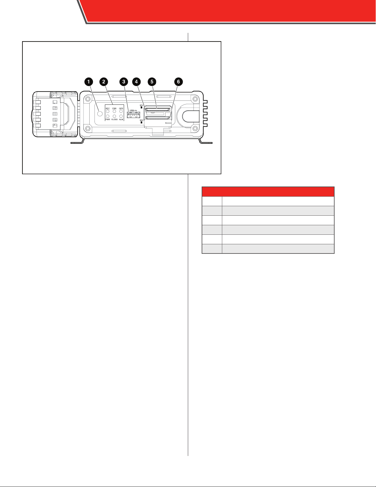
1 - IR Remote Sensor - The IR Remote Sensor receives
signals from the DVR Remote Control.
2 - Status LEDs - The Status LEDs illuminate to display
the current status of the DVR. See chart at left.
3 - USB Port - Insert a USB ash drive to download events
quickly without having to remove the SD card or hard drive,
or upload rmware updates.
4 - SIM Card Slot - Not used.
5 - Primary SD Card Slot - Insert an SD card into the
slot until it clicks. To remove the SD card, briey press it in
until it ejects.
6 - Mirror/Secondary SD Card Slot - Insert an SD
card into the slot until it clicks. To remove the SD card,
briey press it in until it ejects. This SD card can be used for
mirror recording or as a secondary storage device once the
primary SD card is full.
STATUS LEDS
REC
PWR
ERR
VLOSS
GPS
ALM
One or more cameras is detached or malfunctioning
Solid - GPS searching for signal/Flashing - GPS has locked on
DVR is recording video
DVR is receiving power
Error may have occured
Event/alarm has occured
For further information regarding
the conguration of the DVR, see the
Conguration section.
Page 5
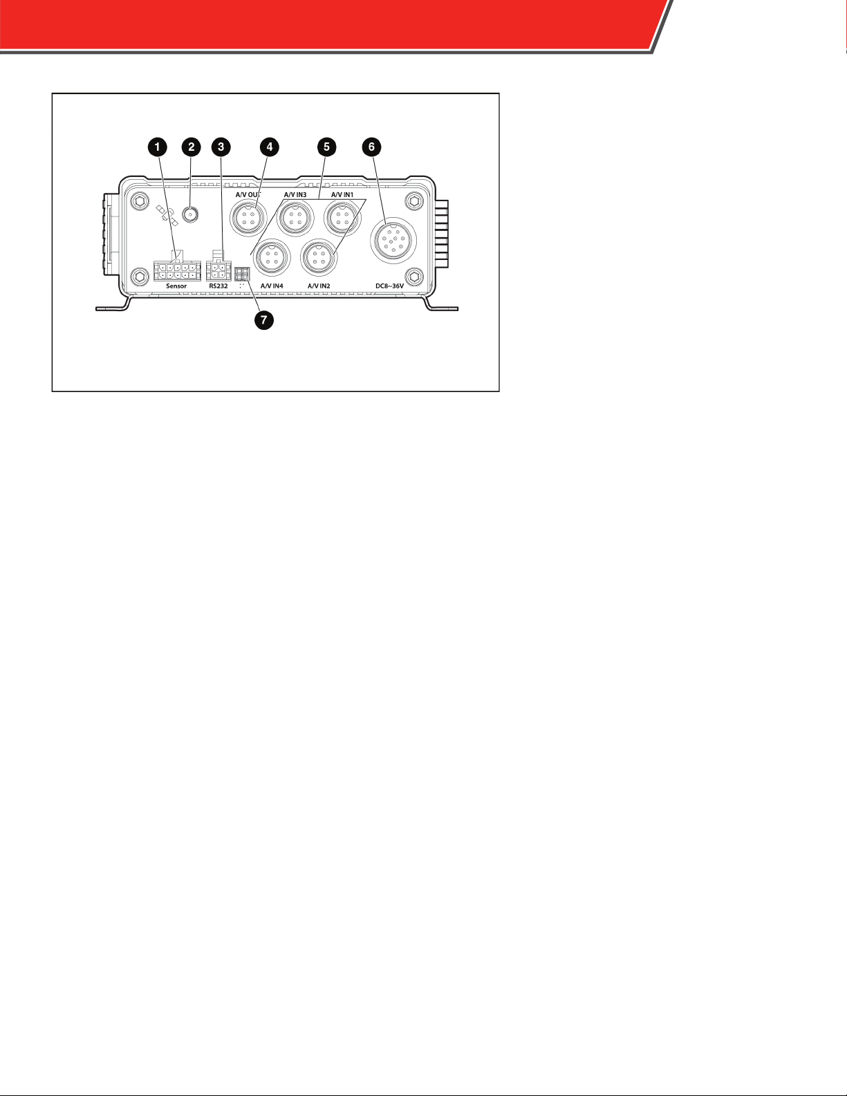
1 - Sensor Port - Connection for the 4000-Trigger sensor harness.
3
2 - GPS Antenna Port - Connection an external GPS antenna.
3 - RS232 Port - Connection for optional RS232 accessories such as a Garmin GPS
antenna.
4 - A/V OUT Port - Connection for 4000-A/VOUT-ADA to an external monitor.
5 - A/V IN 1-4 Ports - Connection for SV-A/V-INPUTADA to cameras.
6 - Power Port - Connection for the 41-PWRHRNS main power harness.
7 - Debug Port - For Service Technician use only.
Page 6
4
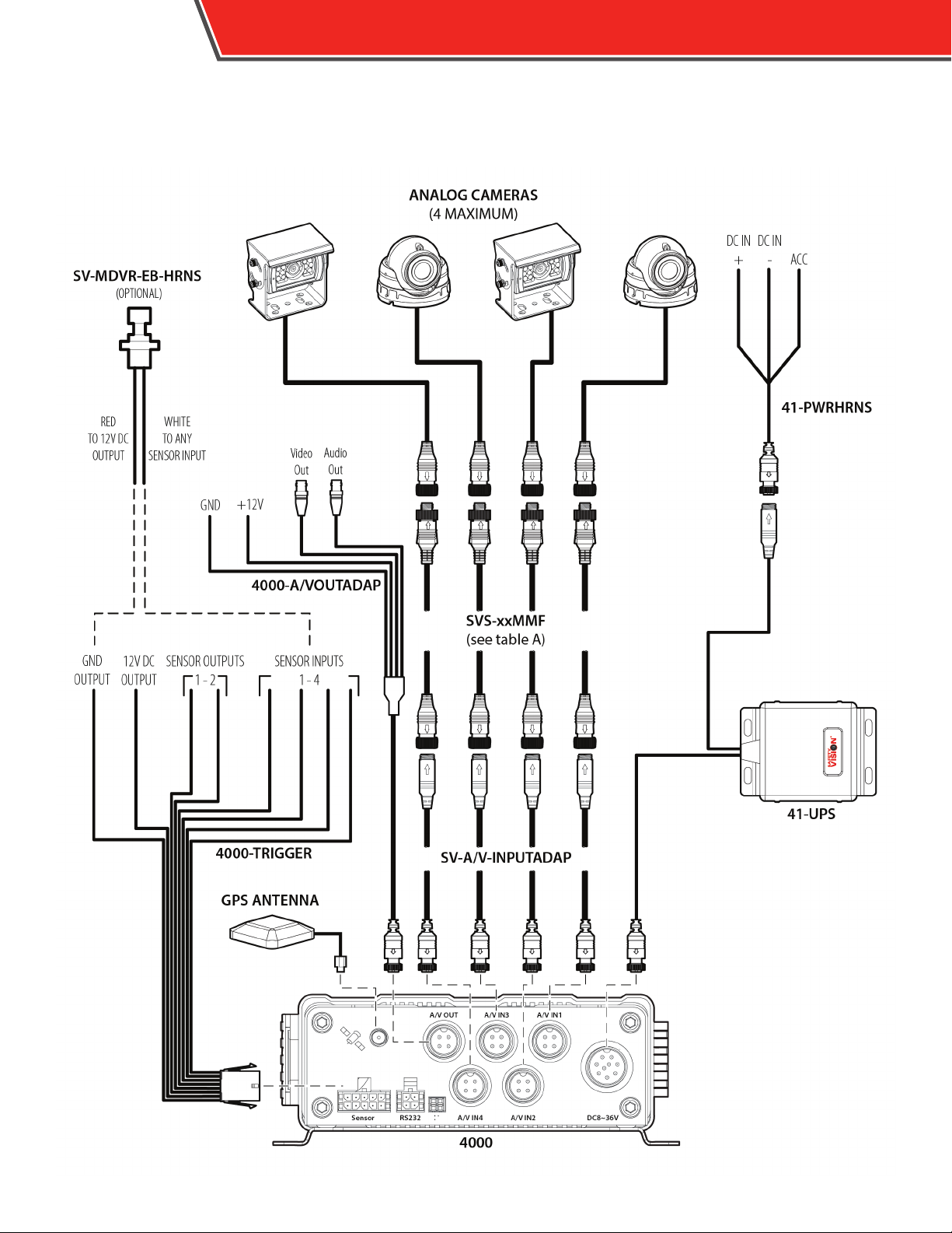
Main Wiring Diagram
OBSERVER 4000 USER GUIDE
Page 7
OBSERVER 4000 USER GUIDE
5
Tab l e A
Cable Length
SVS -3MMF
SVS-5MMF
SV S-10 MMF
SV S-15 MMF
SVS-20MMF
10’
16’
33’
49’
65’
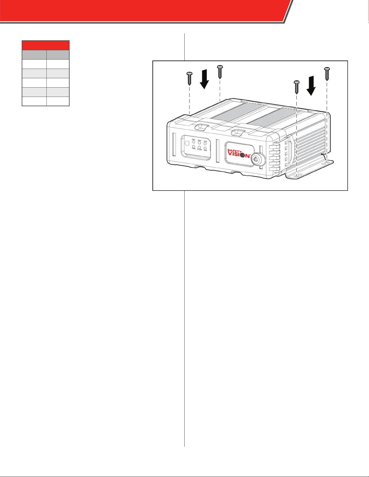
Installation
Flat Mount
Secure the DVR to the surface with self-tapping
screws or rivets.
Ensure that the front panel of the DVR
remains accessible and there is a minimum
2.5 inches of clearance for cables.. Do not
install the DVR in an area of the vehicle cabin
that could interfere with the safe operation
of the vehicle.
Page 8
6
SD Card Removal/Insertion
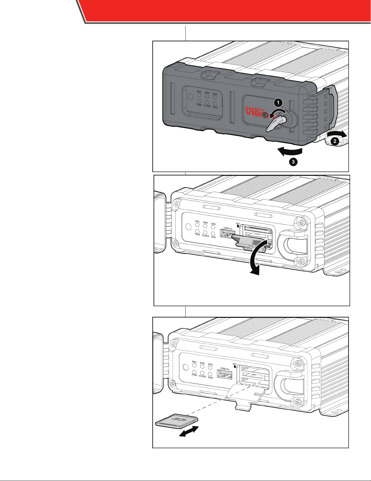
Do not force the SD card into the slot
upside down or backwards.
Ensure the SD card’s write protection
slider is in the “unlocked” position.
Do not remove the SD card until the
DVR is turned o.
1. Insert the key into the faceplate
lock and turn it counter-clockwise.
2. Release the faceplate latch.
3. Open the faceplate.
Opening the faceplate automatically
turns the DVR o.
4. Wait until the DVR has completely
powered down (PWR status LED
has turned o).
5. Flip down the SD card slot door.
6. Insert an SD card into the SD card
slot label-side up, with the notch to
the right, until it clicks in place.
To remove the SD card, press the SD
card as far as it will go in the slot, then
allow it to “spring” out.
OBSERVER 4000 USER GUIDE
Page 9
Remote Control
OBSERVER 4000 USER GUIDE
7
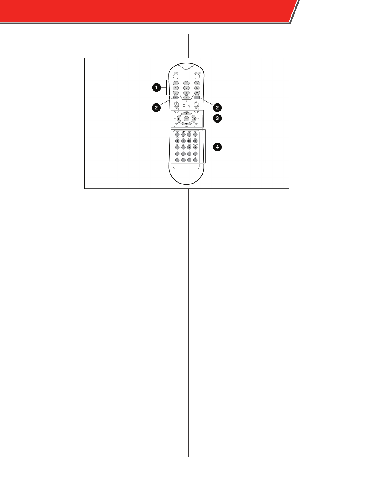
The Observer remote control is used to navigate through
the conguration menus or to control video playback on an
external monitor. Point the remote control at the IR receiver
on the front panel of the Observer to make selections.
Power - Use this key to power the Observer on or o.
DO NOT power o the unit while the ignition is on, otherwise
the unit will not automatically power on when ignition is
reapplied.
Login/Lock - Quickly access the login screen or secure the
unit when already logged in. Login values can be set in the
conguration menu.
1 - Numeric Keypad - Use the numeric keypad to
input numerical values when conguring the system.
Additionally, you can use the 1, 2, 3, and 4 keys to display
that numbered video channel during video playback. Press
the 0 key to switch between displaying individual channels
and a quad view.
2 - + and - Keys - Use the + and - keys to increase or
decrease values by one.
Video - Switch between VGA output and the front composite
external monitor output.
Brightness, Contrast, and Color - Press this key repeatedly
to toggle between brightness, contrast, and color options for
each individual channel. Use the + and - keys to adjust each
value.
Setup - Quickly access the conguration menu. Login may
be required.
Exit - Quickly return to the previous menu while viewing
conguration menus. Pressing this key on the main
conguration menu returns to the live view.
Pause/Step - During video playback, press this key to pause
the video. Press this key again to advance video playback by
one frame.
Play - Press this key to resume regular speed video playback
when video is paused or stopped.
Slow - Press this key to slow down video playback.
3 - Navigation Buttons - Use the four arrow keys to
navigate between input elds or menu selections when
conguring the system. Use the Enter key in the center of
the arrow keys to make selections. During video playback
the left and right arrow keys can be used to rewind or fastforward. Press the Enter key while viewing the live view to
display a comprehensive status screen.
4 - Additional Remote Control Keys
VGA - Switch the output mode of the external monitor to
VGA1, VGA2, or VGA3.
GoTo - Press this key to quickly access video recorded at a
certain time. When playing back video, press this key and
input the desired time. Press Play to begin video playback.
Stop - Press this key to manually stop video recording.
Record - Press this key to manually begin recording again
once it has stopped.
Page 10
8
OBSERVER 4000 USER GUIDE
Live View
Attach an external monitor to the A/V OUT port while the DVR is on to view the
Live View.
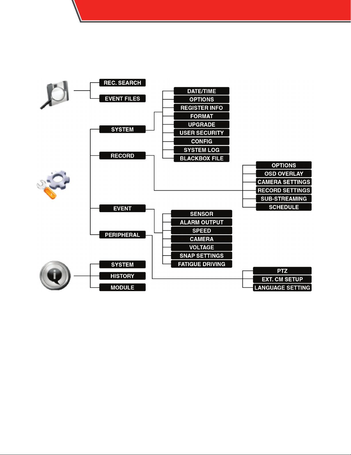
Menu Navigation
Press the Setup or Login/Lock keys on the remote control while an external monitor is connected to access the DVR menu.
You must login with a password using the number keys on the remote if one has been set in the User Security conguration
menu.
The default unit number is 0 and the default password is 88888888.
For more information on setting the device password, navigate to Conguration, then System, then User Security.
Use the up and down arrow navigational keys to switch between the Video Playback, Conguration, and Information icons and
display their associated menus.
Use the right arrow key to select and expand successive menu options. Use the left arrow key to return to collapse the current
menu option and return to the previous menu option.
The DVR does not record video when menus are displayed.
Page 11
OBSERVER 4000 USER GUIDE
Video Playback
To view recorded video with an attached external monitor,
use the remote to access the menu, then select the rst icon.
The All Files and Event Files options appear.
Select the All Files option to review all recorded video
stored.
Select the Event Files option to review only video marked as
events.
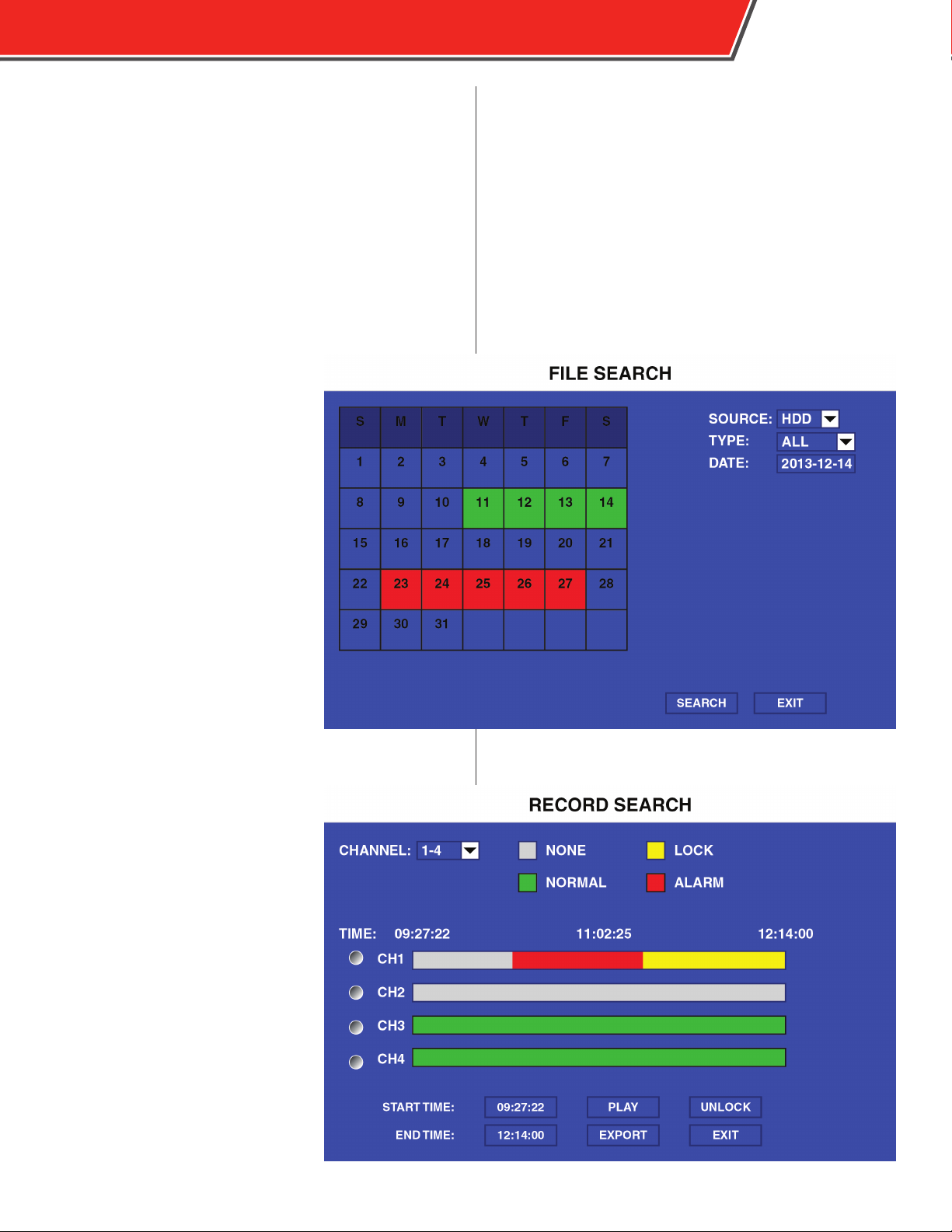
All Files
Use the elds on the right side of the
screen to select the appropriate criteria
of the recorded video for which you want
to search. The select SEARCH. Available
video appears on the calendar display.
Green days indicate normal video was
recorded, red days indicate event les
were recorded. Use the remote control
to select the day and press the enter key.
9
The Record Search screen displays. Select channels 1-4 or channels 5-8 in the
CHANNEL eld. For each channel, the
type of video recorded is indicated by
dierent colors. Use the START TIME and
END TIME elds to display the selected
time of day. When the video you are
searching for is displayed, select PL AY,
EXPORT, or LOCK/UNLOCK.
Page 12
10
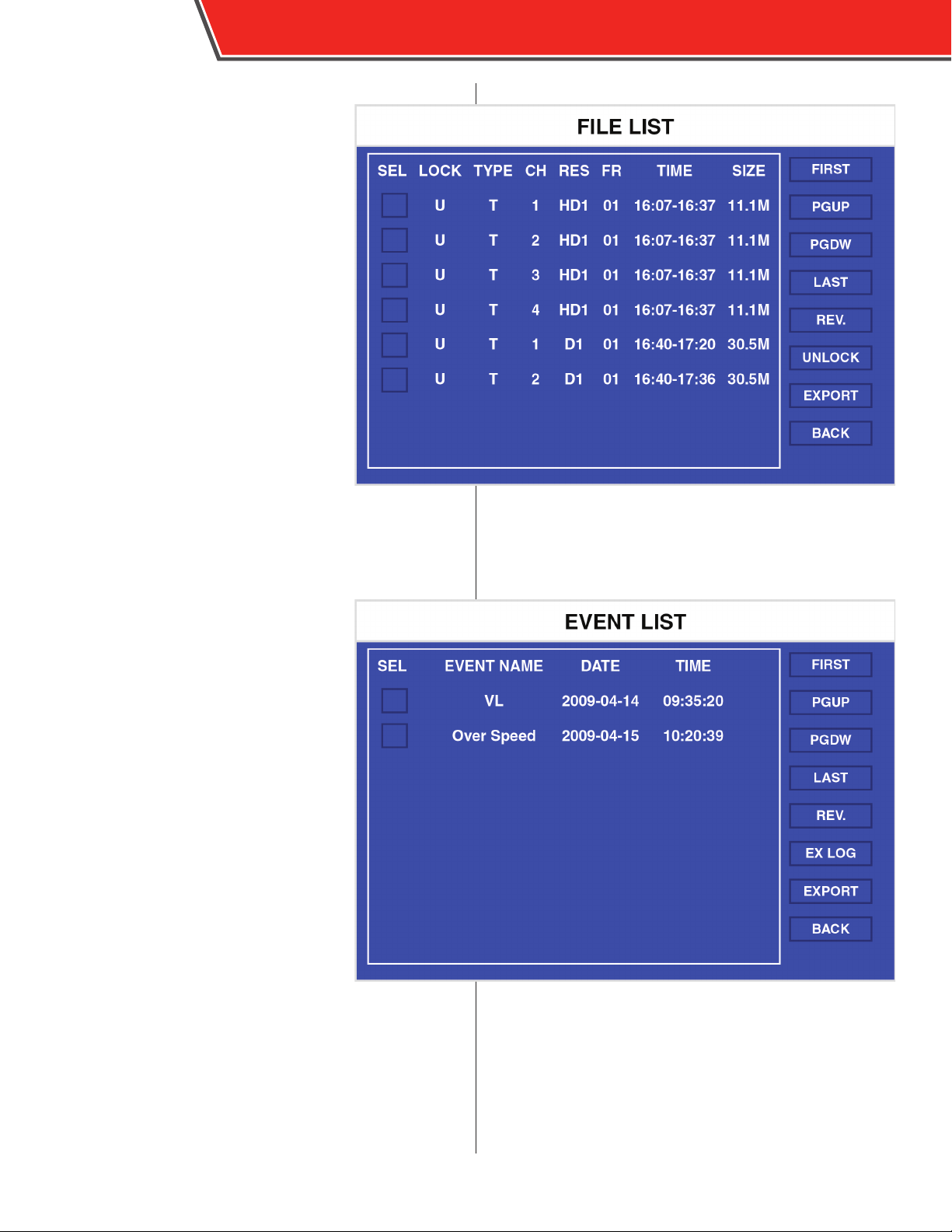
Event Files
SEL: Use the arrow and Enter keys on the
remote control to select or unselect each
le. Selected les can then be exported.
Multiple les can be selected at one time.
EVENT NAME: Displays the type of event
that triggered the video recording.
DATE: Displays the date on which the video
was recorded.
TIME: Displays the time the video recording
started.
FIRST, PGUP, PGDW, LAST: Use the arrow
and Enter keys to select these options to
scroll through screens of the displayed
les (if there are more les than can be
displayed on one screen).
OBSERVER 4000 USER GUIDE
Page 13
Exporting Video Files
Video les can be exported to a USB
thumb drive inserted into the USB port
on the front of the DVR.
To manually export video les, use the
following procedure:
1. Select each le you want to export
in the SEL column.
2. Insert a USB thumb drive into the
USB port on the front panel of the
DVR.
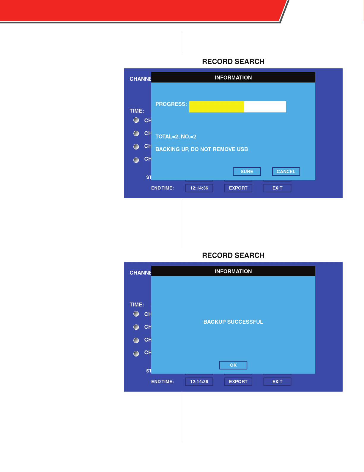
3. Select the Export option on the
right side of the screen.
A Remark window appears.
4. Select Sure.
A progress bar appears, as well as the
total number of les being exported.
5. When the “Backup Successful”
message appears, select OK.
6. Remove the USB thumb drive.
OBSERVER 4000 USER GUIDE
11
To automatically export alarm video les recorded the same
day as the present, use the following procedure:
1. Ensure ON is selected in the EVENT FILES AUTO-
EXPORT (USB) eld in the General
menu (see page 15).
2. Insert a USB thumb drive into the
USB port on the front panel of the
DVR.
3. Press the F1 key on the remote
control.
A message appears to indicate video
is automatically exporting to the
USB drive. If no alarm video les are
present, a message will appear.
For video to be marked as alarm,
the recording must be initiated by a
sensor congured as an alarm. For
more information about conguring a
sensor as an alarm, see page 33.
4. When the “Backup Successful”
message appears, select OK.
5. Remove the USB thumb drive.
If the amount of video being
downloaded exceeds the capacity of the USB thumb
drive being used, a prompt appears requesting that an
additional thumb drive be inserted to conclude the export.
Exported les are saved on the root directory of the USB
thumb drive. Files are titled rst by Unit ID, then Alarm Log,
then the date recorded.
Page 14
12
OBSERVER 4000 USER GUIDE
Conguration
Select the Conguration icon to display the System, Record,
Network, and Event menus.
These menu options allow you to congure how the DVR
operates, in addition to setting passwords and updating the
rmware.
System Menu
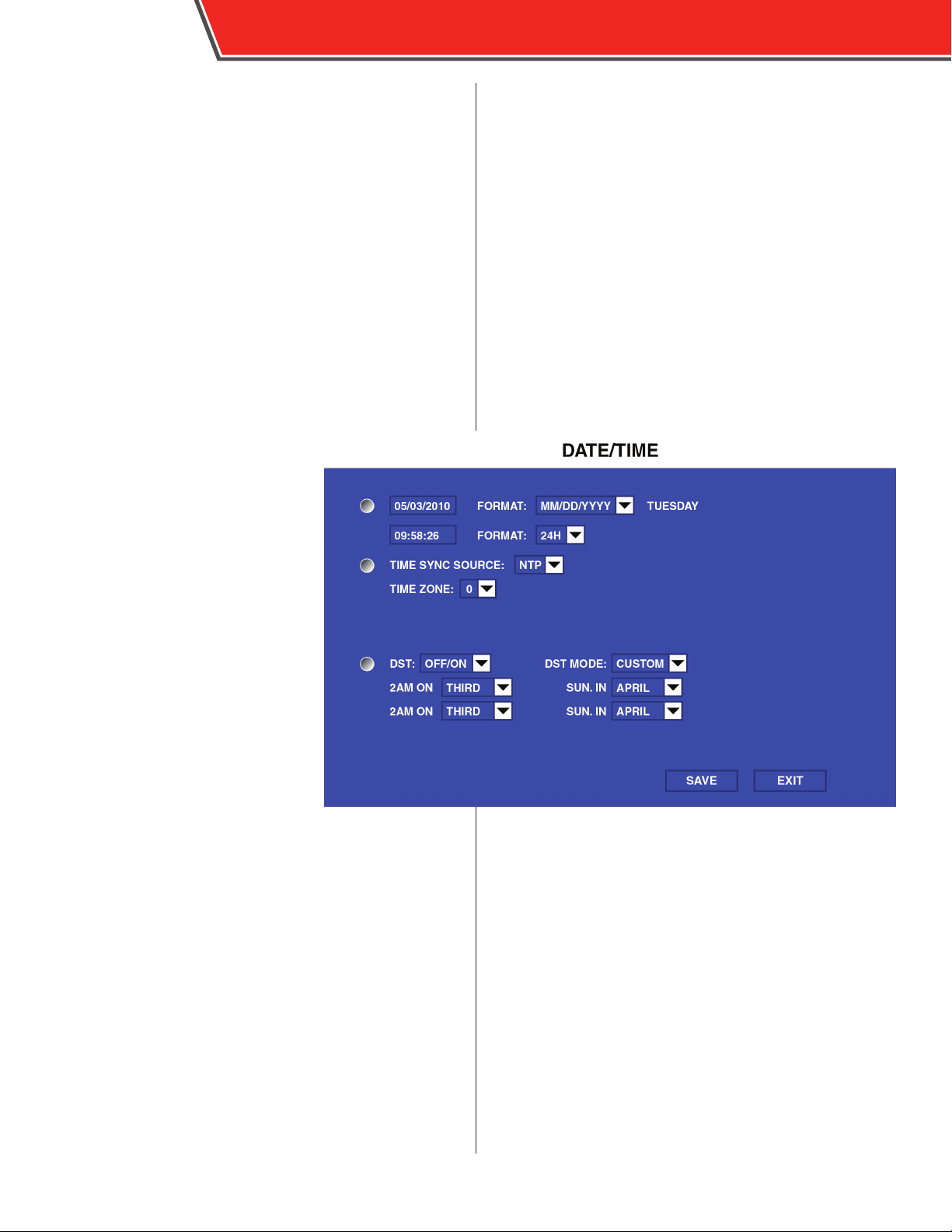
Date/Time
The Date/Time menu determines the
system time that appears on recorded
video.
Date: Use the number keys on
the remote to set the current date
manually.
FORMAT: Select from middle endian
(MM/DD/YYYY), little endian (DD/MM/
YYYY), or big endian (YYYY-MM-DD)
date formats.
Time: Use the number keys on
the remote to set the current time
manually.
FORMAT: Select from 12 hour (12H) or
24 hour (24H) time formats.
TIME SYNC SOURCE: Select Global
Positioning System (GPS) or manual
(NONE).
TIME ZONE: Select how many hours the local time zone is
deviated from GMT. (In the United States, Eastern is “-5”,
Central is “-6”, Mountain is “-7”, and Pacic is “-8”.)
DST: Turn Daylight Savings Time adjustments on (ON) or o
(OFF).
DST MODE: Only available when DST is set to ON. Select
AUTO to adjust the time automatically at 2:00 AM on
the selected Sunday in March and the rst Sunday in
November, or select CUSTOM to select which Sundays in
which months.
Page 15
OBSERVER 4000 USER GUIDE
Options
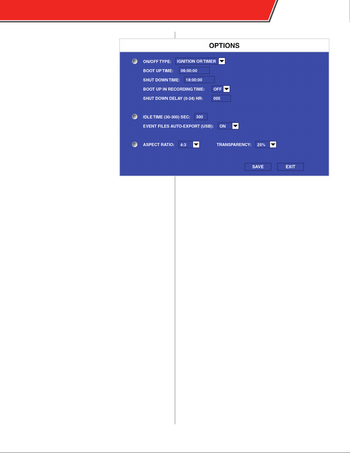
The General menu determines the
behavior of the DVR upon start up
and shutdown, in addition to other
controls.
ON/OFF TYPE: Select TIMER to display
the START UP TIME, SHUT DOWN
TIME, and BOOT UP ON SCHEDULE
elds. This option automatically
starts and shuts down the DVR at the
specied time. Select the IGNITION
option to power the DVR only when
the vehicle starts. This displays the
SHUT DOWN DELAY MIN eld. Select
TIMER OR IGNITION to include both
types of start up and shutdown
parameters.
(ON/OFF TYPE: TIMER)
BOOT UP TIME: Use the number keys
on the remote control to manually enter the time the DVR
starts up each day.
SHUT DOWN TIME: Use the number keys on the remote
control to manually enter the time the DVR shuts down each
day.
AUTO BOOT UP ON SCHEDULE: Select ON to begin
recording automatically upon start up. Select OFF to require
recording be manually triggered.
13
When the ON/OFF TIME eld is set to
TIMER, the DVR automatically shuts
down after ve minutes when it is
turned on outside of the time specied.
To turn this feature o, enter this menu
and select IGNITION in the ON/OFF
TYPE eld.
(ON/OFF TYPE: IGNITION)
SHUT DOWN DELAY MIN: Use the number keys on the
remote control to manually enter the time (in minutes)
that the DVR continues to record after the vehicle has been
powered down.
IDLE TIME SEC: Use the number keys on the remote control
to enter the time (in seconds) that the conguration menus
display without input before automatically exiting to the live
view.
EVENT FILES TO AUTO-EXPORT (USB): This eld is not
currently active.
ASPECT RATIO: Select 4:3 or 16:9 to match the aspect ratio
of the external monitor.
TRANSPARANCY: Select the level of transparency of the onscreen menus.
Page 16
14
Register Info
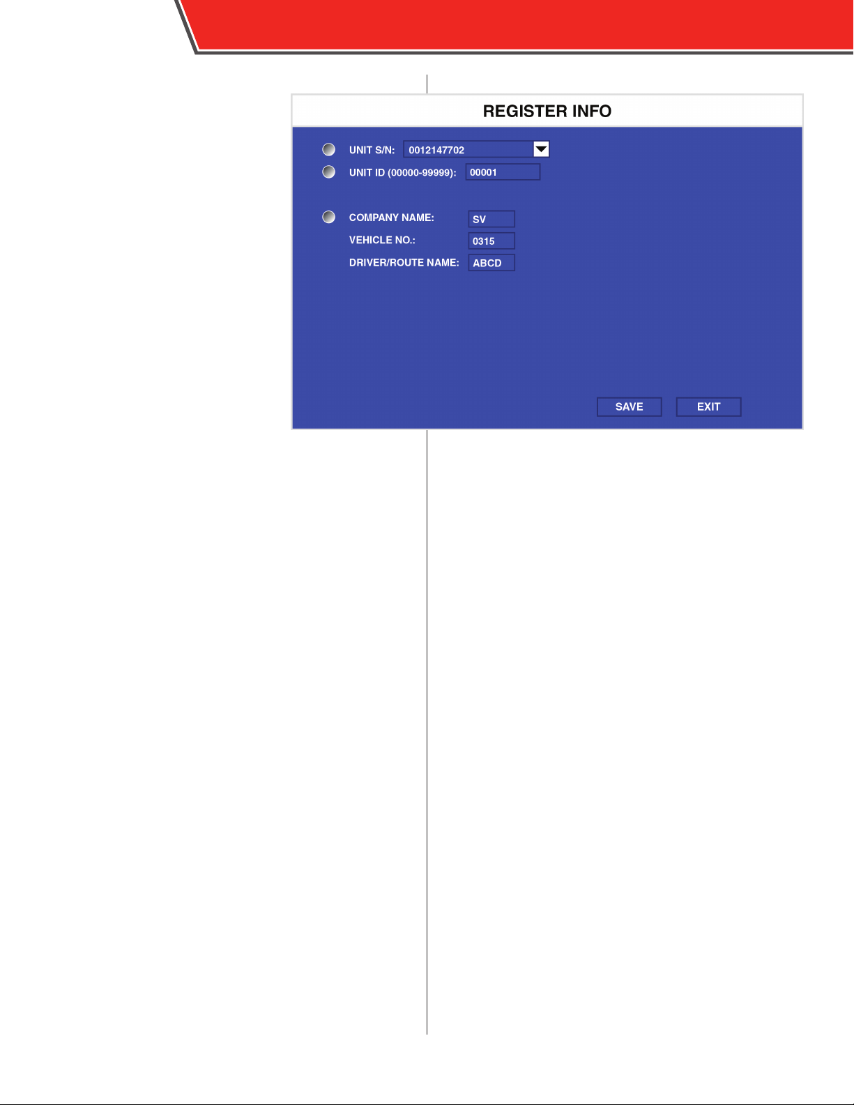
The Register menu includes the
assorted serial numbers and names
unique to the DVR for identication.
UNIT S/N: The DVR’s serial number.
This number is unique and cannot be
changed.
UNIT ID: The DVR’s identifying
number. Use the number keys on
the remote control to input a unique
number ranging from “00000” to
“99999”.
COMPANY NAME.: Use the arrow keys
on the remote control to enter the
name of the agency to which the DVR
belongs.
VEHICLE NO.: Use the number keys
on the remote control to enter the
number of the vehicle in which the
DVR is installed.
DRIVER/ROUTE NAME: Use the arrow keys on the remote
control to enter the driver’s name and/or their route name,
up to 5 characters.
OBSERVER 4000 USER GUIDE
Page 17

Format
Formatting a device erases all existing
data, including recorded video.
Use the following procedure to format
a device:
1. Use the arrow keys on the
remote control to select a device
from the drop-down menu.
Available devices include SD
(inserted SD card), or USB (inserted
USB ash drive).
2. Select OK.
A Warning message appears.
3. Select OK.
4. The format process begins.
When nished, the DVR restarts
automatically.
OBSERVER 4000 USER GUIDE
15
Formatting a device erases all data,
including recorded video.
Use with caution.
Page 18
16
Upgrade
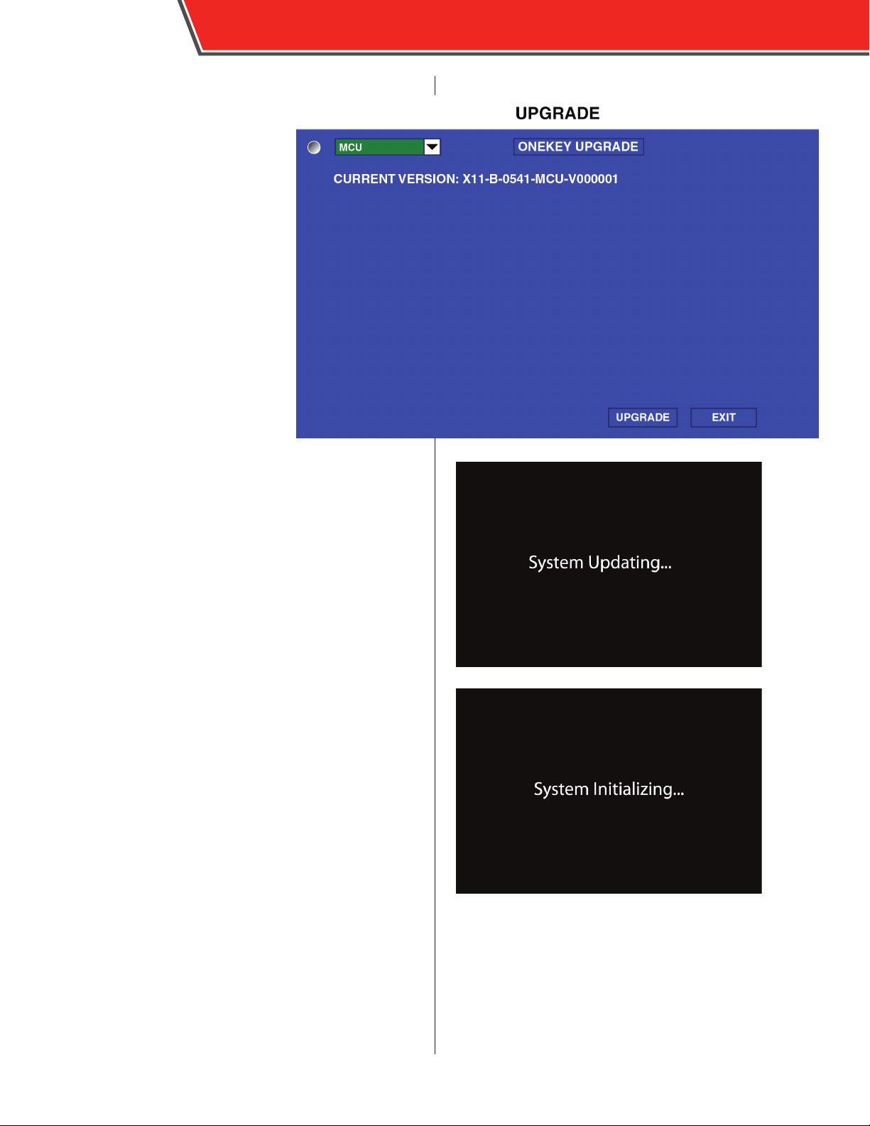
Periodically Safety Vision releases
new rmware updates for the DVR to
increase functionality and features.
OBSERVER 4000 USER GUIDE
Use the following procedure to update the DVR rmware:
1. Obtain the rmware update le
from Safety Vision Technical Support.
2. In the root directory of a USB ash drive create a
folder titled dvrupgrade.
3. Place the rmware update le in the dvrupgrade
folder.
4. Insert the USB ash drive in the front USB port of the
DVR.
5. Access the Upgrade menu.
6. Ensure FIRMWARE is selected in the drop-down
menu.
7. The MCU update function is not active at this time.
8. Select UPGRADE.
The update process begins.
The DVR rst checks for an appropriate upgrade le. If one
is detected, it automatically restarts.
Upon restarting, the DVR displays “System Updating...” on
the external monitor while it installs the upgrade.
When complete, “System Initializing...” is displayed, and
the DVR starts as normal.
The rmware update has been successfully installed and it
is safe to remove the USB ash drive.
The rmware can only be updated to
a version more current the rmware
currently installed.
Page 19
OBSERVER 4000 USER GUIDE
User Security
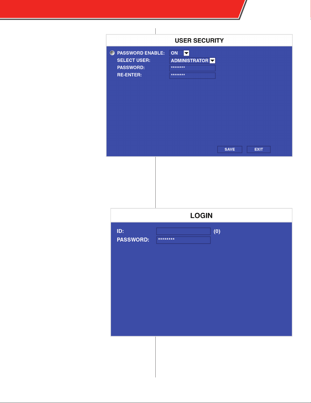
The User Security menu controls the
password needed to access the DVR
menus.
PASSWORD ENABLE: Select ON to
require a password to access the DVR’s
menus; select OFF to disable this
feature and allow free access.
SELECT USER: Select a user level to set
a password for:
- ADMINISTRATOR: has full access
rights, including ability to change
passwords, format storage media, and
export or delete the system log
- POWER USER: same as
ADMINISTRATOR rights, but cannot
change passwords, format storage
media, or export or delete the system
log
- USER: may only view video and video logs (cannot access
conguration menus)
PASSWORD: Enter an eight-digit password with the number
keys on the remote control for the selected user level.
RE-ENTER: Enter the same eight-digit password as you
did in the above eld to conrm it is the
password you want to set. If the password
is dierent, an error message appears.
17
The default unit number is 0 and the default
password is 88888888.
When ON is selected in the PASSWORD
ENABLE eld, the User Login screen
appears when attempting to enter the DVR
menus. Enter “0” in the ID eld, then enter
the assigned password.
Page 20
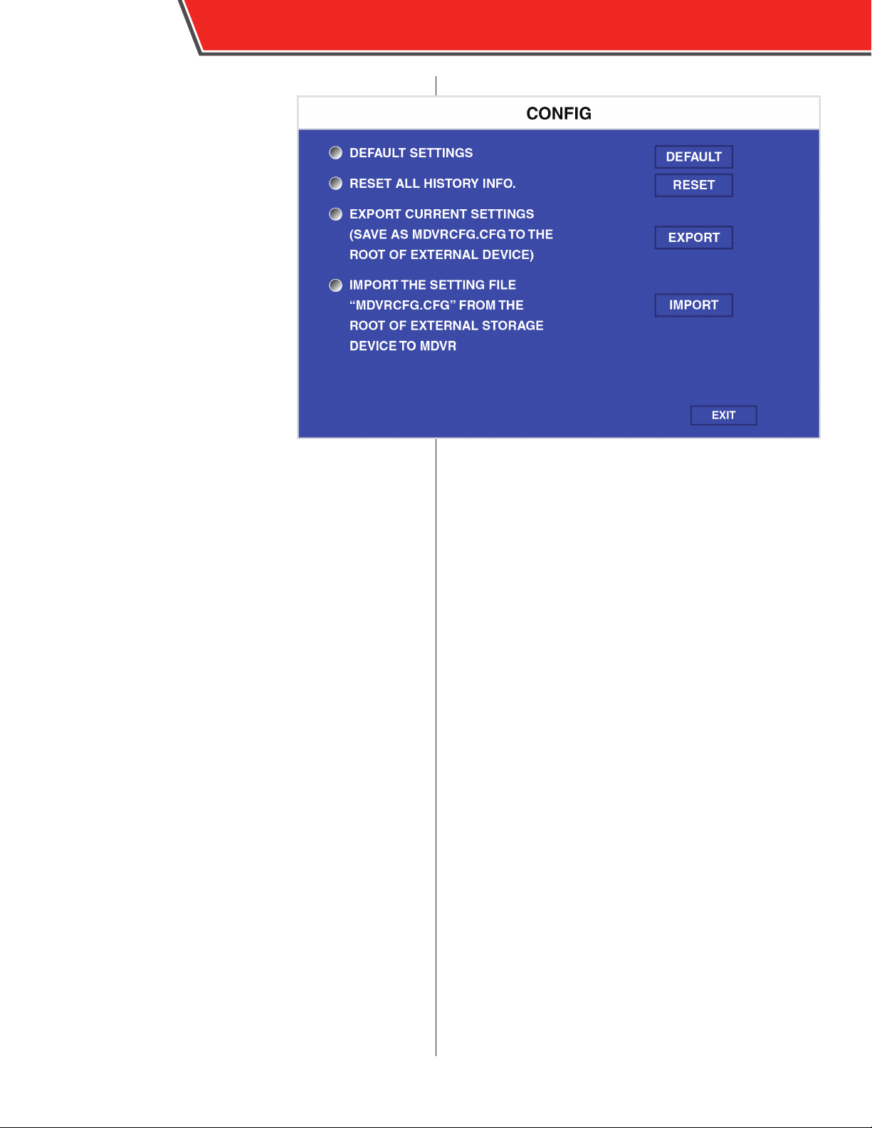
18
Cong
The Cong menu allows you to export
to or import from a USB drive all of the
DVR’s settings, which is useful when
conguring multiple units in the same
manner or creating a backup.
DEFAULT SETTINGS: Select RESTORE
to revert all settings tot he factory
defaults.
RESET ALL HISTORY INFO: Select
RESET to erase all stored data in the
History menu in System Information.
EXPORT CURRENT SETTINGS: To
export all of the current settings to a
USB ash drive, insert one in the front
USB port and select EXPORT. The
settings are automatically saved as
DVRcfg.cfg on the root directory of the
USB ash drive.
IMPORT SETTING FILE: To import
a settings le, ensure the DVRcfg.cfg le is on the root
directory of a USB ash drive, insert it into the front USB
port, and select IMPORT.
OBSERVER 4000 USER GUIDE
Page 21
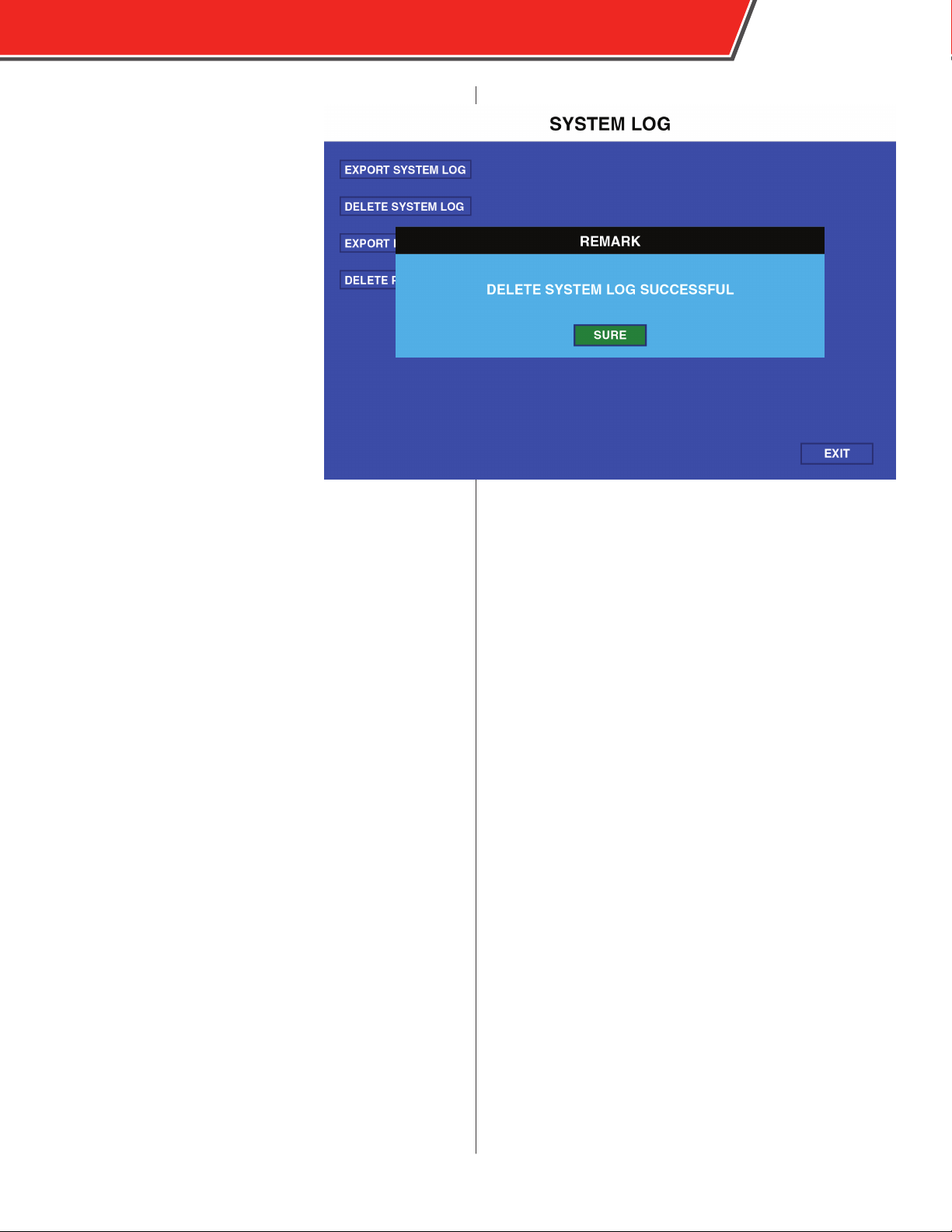
System Log
The System Log menu allows the
user log or pictures to be exported or
deleted. The system log le contains a
log of which users accessed the DVRs
conguration menus and at what time
and date.
To export the user log le:
1. Insert a USB ash drive into the
front USB port.
2. Select EXPORT SYSTEM LOG.
The system log is automatically
exported to the USB ash drive.
To delete the user log:
1. Select DELETE SYSTEM LOG.
A remark window appears.
2. Select OK/SURE.
The system log is deleted.
OBSERVER 4000 USER GUIDE
19
Pictures can be exported and deleted using the EXPORT
PICTURES and DELETE PICTURES buttons using the same
procedures as described above.
Page 22

20
Blackbox File
The Blackbox File menu downloads a
“blackbox” le to a USB drive inserted
into the DVR’s USB port. This blackbox
le contains metadata on assorted
parameters of the DVR.
1. Insert a USB ash drive into the
DVR’s USB port.
2. Select the BLACKBOX FILE op-
tion.
A prompt appears as the blackbox
le is automatically downloaded to
the USB drive.
OBSERVER 4000 USER GUIDE
Page 23
OBSERVER 4000 USER GUIDE
Record Menu
The Record Menu contains parameters that control how
video is recorded.
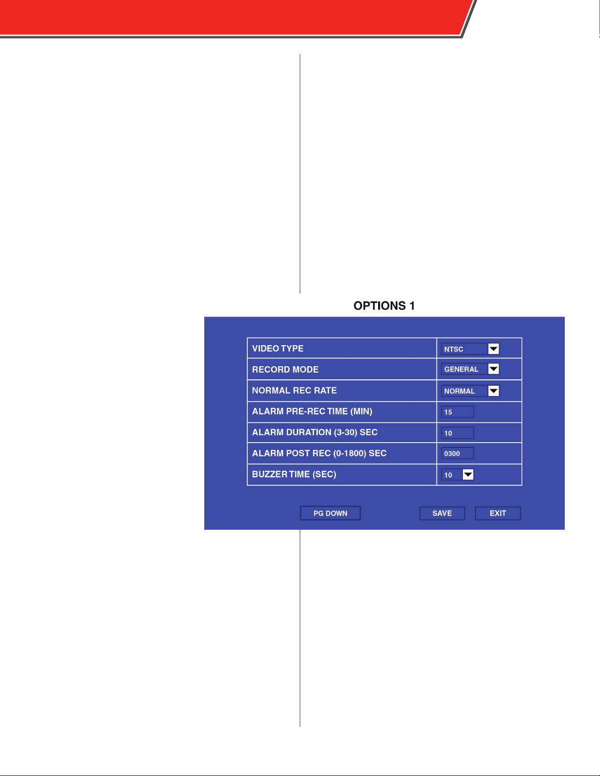
Options (Page 1)
The Options menu contains most of
the parameters that control how long
and when the DVR records video.
21
VIDEO TYPE: Select NTSC or PAL.
RECORD MODE: Select GENERAL
to began full-time recording
automatically when the DVR is
powered on. Select TIMER to begin
recording as dened in the Time
Record menu. Select EVENT to record
only when an event is triggered.
NORMAL RECORD RATE: Select
NORMAL to record video at the
quality specied in the Record Setting
menu at all times. Select 1 FRAME
to normally record only 1 frame per
second, until an event is triggered,
when recording will automatically
switch to the quality specied in the
Record Setting menu. This option is
useful to conserve storage space.
RECORD FILE TIME: Select the duration (15, 30, 45, 60
minutes) of recording packets.
ALARM DURATION: Select the amount of time, from 3 to 30
seconds, to be recorded and marked as an event.
ALARM POST REC TIME: Select the amount of time, up to
1800 seconds, to be recorded after triggering an event.
OUTPUT DUR. TIME: Select the duration of time (between
0-240 seconds) that an optional electrical output is sent
during an alarm.
If an event is trigger while another
event is being recorded it will be
considered one event. The event will
end after the second trigger and the
time specied in the ALARM DURATION
eld.
Page 24
22
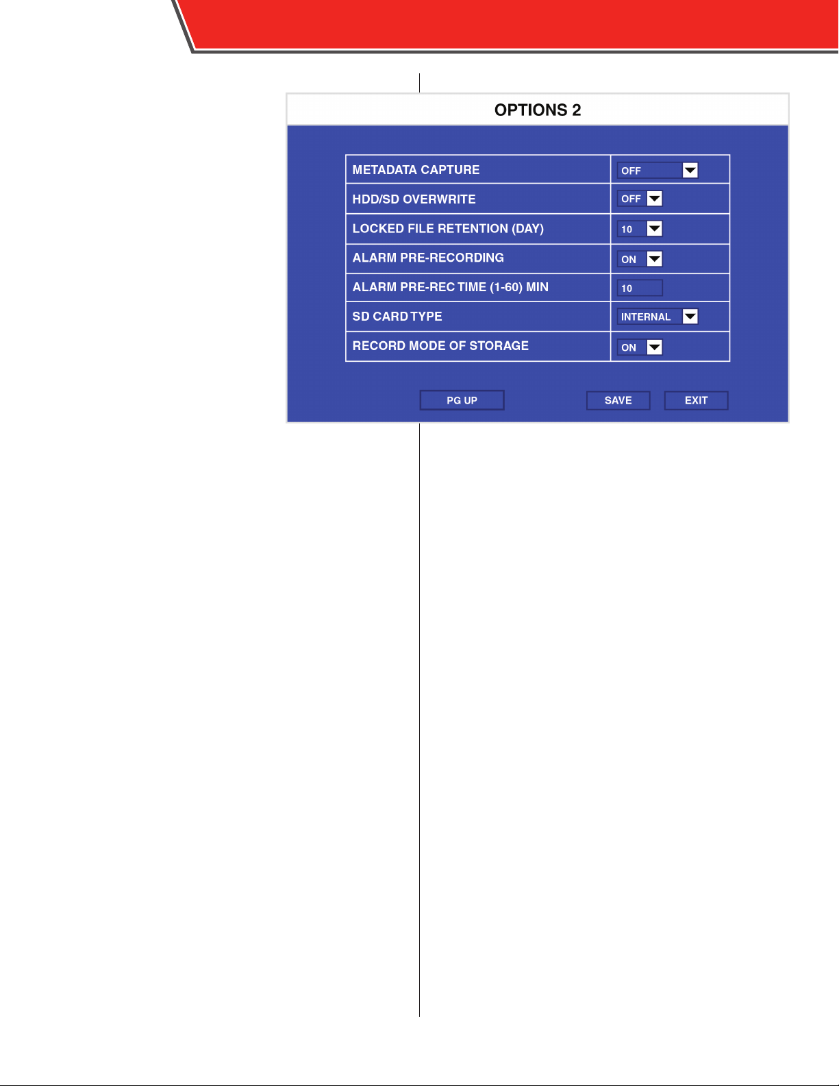
Options (Page 2)
METADATA CAP T URE: Select ON to
record meta-data with recorded video.
Select OFF to record video only.
HDD/SD OVERWRITE: Select ON to
overwrite the oldest video existent on
the storage media when storage space
is near capacity. Select OFF to stop
all recording video after the storage
media is full (necessitating manual le
deletion).
LOCKED FILE RETENTION: Select the
number of days locked les remain
locked, before they become unlocked
(and able to be overwritten). Select 7,
10, 15, 20, 30, or 45 days.
ALARM PRE-RECORDING: Select 15,
30, 45 or 60 minute le packing sizes
(optional)
ALARM PRE-REC TIME: Select 15,
30, 45 or 60 minute le packing sizes
(optional)
SD CARD TYPE: Select INTERNAL.
RECORD MODE OF STORAGE: Select from the following
options:
• OFF - Disable any recording to the secondary SD card.
• SUB - Enable mirror recording to the secondary SD card.
Data recorded to the primary SD card is duplicated on
the secondary SD card in case the primary SD card fails
• CYC REC - Enable cycle recording to the secondary
SD card. Cycle recording begins recording to the
secondary SD card when the primary SD card is full.
OBSERVER 4000 USER GUIDE
See the Event List section for more
information on locked and unlocked
les.
Options (Page 3)
VIDEO LOSS REC: Select ON to continue recording a video
channel when a video loss occurs. Select OFF to cease
recording when a video loss occurs.
Page 25
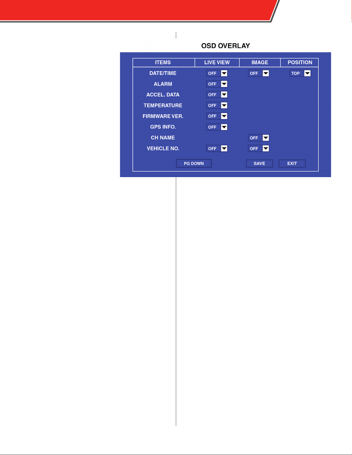
OSD Overlay
The OSD Overlay menu selects what
elements appear on the on-screen
display.
Select OFF or ON from the LIVE VIEW
column to display the associated
element when you press the Enter key
on the remote control when the DVR is
in Live View.
Select OFF or ON from the RECORD
column to make this information
available when reviewing recorded
video.
Additionally the DATE/TIME eld can
be moved to the TOP or BOTTOM of
the screen.
OBSERVER 4000 USER GUIDE
23
The following information is available to be displayed:
DATE/TIME: The date and time of the recording.
ALARM: The trigger that initiated the recording (if active)
ACCEL. DATA: This data is not available for the Observer
4000.
TEMPERATURE: The internal temperature of the DVR.
FIRMWARE VER.: The current rmware version installed on
the DVR.
GPS INFO: The direction the vehicle is traveling as
determined by the optional GPS module
CH NAME: The name of the camera displayed
VEHICLE NO.: The vehicle number as entered in the
Register Info menu
Page 26
24
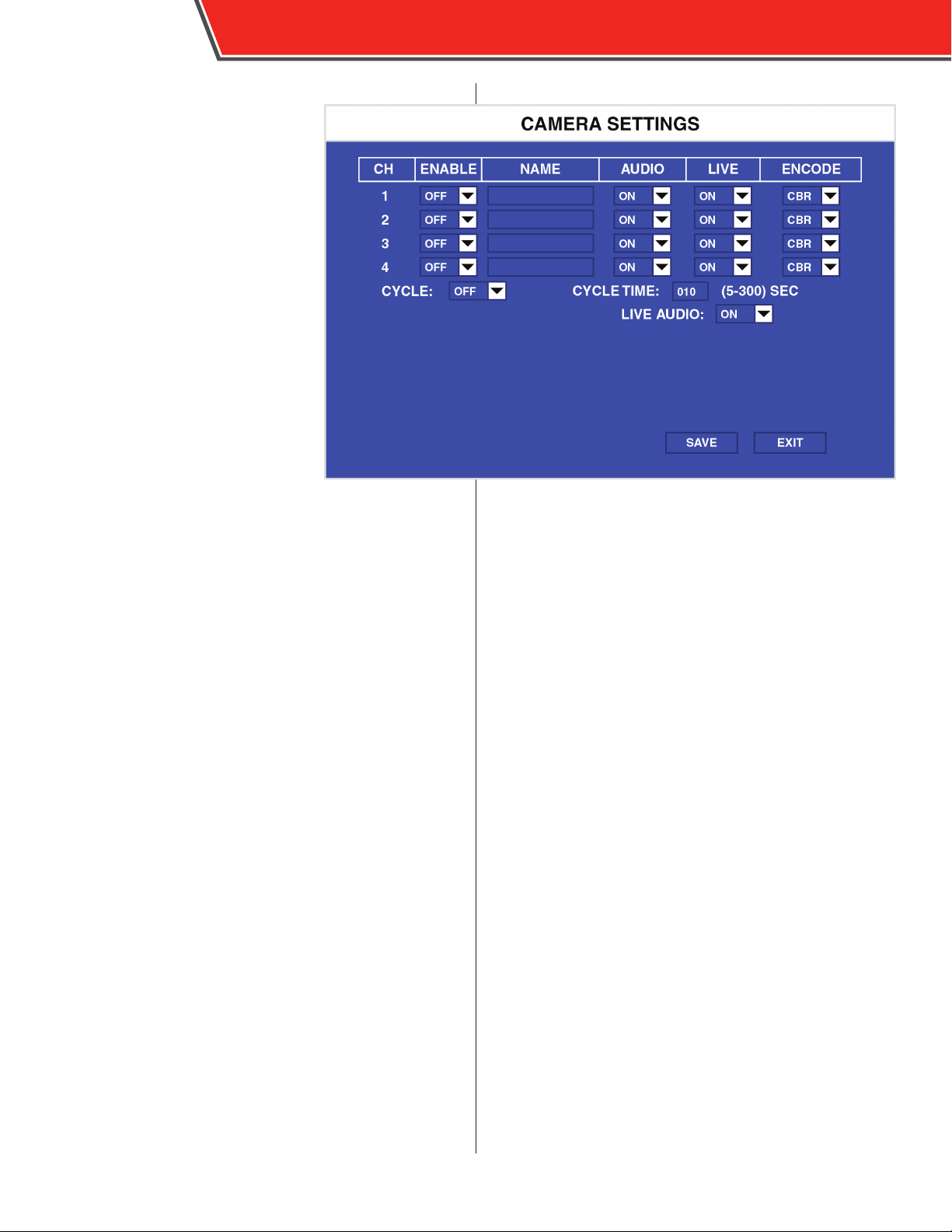
Camera Settings
The Camera Setting menu controls
which cameras are recorded and
displayed in the live view.
Select the following for each camera:
ENABLE: Select ON to enable
recording of this camera.
NAME: Enter an optional alphanumeric
name for each specic camera.
AUDIO: Select ON to enable audio
recording for this camera.
LIVE: Select ON to display this camera
in the live view.
ENCODE: Select CBR for constant bit
rate (keeps camera bit rate constant
regardless of motion, but less ecent
in using storage space) or VBR for
variable bit rate (varies bit rate
depending on motion for for ecent
storage usage).
OBSERVER 4000 USER GUIDE
CYCLE: Select ON to display the cameras in a loop (the
cameras display in succession in full screen mode).
CYCLE TIME: Enter the amount of time (between 5 and 300
seconds) to display each camera before advancing to the
next one.
LIVE AUDIO: Select ON to enable audio to play during the
Live View.
Page 27
OBSERVER 4000 USER GUIDE
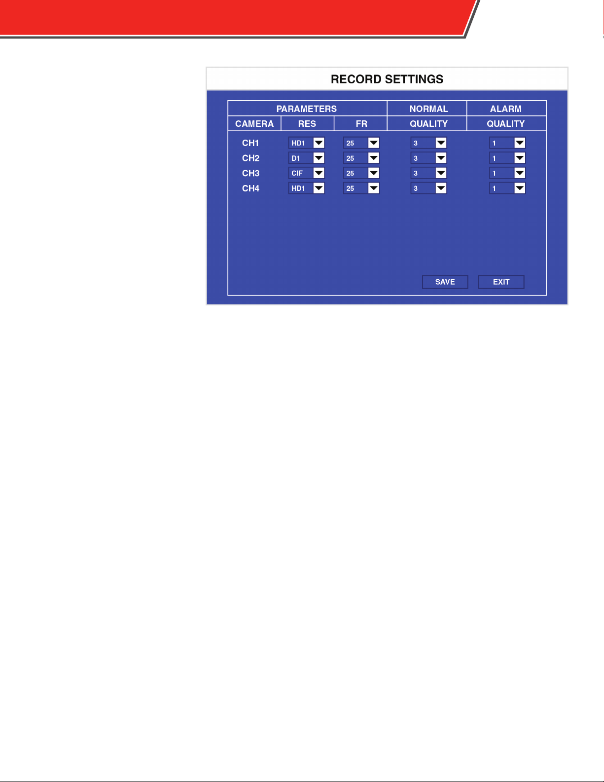
Record Settings
The Record Setting menu controls the
framerate and resolution of recorded
video. Each camera’s parameters can
be set independently.
Select the following for each channel:
RES: Select the resolution of this
camera. Select from D1 (704×576),
HD1 (704×288), or CIF (354×288).
FR: Select the frame rate in seconds of
this camera. Select from 1 to 30 FPS.
NORMAL QUALITY: Select the quality
of recording during normal recording,
with 1 being the best (for optimal
images) and 8 being the lowest (for
optimized recording time).
ALARM QUALITY: Select the quality
of recording during an event, with 1
being the best (for optimal images) and
8 being the lowest (for optimized recording time).
25
Page 28
26
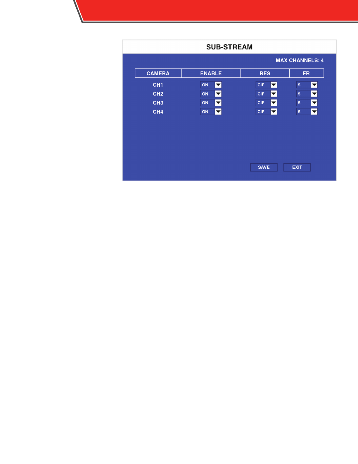
Sub-Streaming
The Sub-Streaming menu is similar to
the Record Setting menu, except it
controls the quality of a camera’s substream.
Select the following for each channel:
ENABLE: Select ON to enable this
camera for sub-streaming. Select OFF
to disable it.
RES: Select the resolution for this
camera when sub-streaming. Select
from CIF or QCIF.
FR: Select the frame rate in seconds
of this camera when sub-streaming.
Select from 1 to 30 FPS.
OBSERVER 4000 USER GUIDE
Page 29
OBSERVER 4000 USER GUIDE
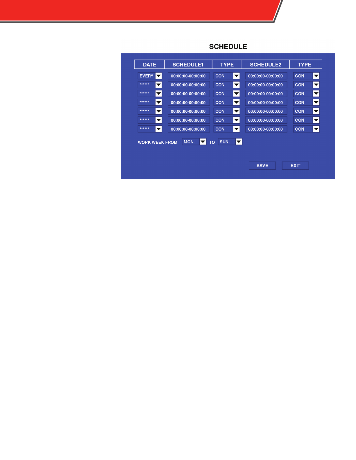
Schedule
The Schedule menu allows to the
DVR to begin and end recording
automatically based on a timed
schedule.
In the DATE column to select from
EVERY (every day), WEEKDAY (Monday
thru Friday) or individual days.
Asterisks (******) disable automatic
recording during the selected times on
that line.
SCHEDULE 1 and SCHEDULE 2 allow
two dierent recording times during
the same day, for example, if the
vehicle operates during two dierent
shifts.
Enter automatic recording times using
the number keys on the remote control
in the HH:MM:SS-HH:MM:SS format, where the rst time
is when recording will begin and the second time is when
recording will stop. All times are in the 24-hour format.
For each scheduled time, select CON (for continuous
recording) or ALARM (for event-based recording) in the
TYPE eld.
27
Scheduled recording times starting
before midnight (23:59:59 and before)
that end the next day (00:00:00 and
afterwards) continue recording without
interruption.
Select the duration of your agency-specic work week in
the WKD: WEEKDAY FROM: elds. This indicates the days
scheduled recordings occur when set to WEEKDAY.
Page 30
28
OBSERVER 4000 USER GUIDE
Event Menu
The Event Menu contains parameters that control connected
sensor inputs and how events are recorded.
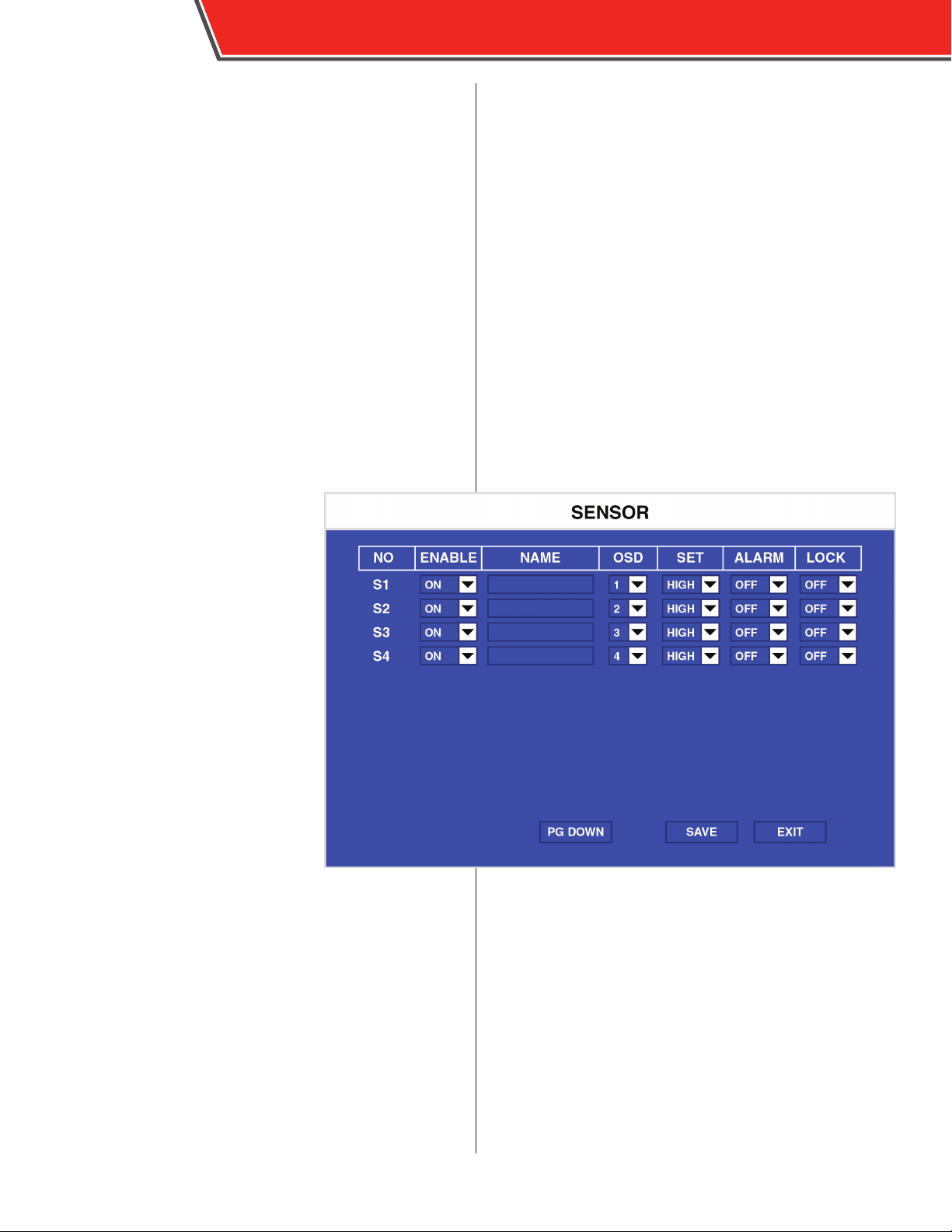
Sensor
The Sensor menu controls each sensor
input that triggers events. The DVR
supports up to eight inputs and can
congure each one individually.
Use the remote control to congure
the following for each individual input:
ENABLE: Select ON to enable this
sensor for input. Select OFF to disable
it.
NAME: Press Enter on the remote
control to display an on-screen
keyboard and enter the name for this
sensor here.
OSD: Press Enter on the remote control
to display an on-screen keyboard and
enter an abbreviated or truncated
name of the sensor here. This name
appears in the OSD while reviewing
video in Foresight SD.
SE T: Select LOW for low to high (normally closed, NC), or
select HIGH for high to low (normally open, NO).
ALARM: Select ON to enable the ALM LED on the front of the
DVR when a sensor is triggered and marks video as “R” so
that it can be automatically downloaded (see page 13). This
LED continues to ash after an event is triggered until the
conguration menus are accessed.
LOCK: Select ON to lock the video of the event recorded
when this sensor is triggered (not allowing it to be
overwritten).
A sensor must be installed and
wired properly to the DVR in order
for it to function properly. For more
information see the Installation
section.
Page 31
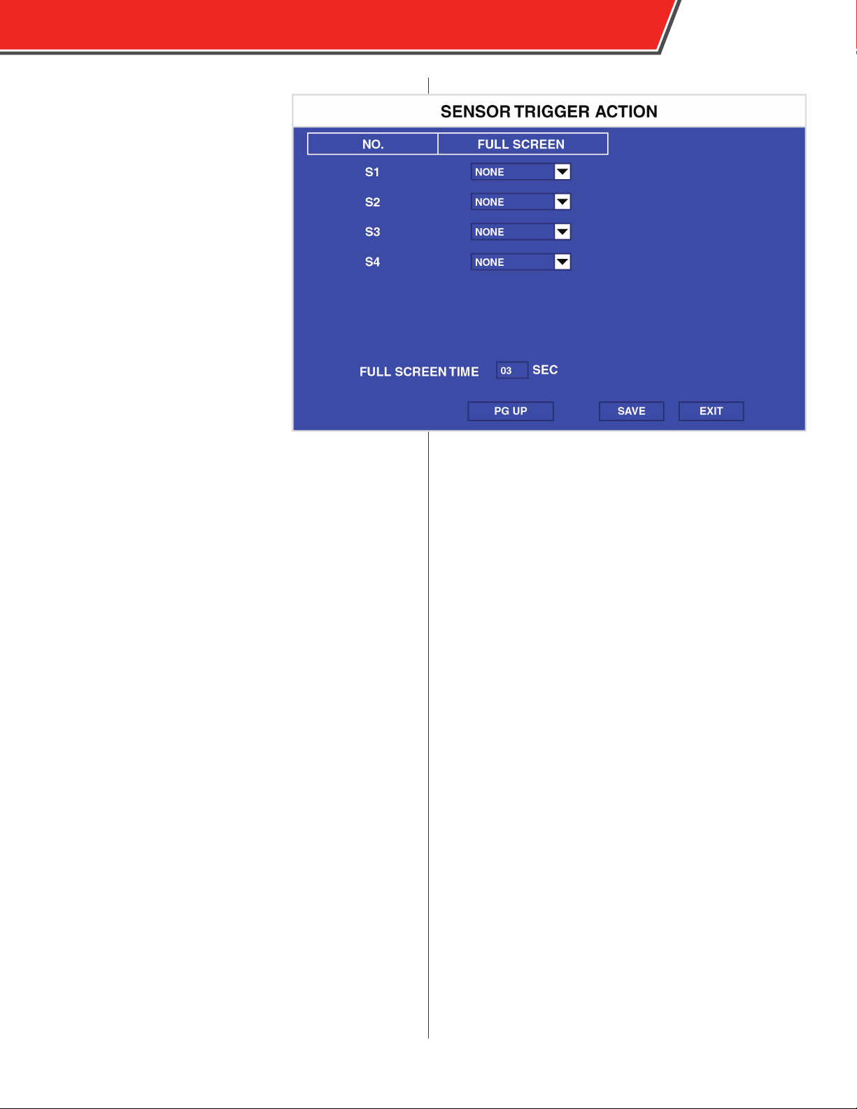
Sensor Trigger Action
Select NEX T PAGE on the Sensor
menu to access this menu.
The Sensor Trigger Action menu
allows a channel to be displayed in
fullscreen when an event is triggered.
For each sensor, select a channel to
displayed in the FULL SCREEN eld
when that sensor is active. Select an
individual camera or the “1-4” option,
which displays a quad-view. Enter the
amount of time channels are displayed
in full screen in the FULL SCREEN TIME
eld.
Lower numbered sensors override
later ones. For example, if both sensor
1 and sensor 4 are active, the camera
assigned to sensor 1 is displayed.
OBSERVER 4000 USER GUIDE
29
Page 32
30
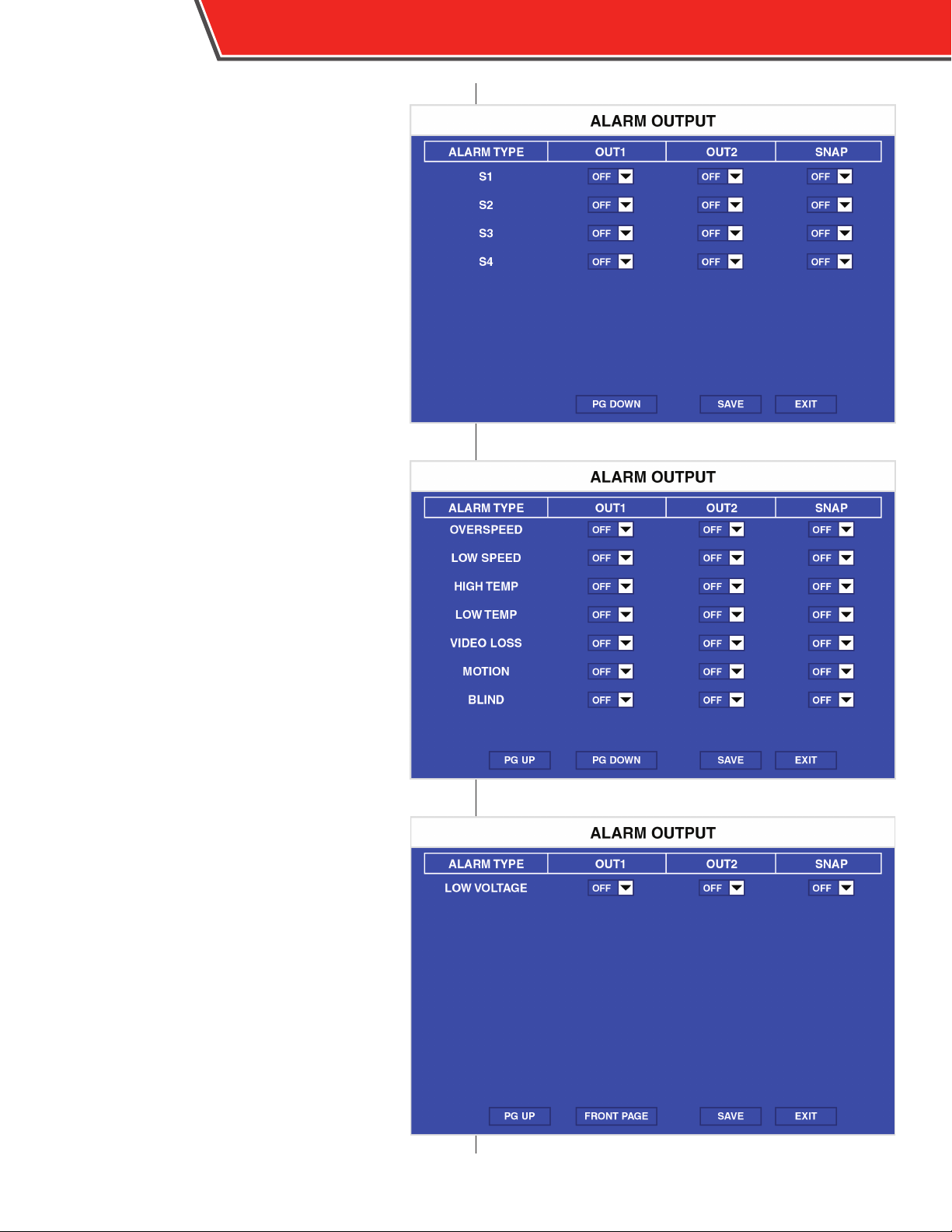
Alarm Output
The Sensor Alarm Output menus select which
outputs are active when certain alarms are
triggered.
For each alarm type, select ON or OFF for outputs
1 and 2 (OUT1 and OUT2). Select ON in the SNAP
eld for each alarm type to produce a .jpg snapshot
when that alarm is triggered.
OVERSPEED, LOW SPEED, HIGH TEMP., LOW TEMP.,
type alarms are controlled by settings in the
Speedand Temperature menus, respectively.
OBSERVER 4000 USER GUIDE
Page 33
Speed
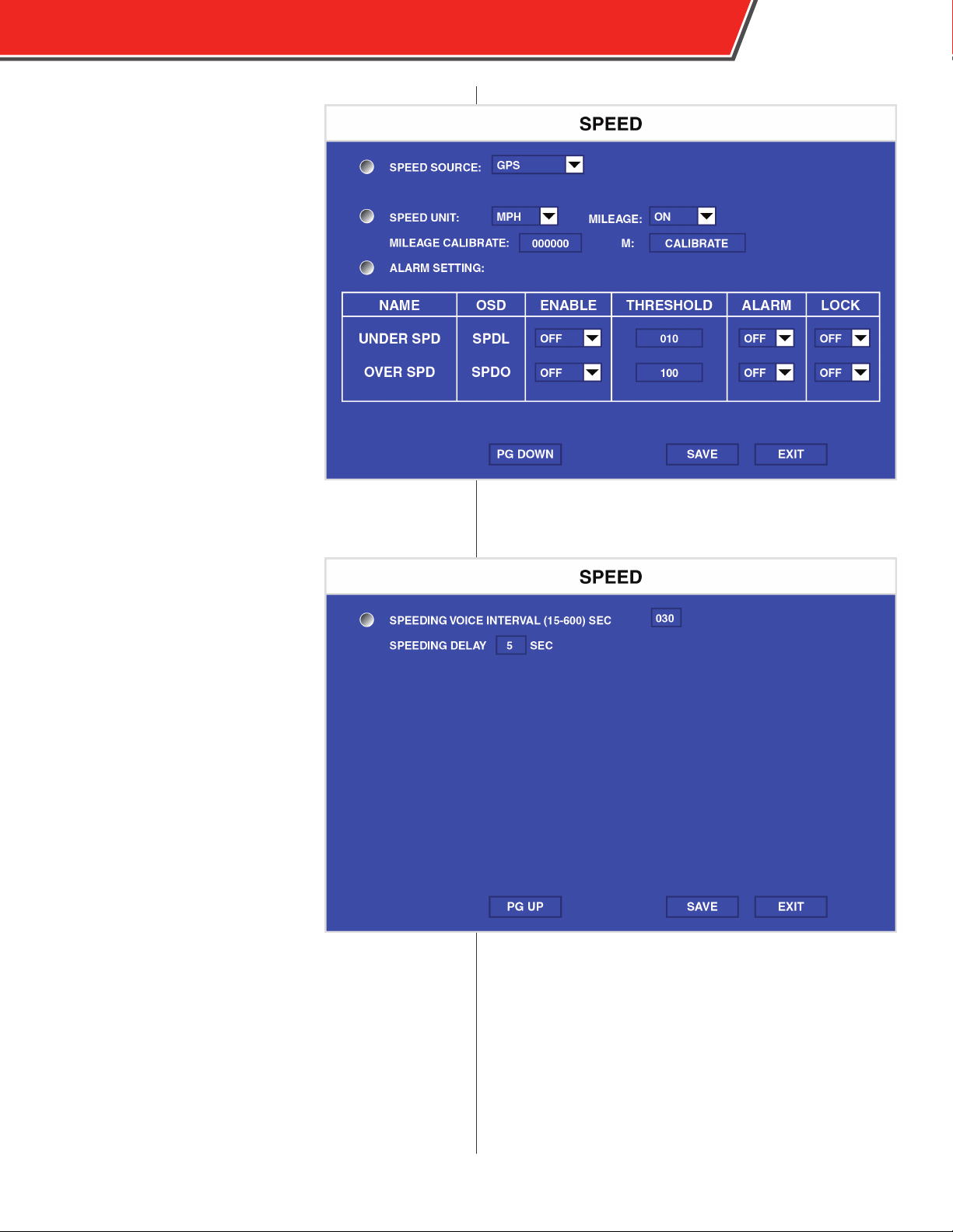
The Speed menu controls the speed
type (SPDL and SPDO) events.
Use the remote control to congure
the following options:
SPEED SOURCE: Select VEHICLE to
obtain vehicle speed data from the
vehicle’s own speedometer, or GPS to
obtain this data from the GPS signal.
For more information about connecting
the DVR to a vehicle speedometer, please
contact Safety Vision Technical Support.
SPEED UNIT: Select MPH to use miles
per hour or KPH to use kilometers per
hour.
ALARM SETTING: Select the
following options for LOWSPEED and
OVERSPEED:
OBSERVER 4000 USER GUIDE
31
ENABLE: Select ON to enable this
SPEED event. Select OFF to disable it.
THRESHOLD: Use the number keys on
the remote control to enter the speed
at which the event is triggered.
ALARM: Select ON to enable the ALM
LED on the front of the DVR when the
THRESHOLD speed is reached and an
event is triggered. This LED continues
to ash after an event is triggered until
the conguration menus are accessed.
LOCK: Select ON to lock the video
of the recorded event when the
THRESHOLD speed is reached (not
allowing it to be overwritten).
Speed (Page 2)
SPEEDING VOICE INTERVAL: Enter the
amount of time (between 15 and 600
seconds) between which an optional
voice notication is sounded when a
Speed type alarm occurs.
SPEEDING DELAY: Enter the amount of time, in seconds,
between when the entered speed is exceeded and an alarm
actually occurs.
Page 34
32
Camera
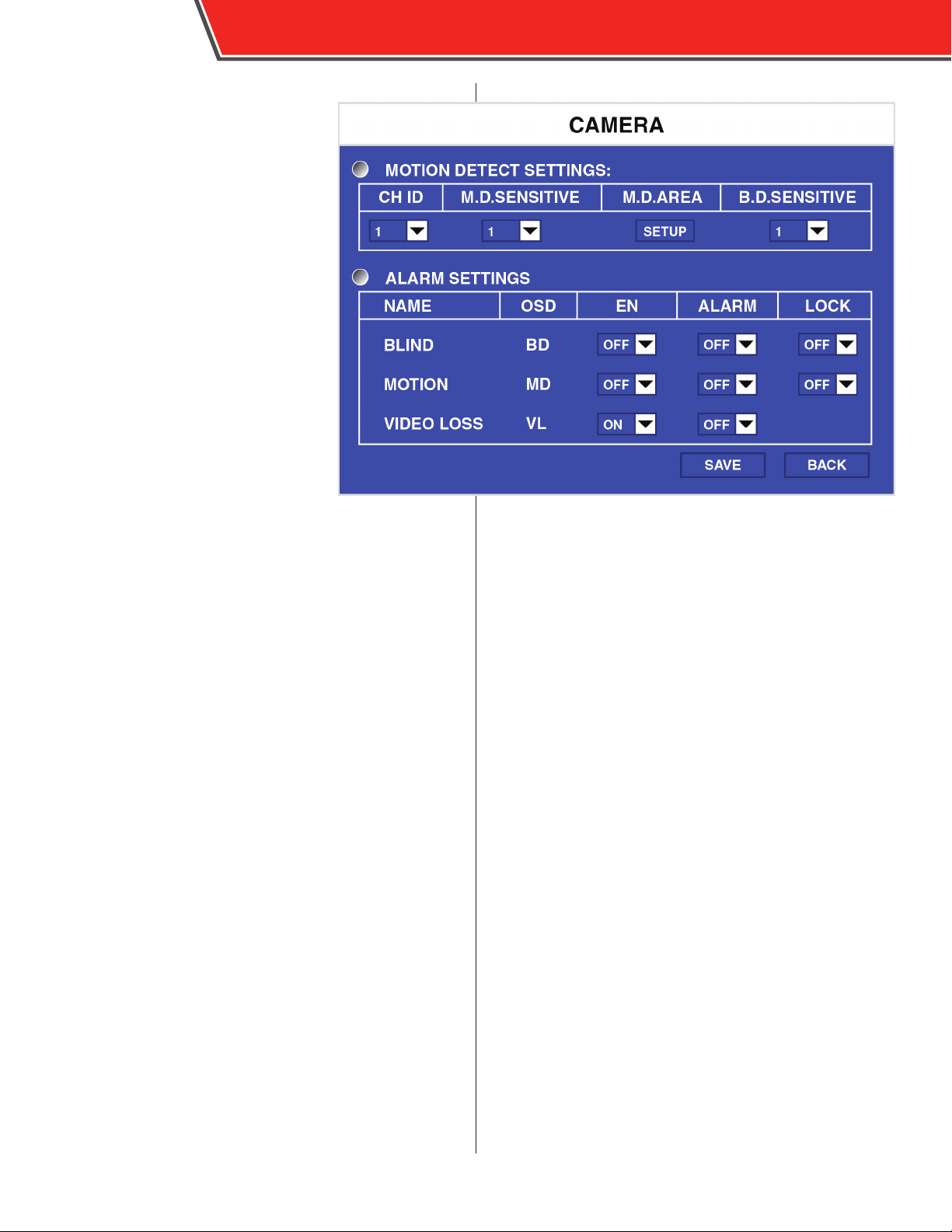
The Camera menu controls camera
motion detection settings and
associated events.
Use the remote control to congure the
following options:
MOTION DETECT SETTINGS
CH ID: Select the channel to congure
the following settings.
M.D. SENSITIVE: Select the sensitivity
of the motion detection feature, with
3 being the most sensitive. The more
sensitive the motion detection, the
smaller the movements can be that
trigger events.
M.D.AREA: Select Setup to enter the
motion detection setup screen. Use
the cross keys on the remote control
to shade in red the area of view that is
monitored for motion. Use the Enter key to switch between
shading and not shading. This is useful when the camera’s
angle of view covers both areas with frequent motion and
monitored areas.
B.D.SENSITIVE: The blind detection feature senses when
a camera’s view may be purposely blocked. Select the
sensitivity of the blind detection feature, with 3 being the
most sensitive. The more sensitive the blind detection, the
smaller the movements can be that trigger events.
OBSERVER 4000 USER GUIDE
ALARM SETTINGS
For each type of alarm (BLIND, MOTION, and VIDEO LOSS),
select ON or OFF for the following:
EN: Select ON to enable the event. Select OFF to disable it.
ALARM: Select ON to enable the ALM LED on the front of the
DVR when the event is triggered. This LED continues to ash
after an event is triggered until the conguration menus are
accessed.
LOCK: Select ON to lock the video of the recorded event.
Page 35
Low Voltage Protection
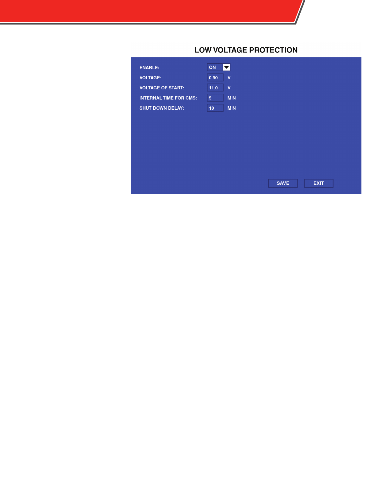
The Low Voltage Protection menu
controls the voltage threshold before
the DVR shuts down automatically to
protect itself.
Use the remote control to congure
the following:
ENABLE: Select ON to enable voltage
protection.
LOW VOLTAG E : Enter the minimum
voltage, in volts, that the DVR can
receive before it automatically
disconnects from the CMS or shuts
down.
VOLTAG E OF START: Enter the voltage,
in volts, that the vehicle typically
drops to during startup (the ignition
key is turned).
INTERNAL TIME FOR CMS: This option
is not supported by the Observer 4000.
OBSERVER 4000 USER GUIDE
33
Page 36
34
Snap Settings
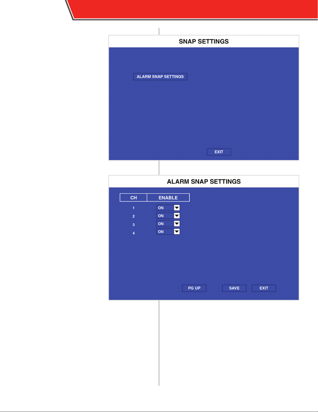
The Snap Settings menu enables
snapshot mode for each camera.
When snapshot mode is enabled,
video is recorded in a series of snap
shots taken in a constant interval. This
may reduce storage usage for some
non-critical camera views.
For each camera, select ON to enable
snapshot mode.
OBSERVER 4000 USER GUIDE
Page 37
OBSERVER 4000 USER GUIDE
Fatigue Driving
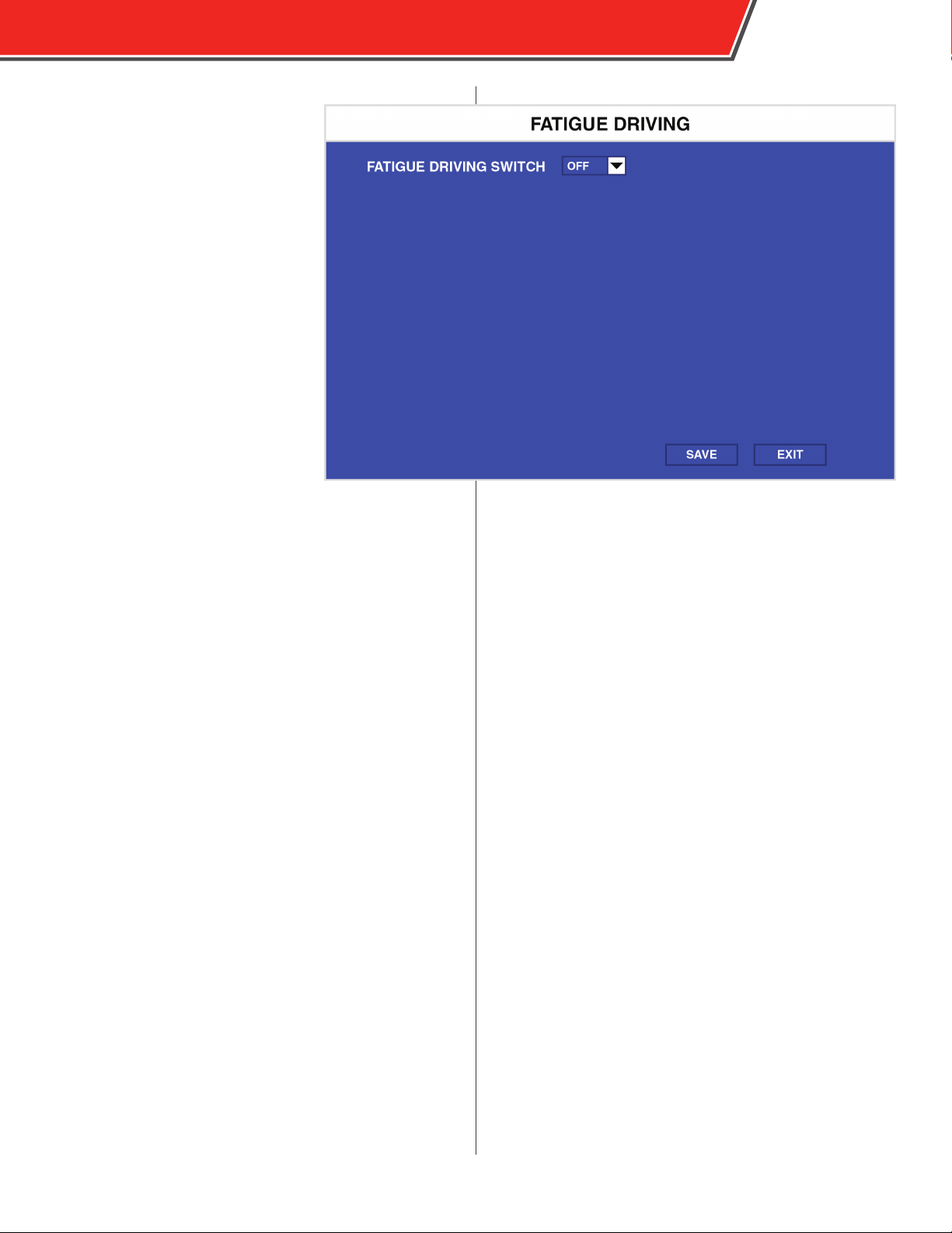
The Fatigue Driving menu congures
an available alarm parameter that
denes how long a vehicle operator is
authorized to drive and how long he
must rest.
First select ON in the FAT I GUE
DRIVING SWITCH eld to activate the
feature.
Enter the time the operator is
authorized to drive continuously
before resting in the DRIVING
DURATION eld in HH:MM:SS format.
When a driver exceeds this time
(based on the DVR being powered on
continuously), an alarm is recorded.
Enter the time a driver must rest
between turning the vehicle (and DVR)
o before resuming operation in the REST DURATION eld
in HH:MM:SS format.
35
Page 38
36
OBSERVER 4000 USER GUIDE
Peripheral Menu
The Peripheral Menu contains parameters that control
optional connected peripheral accessories.
Ext. Com. Setup
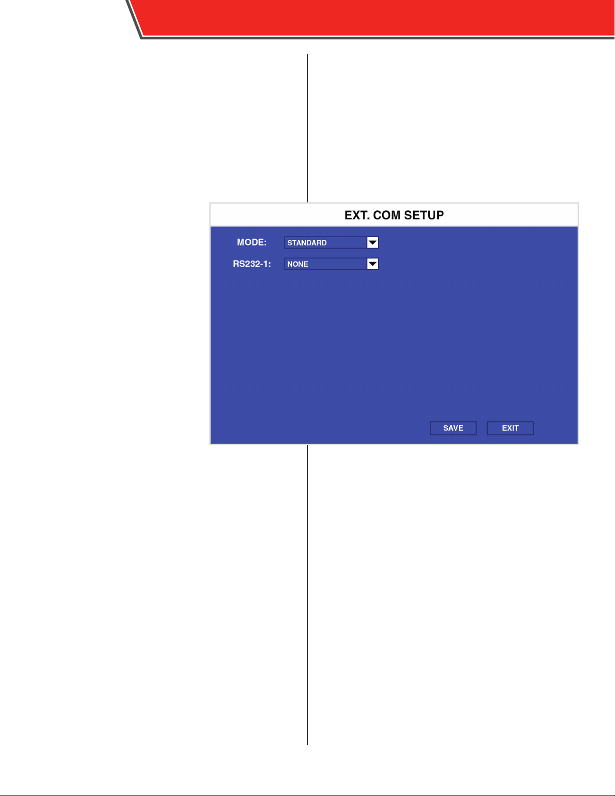
The Ext. Com. Setup menu enables
optional connections to the RS232
port.
MODE: Select STANDARD.
RS2 32-1: Select NONE or EXT GPS for
the optional Garmin GPS antenna.
Page 39
Language Switch
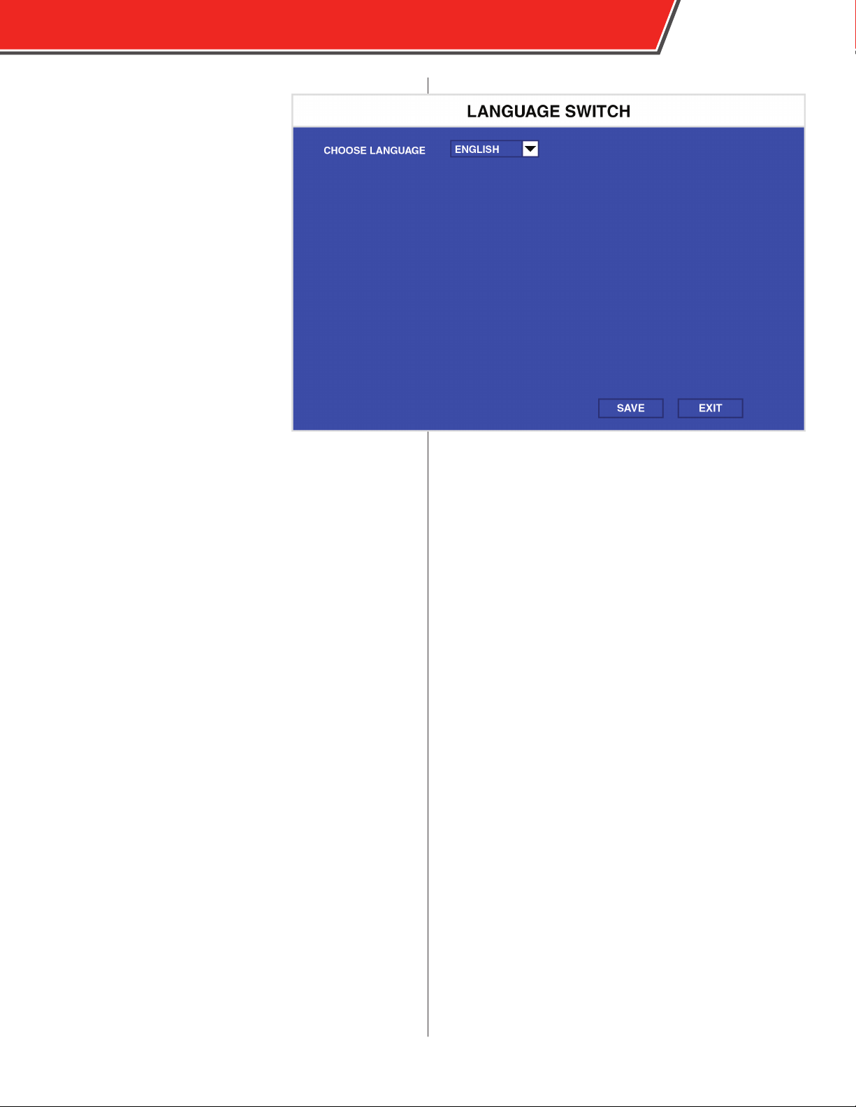
The Language Switch menu allows you
to change the language of the DVR’s
conguration menus.
In the CHOOSE LANGUAGE eld,
select English, Russian, Spanish, Polish,
Portugese, or Turkish.
OBSERVER 4000 USER GUIDE
37
Page 40
38
OBSERVER 4000 USER GUIDE
System Information
Select the System Information icon to display the System,
History, Modules, and Authorized menus.
These menu options display unique information and history
about the DVR unit.
System
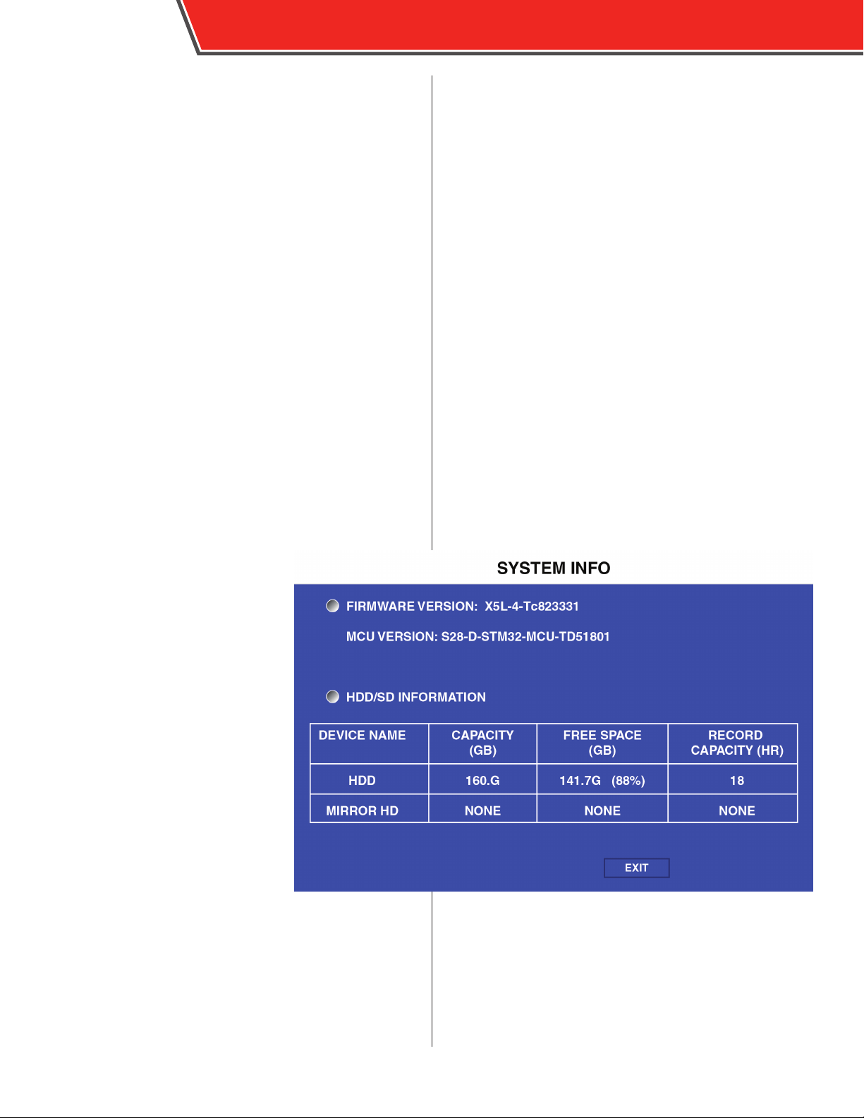
The System menu displays the rmware version and information on the
SD card.
FIRMWARE VERSION: The version of
rmware currently installed.
MCU VERSION: The MCU feature is not
active at this time.
DEVICE NAME: Displays the name of
the storage unit.
CAPACITY: Displays the overall capacity of the storage unit, in gigabytes
(GB).
FREE SPACE: Displays the remaining
storage capacity of the storage unit, in
gigabytes (GB).
RECORD CAPACITY: Displays the overall recording capacity of the storage
device (in hours), based on the capacity
and setting made in the conguration menus.
If information about a storage device
is displayed in this menu, it is operating
as normal.
Page 41
OBSERVER 4000 USER GUIDE
History Info
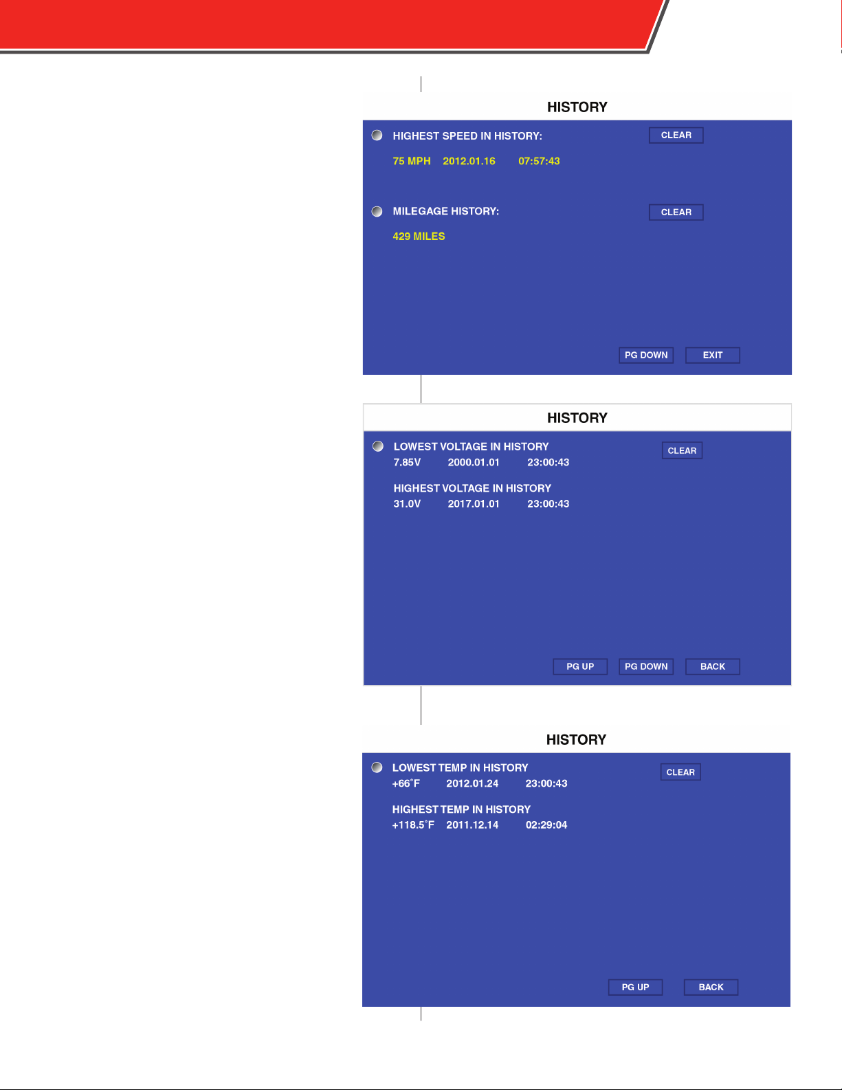
The History Info menu consists of three pages.
Select CLEAR next to any record to reset it.
HIGHEST SPEED IN HISTORY: Displays the highest
obtained speed, including the date and time it was
recorded (assuming speed data is collected).
MILEAGE HISTORY: Displays the total amount of
miles (or kilometers) driven.
LOWEST VOLTAGE IN HISTORY: Displays the lowest
received voltage, including the date and time it was
recorded.
HIGHEST VOLTAGE IN HISTORY: Displays the
highest received voltage, including the date and
time it was recorded.
39
LOWEST TEMP IN HISTORY: Displays the lowest
internal temperature, including the date and time it
was recorded.
HIGHEST TEMP IN HISTORY: Displays the highest
internal temperature, including the date and time it
was recorded.
Page 42

40
Module Status
The Modules menu displays the status
of optional installed modules.
GPS MODULE: Displays NORMAL if a
GPS module is installed; NONE is one
is not.
GPS SIGNAL: Displays if the GPS signal
received is valid.
OBSERVER 4000 USER GUIDE
Page 43

OBSERVER 4000 USER GUIDE
Appendix A: Specications
SPECIFICATIONS
Operating System
Video Standard
Audio/Video Inputs
Audio/Video Output
Audio/Video Compression
Resolution*
Frame Rate*
Image Qualit y (Bit Rate)
Recording Mod e
Pre-Event Recording
Post-Event Recording
Mirror Recording
GPS (Antenna Included)
Storage (lockable) 1 × Class 10 SD Card (128GB max)
Interfaces
Sensor Inputs
Power Input
Power Output
Power Consumption
Dimensions (w x h x d)
Weight
Operating Temperature
Relative Humidity
Certicates
Conguration
WITH A SAFETY VISION MONITOR
On Screen Dis play
Display Split
Playback
Search Mode
Embedded Real Time Linux 2.6.24
NTSC / PAL selectable
4 channels
1 channel
ADPCM / H.264
D1, HD1, CIF
100FPS global NTSC / 120FPS global PAL
8 levels (1 is best)
Continuous (dual stream) / scheduled / event (sensor trigger, speed, acceleration,
video loss, temperature), pre/post recording
Congurable up to 60 minutes
Congurable up to 30 minutes
Yes
Built-in module (location tracking, speed detection, and time sync)
1 × Class 10 SD Card (128GB max, mirror recording)
1 x RS-232 and 1 x USB 2.0 (on front panel; lockable)
4 inputs, 2 outputs
8 - 36V DC
12V at 500mA
13.5V at 1.2A, 27V at 0.5A
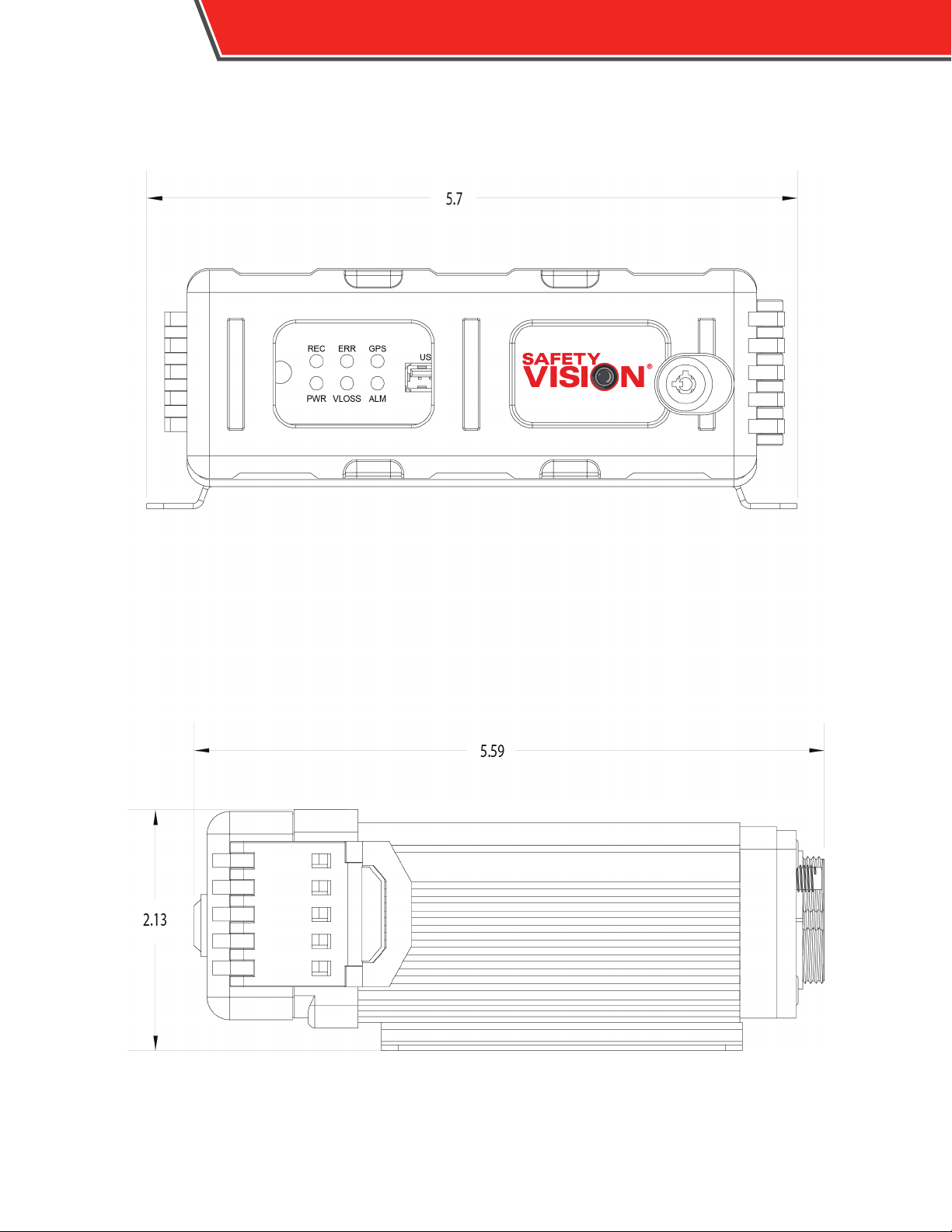
5.59in. x 2.13in. x 5.7 in. (142mm x 54.2mm x 144.8mm)
1.5 lbs. (0.7 kg.)
-13°F~140° F (-25°C~60 ° C )
8% - 90%
CE, FCC, MIL-STD-810F
IR remote control (included); monitor (optional)
GPS information, event, temperature, voltage, device information, rmware version,
MCU version
1/4
1 chan. by local monitor, 1/4 chan. with software
Date/time, channel, event
41
*congurable per channel and event
Page 44
42
OBSERVER 4000 USER GUIDE
Appendix B: Dimensions
Page 45

OBSERVER 4000 USER GUIDE
43
[this page intentionally left blank]
Page 46

44
Limited 3-Year New Product Warranty
Safety Vision, LLC (“SV”) makes the following limited warranty, which is eective at
the time of the original end-user purchase.
Note: Optional warranty products are available for all SV products and may be purchased at the time of the original end-user purchase or any time during the original
Limited 3-Year New Product Warranty period.
SV warrants this product against defects in materials for a period of 3 years after the
date of purchase. During this period, SV will repair or replace a defective product or
part without charge to the customer. The customer must send the defective product
or part to SV or an authorized SV dealer. The customer must pay for all transportation and insurance charges for sending the unit to be repaired. SV’s total liability is
limited to the original product cost.
User Guide
The customer should thoroughly read this guide before operating this product.
Customer’s Responsibility
The above warranty is subject to the following conditions:
OBSERVER 4000 USER GUIDE
• Customer must notify SV within 10 days of discovering the defective product or
part and provide a description of the defect and complete information about
the manner of its discovery.
• All warranty servicing of this product must be performed by SV or an authorized
servicing agent.
• Warranty extends only to defects in materials as limited above. Warranty
does not extend to any product or part that has been lost or discarded by
the customer; to damage to products or parts caused by misuse, accident,
improper installation, improper maintenance, or use in violation of instructions
furnished with the product; to units that have been altered or modied without
authorization of SV; to damage to products or parts thereof that have had
the serial number removed, altered, defaced, or rendered illegible; or to any
failure of the product to function caused by burglary, re, ood, war, riot, civil
commotion, Acts of God, or any other condition beyond the control of SV.
Obtaining Warranty Service
To obtain warranty service, the customer must contact the SV Service and Warranty Manager at 713.896.6600 or 800.880.8855 to report a defective product. (The
customer must report the model number and serial number if available.) The Service
and Warranty Manager will assist in troubleshooting the problem and, if necessary,
issue a return material authorization (RMA) number. The customer must include this
number on the outside of each package shipped to SV.
Important Packing and Shipping Instructions
When a product requires service, only the aected component must be returned. If
returning the RouteRecorder 4C SD SS unit, please include the SD card that was in
use at the time the issue occured. The customer must use proper packing material to ensure against damage during shipping. Any shipping damage caused by
improper packing is not covered under this warranty. In addition, the customer must
include a return material authorization (RMA) number on the outside of each package shipped to SV and a letter explaining the defect with the product.
Page 47

OBSERVER 4000 USER GUIDE
FCC Compliance Statement
NOTE
This device has been tested and found to comply with the
limits for a Class A digital device, pursuant to part 15 of the
FCC Rules. These limits are designed to provide reasonable
protection against harmful interference when the equipment
is operated in a commercial environment. This equipment
generates, uses, and can radiate radio frequency energy and,
if not installed and used in accordance with the instruction
manual, may cause harmful interference in which case the
user will be required to correct the interference at his own
expense.
CAUTION
Any changes or modications in construction of this device
which are not expressly approved by the party responsible
for the compliance could void the user’s authority to operate
the equipment.
45
Page 48

CORPORATE HEADQUARTERS
6100 W. Sam Houston Pkwy. N.
Houston, TX 77041-5113
Main: 713.896.6600
Toll Free: 800.880.8855
Fax: 713.896.6640
www.safetyvision.com
Copyri ght © 2015 Safet y Vision, LLC Al l Rights Re served.
 Loading...