

Safety 1st HS129, HS131, HS132, HS133, HS130 User Manual
3
SCREW HOLES
FOR LOCK
1A
PEEL OFF
HS025
ProGrade
HS132
Core
©2013 Cosco Management, Inc. All Rights Reserved. Todos derechos reservados.
3
SCREW HOLES
FOR LOCK
1A
PEEL OFF
www.djgusa.com (800) 544-1108 www.safety1st.com Made in CHINA. Hecho en CHINA.
Styles and colors may vary. Los estilos y los colores pueden variar.
Distributed by (distribuido por) Dorel Juvenile Group, Inc., 2525 State St., Columbus, IN 47201-7494
Dorel Distribution Canada, 873 Hodge, St. Laurent, QC H4N 2B1
09/13/13 4358-5306B
Complete Magnetic Locking System HS129, HS130, HS131, HS132, HS133
User Guide
WARNING:
• ADULT INSTALLATION REQUIRED. KEEP SMALL PARTS AWAY FROM CHILDREN DURING INSTALLATION.
• Keep magnetic key out of reach of children.
• This product contains magnets. Swallowed magnets can stick together across intestines, causing serious infections
and death. Seek immediate medical attention if magnets are swallowed.
• Do not use this product to guard against toxic and dangerous substances or sharp-edged or pointed objects. Such
materials should always be placed “high-up” or otherwise made completely inaccessible to children.
CAUTION:
• This product is only a deterrent. It is not a substitute for proper adult supervision. DO NOT use this product if damaged or broken.
• FOR INDOOR HOME USE ONLY.
BEFORE YOU BEGIN:
Important Safety Information
Check for security after installation by tugging firmly on the door or
drawer. If the latch does not securely hold the door or drawer when
tugged, adjust the latch to obtain a secure connection.
Your child will eventually be able to defeat this product. To keep this
product effective for as long as possible, avoid letting children see
how you operate child safety devices. Watching you disengage a lock,
latch or cover could enable them to learn sooner how to defeat it.
• Read all instructions before installing.
• Keep these instructions for future use.
• Remove all contents from packaging and discard box, and/or poly bags.
• Do not return this product to the place of purchase. If any parts are
missing, email consumer@djgusa.com, call Consumer Relations at (800)
544-1108, or fax at (800) 207-8182. You can also visit our website at www.
safety1st.com. Have the model number ready (HS129, HS130, HS131, HS132,
HS133) and date code (manufacture date) located on product.
• Tools needed: Hand drill or power drill, 7/64” drill bit, Phillips head
screwdriver & pencil (not provided).
• Door/drawer geometry may prohibit use.
• Avoid close proximity to metal hardware or metal objects stored in
cabinets when planning product placement, as they might make it difficult
to operate the magnetic key properly.
• Remove adhesive bumper pads on your cabinet doors only if they interfere
with installation or operation of these locks.
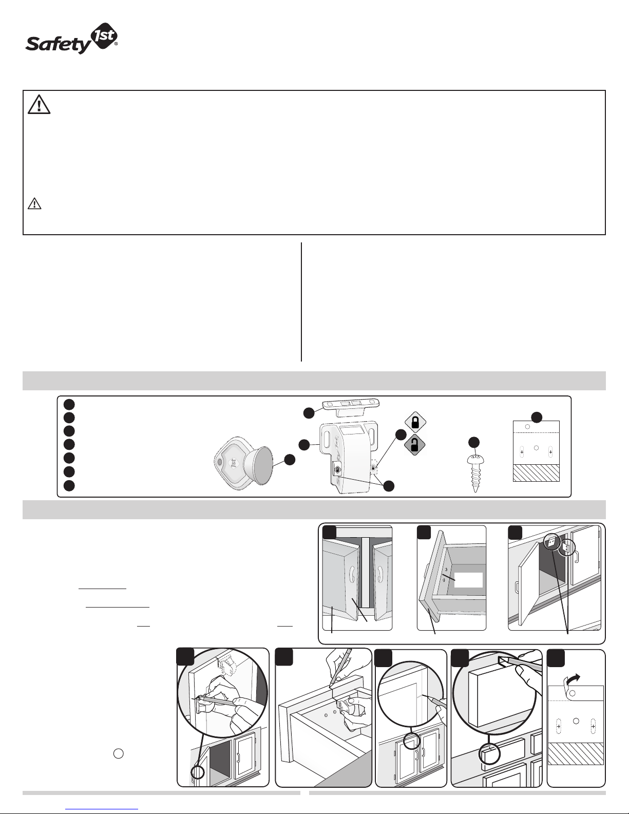
Parts & Features
Catch
A
Lock
B
Lock/Unlock button
C
SecureTechTM lock indicator
D
Magnetic key
E
Screws (4 per lock)
F
Installation template (1 per lock)
G
Determine Lock Placement
Cabinet Door and Drawer Types
There are many sizes, shapes and kinds of cabinet doors and drawer
fronts. To determine if our lock will work on your door/drawer follow
steps 1-8 below.
NOTE:
•
Doors with inset panels (Image A) may not have wide enough flat
surface.
• Drawers with outer face panels
to install this lock
•
When locks don’t fit at the top of the cabinet, they may fit at the side
(Image C).
.
1 Open door/drawer and choose a
possible location to install the lock.
Mark how far down the side of the
door/drawer or how far over on the
top of the door/drawer the lock will
be located
2 Close cabinet door/drawer and
mark your lock position on the
cabinet base
3
Peel paper (labeled 1A) off
template (Figure 3).
(Figures 1a and 1b)
(Figures 2a and 2b)
(Image B)
1a
.
.
may not have enough room
1b
A
B
E
D
Green = Locked
Red = Unlocked
F
G
1A
PEEL OFF
SCREW HOLES
FOR LOCK
3
C
A
Panel frame
Inset frame
2a
B
Inside
panel
Drawer with outer face panel
2b
C
Top or side
3
1
Determine Lock Placement
1B
PEEL OFF
2
SCREW HOLES
FOR CATCH
FOLD
3
SCREW HOLES
FOR LOCK
3
SCREW HOLES
FOR LOCK
1A
PEEL OFF
1B
PEEL OFF
2
SCREW HOLES
FOR CATCH
FOLD
2
SCREW HOLES
FOR CATCH
1B
PEEL OFF
FOLD
2
SCREW HOLES
FOR CATCH
1B
PEEL OFF
FOLD
3
SCREW HOLES
FOR LOCK
(continued)
4a Cabinets— Open door and line up template top or side edge with
pencil mark from step 2. Press down firmly to stick adhesive
(Figure 4a).
4b Drawers— Open drawer and line up template side edge with pencil
mark from step 2. Press down firmly to stick adhesive (Figure 4b).
5
Fold template inward at dotted line and use a pencil to poke
through and mark two drill locations for catch (Figures 4a and 4b).
6
Peel paper (labeled 1B) off template, then close door/drawer (Figure
5). Template will transfer from cabinet base to door/drawer (Figure
6).
If adhesive does not stick, remove bumpers from door or
drawer front.
TIP: You may be able to open adjacent door and ensure template
transfers.
Drawers— If you have an inside panel (see page 1 Image B) on
your drawer front, the bottom of the template must be flat along
the outer panel as shown in Figure 7, or the dotted slots on the
template must be fully on the inner panel as shown in Figure 7.
If template does not fit either of these two recommended options, this
lock should not be used on your drawers.
7
NOTE: If lock is being mounted on a cabinet door with an inset
panel only the part of the template with the diagonal lines should
be overhanging the recess area of the inset panel. If any more of
the template hangs over the recess of the inset panel installation in
this location is not recommended.
Use a pencil to poke through and mark two drill locations for lock
(Figure 6).
Remove template.
8 Visually inspect marked hole locations of the lock to make sure holes
are both the same distance from edge of door/drawers.
4a
5
4b
6
To Install
CAUTION: DO NOT DRILL THROUGH CABINET DOOR! DO NOT DRILL
THROUGH THIN INSET PANELS. Follow the drill manufacturer’s instructions
when using your drill. Power tools are not recommended for screw
installation.
9 Using a 7/64” drill bit predrill 3/8” deep holes at marked locations.
10 Position catch with flat side facing out as shown
and use Phillips head screwdriver to install two screws. Position lock
as shown and use Phillips head screwdriver to install two screws
(Figure 7).
(Figure 7 inset)
11 Test the lock. Set lock to the locked position by pushing the lock/unlock
button so the green locking indicator is visible. Close door/drawer. Place
magnetic key over area where lock is installed and open cabinet door/
drawer to ensure it can open and close easily with no interference.
To Use
TO SET LOCK: Press lock/unlock button
locking indicator position is visible. Close door/drawer to engage
lock. Pull on door/drawer to ensure it is locked. Door/drawer is
now set in the locked position.
TO OPEN: Place the magnetic key over the area where the lock
is installed
the lock disengages. Open door. Close door/drawer to re-engage
lock.
(Figure 9).
(Figure 8)
You should hear an audible “click” when
so the green
TO DEACTIVATE FOR PERIODS OF NON-USE: Press button to
the red, unlocked position.
To Remove
To remove the lock, remove screws.
7
8
OK
OK
OK
7b7a
9
To Clean
Wipe clean. Keep lock dry.
Green = Locked
Red = Unlocked
2
 Loading...