

Safety 1st HS012 User Manual
©2010 Dorel Juvenile Group. All Rights Reserved. Todos derechos reservados.
www.djgusa.com (800) 544-1108 www.safety1st.com Made in CHINA. Hecho en CHINA.
Styles and colors may vary. Los estilos y los colores pueden variar.
Distributed by (distribuido por) Dorel Juvenile Group, Inc., 2525 State St., Columbus, IN 47201-7494
Dorel Distribution Canada, 873 Hodge, St. Laurent, QC H4N 2B1
07/08/10 4358-5322
Sliding Door Child Lock
HS012
User Guide
WARNING:
• ADULT ASSEMBLY REQUIRED. KEEP SMALL PARTS AWAY FROM CHILDREN DURING ASSEMBLY.
• In the event of an emergency, push forcefully on door to override the child lock. Overriding lock may damage it.
CAUTION:
• This product is not a toy. Do not allow children to play with it. When not in use, keep out of reach of children.
• This product is only a deterrent. It is not a substitute for proper adult supervision. Discontinue use when child becomes old enough to
defeat it.
BEFORE YOU BEGIN:
• Read all instructions before installing.
• Keep these instructions for future use.
• Remove all contents from packaging and discard box, and/or poly bags.
• Do not return this product to the place of purchase. If any parts are missing, email consumer@djgusa.com, call Consumer Relations at (800) 544-1108,
or fax at (800) 207-8182. You can also visit our website at www.safety1st.com. Have the model number ready (HS012) and date code (manufacture
date) located on located on product.
• Tools needed: Hand drill or power drill, 3/32” drill bit, Phillips head screwdriver, scissors & pencil (not provided).
• Avoid letting children see how you operate child safety devices. Watching you disengage a lock or latch could enable them to learn sooner how to
defeat it.
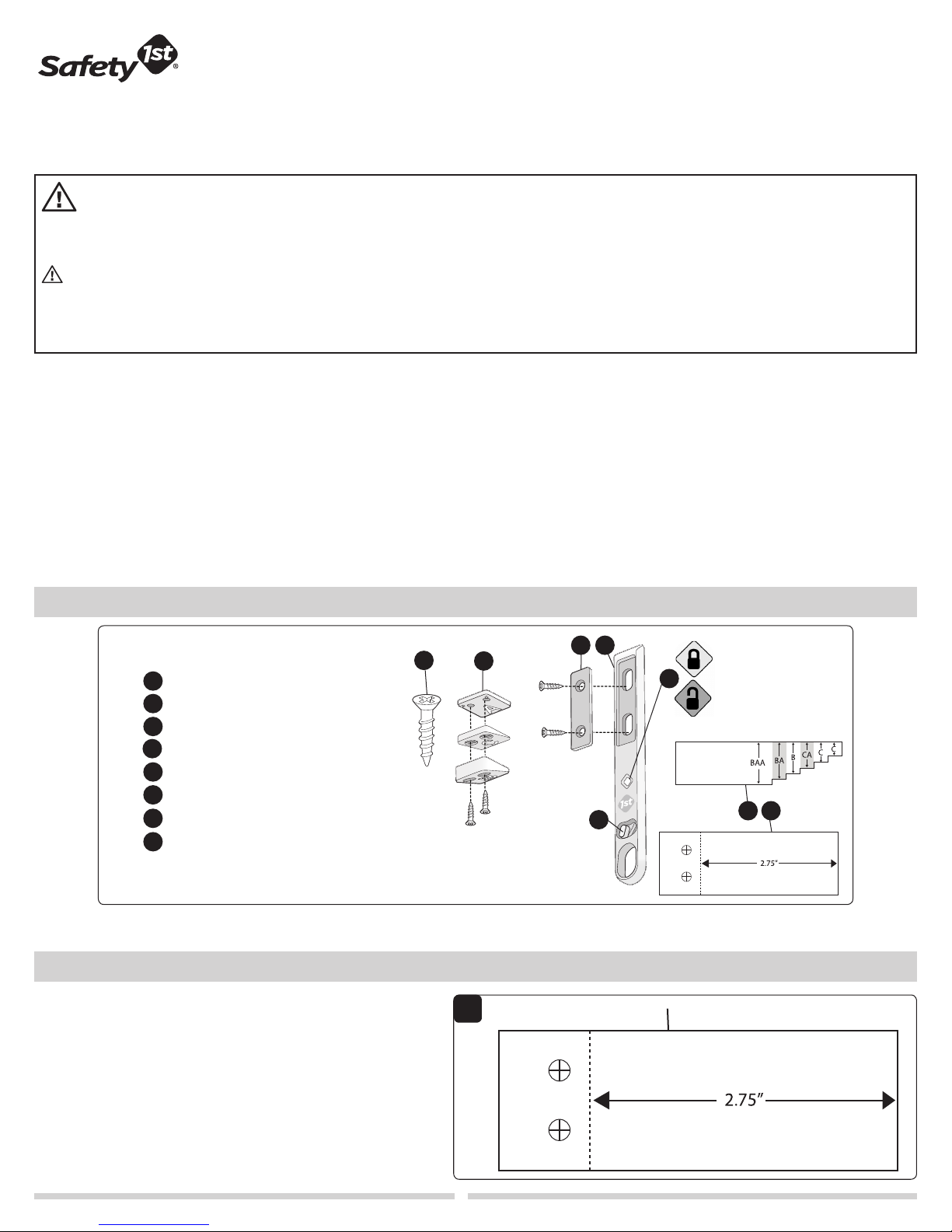
Parts & Features
Spacers (2 “A”, 1 “B” and 1 “C”)
A
Lock plate
B
Lock
C
D
1” Screws (4)
SecureTechTM locking indicator
E
SecureTech™ locking button
F
Spacer installation template
G
Catch installation template (cut
H
out from Figure 1 below)
Prepare to Install
1 Cut out the catch installation template located on this page to the
right
(Figure 1)
.
D
A
E
F
B C
1
Cut out this template
Green = Locked
Red = Unlocked
G H
1
Prepare to Install
(continued)
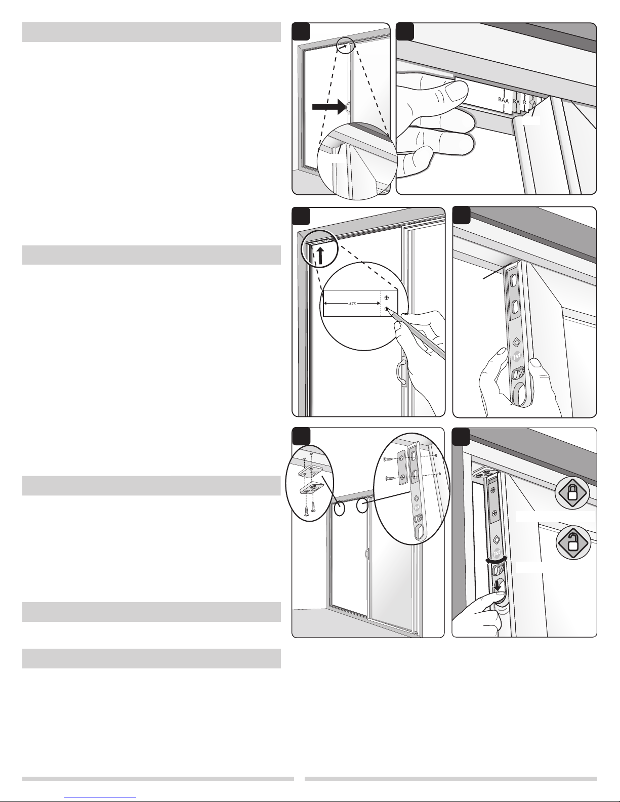
2 Open the sliding door approximately 5” (12.7 cm) and locate the
gap above the sliding door
(Figure 2)
.
3 Determine which spacer(s) you need by inserting the spacer
installation template into the gap
template flat against top edge of track. When a side edge of the
template comes in contact with the top edge of the door, note the
letters on the template. For example, the gap shown in Figure 3
requires two spacers labeled C and A.
(Figure 3)
. Make sure to hold
4 Place the catch installation template at the top edge inside the
track as shown (Figure 4). Make sure template is flat along track
and centered.
5
Use a pencil to poke through and mark two drill locations for the
screws (Figure 4).
6
Line up lock with top of door. Make sure small “L-bracket”
hooks over the top of the door. Make sure it is centered from
left to right (Figure 5). Use a pencil to mark two locations for
the screws.
Remove template.
To Install
2
4
3
Gap
Gap
5
CAUTION: Follow the drill manufacturer’s instructions when using your
drill. Power tools are not recommended for screw installation.
7 Using a
locations.
3/32
” drill bit, predrill 3/4” (
1.9 cm)
deep holes at marked
8 Position spacer(s) with the narrow end(s) toward the center
of the door as shown
to install two screws. If spacer A is used it should go between
spacer C and the track or spacer B and the track depending on
individual needs (Figure 6 inset). NOTE: If spacers B, A, and A
are all needed, place both A spacers together and place them
between spacer B and the track.
(Figure 6)
use Phillips head screwdriver
9 Position lock plate against lock making sure the indents for screw
heads are facing out as shown in the parts and features section
on page 1. Use Phillips head screw driver to install two screws
(Figure 6).
10 Test the lock. Pull down on lock and pivot locking button to the
green locked position and close door to ensure lock closes easily
(Figure 7).
To Use
TO LOCK:
indictor to ensure lock is properly engaged. When correctly
installed, door will only open approximately 2 1/2” (6.4 cm).
Close door. Look for green SecureTechTM locking
TO UNLOCK AND OPEN DOOR:
Pull down on lock (Figure 7) and open door
.
TO DEACTIVATE FOR PERIODS OF NON-USE:
Pull down on lock and pivot locking button to the red,
unlocked position
(Figure 7)
.
6
Position
lock at
top of
door
6
7
Green = Locked
Red = Unlocked
To Remove
To remove the lock, remove screws.
To Clean
Wipe clean. Keep lock dry.
2
 Loading...