

Safeside R-3D2 Series, R-3D2-SR, R-3D2-W5, R-3D2-SRW5 Installation And Operating Instructions Manual

INSTALLATION AND OPERATING INSTRUCTIONS
R-3D2 series Flex-Mount Voltage Indicators
Part Numbers:
Type 3 Phase, 4-Wire 3 Phase, 5-Wire
Flashing R-3D2 R-3D2-W5
Solid-On R-3D2-SR R-3D2-SRW5
UL APPROVED FOR: CLASS I, DIVISION 2 HAZ LOC CAT III & IV
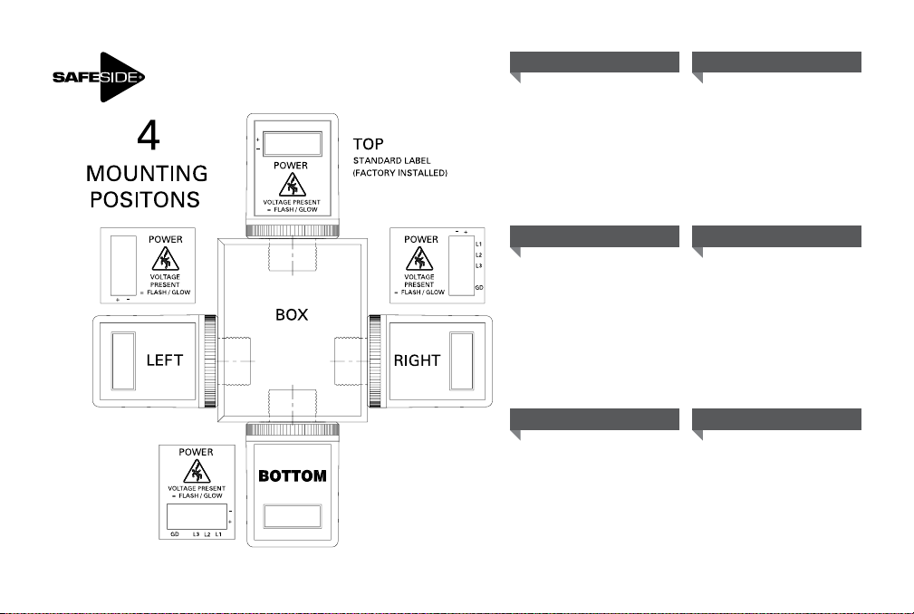
Part Number Description: The R-3D2 series Flex-Mount Voltage Indicator introduces a 90° angle display for
(Top, Right, Left or Bottom) mount thru either M20 or 3/4” size knockouts. (Hardware included)
General Usage: This 3-phase device reduces the risk of electrical arc flash into a HazLoc area by pre-verifying the
electrical isolation from outside of a control panel. Engineered with redundant circuitry, the voltage indicator is
powered by the same voltage that it indicates. The voltage indicator package is externally mounted to one of four
sides of a power disconnect or a motor controller box. The 20mm threaded bushing protects 4 or 5 wires entering
into the box. For proper seal, use either M20 or 3/4”knockouts, follow respective assembly drawing page 4 & 5.
For 3/4” knockout sizes, a 20mm to 3/4” threaded adapter is included. Whenever AC or DC voltage is above detection
thresholds the display indicators will flash or glow.
If the equipment is used in a manner not specified
I-R3D2-IG-0916
by the manufacturer, the protection of the
equipment may be impaired.
- Probability of death or serious injury if accident occurs: COULD
1
For technical questions, contact:
Grace Engineered Products Inc./ 1515, E. Kimberly Rd,
Davenport, IA-52807 / 800.280.9517 563.386.9639 (Fax)
PESD™
www.pesd.com

BE SURE POWER IS SHUT OFF PRIOR TO INSTALLING THIS DEVICE!
PESD™
SAFESIDE
UL NEC CLASS 1, DIVISION 2
AUXILIARY DEVICE SUITABLE FOR USE IN CLASS 1,
DIVISION 2 (or ZONE 2), GROUPS A, B, C, D
HAZARDOUS LOCATIONS, or NONHAZARDOUS LOCATIONS ONLY
Class I Groups :
A- acetylene
B- hydrogen
C- ethyl-ether vapors, ethylene or cyclopropane
D- gasoline, hexane, naptha, benzene, butane, propane, alcohol, acetone, benzol, lacquer solvent vapors,
or natural gas
Division 2 : Ignitable concentrations of gases, vapors, or liquids are not likely present under normal operating
conditions
Haz Loc Normal Atmospheric Conditions : a) -25C to +40C ambient b) 21% Max. Oxygen
concentration per volume c) barometric pressure range of 80 kPa (0.8 bar) to 110 kPa (1.1 bar)
EXPLOSION HAZARD – DO NOT DISCONNECT
EQUIPMENT WHILE THE CIRCUIT IS LIVE OR UNLESS THE AREA IS KNOWN
TO BE FREE OF IGNITABLE CONCENTRATIONS.
®
Flex-Mount Voltage Indicator R-3D2
Patented
2

Environmental Ratings
PESD™
Overvoltage Category: CAT III 1000 V & CAT IV 600 V per UL61010, 3
Safety category ratings are important, differences and limitations are as follows:
CAT III 1000 V –rating allows up to 1000-V phase to ground with distribution level wiring, 480-volt
and 600-volt circuits such as 3-phase bus and feeder circuits, motor control centers, load centers and
distribution panels. Also included in CAT III are switchgear, motors, transformers and similar fixed
loads, and loads that can generate their own transients.
CAT IV 600 V - rating means that it is suitable for use in all locations such as 3-phase utility or outdoor
wiring on conductors that have up to 600-V phase to ground. Applications may include overhead or
underground lines that power detached buildings or underground lines that power well pumps.
Transient Withstand: Both CAT III & CAT IV ratings are tested to withstand an 8,000-V transient
overvoltage event from a 2 ohm source.
Pollution Degree: 2 - Equipment being evaluated to 60950, Laboratories, Test Stations,
Office Enviroment
NEMA Enclosure designation: - UL TYPE
TYPE 4X Either indoor or outdoor use to provide a degree of protection against falling rain, splashing
water, and hose-directed water, undamaged by the formation of ice on the enclosure; resists corrosion.
TYPE 12 Indoor use to provide a degree of protection against dust, dirt, fiber flyings, dripping water, and
external condensation of noncorrosive liquids.
TYPE 13 Indoor use to provide a degree of protection against lint, dust seepage, external condensation
and spraying of water, oil, and noncorrosive liquids.
Ingress Protection: IP67
First digit 6 = Dust-Tight. Second digit 7 = Protected against short periods of immersion in water.
Operating maximum altitude: 5000 meters (UL’s testing limit)
Humidity: 95% RH @ 1,000 hours
3
RD
Edition

PESD™
Mounting Instructions for M20 Knock-Out Mount
Control Dwg # 206,
R-3D2
MA
4

PESD™
Mounting Instructions for 3/4” Knock-Out Mount
Control Dwg # 207,
L1
L3
R-3D2
N
(WYE Only)
GD
L2
MA
5

PESD™
1. Follow all Local, State, and National Electrical Codes when installing this equipment. The installation must be in
accordance with the Associated Location restrictions of the National Electric Code or Canadian Electrical Code as
applicable, including issues such as the routing, support and length of the involved cord of cable. All wiring shall be
enclosed and routed in accordance with Class 1, Division 2 wiring methods as specified in Article 501-4(B) in National
Electrical Code, NFPA 70. Overcurrent protection of the supply leads may be necessary. When determined necessary, use
a low .1A or .125A 600VAC fast acting fuse like KTK-1/10 or -1/8. Devices are intended to be panel or surface mounted.
The installation shall be used on a clean flat surface of a type 4X, 12, 13,or IP67 enclosure, or equivalent elevated ambient
rating.
2. The disconnecting means must first be suitably located and easily reached; and it must be marked as the disconnecting
device for the equipment. The Housing Front Display must be in visual proximity to the control panel ON/OFF disconnect.
Make sure to allow for enough wire length to properly route it back to the intended terminal locations with all necessary
bends. A minimum wire length of 6” must be maintained.
3. For 20mm KO mount, preassemble the small o-ring and channel ring (see PG. 4). For 3/4” KO mount, preassemble both
o-rings and threaded adapter (see PG. 5). For the best o-ring sealing performance, verify the external contact surface
around the panel knockout is clean, flat and free of debris. Feed wires through both KO hole and respective nut on the
inside. Tighten the nut before wiring (refer to Nut Torque PG. 8).
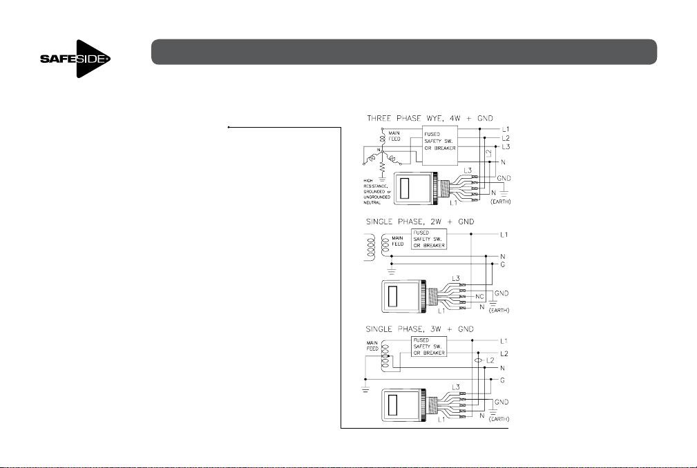
4. For Delta configured power, connect the 1 bar, 2 bar & 3 bar coded black wires (See PG. 9 Fig. 1 wire code) to L1, L2, & L3
respectively on the fused or disconnect side of the 3-Phase line voltage ( PG. 11). The Green/Yellow stripe (Grn/Yel) wire
MUST be connected to Earth Ground.
5. For Wye configured power with Neutral, use a 3-P WYE 5-WIRE device (see page 13 applications). The White wire
connects to neutral (N) and the GRN/YEL (GND) must connect directly to Earth Ground
(see PG. 9 Fig. 2 wire code).
OPERATING INSTRUCTIONS
INSTALLATION &
6
M20
METRIC 20MM
(0.79 DIA)
3/4”
ACTUAL SIZE
(1.115 DIA)

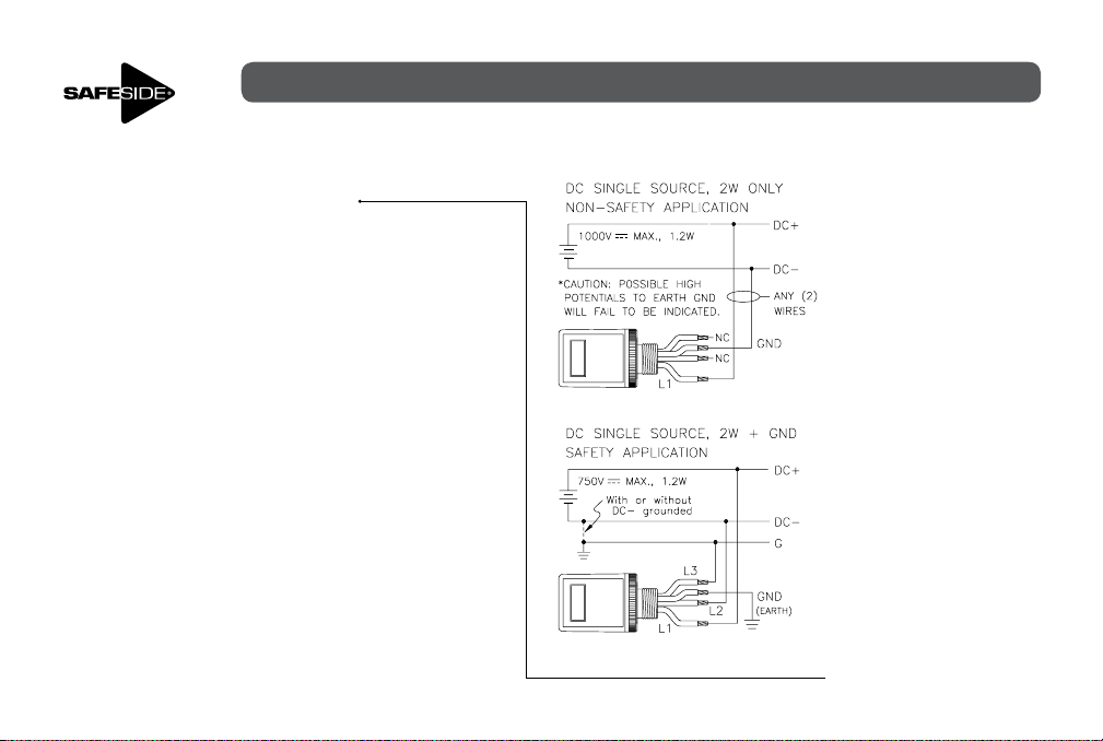
6. For DC configured power see “DC Applications” on pages 12 & 14.
7. Verifying Proper Operation: First disconnect all equipment that may introduce a hazard and notify personnel
before powering the panel!
TURN POWER ON. With up to 600V 3~ applied, the L1, L2, and L3 indicators should flash or glow according
to respective model “FLASH RATE” Specifications on PG. 15 & 16. The type of power system grounding
configuration determines if the GND indicator normally indicates (See GND Indicators, PG. 15).
8. TURN POWER OFF. All indicators should be extinguished. Note: If only a single LED illuminates for any (2)
indicator pairs, STORED ENERGY is likely present and must be removed or discharged. All indicators must be
extinguished or a shock hazard is present on the monitored lines.
9. To complete proper installation, verify proper grounding of the GND lead-wire.
Use this procedure to insure proper grounding:
a. Complete normal installation and apply power to the R-3D2, if the GND LEDs do not illuminate, proceed
to step b.
b. Remove power and re-establish an electrical safe work condition to allow one phase lead-wire to be discon-
nected from its source by either disconnecting wire or pull a fuse.
c. Re-apply power and verify that the GND LEDs and Neutral (N) LEDs for Wye models now illuminate. If not,
remove power & provide current with a 1M-2M ohm 1W resistor temporarily connected from any phase to
ground. Repeat step c.
d. To complete installation, disconnect power before removal of step c.) resistor & to restore the phase
lead-wire or fuse. Reapply power to reverify that L1, L2, & L3 LEDs illuminate.
BEFORE OPENING A PANEL, TURN POWER OFF! (Steps 1-9 must first verify proper operation of indicators.)
SAFETY PROCEDURES STILL APPLY: Before working on an electrical conductor, verify zero electrical energy with
proper voltage testing instrument and the proper procedure as per NFPA 70E 120.1(5), 120.2 (F)(2)(f)(1-6), OSHA
1910.333(b)(2)(iv)(B).
7

Maintenance: A clear view of the front indicator window must be maintained. Removal of dust,
grime, or other contaminents should preformed by gently wiping them off with a clean damp cloth.
PESD™
If power cannot be removed, use insulative gloves. Do not use harsh chemicals.
O-ring inspection/replacement: See pg. 4 or 5 for details, the mounting K.O.
hole size determines the DWG #.
M20 K.O.: CONTROL DWG #206
3/4” K.O.: CONTROL DWG #207
Nut Torque: The nut tightening torque required to maintain seal with full o-ring compression is
about 10 in-lbs. However, this torque level can still allow the housing to be manually rotated.
Tightening torque must be increased further to around 15 to 30 in-lbs in order to restrict rotational
movement to a minimal amount. With moderate rotational hand force, it is normal for the o-ring
to allow a little cushioned amount of back and forth movement but should not allow continued
rotation.
Weight: 12 oz. \ 0.34 kg
Note: Product weight includes mounting hardware, manual and packing materials are excluded.
8

MEASURING EQ. 46RD
HAZ. LOC. 42 RV
TYPE 13
EXPLOSION HAZARD – SUBSTITUTION OF ANY COMPONENT MAY
PESD™
Approvals:
UL LISTED file No. E334957
Per ISA 12.12.01-2007
CAT REPORT No. E188860-A3
per UL61010-1, 3RD Edition
CAN/CSA- C22.2 No. 61010 -1, 3RD Edition
Input AC SINGLE or 3-P DELTA or WYE:
20 to 600VAC 3 , Line-to-Line, 50/60/400 Hz
DC OR STORED ENERGY:
20 to 100 0VDC
Maximum Rating 750VAC
Detection Flashing : 14VAC
Thresholds Solid- ON : 15VAC 3 , 19VAC 1 , 17VDC (typical cut- off’s)
Temperatures Operate : -20C to +55C, Code T6
Storage : -45C to +8 5C
Terminations 3 Ft. Stranded Cu. Wires, 12 AWG 90° @1000V,
UL-1452 PVC Insulation w/ nylon jacket
Wire 4-Wire : L1- L3: BLK w/ bar code, GND: Grn/ Yel (Fig. 1)
5-Wire : L1- L3 + N: BLK w/ bar code, GND: Grn/ Yel, N: Wht Neutral (Fig. 2)
Indicators 4-Wire : (6) Red L1-L3, (2) Amber GND LEDs, Fully Encapsulated
5-Wire : (6) Red L1-L3, (4) Amber N & GND LEDs, Fully Encapsulaed
Enclosure Threaded Base & Channel Ring Lexan 94 0 BLK,
Cover Lexan 94 3
Totally Encapsulated for Environment Protection
O-Ring Seals #118 & #123 Blue FVMQ Flourosilicone,
UL approved material
3
or 1000VDC @ 1.2 Watts, Operating Ambient Air of 55°C Max.
IMPAIR SUITABILITY FOR CLASS I, DIVISION 2
CAT III 1000V
CAT IV 600V
DC or AC-rms to Ground
(Peak Impulse Transient 8000V
20 repetitions, 2 ohm source)
, (Voltages Line-to- Line or Line -to-Ground)
3
, 18.5VAC 1 , 15VDC (typical cut-off’s)
9
IP67
UL TYPE 4X
TYPE 12
IND. CONT. EQ. 496Y
3 Phase, 4- Wire
Fig. 1
3 Phase, 5- Wire
Fig. 2
SYMBOL IDENTIFICATIONS
3
3 Phase AC rms DC Volts
Electric Shock Danger of Death
Caution Double Insulated Symbol
GD
L3
L2
L1
Fig. 3
(3-P Delta 4-Wire
version shown)
PESD™
L1
L3
L2
GD
DISCONNECT
LABEL ACCESSORIES
(3) Optional labels are included:
RIGHT, LEFT, and BOTTOM.
The TOP label comes factory
installed. Should a rotation of
text be preferred, the label area
is double recessed for an overlay
the label of choice.
For good adhesion, follow the
Label Application Instructions.
An alcohol prep pad is included.
GERÄTEETIKETTEN ALS ZUBEHÖR
(3) Optionale Etiketten werden
mitgeliefert:
Für: RECHTS, LINKS und UNTEN.
Das OBERE Etikett ist bereits
ab Werk angebracht. Sollte
es wünschenswert sein, die
Textrichtung zu verdrehen, ist
die Fläche für das Etikett doppelt
vertieft, damit das gewünschte
Etikett darüber angebracht werden
kann.
Die Anweisungen zum Anbringen
der Etiketten befolgen, damit
diese gut anhaften. Ein in einer
Alkohollösung getränktes Pad wird
mitgeliefert.
ETIQUETAR ACESSÓRIOS
(3) Etiquetas opcionais estão inclusas:
DIREITA, ESQUERDA e PARTE
INFERIOR. A etiqueta da parte
SUPERIOR foi instalada na fábrica.
Caso preferir girar o texto, a área da
etiqueta é de duplo rebaixamento,
para superpor a etiqueta de
preferência.
Para uma boa adesão, seguir as
Instruções de Aplicação de Etiquetas.
Uma almofada preparada com álcool
está inclusa.
ACCESORIOS DE ETIQUETADO
(3) Etiquetas opcionales incluidas:
DERECHA, IZQUIERDA y ABAJO.
La etiqueta ARRIBA (TOP) viene
instalada de fábrica. Si prefiere un
texto rotado, el área de etiquetas
tiene un doble rebaje para que
pueda superponer la etiqueta que
prefiera.
Para una buena adhesión, siga
las instrucciones de Aplicación
de etiquetas. Se incluye una
almohadilla humedecida con
alcohol.
ÉTIQUETTES
(3) Les étiquettes optionnelles
suivantes sont comprises :
DROITE, GAUCHE ET BAS.
L’étiquette du HAUT est posée
à l’usine. La zone d’installation
de l’étiquette comporte un retrait
double pour permettre sa pose selon
l’orientation du texte sélectionnée.
Pour assurer une bonne adhésion
de l’étiquette, suivre les directives
de pose. Un tampon alcoolisé de
préparation de la surface est compris.
ACCESSORI ETICHETTE
(3) Sono comprese delle etichette
opzionali:
DESTRA, SINISTRA e BASSO.
L’etichetta ALTO è installata in
fabbrica. Qualora si preferisca
una rotazione del testo, la zona
dell’etichetta è incassata per
permettere la sovrapposizione
dell’etichetta scelta.
Per una buona aderenza, seguire
le istruzioni sull’applicazione delle
etichette. È compreso un tampone
ad alcool.
10

PESD™
WIRING INSTRUCTIONS
• R-3D2/R-3D2-SR
AC APPLICATIONS
11
PESD™
WIRING INSTRUCTIONS
• R-3D2/R-3D2-SR
DC APPLICATIONS
12
PESD™
WIRING INSTRUCTIONS
• R-3D2-W5/R-3D2-SRW5
AC APPLICATIONS
13

PESD™
WIRING INSTRUCTIONS
• R-3D2-W5/R-3D2-SRW5
DC APPLICATIONS
14

NEUTRAL (N) and/or GND Indicators explained:
PESD™
The LED indicators are current driven; therefore, no net current in a neutral and/or ground line
to the device will cause the respective indicator pairs to not glow or flash. For isolated 3-Phase
Delta or Wye applications, it is normal for the “GND” indicator pair to not flash since a current
path to ground is not present in an isolated system. Unless a phase is lost or an unbalanced
condition is created, current may likewise be insufficent for the “N” indicator pair to flash or
glow. This peculiarity results when the Phase-to-Phase voltages are balanced resulting in no net
current to a Neutral connection.
GND DETECTOR THRESHOLDS
(LEAKAGE ANY PHASE-TO-GND OR -N)
FLASHING
INDICATOR FLASH RATES
(L1,L2,L3, N, GND)
3
LINE-TO-LINE (VAC)
L1,L2,or L3 TO GND CONTINUITY (OHMS) 2M 5M 7.5M 13M 20M
DETECTOR INDUCED FAULT CURRENT ( A) 4 12 17 20 21
3
LINE-TO-LINE or -N VAC
FLASHES/SEC (TYPICAL) 0 0.9 2.6 3.3 3.7 3.8 3.9
OR STORED ENERGY (VDC) <15 20 48 110 300 600 1000
FLASHES/SEC (TYPICAL) 0 0.9 1.9 3.2 3.7 4.0 4.0
<14 20 120 240 480 600 750
20 120 240 480 750
GND DETECTOR THRESHOLDS
(LEAKAGE ANY PHASE-TO-GND OR -N)
SOLID ON
INDICATOR FLASH RATES
(L1,L2,L3, N, GND)
3
LINE-TO-LINE (VAC)
L1,L2,or L3 TO GND CONTINUITY (OHMS) 2M 3.5M 5M 9M 14M
DETECTOR INDUCED FAULT CURRENT ( A) 4 16.5 24 29 30
3
LINE-TO-LINE or -N VAC
FLASHES/SEC (TYPICAL) 0 8.0 36 60 61 66 68
OR STORED ENERGY (VDC) <17 20 48 110 300 600 1000
FLASHES/SEC (TYPICAL) 0 10 25 36 50 58 60
15
<15 20 120 240 480 600 750
20 120 240 480 750

16

INSTRUCCIONES DE INSTALACIÓN Y OPERACIÓN
PESD™
R-3D2 series Flex-Mount Voltage Indicators
TABELLA CODICI PRODOTTI
Type 3 F DELTA 4 HILOS 3 F ESTRELLA 5 HILOS
DESTELLANDO R-3D2 R-3D2-W5
ENCENDIDO PERMANENTE R-3D2-SR R-3D2-SRW5
HOMOLOGADO POR UL PARA: CLASE I, DIVISIÓN 2, ÁREAS PELIGROSAS CAT. III y IV
Descripción de número de parte: La serie R-3D2 presenta una pantalla con un ángulo de 90° para montaje arriba, derecho, izquierdo o
abajo, a través de agujeros preperforados de tamaño M20 o 3/4”. (incluye los componentes de montaje)
Uso general: Este dispositivo trifásico reduce el riesgo de una descarga disruptiva en un área peligrosa al verificar previamente el
aislamiento eléctrico desde el exterior de un tablero de control. Con un diseño de circuitos redundantes, la Alerta de presencia de
voltaje está alimentada con el mismo voltaje que indica. El paquete del indicador de voltaje se instala externamente en uno de los
cuatro lados de la caja del seccionador de alimentación o de la caja del controlador del motor. El buje roscado de 20 mm protege a
4 o 5 conductores que entran en la caja. Para un sello adecuado, utilice los agujeros preperforados M20 o 3/4” y siga los respectivos
planos de montaje de las páginas 20 y 21. Para agujeros preperforados de 3/4” se incluye un adaptador roscado de 20 mm a 3/4”.
Cada vez que el voltaje de CA o CC esté por encima del umbral de detección, los indicadores de la pantalla destellarán o brillarán.
ADVERTENCIA
Si el equipo no se utiliza de la manera
especificada por el fabricante, la protección
del equipo puede no ser efectiva.
- Probabilidad de muerte o lesiones graves si
ocurre un accidente: POSIBLE
Si tiene alguna consulta técnica,
póngase en contacto con:
Grace Engineered Products Inc./ 1515,
E. Kimberly Rd, Davenport, IA-52807. /
PESD™
800.280.9517 563.386.9639 (Fax)
17
www.pesd.com

¡ASEGÚRESE DE QUE LA ALIMENTACIÓN ESTÉ DESCONECTADA ANTES DE
PESD™
INSTALAR ESTE DISPOSITIVO!
SAFESIDE
®
Flex-Mount Voltage Indicator R-3D2
UL NEC CLASE I, DIVISIÓN 2 Patentado
“DISPOSITIVO AUXILIAR ADECUADO PARA USO SOLO EN ÁREAS
ADVERTENCIA
Clase I Grupos:
A - acetileno
B - hidrógeno
C - vapores de éter etílico, etileno o ciclopropano
D - gasolina, hexano, nafta, benceno, butano, propano, alcohol, acetona, benzoilo, vapores de solventes de laca
o gas natural
División 2: Bajo condiciones normales de operación no es probable que se presenten concentraciones combustibles de gases, vapores o líquidos
Condiciones atmosféricas normales en áreas peligrosas: a) Temperatura ambiental -25 °C a +40 °C b) Máx.
concentración de oxígeno por volumen 21% c) Rango de presión barométrica de 80 kPa (0,8 bar) a 110 kPa (1,1 bar)
PELIGROSAS CLASE I, DIVISIÓN 2 (o ZONA 2), GRUPOS A, B, C, D
o en ÁREAS NO PELIGROSAS”
PELIGRO DE EXPLOSION - NO DESCONECTE EL EQUIPO MIENTRAS EL CIRCUITO ESTÉ ENERGIZADO, A MENOS QUE SE CONOZCA QUE EL ÁREA NO
PRESENTA CONCENTRACIONES INFLAMABLES.
18
 Loading...