

Safeplace T500 C, M800 C, T800 C, M500 C, T300 C Technical Manual & Handheld Unit Manual
...
TQM Technical Manual
Handheld Unit Manual
For models: M800 - C,C4,SL,W,MS,E
&
T800 - C,C4,SL,W,MS,E
M500 - C,C4,SL,W,MS,E
T500 - C,C4,SL,W,MS,E
T300 - C,C4,SL,W,MS,E
Q300 - C,C4,SL,W,MS,E
M300 - C,C4,SL,W,MS,E
IMPACT - C,C4,SL,W,MS,E
590.1060.001
Version 05 – 2.09

2

Registration Form
Please fill in this form and fax it to the
following number: +972 8 85 73 962
or email to sales@safeplace.co.il
Property name:__________________________________
Chain/Group:___________________________________
Address:__________________________________________________________
_________________________________________________________________
_________________________________________________________________
Contact persons:____________________________________________________
_________________________________________________________________
Telephone number:______________________________
Fax number:___________________________________
Email:________________________________________
Safe model________________ Quantity __________________
Color_________________________________________
3

4

Table of Contents
1 General Description and Guidelines Page 7
2 Safety Instructions Page 8
3 Safe Models Page 10
4 Anchoring the Safe Page 11
5 Emergency Opening Procedure Page 12
Page 13Emergency Opening with EOT 3005a
Page 14Emergency Opening with BiMax Handheld Unit5b
Page 15Emergency with Master Key/Card5c
6 Mechanical Emergency Opening for C, C4, SL, W Page 16
7 Mechanical Emergency Opening for E4, MS4 Page 17
8 Trouble-Shooting Page 18
Page 21Trouble-Shooting for Magna 500
9 Battery Replacement Page 22
10 Parts Replacement Page 23
10a Electronic Board Page 24
10b Battery Housing Page 25
Page 26Lock Assembly10c
Page 28Panel Assembly10d
Page 30Door Replacement10e
11 Safe Place Components
11a C, C4, SL, W Page 31
11b E4, MS4 Page 32
11c Assembled Door C, C4, SL Page 33
11d Assembled Door E4, MS4 Page 34
5

6

General Description
And Guidelines
Dear Customer,
You have just received new safes. In the following manual, you will find
all the necessary information for operating and maintaining the
safes, including:
1. Safety instructions.
2. Anchoring - The different options for anchoring the safes.
3. Emergency opening.
4. Parts replacement - How to replace the main components of the
safe.
5. Safe Place components - All the safe components you may
need to purchase in the future. Please note which size safe
(C, SL, MS, E & W) you have, and choose the component.
6. Trouble-shooting - safe feedback that will identify the problem in
a malfunctioning safe.
Service and Warranty Guidelines:
We provide a 2 year limited warranty for parts. You received
spare parts to enable you to replace any defective part. We ask
you to please send us any defective parts for later replacement.
If you have any questions or need assistance, please call your
local distributor. If for any reason you cannot reach your local
distributor, you can always contact us at fax number: ++972-88573962, or e-mail: service@safeplace.co.il
7

Safety Instructions
For safes with power outlet (recharge socket)
The safe model you have purchased is equipped with a 220V or
110V power (USA Rating : 110V 5A 60Hz) outlet for laptop
recharging. Please follow the safety instructions carefully before
hooking up the power outlet.
1. Only a certified electrician should handle this equipment.
2. Unplug the receptacle from the wall outlet before performing
maintenance.
3. If no plug is connected to the electrical wire – connect as follows:
U.S.A:
Black wire to terminal marked L
White wire to terminal N
Green wire to terminal E or GR
:Europe
Brown wire to terminal marked L or
Blue wire to terminal marked N
Green & yellow wire to terminal marked E or
4. The receptacle must be protected by a 6 Amp fuse.
5. Do not plug it in if for any reason, the power supply cord or plug
is damaged or frayed.
6. Do not allow anything to rest on the power cord.
8

Safety Instructions
For safes with AC power hook-up (Adaptor)
Adaptor specifications AC-DC:
Output – 9V DC, 500mA max. built in thermal fuse.
1. Only a certified electrician should handle this equipment.
2. Pay attention to wire marks (+ / -) and assemble them
properly.
3. Disconnect the adaptor from the main power before replacing
the electronic board.
4. Check the adaptor specifications before plugging into main
power (see above).
9

Safe Models
Biometric
Digital Safes
Magna 800
Magna 500
Magna 300
Impact
Combination
Titan 500
Card Safe
Titan 800
Smart Key
Quantor 300
Tiara-M Top Open
C - Small
SL – Super Laptop
MS – Medium
C4 - Laptop
W – Wall
E – Floor
10
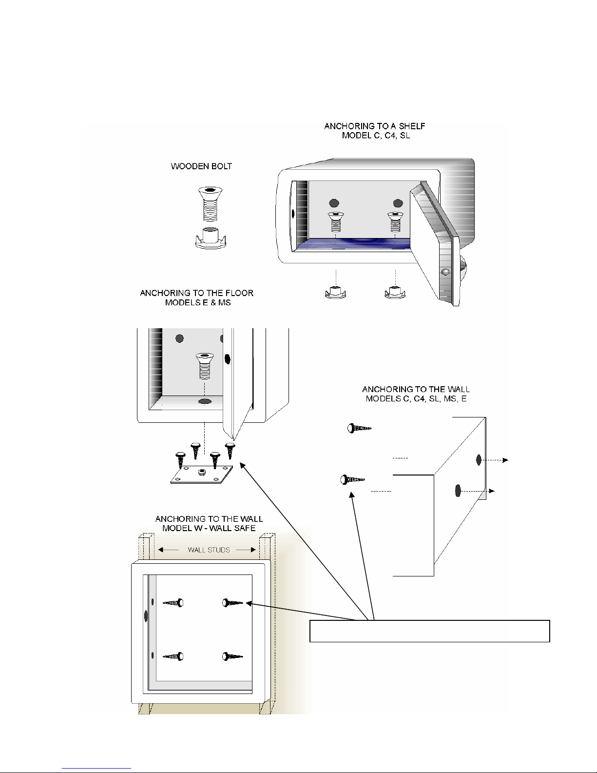
Anchoring The Safe
Anchoring Bolts should be - 10*1”
11

Emergency Opening Procedure
In case the safe is locked and
the guest is unable to open it,
observe the following procedure:
1. Perform the override procedure with the BiMax
Handheld Unit or Emergency Opening Tool T300 (see
details on following pages). If the safe does not open,
go to step 2.
2. Make sure your HHU/EOT and Master Card/iButton
are working properly. Test them on another safe.
3. If the above does not help, perform mechanical
opening.
Before performing the mechanical opening, we highly
recommend contacting your local service
representative for assistance.
12

Override Procedure With EOT 300
(Emergency Override Tool)
1. Plug-in the EOT – The
green led will light up.
2. Place the Master (red)
iButton on the rounded
reader within 6 seconds.
3. If you have an error (red
light) press Clear button
and try again.
A green light will blink and
the safe will open!
13

Override Procedure
With BiMax Handheld Unit
Please Also See Page 7 of Override and Audit Handheld Unit Manual in this
Booklet
1. Turn the Handheld on by
pressing the ON button, enter
your password and put your
finger on the reader.
2. Select Override Safe
and press ENTER.
3. Connect Safe And Press
Enter appears on the
display. Connect the
Handheld plug to the
underside of the safe keypad
and press ENTER.
4. Attach iButton appears on
the display. Attach the
master iButton.
The safe will open!
14

Override Procedure
With Master Key/Card
Titan 300/800/500 models:
Slide the Master card from
left to right with
magnetic stripe up.
The safe will open!
Quantor 300 model:
Place the Master (red)
iButton on the iButton
reader.
A green light will blink
and safe will open!
15

Mechanical Emergency Opening
For C, C4, SL & W Models
THE DRILLING PROCEDURE IS THE LAST OPTION FOR OPENING THE SAFE.
PLEASE MAKE SURE YOU TRY ALL OTHER OPTIONS BEFORE DRILLING!
1. Place the drilling template on the left
bottom corner of the safe door.
1a. For Titan Models, forcibly remove the
panel to place the drilling plate.
1b. For left hand doors, place the template
at the upper right corner.
1 c. For W left hand doors, forcibly remove
the panel and place the template at the
upper right corner.
2. Drill 3 holes with a 4 mm drill through the
template.
3. Remove the template and enlarge the
holes to 8 mm.
4. Drill through the head of the screws all the
way until the the lock assembly moves
backward.
The safe will open!
16

Mechanical Emergency Opening
For E4 & MS4 Models
THE DRILLING PROCEDURE IS THE LAST OPTION FOR OPENING THE SAFE.
PLEASE MAKE SURE YOU TRY ALL OTHER OPTIONS BEFORE DRILLING!
1. Place the drilling template on the left
bottom corner of the safe door.
2. Drill a 4 mm hole through the template.
3. Remove the template and enlarge the
holes to 8 mm.
4. Drill through the head of the screws all the
way until the lock assembly moves
backward.
The safe will open!
17

Trouble-Shooting 1
Check Microswitch. Close door.
Check Microswitch. Close door.
For Magna 800, Titan 800 and Titan 500 Models:
Safe series 500 and 800 have a built in diagnostic system which
shows error numbers on the display if there is any problem
with the safe.
The following list is available in the Tools Menu of the HHU.
Display Problem Description Operation Instructions
Common Operational Problems
Code Wrong code Enter code again. Try another code.
Batt Low Batteries Replace batteries
Er00 Clock is not set Set Safe Clock
Er01 Card error Slide card again or replace card
Er02 Bolt cannot lock Push door. Release bolt.
Er03 Bolt cannot open Push door. Release bolt.
Er04 Not enough digits Enter 4 digits
Er05 Activator needed Plug Activator
Er06 Wrong Override Change override unit
Er07 Bolt in middle position Override safe. Check lock assembly.
Er08 Illegal card Use another card
Er10 Door Microswitch open
Er11 Card error Slide card again. Replace card.
Er12 Button Error Re-attach button. Replace button.
Er13 Wrong Operation Enter 4 digits to open
Er14 Door Microswitch Open
Er16 Wrong Master Use different master
Er17 Common code Enter non-common Code
Er18 Common code Enter non-common Code
Er20 Comm. Failure Check HHU connection. Try again
Er21 Comm. Failure Check HHU connection. Try again
Er22 Comm. Failure Check HHU connection. Try again
Er23 Comm. Failure Try again
Er24 Comm. Failure Try again
Er25 Override failed Start override process again
Er26 Illegal operation Start override process again
Er27 Wrong IR key Use card or press CLR button
Er28 Wrong IR key Use iButton or press CLR button
Communication Problems
18

Trouble-Shooting 2
Display Problem Description Operation Instructions
Override Problems
Er30 Unit disabled Use different type of override
Er31 Master disabled Use override unit or code
Er32 Wrong master Use iButton or code
Er35 Wrong master Use card or code
Er36 Master disabled Use different type of override
Er37 Memory problem Replace main PCB
Er38 Master defin. Err. Factory Error
Er39 Memory problem Try process again.
Operational Problems in Dual Safes
Er40 Wrong key Open with code or card
Er41 Button disabled Use code or card
Er42 No Code Entered Enter code and lock
Er43 Wrong key Open with code or iButton
Er44 Wrong key Open with card or iButton
Er45 Illegal Operat. Use code or iButton
Er46 Illegal Card Use different card
Er47 Illegal Button Use different iButton
Er48 Keypad disabled Use card or iButton
Er50 Keypad disabled Use card or iButton
Manufacturer Problems
Er64 No master defined Factory Error
Er66 Master defin. Err. Factory Error
Er67 Master defin. Err. Factory Error
Er68 Master defin. Err. Factory Error
Er70 Software error.
Er71 Illegal Time Check designated operation time
Er73 Card Unauthorized Try to close with a different card
Er74 Can't Add Card Card already registered
Er75 Can't Add Card Illegal user card
Er76 Can't Delete Card Not a registered card user
Er77 Factory Error Factory Error
Er78 Can't Add Card Memory full
Er79 Add/Del Time Ended Start process again
Er80 Bad Card Can't register this card
Er81 Factory Error Factory Error
Er82 Factory Error Factory Error
Er83 Can't Close with This Card Illegal user card
Er84 Memory problem Replace main PCB
Er85 Memory problem Replace main PCB
19

Trouble-Shooting 3
Anti-Tamper Problems
Er90 Motor tampered Override safe. Check lock assembly.
Er91 Motor tampered Override safe. Check lock assembly.
Er92 Motor tampered Override safe. Check lock assembly.
Er93 Motor tampered Override safe. Check lock assembly.
Er94 Motor tampered Override safe. Check lock assembly.
Er95 Motor tampered Override safe. Check lock assembly.
Er96 Audit Tampered Read from safe. Initiate Safe Data.
Er101 Motor tampered. Override safe. Check lock assembly.
20

Trouble-Shooting for Magna 500
• Safe clock is not initialized. Use the Handheld
Unit to initialize it. (INIT. SAFE DATA)
• The locking bolt won’t eject all the way to lock.
Make sure the door is properly closed and
nothing stops the bolt from moving smoothly.
Check the lock assembly. Check connection of
lock assembly to the electronic board.
• The locking bolt won’t reject all the way to open.
Press the door to release any pressure on the
bolt.
• Not enough digits were entered for locking.
Enter a complete number. If this happens
during override procedure, it means the safe
does not recognize the override unit. Check the
connectors with the unit.
• Wrong master card. Locate the correct card.
• Locking bolt is in middle position. Perform
override procedure.
• Override procedure was not completed. Start
from the beginning.
• Safe has performed an illegal operation. Check
the safe motor and then perform override
procedure.
21

Battery Replacement
C, C4, SL
W, Special Sizes
E, MS
1. Unscrew the cover bolts and remove the door
cover.
2. Remove the old batteries and install the new
batteries. Make sure the batteries point in the
right direction.
3. For safes with Audit function – you must set safe
clock by using the HHU after replacing batteries.
4. Batteries should be replaced every two years.
5. Use only Alkaline Batteries!
22

Parts Replacement
After trouble-shooting the safe, the next step is replacing the
defective part. The safe mechanism is made up of four
components:
Electronic Board
Battery Housing
Lock Assembly
Panel Assembly
The Elimination Method
If you are still not sure where the safe problem lies after the
trouble-shooting process, you should replace the four
components, one after the other, until you discover the
defective component. When performing this process, make
sure that your spare parts are in working order and the
connectors are properly connected. Replace one component
at a time. If the problem is not solved, put the component
back in the same order and then continue to the next
component.
23

Electronic Board Replacement
1. Unscrew the 3 electronic
board screws.
2. Carefully disconnect all
the connectors from the
panel assembly, locking
assembly, and battery
housing assembly.
C, C4, SL
W, Special Sizes
3. Replace the new board
carefully, and connect it
in the same order. After
checking that the door is
functioning properly,
reconnect the screws
(Safes with audit function
should be initialized
before use).
E, MS
24

Battery Housing Replacement
1. Disconnect the
battery housing
connector.
2. Unscrew the two
battery housing
screws.
3. Replace the new
battery housing.
C, C4, SL
W, Special Sizes
4. Replace the plastic
base.
5. The Universal Kit
used in W & special
size safes has builtin battery housing.
Replace the entire
kit.
E, MS
25

Lock Assembly Replacement
C, C4, SL
E, MS
1. For MS & E - remove the electronic board & the battery housing.
2. Unscrew the 4 (E4) or 6 (MS4) nuts.
3. For C, C4, & SL - unplug the lock assembly connector from the
electronic board.
4. Remove the 5 star rings (They cannot be reused.)
26

Lock Assembly Replacement
Universal Kit - W, Special Sizes
1. Remove the
electronic board.
2. Unscrew the 4
nuts which attach
the Universal Kit.
3. Unscrew the 3
bolts which attach
the motor base to
the Universal Kit
(from the back).
4. Make sure the
spring that pulls
back the motor
base is in place
when you
unscrew the
bolts.
27

Panel Assembly Replacement
1. Remove the electronic
board.
2. Unscrew the 4 keypad
panel screws.
3. Replace the new panel
carefully. Make sure
the flat cable runs
freely from the panel
into the door and is
connected to the
electronic board
properly. After
checking that the safe
is working properly,
screw back the panel
and electronic board
screws.
E, MS
E, MS
E, MSE, MS
C, C4, SL
C, C4, SL
C, C4, SLC, C4, SL
28

Panel Assembly Replacement
Universal Kit - W, Special Sizes
1. Remove the electronic
board.
2. Unscrew the 4 nuts
which connect the
Universal Kit to the
door.
3. Unscrew the 4 keypad
panel screws.
4. Replace the new panel
carefully. Make sure
the flat cable runs freely
from the panel into the
door and is connected
to the electronic board
properly. After
checking that the safe
is working properly,
screw back the panel
and electronic board
screws.
29

Door Replacement
2 3
1
Replacing the Door:
1. Unscrew the two screws.
2. Extract the two hinges from the hinge housing.
3. Keep the washers from the bottom connection in a safe place.
4. Replace the defective door with a new one.
5. Insert the top hinge through the top hinge housing and through
the hole in the top frame. Then tighten the top screw.
6. Insert the bottom hinge through the bottom hinge housing.
Insert the washers back into place, and insert the hinge
through the washers and through the hole in the bottom frame.
7. Tighten the bottom screw.
8. Check that the door fits into the frame.
30

Safe Place Components
Models C, C4, SL, W
Please Specify Safe Color When Ordering Parts
NO.
Part Name Catalog Number
Right Hand Left Hand
1 Painted Box C 314.0030.250 314.0040.250
2 Painted Box C4 314.0030.400 314.0040.400
3 Painted Box SL 315.0030.380 315.0032.380
4 Painted Box W 316.1010.002 316.1020.002
M800 M500 M300 T800 T300 T500 Impact Q300
5 Assembled Door C, C4214.2800.001 214.1101.001 214.2300.001 214.3800.001 214.3300.001 214.3500.001 214.7000.001 214.1300.001
6 Assembled Door SL 215.2800.001 215.1101.001 215.2300.001 215.3800.001 215.3300.001 215.3500.001 215.7000.001 215.1300.001
7 Assembled Door W 213.2800.001 213.1101.001 213.2300.001 213.3800.001 213.3300.001 213.3500.001 213.7000.001 213.1300.001
8 Door Cover C, C4 523.1100.007
9 Door Cover SL 523.1100.016
10 Door Cover W 523.1100.015
11 Floor Carpet 570.1100.002
12 Nuts M10 535.3120.002
13 Bolts
#M10*20/M10*25
535.2020.120
/125
31

Safe Place Components
Models MS, E
Please Specify Safe Color When Ordering Parts
NO.
Part Name Catalog Number
Right Hand
1 Painted Box E 311.0050.010
2 Painted Box MS 312.0050.010
M800 M500 M300 T800 T300 T500 Impact Q300
3 Assembled Door E 211.2800.001 211.1101.001 211.2300.001 211.3800.001 211.3300.001 211.3500.001 211.7000.001 211.1300.001
4 Assembled Door MS 212.2800.001 212.1101.001 212.2300.001 212.3800.001 212.3300.001 212.3500.001 212.7000.001 212.1300.001
5 Door Cover E 523.1100.006
6 Door Cover MS 523.1100.010
7 Floor Carpet 570.1100.002
9 Anchoring Bolt #
M12*30
535.2020.230
341.2300.001Anchoring Plate10
32

Safe Place Components
Assembled Door C,C4,SL
Please Specify Safe Color When Ordering Parts
No Part Name Catalog Number
1 Painted Door C, C4 333.1300.020 333.1300.020
2 Painted Door SL 333.1300.030 333.1300.030
3 Painted Door W 335.1010.002 335.1020.002
4a Panel M800 370.2800.001 7 Battery Housing 556.0400.010
4b Panel M500 370.1101.001 8a Electronic Board M800 550.8002.001
4c Panel M300 370.2300.001 8b Electronic Board M500 550.3350.001
4d Panel T800 370.3800.001 8c Electronic Board M300 550.6002.001
4e Panel T300 370.3300.001 8d Electronic Board T800 550.8002.001
4f Panel T500 370.3500.001 8e Electronic Board T300 550.6002.001
4g Impact 370.7000.001 8f Electronic Board T500 550.8002.001
4h Panel Q300 370.1300.001 8g Electronic Board Impact 550.8002.001
6
Lock Assembly W/Universal
Kit
Right Hand Left Hand
550.6002.001Electronic Board Q3008h363.1000.050Lock Assembly C, C4, SL5
522.2100.001Door Hinge9363.1000.050
33

Safe Place Components
Assembled Door MS, E
Please Specify Safe Color When Ordering Parts
No. Part Name Catalog Number
1 Painted Door E 331.0010.033
2 Painted Door MS 331.0010.023
3 Lock Assembly MS 362.1000.003
4 Lock Assembly E 362.1000.005
5 Battery Housing 556.0400.010
6 Door Hinge 522.2100.001
7 Nut #M 6 535.3120.007
8 Panels See Previous Page
See Previous PageElectronic Boards9
34
 Loading...