

Page 1
www.safeline-group.com
12. 2018
© 2018 SafeLine and all the SafeLine produc ts and
accessories are copyrighted by law.
Reliability – brought to you from Tyresö Sweden
Lift Emergency Telephone
MX3+ v.2.02 EN
MX3+
Manual
Page 2

2
MX3+ v.2. 02 EN
Introduction
Certicate
Declaration of conformity 25
Operating
LED indication 21
Tes ting 22
Emergency calling progress 23
Troubleshooting 24
Overview
Over view MX3+ 6
Parallel wiring 6
Wiring diagram H1/H2 7
Wiring diagram output 1, 2 and external button 8
Outputs 9
Conguration
CONNECT 10
Conguration interfaces 11
Conguration methods 12
Conguration examples 13
Parameter list 14
Content
Introduction
Technical data 3
General information 4
Page 3

3
MX3+ v.2. 02 EN
Introduction
SafeLine MX3+
Technical data
Power: 10 - 30 VDC
Consumption: In standby: 50 mA at 12 VDC
Operation: 160 mA at 12 VDC
Input: 10 to 30 VDC, 5 mA optically isolated
Output: 2x 12 to 24 VDC, max 200 mA (transistor negative)
Weight: Surface mounted with button: 575 g
Size (H x W x D): Surface mounted with button: 155 x 90 x 31 mm
IP class: IP 43
Bluetooth: Bluetooth 4.0
BLE 2,4 GHz
Operation temperature:
Air humidity:
Soundles:
+5°- 40°
30%-90% R
16 kHz/16 bit waveformat
Max 16 sec/le
Audio les: Format WAVE-8 or 16kHz, 16 bit mono, max 16 sec/le
Ljudler: Format WAVE- 8 eller 16kHz, 16 bit mono, max 16 sek/le.
Page 4

4
MX3+ v.2. 02 EN
Introduction
This unit was built with state-of-the-art technology and to
generally recognised safety related technical standards currently applicable. These installation instructions are to be followed by all people
working with the unit, in both installation and maintenance.
It is extremely important that these installation instructions are made
available at all times to the relevant technicians, engineers or servicing
and maintenance personnel. The basis prerequisite for safe handling
and trouble free operation of this system is a sound knowledge of the
basic and special safety regulations concerning conveyor technology,
and elevators in particular. The unit may only be used for its intended
purpose. Note in particular that, no unauthorised changes or additions
may be made inside the unit or individual components.
Exclusion of liability
The manufacturer is not liable with respect to the buyer of this produc t
or to third parties for damage, loss, costs or work incurred as a result of
accidents, misuse of the produc t, incorrect installation or illegal changes, repairs or additions. Claims under warranty are likewise excluded in
such cases. The technical data is the latest available. The manufacturer
accepts no liability arising from printing errors, mistakes or changes.
Declaration of conformity
Download ”The declaration of conformity” at our website:
www.safeline-group.com
Safety Precautions!
- Only trained professionals, who are authorised to work on the equip-
ment, should ins tall and con gure this produc t.
- This quality product is dedicated for the lift industry. It has been
designed and manuf ac tured to be used for it s speci ed purp os e only.
If it is to be used for any other purpose, SafeLine must be contacted in
advance.
- It should no t be modi ed or altered in any way, an d should only be
in stalled and con gured str ic tly following the pro ce dures described in
this manual.
- All applicable health and safety requirements and equipment
standards should be considered and strictly adhered to when installing
an d con gur in g this produc t.
- Af ter ins tallation and con guration this product and the operation
of the equipment should be fully tested to ensure correct operation
before the equipment is returned to normal use.
Electrical and electronic products may contain materials, par ts and
units that can be dangerous for the environment and human health.
Please inform yourself about the local rules and disposal collec tion
system for electrical and electronic products. The correct disposal of
your old product will help to prevent negative consequences for the
environment and human health.
General
information
Page 5

5
serial no.
hologram
sw ver.
www.safeline-group.com
1
3
4
5
1
2
3
4 5 6
97 8
*
0
#
SafeLine MX3+
2
MX3+ v.2. 02 EN
Overview
Please refer to the
Parameterlist *88*
for programming
information.
Cable13 is required.
1. Connections
2. RS232 PC connection
Firmware update and conguration with SafeLine Pro.
3. Volume control
To increase volume, press Button ”2”; to decrease volume, press
Button ”8”. It is also possible to adjust the volume in the SafeLine
CONNECT app (available on both Google Play and Apple App Store).
4. Output for additional voice station/hearing loop
When connecting an additional remote station Cable14 is required.
5. Keyboard
Overview and
wiring diagram
Telephone line in
Input alarm button
Additional input (lter)
Voltage supply +10 - 30 VDC
Voltage supply 0 VDC
Additional alarm button, only N/O.
Cable13 is required.
Output 2
Output 1
SafeLine MX3+ on PSTN Line (max 9 units)
Telefone line
x9
Parallel wiring
In order to access the unit
remotely, it needs to be assigned
a unit number. Please refer to the
Parameter list (*82*) for more
information.
Pink
Grey
Yellow
Green
Brown
White
Brown
White
Brown
White
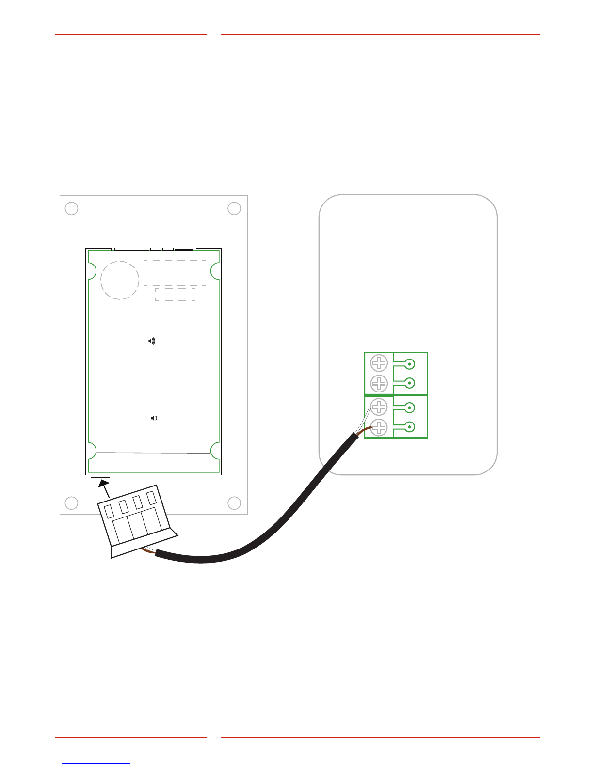
If extra voice station is connected, connection cable *CABLE14 is
required.
Page 6
6
1
2
3
4 5 6
97 8
*
0
#
SafeLine MX3+
Speaker B
serial no.
hologram
sw ver.
www.safeline-group.com
Speaker A
MX3+ v.2. 02 EN
Overview
Wiring diagram,
H1/H2
Use CABLE15 to connect SafeLine
MX3+ with a hearing loop.
CABLE15
Hearing loop
Page 7
7
hologram
serial nr.
sw ver.
www.safeline-group.com
1
2
3
4
5
6
7
8
9
*
0
#
SafeLine MX3 +
MX3+ v.2. 02 EN
Overview
Wiring diagram,
output 1, 2 and
external button
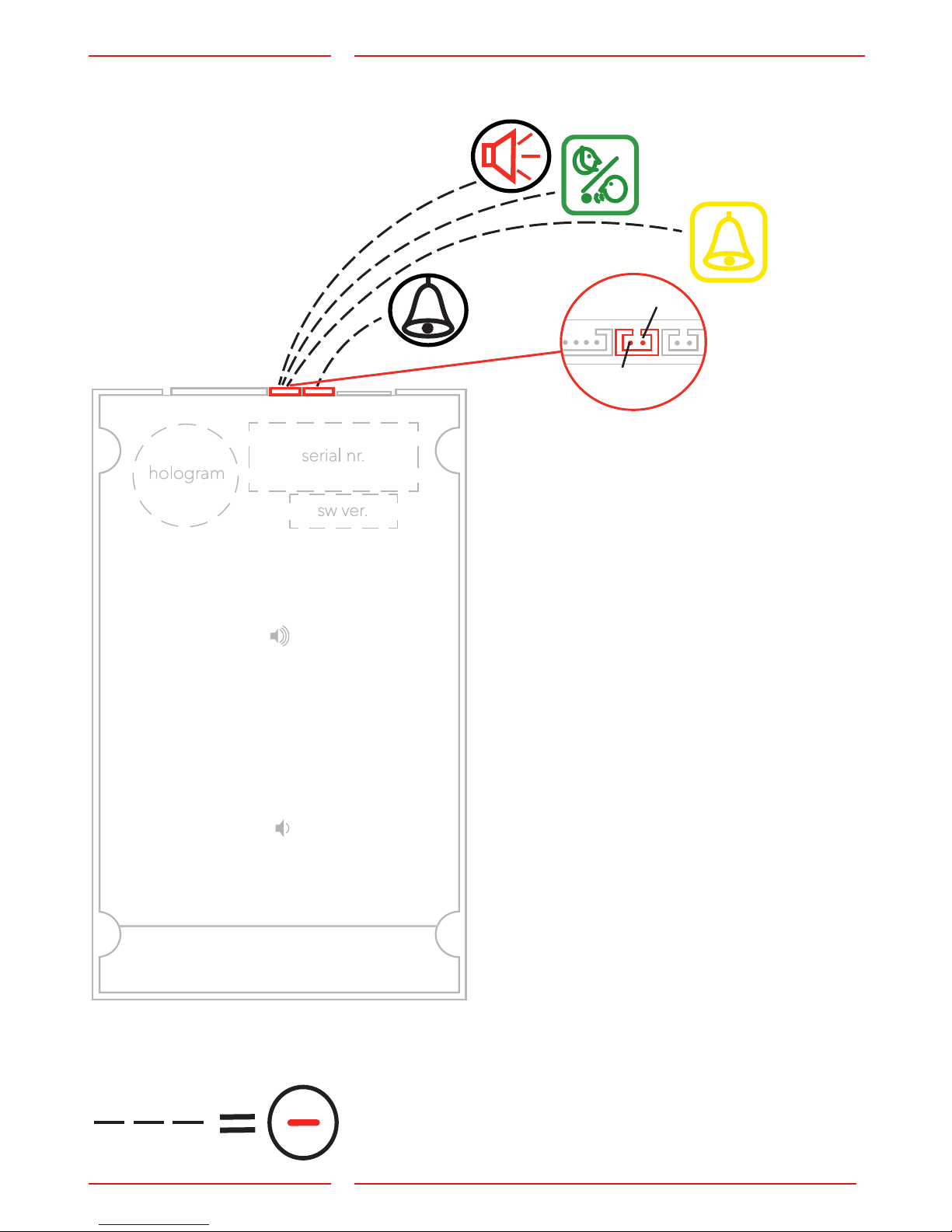
Use CABLE13 to connect SafeLine MX3+ with
external accessories. Output 1 and 2 can be
congured independently.
Requires that the output
is congured for the
corresponding function.
Please refer to the Parameter
list (*88*) or the app for
more information.
0 = Pictogram (Output 1 - yellow, Output 2 green)
1 = Activate with DTMF 8/9 (Output 1 - DTMF8,
Output 2 – DTMF9)
2 = System failure
3 = Emergency bell
E.g. *88*13# congures output 1 for an
emergency bell.
Pictogram yellow
(Output 1, Conguration code 0)
The output is activated at the following events:
- Input for emergency bell is activated.
- Input for emergency bell is set active at a certain time.
The output is deactivated at the following events:
- Distress input deactivated before set time.
- Active alarm ended.
- Reset button (#) is pressed.
Pictogram green
(Output 2, Conguration code 0)
The output is activated at the following events:
- Voice communication activated.
- Incoming call connected.
The output is deactivated at the following events:
- Outgoing call ended/timeout/cancelled.
- Incoming call ended/timeout/cancelled.
- Reset button (#) is pressed.
Outputs
The two outputs can be congured independently
with a number of functions. The conguration
is performed via SafeLine Pro or with the
conguration code *88*XY#, where X species
output 1 or 2 and Y species the function:
Output 2
Output 1
Page 8

8
MX3+ v.2. 02 EN
Overview
Outputs
Activate with DTMF 8
(Output 1, Conguration code 1)
The output is activated at the following events:
- DTMF tone 8 is received.
The output is deactivated at the following events:
- 3 seconds after activation.
Activate with DTMF 9
(Output 2, Conguration code 1)
The output is activated at the following events:
- DTMF tone 9 is received.
The output is deactivated at the following events:
- 3 seconds after activation.
System failure
(Output 1 & 2, Conguration code 2)
The output is activated at the following events:
- Telephone line OK.
The output is deactivated at the following events:
- Telephone line missing.
Emergency bell
(Output 1 & 2, Conguration code 3)
The output is activated at the following events:
- Emergency alarm button input active.
- The call is not yet connected.
The output is deactivated at the following events:
- Emergency alarm button input deactivated.
- The call is connected.
Silence disconnect
The function will automatically disconnect a call if no sound is
received from the alarm operator within a set time. Only works for
voice calls, not for P100/CPC/Q23.
The conguration is performed via SafeLine Pro or with the
conguration code *92*X#, where X species the time:
0 = The function is off.
1 = 30 seconds.
2 = 60 seconds (default).
3 = 90 seconds.
Volume control through software
The speaker volume is adjusted via the keyboard control. Key 2
raises and Key 8 lowers the volume in 6 steps. The volume can also
be adjusted using the command *76*X# where X is the desired
volume position between 1 and 6. Default value is 3.
The set volume mode are stored in the EEPROM so that the unit
remembers the set position.
External mic/voice station
When a call is activated by the emergency alarm button on
the external mic/voice station, the microphone on the external
mic/voice station will be used and the internal microphone
disconnected. The speaker sound will however be heard from both
speakers simultaneously.
Functions
Page 9
9
MX3+ v.2. 02 EN
Conguration
Android iPhone
Android
iPhone
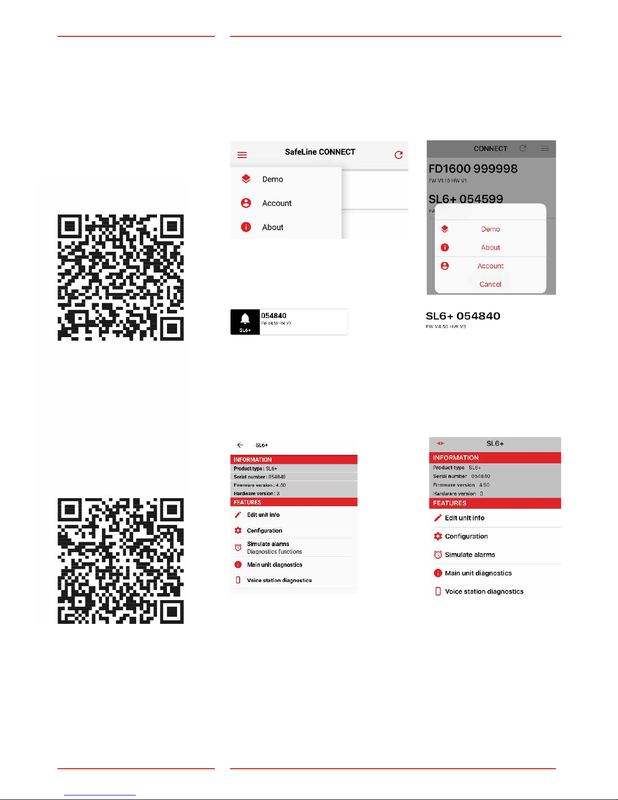
Press the SL6+ icon. To access a device it must have a programmed
password or have been restarted within 10 minutes. Every time the
device is powered on, the device’s bluetooth is open for 10 minutes, allowing you to program a password for the unit. Note: some
devices are quicker than other to nd the devices nearby. If the
device doesn’t appear on the screen, try waiting a bit longer.
When accessing a SL6+ you can see the device information at the top.
Android iPhone
You can then select:
Edit unit info
– This is the name and phone number of the device and how the
device is found.
Conguration:
– Here you congure all the functions for voice stations, in- and
outputs etc.
Simulate alarms:
– Here it is possible to simulate an alarm, battery failure, callback,
stuck button etc.
Main unit diagnostics:
– See current status of the device (for example: battery status, active
alarms, mains status, etc.)
Voice station diagnostics:
– Se current status of voice stations.
Congure
with Safeline
CONNECT
The SafeLine CONNECT app
is used to congure and
surveil your SafeLine devices.
Apple store, iPhone
Google play, Android
Download SafeLine CONNECT from Google Play or the Apple App
Store. To fully use the app’s features you must register an account.
In the upper corner you can access a menu containing account
information, patch notes and a demo mode. To register an account:
select account and then ”Register new account”. You will then be
redirected to a site where you register your product key.
Page 10
10
SafeLine SL6
SafeLine
ProLink
SafeLinePro
1 2 3
4 5 6
7
8 9
0
*
#
SafeLinePro
1 2 3
4 5 6
97 8
*
0
#
SafeLine MX3+
serial no.
hologram
sw ver.
www.safeline-group.com
MX3+ v.2. 02 EN
Conguration
Conguration
interfaces
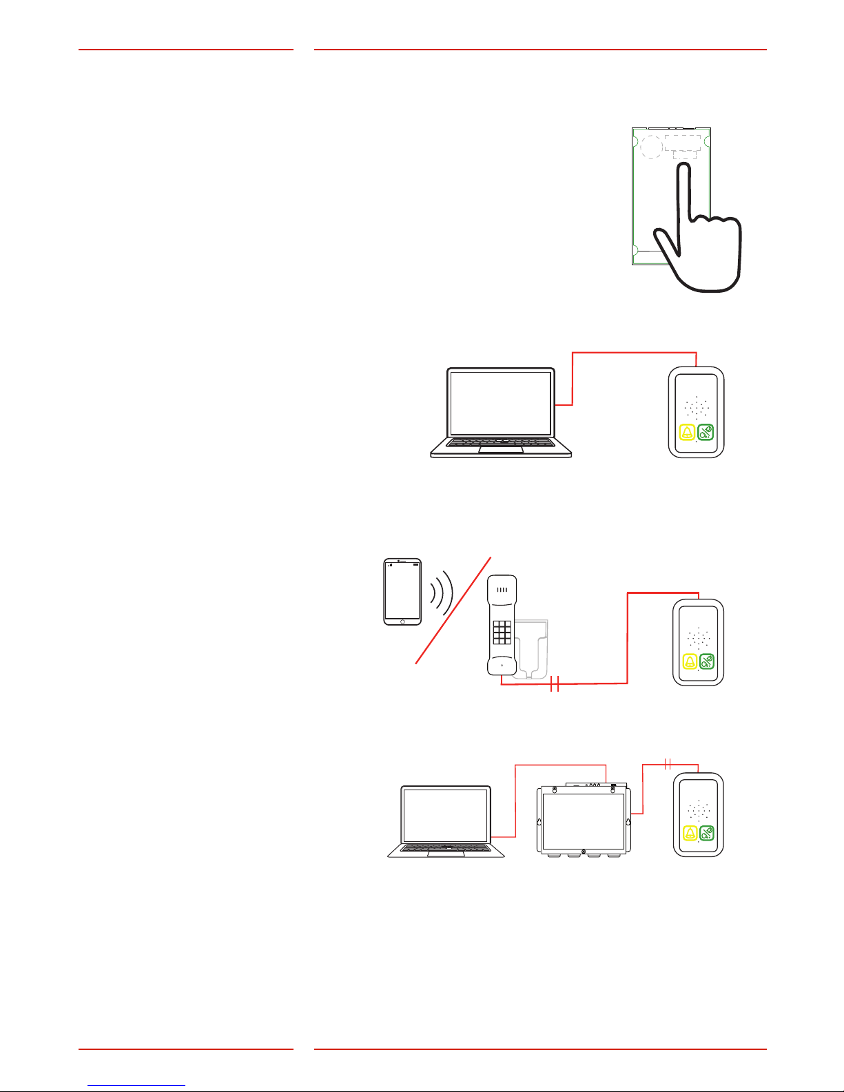
Keyboard conguration
The integrated keyboard at the rear of the MX3+ enables a fast
conguration of the unit.
Conguartion with SafeLine Pro
The unit can be congured at the ofce prior to the installation or at
site after installation, with a conguration cable (*PCable).
Remote conguration
For remote conguration, you can use any PSTN tone dial phone.
Please nd the instructions of how to perform it in the section
”Conguration method” (page 12).
Remote conguraion with SafeLine Pro
Connect an SLPro Link to a computer with SafeLine Pro and a serial cable.
The unit has to be connected
to a power source before the
conguration can begin.
SafeLine Pro can be downloaded on our website:
http://www.safeline-group.com/en/downloads/
SafeLine Pro 4.42 or later is required.
Page 11
11
MX3+ v.2. 02 EN
Conguration
Remote conguration
with external telephone.
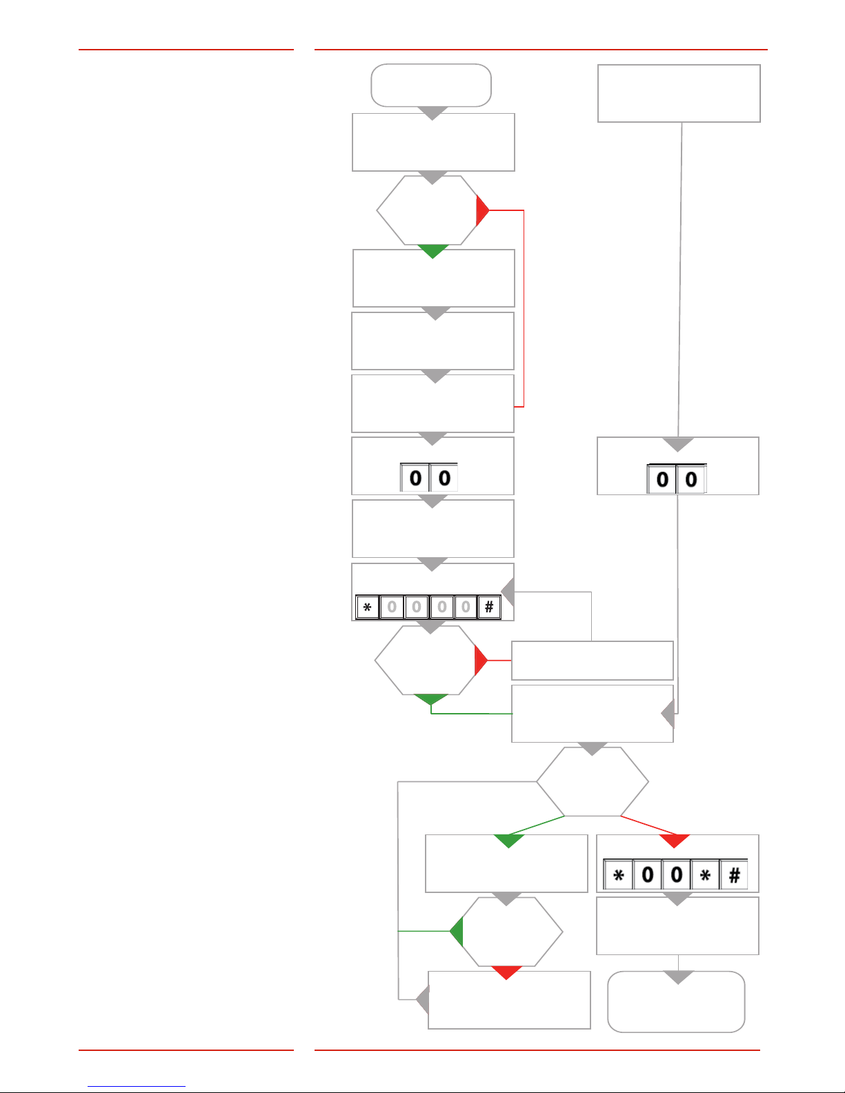
Conguration
with telephone
If the time between the
operation of two keys exceeds
10 seconds, the code has
to be re-entered. If the time
exceeds 30 seconds, the call is
disconnected or conguration
mode is ended.
Dial phone number.
Multiple units
connected to
phone line?
1 beep.
(All MX answers)
Press unit no. [ 1-9 ]
repeatedly.
(Until recieving 3 tones)
3 beeps.
(Requested unit answers)
Start conguration:
2 short beeps.
(Waiting for password)
Enter the password:
Valid
password?
Wrong password
(One long beep).
2 short beeps.
(Entering conguration mode)
Continue
conguration?
2 short beeps.
Call disconnected or
end of conguration.
MX3+ will restart with
the new settings.
Enter code,eg: *11*
Enter setting, eg: 012341234
End parameter: #
2 short beeps?
One long beep.
Invalid input. Last code
has to be re-entered.
On-site conguration
using the keyboard.
Start conguration:
Quit conguration:
Page 12
12
MX3+ v.2. 02 EN
Conguration
Conguration
examples
SafeLine emergency
telephones
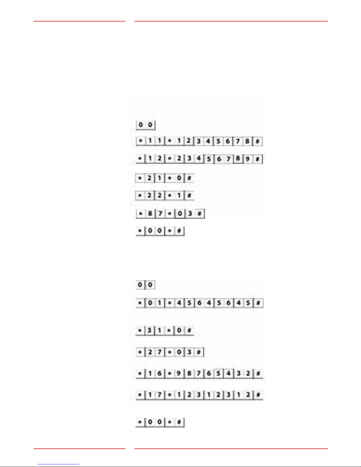
Example 1: Storing of two different telephone numbers, one
to be answered by P100 code
and the other one with voice.
For test facility, see example 2.
1.Start conguration:
2.1
st
phone number:
3.2
nd
phone number:
4.Call type 1
st
number:
5.Call type 2
st
number:
6.Alarm button delay:
7.End conguration:
- Example: Answered with P100 code.
- Example: Answered as voice call.
- Example: 3 seconds delay.
1.Start conguration:
5.LMS phone number:
4. Set number of days
between test alarm:
3.Set test alarm type:
Example 2: SLCC (SafeLine
Call Centre) and 3-day test.
If at any time you need to start over, use the factory reset
command *99*1#. Please refer to the full conguration setup in the
“Parameter list” as these are merely examples.
(Only if using SLCC)
(For more information, please refer to parameter *17* in the
”Parameter list”)
Lift ID code (each lift must have its own unique code).
- Example: 3 days between test alarm.
- Example: Test alarm type P100.
7.End conguration:
6.Test alarm:
2.Enter P100 ID code:
Page 13

13
MX3+ v.2. 02 EN
Conguration
Parameter list
CONFIGURATION
CODE DATA COMMENTS
Enter conguration mode
00
Enter password * - - - - # Default = 0000
Exit conguration mode *00*#
ALARM CODE DATA COMMENTS
P100 ID code *01* - - - - - - - - # P100 is always 8 digits
CPC ID code *02* - - - - - - # CPC 6-8 digits
Q23 ID code *03*
- - - - - - - - -- - #
Q23 is always 12 digits
TELEPHONE NUMBERS
CODE DATA COMMENTS
1st Phone number *11* - - - - - - - - - #
Phone number to alarm receiver: 1-20 digits.
If calling through a switch board, delay time
can be set by adding asterisks between
leading number of the switchboard and
telephone number for the alarm call receiver.
Each asterisk (*) is equal to one second delay.
Example #1: *11*0**1234567#
Example #2: *11*# deletes the phone number.
2nd Phone number *12*
- - - - - - - - - #
3rd Phone number *13* - - - - - - - - - #
4th Phone number *14*
- - - - - - - - - #
CALL TYPE
CODE DATA COMMENTS
Call type 1st number *21* - # Change the call type of the stored telephone
numbers:
0 = P100
1 = VOICE (default)
2 = Q23
3 = CPC
Change this only if your alarm operator is using
any of the mentioned protocols.
Call type 2nd number *22* - #
Call type 3rd number *23* - #
Call type 4th number *24* - #
Call type LMS number *30* - # LMS (Lift Monitoring System) call type:
0 = P100
3 = CPC (Only battery alarm)
Page 14

14
MX3+ v.2. 02 EN
Conguration
TEST ALARM
BATTERY ALARM
CODE DATA COMMENTS
LMS phone number *16* - - - - - - - - - # LMS (Lift Monitoring System) phone number to alarm
receiver or SLCC.
Test alarm *17* - - - - - - - - - # Phone number to test alarm receiver or SLCC.
Days between tests *27* - - # Number of days between test alarms, 00-99 days.
Always two digits.
Max 3 days according to EN 81-28.
00 = No test alarms
Test alarm protocol *31* - # 0 = P100
3 = CPC
4 = Caller ID
ALARM TYPE CODE DATA COMMENTS
Alarm type 1st number *41* - - #
Only when using CPC as alarm protocol
Normally 10 or 27, check with your alarm company!
Alarm type 2nd number *42* - - #
Alarm type 3rd number *43* - - #
Alarm type 4th number *44* - - #
Alarm type LMS *45* - - # LMS (Lift Monitoring System)
(Battery alarm)
Normally 17
Alarm type Test alarm *46* - - # Normally 26
DISTRESS MESSAGE CODE DATA COMMENTS
Record distress message
played in the lift car
*51* ”Speak” # This message will be played in the lift car when the
emergency lift telephone starts calling the alarm
centre. Make sure that there is no noise in the
background when recording the message.
Example of message:
Please do not panic, the emergency telephone is
now calling the emergency call centre.
Record alarm message
from Lift Car to alarm
central
*52* ”Speak” # This message will be played to the alarm receiver
and in the car when the call is answered. Make
sure that there is no nose in the background when
recording the message.
Example of message:
This is an alarm from the lift on 5th avenue.
To hear the quality of the message, press “1”.
To terminate the call press “#”.
Options for the recorded
distress message
*61*
*61*
- #
#
To play the recorded message, press the desired
parameter followed by #.
Options for the recorded
message from Lift Car
*62*
*62*
- #
#
0 = Disable recorded message.
1 = Enables recorded message.
Page 15

15
MX3+ v.2. 02 EN
Conguration
OTHER CODES CODE DATA COMMENTS
Emergency signal in
speaker
*71* - # The speaker siren will sound at emergency
call.
0 = Off (default)
1 = On
Ring-tone timeout *72* - - # Number of ring signals before dialling the
next number (default = 08).
Additional input
function
*73* - #
Selects input function:
0 = None (Default)
1 = Filter, blocks the alarm input when active.
2 = LMS (Lift Monitoring System), sends a lift
monitoring alarm at input activation.
3 = Clear/Maintenance
4 = Call Delay
Additional input type *74* - # 0 = Normally-open contact, N/O (Default)
1 = Normally-closed contact, N/C
Hotline *75* - # Phone connects directly to a xed receipient
without phone number
0 = Standard phone line (default)
1 = Hotline
Volume control *76* - # Adjustabel volume, between 1-6.
(Default = 4)
Page 16

16
MX3+ v.2. 02 EN
Conguration
OTHER CODES CODE DATA COMMENTS
Compatibility mode *77* - # 0 = Automatic voice switching
The call is validated when there is a voice
response.
The call is terminated by pressing ”#”.
1 = Kone ECII (lift telephone)
When there is a voice response, some
ascending tones will be heard.
The call is validated by pressing ”4”.
The call is terminated by pressing ”0”.
The call is terminated without reciept notication
by pressing ”2”(the unit will call the next number).
2 = Manual voice switching
When there is a voice response, some
ascending tones will be heard.
The call is validated by pressing ”4”. Unit is
still in automatic mode. ‘
To enter manual mode and talk press ”*”.
To listen press ”7”.
Go back to automatic mode press ”4”.
The call is terminated by pressing ”#”.
It is possible to enter manual voice switching
mode although the unit is programmed as
automatic by pressing ”*”. No ascending
tones will be heard.
For repeating the Alarm messages to
operator, press “1” in all in/out going calls.
3 = Swiss M (Alarm operator mode)
Only to be used in voice mode.
Disconnect by “0”.
Dials the next number if call timeout, blocking
tone, new dailing tone, and operator silence.
Indicator mode *78* - # 0 = Standard (default)
1 = Strictly EN81-28
2 = Strictly single EN81-28
Voice communication time-out
*79* - - # Value 1 - 20 minutes.
05 = default value
08 = default value for other protocols
Reset active alarm
automatically
*80* - # 0 = Off
1 = On (default)
Auto answer *81* - - # Number of signals before SafeLine answers
incoming call.
Can be set from 00-16 (default = 02).
00 = Never answering.
Unit number *82* - # Unit number [0] is set by default, and means
that the unit will respond immediately.
Unit number [1-9] is used when the units
are sharing the same phone line. When the
unit number is assigned, the specied unit is
accessible for conguration.
Page 17

17
MX3+ v.2. 02 EN
Conguration
OTHER CODES CODE DATA COMMENTS
Detect dial tone *83* - # 0 = Off
1 = On (default)
Set to off if SafeLine has problem to detect the
dial tone.
Receipt to alarm
receiver with P100
protocol
*84* - # Select which message(s) to send to the alarm
receiver at an alarm call.
0 = None (default)
1 = Start of alarm
2 = Start+end of alarm
Break on new alarm *86* - # Disconnects a call longer than 60 seconds at new
activation of the alarm button and calls the next
emergency call number.
0 = Off
1 = On (default)
Alarm button delay
time
*87* - - # Delay time from pressing the alarm button until
activating the alarm.
00-25 seconds. Default = 05
Outputs *88* - - # The rst digit species the output, i.e Output 1 or
Output 2.
The second digit species the function:
0 = Pictogram
(Output 1 - Yellow, Output 2 - Green)
1 = Activate with DTMF 8/9
(Output 1 - DTMF 8, Output 2 - DTMF 9)
2 = System failure
3 = Alarm
Example:
*88*11# - Output 1, Activate with DTMF 8
*88*23# - Output 2, Alarm
Alarm button type *89* - # 0 = Normally-open contact, N/O (Default)
1 = Normally-closed contact, N/C
Page 18

18
MX3+ v.2. 02 EN
Conguration
OTHER CODES CODE DATA COMMENTS
Microphone sensitivity *90* - # The sensitivity of the microphone can be reduced
in three levels.
0 = No reduction (default)
1 = 20 % Reduction
2 = 40 % Reduction
3 = 60 % Reduction
Change password *91* - - - - # Change password (default=0000).
Operator silence
disconnect
*92* - # Disconnects the call when the alarm operator
has been quiet for longer than the time set.
0 = Off (default)
1 = 30 sec
2 = 60 sec
3 = 90 sec
Simulate an alarm event *94* - # Triggers an alarm event after conguration is
terminated.
1 = Emergency call
2 = Test alarm
3 = Battery failure
4 = Microphone/Speaker failure
5 = Receipt on voice call
6 = Maintenance
7 = Main unit power failure
8 = Stuck button alarm
Reset to default settings *99* - # 1 = Factory standard
2 = Default P100 (The following codes will be set):
*21*0#, *22*0#, * 27*03#, *76*4#, *80*1#,
*84*1#, *88*1#
3 = Default CPC (The following codes will be set):
*21*3#, *22*3#, *27*03#,
*76*4#,
*80*1#,
*84*1#, *88*1#
4 = Default VOICE (The following codes will
be set):
*21*1#, *22*1#, *27*03#, *
*76*4#,
80*1#,
*84*1#, *88*1#
Page 19
19
MX3+ v.2. 02 EN
Operating
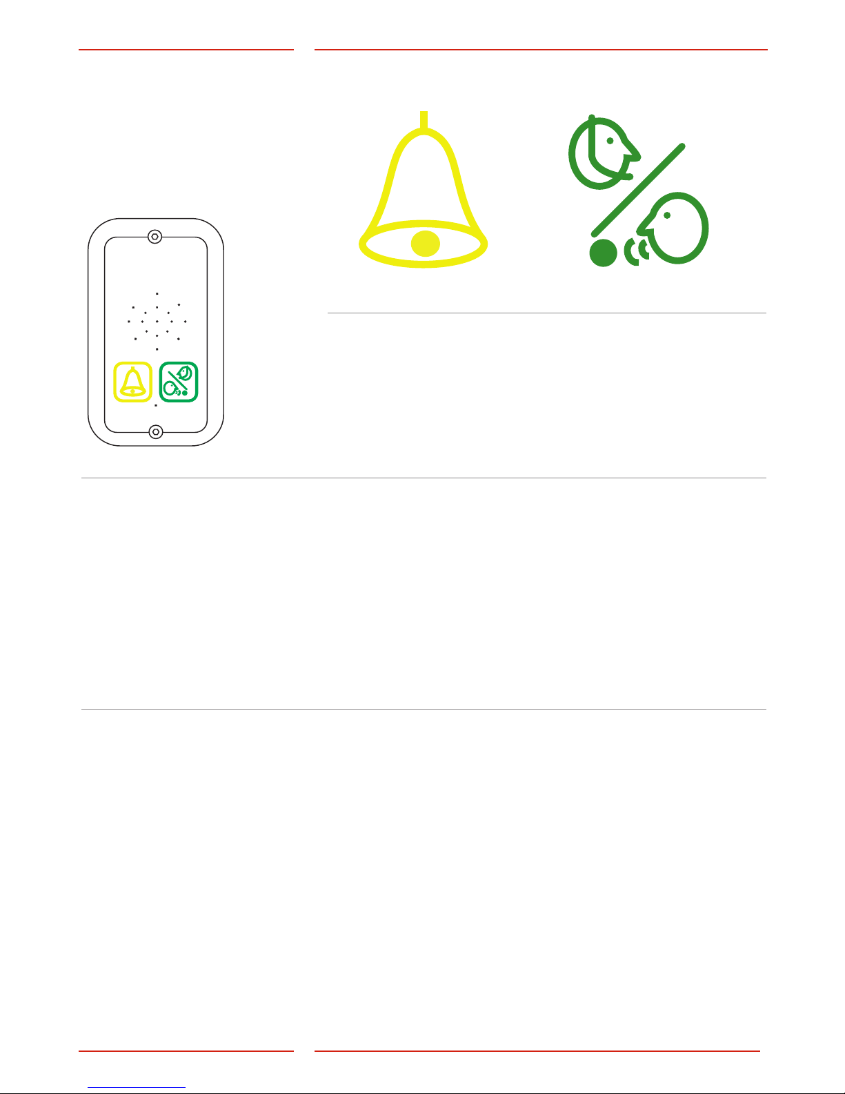
LED indication
for pictogram
in car
Yellow LED Green LED
Call in progress
The yellow pic togram LED is lit
as soon as the alarm button is
pressed.
Call connected
The green pictogram LED turns
on as soon as the SafeLine unit
detects a responding voice.
The LED is turned off when the
call is terminated.
Standard (*78*0#) Yellow LED Green LED
Light off No alarm activated Telephone line not OK.
Flashing slowly Fla shing once ever y 5 se co nds
Telephone line not OK.
Fla shing once ever y 5 se co nds
Unit is OK.
Flashing quickly Fla shing twice ever y secon d
Alarm button active.
Fla shing two times every 5
seconds
Alarm lter activated.
Continuous light Activated alarm. Remains lit
until reset.
Call connected.
St rict ly EN81-28 (*78*1#) Yellow LED Green LED
Flashing Fla shing twice ever y secon d
Alarm button active.
Continuous light Activated alarm. Remains lit
until reset.
Call connected.
Page 20
20
MX3+ v.2. 02 EN
Operating
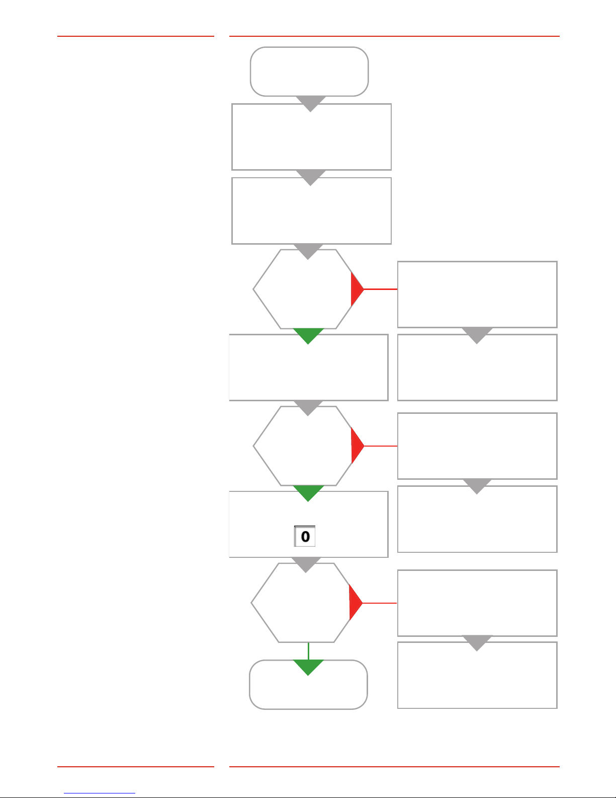
Testing
Testing the SafeLine
MX3+
Connect 10-30 VDC.
SafeLine MX3+ will make
a self-test.
Green LED ashes
5 times. Short tone
in the speaker?
Connect telephone line.
Green LED ashes
every 5 sec?
Press on keypad:
Phone line
dial tone?
Dial out on keypad.
Yellow LED ashes 5 times.
Long tone in the speaker.
Check the mic and speaker
connections.
Yellow LED ashes
every 5 sec.
Check telephone line.
No connection.
Check PSTN-line,
Go to Troubleshoot tables.
Page 21
21
MX3+ v.2. 02 EN
Operating
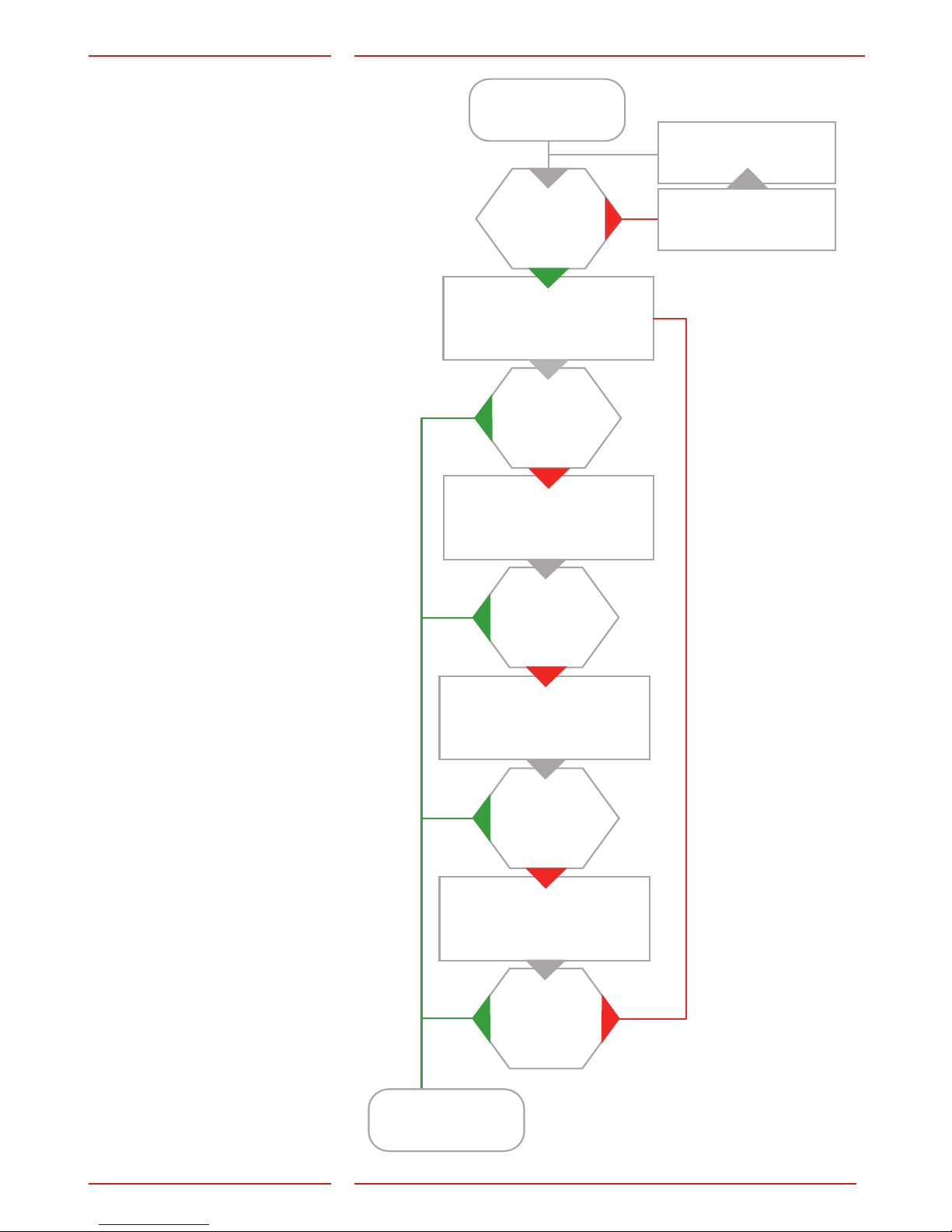
Emergency
calling process
Emergency alarm
activated.
Receiving tone?
Calling 1st phone
number.
Answer?
Calling 2nd phone
number.
Answer?
Calling 3rd phone
number.
Answer?
Calling 4th
phone number.
Answer?
Alarm operator
made connection.
Maximum 12 calls:
with 4 stored telephone
numbers, each number could
be called 3 times. This adds up
to the 12 call limit. To restart the
dialling process, another push
of the alarm button is needed.
Line missing or busy.
Wait 1 minute.
Page 22

22
MX3+ v.2. 02 EN
Operating
Troubleshooting
Emergency
button N/O
Emergency
button N/C
The telephone beeps every 5 seconds
This is to notify the passengers of the ongoing call (anti eaves
dropping).
The unit makes an alarm call when powered up
• Improper type of emergency button selected. Change from
N/C to N/O or from N/O to N/C.
• Emergency button is stuck.
No sound transmitted from the lift car to the call receiver
Press “0” to get an outside line. Make a call. If the sound
transmission is OK in both directions, check if your emergency
operator supports the chosen alarm type. If no protocol is used,
change the call type to “VOICE”. If no sound is transmitted from the
lift car, check the microphone.
Poor/distorted sound quality
Volume might be set too loud! Lower the volume and check again.
Interfering noise when the call is connected
The problem might be due to induction in the phone cable.
According to the phone companies’ regulations, the phone line
must be installed in a separate cable.
GSM noise
Change the antenna position when a call is connected until you
nd the optimal antenna position. Do not install the antenna near
the unit or close to the cabelling.
Cannot dial out
• Broken line connection (LED not blinking green).
• No money on rell SIM-card, verify the SIM-card by inserting it
into a normal mobile phone.
No voice switching
• The volume is set too high.
• The problem might be due to induction in the phone cable.
The unit can not make an alarm call
At least one phone number (and one ID code if using data
identication) must be congured to enable making a call from the
unit. Refer to the parameter list (*11*).
Page 23
Your partner in lift safety
Antennvägen 10, 13548 Tyresö, Sweden
+46 (0)8-447 79 32, www.safeline-group.com
EU Declaration of Conformity
Product: Lift telephone
Type / model: SafeLine MX3
Article no:
*SLMX3-COP, *SLMX3-COP2, *SLMX3-LENS90, *SLMX3-REC-PIC, *SLMX3-REC-PICB,
*SLMX3-SM-PIC, *SLMX3-SM-PICB, *SLMX3-SMD-PICB, *RU-SLMX30005
Manufacturer: SafeLine Sweden AB
Year: 2017
We herewith declare under our sole responsibility as manufacturer that the products referred to above
complies with the following EC Directives:
Directives
Radio Equipment (RED): 2014/53/EU
RoHS 2: 2011/65/EU
Standards applied
EN 81-20:2014 Lift: Safety & Technical requirements
EN 81-28:2003 Lift: Remote alarm on passenger and goods passenger lifts
EN 81-70:2003/A1:2004 Lift: Accessibility to lifts for persons including persons with disability
EN 12015:2014 EMC: Emission, Electromagnetic compatibility
EN 12016:2013 EMC/Lifts: Immunity, Electromagnetic compatibility
EN 62368–1:2014/AC:2015 LVD: Information Technology Equipment
EN 50581:2012 RoHS: Technical doc. for assessment of restriction of RoHS.
For RED 2014/53/EU, the conformity assessment procedure “Module A” used as described in Annex II. Accordingly, respective manufacturer
has done the radio modules conformity assessment:
Standards applied Article of Directive 2014/53/EU
EN 60950-1:2006+A11:2009+A1:2010+A12:2011 3.1 (a): Health and safety of the user
EN 62311:2008
EN 301 489-1 v2.1.1 + EN 301 489-52v1.1.0 Draft 3.1 (B): Electromagnetic Compatibility
EN 301 489-17 V3.1.1
EN 300 328 V2.1.1 3.2: Effective use of spectrum allocated
Firmware used during assessment
SafeLine MX3: 1.00
Tyresö, 2017-04-07
Lars Gustafsson,
Technical Manager, R&D , SafeLine Group
Module
Notified body
Address
NB nr
Test nr
CYW20732S
NTS Silicon Valley
41039 Boyce Road, Fremont, CA 94538, US
0214.26
R 104750/51
Page 24

www.safeline-group.com
SafeLine Europe
Industrieterrein 1-8 · 3290 Diest · Belgium
Tel.: +32 (0)13 664 662 · [email protected]
Support: +32 (0)4 85 89 08 95
SafeLine Deutschland GmbH
Kurzgewannstraße 3 · D-68526 Ladenburg · Germany
Tel.: +49 (0) 6203 - 840 60 03 · [email protected]
SafeLine Norway
Solbråveien 49 · 1383 Asker · Norway
Tel.: +47 94 14 14 49 · [email protected]
SafeLine Denmark
Erhvervsvej 19 · 2600 Glostrup · Denmark
Tel.: +45 44 91 32 72 · [email protected]
SafeLine Headquarters
Antennvägen 10 · 135 48 Tyresö · Sweden
Tel.: +46 (0)8 447 79 32 · [email protected]
Support: +46 (0)8 448 73 90
SafeLine Group UK
Unit 47 · Acorn Industrial Park · Crayford ·
Kent · DA1 4AL · United Kingdom
[email protected]
 Loading...