


SafeGait™ 360° Balance and Mobility Trainer
Service manual
SG360-ISM-004 Rev. F

SG360-ISM-004 | REV F
1
Table of Contents
General Warnings …………….……………………….……..………………………………………………………………………………..2
Load Cell Recalibration ................................................................................................................................. 3
Logging out of the SafeGait application kiosk .......................................................................................... 3
VNC service interface .............................................................................................................................. 4
Selecting load cell .................................................................................................................................... 8
HMI battery change procedure ................................................................................................................. 10
Opening the SafeGait covers ................................................................................................................. 11
Procedure for battery change .............................................................................................................. 13
Replace Trolley Wheel Block Assembly .................................................................................................... 14
Replace Strap Assembly ............................................................................................................................ 15
Setting Rotary limit switch ..................................................................................................................... 24
Actuator Check out Test ............................................................................................................................ 26
SafeGait Wiring Diagrams ......................................................................................................................... 27
Facility Panel Wiring Diagrams ................................................................................................................. 42
WIFI Ping Test ............................................................................................................................................ 47
Power Panel Green LED Replacement ...................................................................................................... 49
Version 4.0.1 Software install ................................................................................................................... 51
Data backup ............................................................................................................................................ 52
CF Card update to Version 3.1.1 ............................................................................................................. 53
Kiosk Laptop/Tablet (V4.0.1) Windows 10 .............................................................................................. 56
Kiosk Laptop/Tablet (V4.0.1) Windows 8 ................................................................................................ 62
Remote/Handheld Android 5.1 ............................................................................................................... 68
Remote/Handheld Android 6.1 ............................................................................................................... 69
Router upgrade ....................................................................................................................................... 70
WIFI adaptor upgrade ............................................................................................................................. 73
NAS upgrade ........................................................................................................................................... 75
Linear Bearing Replacement ..................................................................................................................... 78
4 Pole hanger replacement ...................................................................................................................... 82
Conductor shoe replacement .................................................................................................................. 83

SG360-ISM-004 | REV F
2
General Warnings:
WARNING: Arc flash is possible
during power-up after service if the
conductor shoes are not installed in
the correct conductor bars.
DANGER: the SafeGait 360® system
operates at 480 VOLTS. Always use
caution and wear appropriate PPE
(Personal Protective Equipment)
when working near Actuator or Rail
when power is applied. Failure to
comply may result in injury or
death!
WARNING: Pinch points areas
include the trolley wheels on the
rail and the Actuator end stops (if
installed).
WARNING: when servicing the
Actuator after operation, the
horizontal and vertical drive motors
may be hot.

SG360-ISM-004 | REV F
3
Load Cell Recalibration:
1. From the kiosk computer, exit out of the SafeGait Application by pressing (Ctrl +Shift +Esc).
This will a launch the Task Manager
2. Click on the file menu and select Run new task.
3. In the Create new task window in the open box type explorer.exe and press ok.

SG360-ISM-004 | REV F
4
4. Depress the windows key. This will launch the blue widow start screen at the top. Click on the
therapist user and a pop up window will appear. Select Admin user.
5. Enter admin password for kiosk. Reference KeePass for site specific password.
6. Open VNC viewer on desktop.
7. Connect to the service interface using VNC at IP address 10.0.0.2:5900.
10.0.0.2:5900

SG360-ISM-004 | REV F
5
8. When prompted for a password enter 123.
9. Log in using Service Code 8 followed by the check key.

SG360-ISM-004 | REV F
6
10. Click on the FACTORY PAGE button.
11. To calibrate the load cell, click on the LOAD CELL CALIBRATION button.

SG360-ISM-004 | REV F
7
12. Remove the spreader bar from the strap such that no weight is suspended.
13. Press the Calibrate Bias button in the VERTICAL axis (left side). The vertical Bias number should
change to the Load (Raw) value and the load (in lbs) should be 0 (zero).
14. Re-attach the spreader bar and let it hang. Wait for any swinging to cease.
15. Press the Calibrate Bias button in the HORIZONTAL axis (right side). The horizontal Bias number
should change to the Load (Raw) value and the load (in lbs) should be 0 (zero)

SG360-ISM-004 | REV F
8
16. When the recalibration is complete, the vertical load cell should display a load of 1-2 lbs. and the
horizontal load cell should display a load of zero. Press the HOME PAGE button to complete the
recalibration.
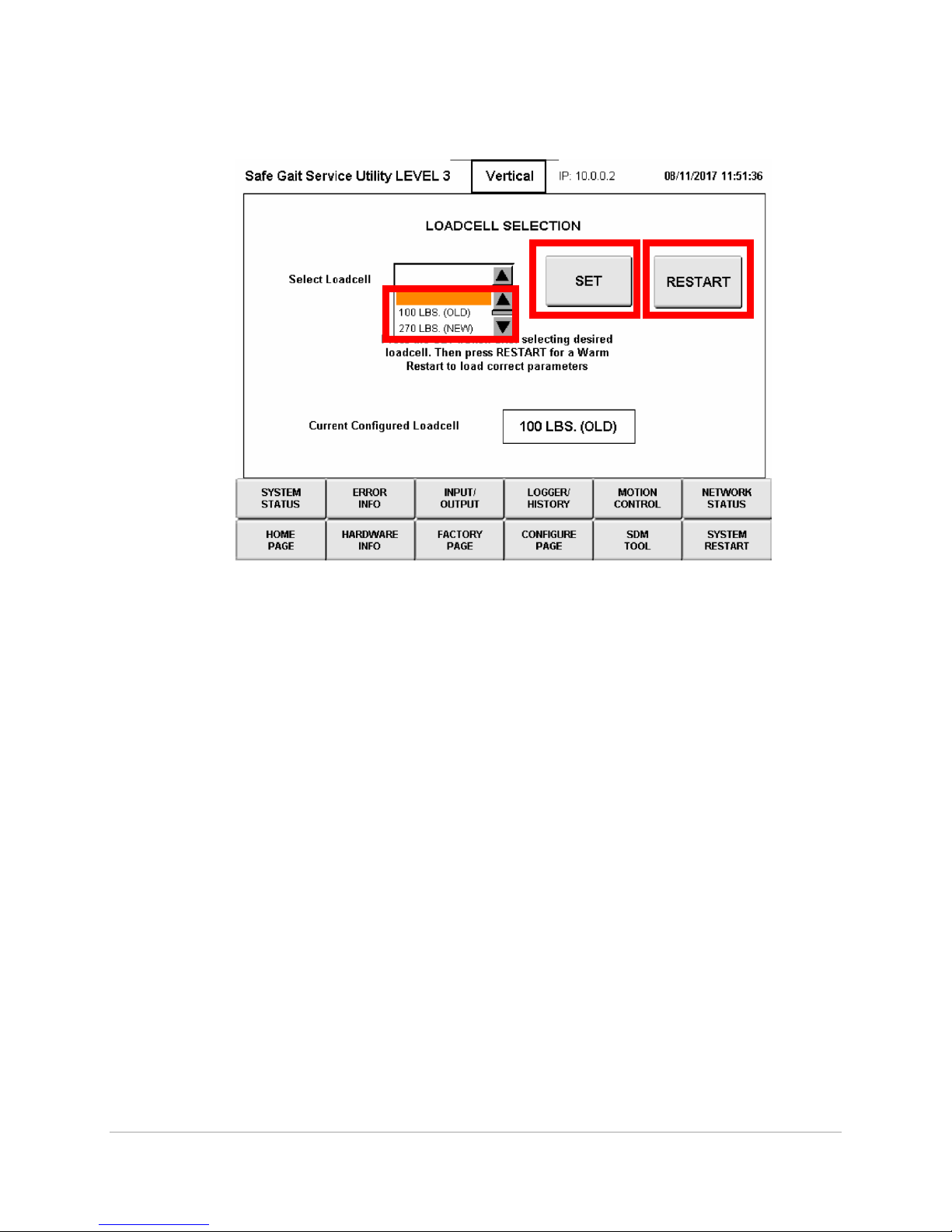
Selecting load cell
1. Login to VNC
2. Click on Factory page
SG360-ISM-004 | REV F
9
3. Click on the load cell selection Button
4. From select load cell drop down select the load cell that is in the strap management
5. Then press the set button
6. Followed by the reset button
7. Wait for the warm reset to occur then you can login to the VNC and verify the correct load cell
has been selected

SG360-ISM-004 | REV F
10
HMI battery change procedure:
The lithium battery buffers the internal real-time clock (RTC) and CMOS data.
Information:
• The product design allows the battery to be changed with the B&R device switched either
on or off. In some countries, safety regulations do not allow batteries to be changed
while the module is switched on.
• Any BIOS settings that have been made will remain when the battery is changed with the
power turned off (stored in nonvolatile EEPROM). The date and time must be reset later
since this data is lost when the battery is changed.
• The battery should only be replaced by qualified personnel
Warning!
The battery is only permitted to be replaced by a Renata CR2477N battery. The use of
another battery may present a risk of fire or explosion.
The battery may explode if handled improperly. Do not recharge, disassemble or
dispose of in fire.

SG360-ISM-004 | REV F
11
Opening the Covers:
1. Power down the unit and follow all lockout tag out procedures.
2. Using an insulated screwdriver, depress latching tab on inside of covers.
DANGER: Power system down and lock out power panel prior to opening the covers.
Failure to comply may result in injury or death!

SG360-ISM-004 | REV F
12
3. While holding in on latching tab press up on covers to release.
4. Disengaged the latching pins in on either side of the HMI allow HMI to swing down.
Note: starting with Actuator serial number 9101200C-0001, the latching pins are obsolete. Loosen
and remove the lower screw and nut on both sides of the bracket to allow the HMI to swing down.
5. Locate battery on backside of HMI.

SG360-ISM-004 | REV F
13
Battery Replacement Procedure
The battery should not be held by its edges. Insulated tweezers may also be used to insert the
battery
• To make the next battery replacement easier, be sure the removal strip is in place when inserting the
battery.
Correct
Incorrect
Disconnect the power supply to the B&R Industrial PC.
Touch the housing or ground connection in order to discharge any electrostatic charge from your body.
Remove the cover from the battery compartment and carefully pull out the battery using the removal strip.
Battery cover
Removal strip
Figure 162: Removing the battery

SG360-ISM-004 | REV F
14
Replace Trolley Wheel Block Assembly:
DANGER: Power system down and lock out power panel prior to replacing Trolley Wheel Block
Assembly. Failure to comply may result in injury or death!

SG360-ISM-004 | REV F
15
Replace Strap Assembly:
1. Login to the windows Admin using the provided password.
2. On the desktop open VNC
3. In VNC server line enter 10.0.0.2 if not already displayed in box then click connect
4. If a warning pops up about unencrypted connection click on the continue button if not skip to
step 5

SG360-ISM-004 | REV F
16
5. When prompted for a password enter 123
6. Login screen will pop up click on the service code and a keyboard will pop up.

SG360-ISM-004 | REV F
17
7. Click on service code box enter service code 8 followed by the check mark.
8. Then hit the enter key to login to the HMI

SG360-ISM-004 | REV F
18
9. On the login screen click on the input/output button
10. On the input/output page push the force button and then turn E-stop 1 and E-stop 2 Back on.
11. Then hit the Force button once again

SG360-ISM-004 | REV F
19
12. Click on the Motion control button and then enable the vertical motor
13. Using the Velocity NEG to pay out all of the strap from the unit using VNC client.
a. NOTE: When the spreader bar touches the floor, you will need to apply pressure to strap
to insure it continues to spool off the drum.
b. Use a pair of scissors to cut the strap as close as possible to the Actuator cover. Discard.
14. Power unit down and lock out tag out power panel.
15. Open covers using instructions listed in this manual.
16. NOTE: If installing a STRAP ASSEMBLY with a serial number of 0917001 or higher, removal and
replacement of the Strap Management Assembly is not necessary. Skip to step 22.
17. NOTE: starting with Actuator serial number 9101200C-0001, unplug the load cells from the
extension cables located on the vertical bracket.
18. Unplug load cells from signal conditioning PCB
a. You can remove the side cover to allow more access to the connectors

SG360-ISM-004 | REV F
20
19. Remove electrical connections from the slack limit switch.
20. Using a M3 hex key loosen the three bolts in strap management
a. Note only turn bolts one or two turns or small springs and bolts will fall loose from strap
management unit
b. For access to bolt on front of strap management remove black plastic cap on outside of
unit. Use a 12 inch ¼” extension to reach bolt.

SG360-ISM-004 | REV F
21
21. Push strap management away from the drum and slide it down the strap out of the unit. Place
the unit on a work surface.
22. Remove Drum cover from drum by pulling screws using the 2.5mm Hex Bit.
23. Slide drum cover plate on to flex coupling. Pull strap and strap pin from drum. Remove the
remaining strap and pin from unit and discard.

SG360-ISM-004 | REV F
22
24. Remove the four screws that secure the Cover-Slack Detector Guide to the assembly.
25. Remove four screws from roller arm and three screws from guide roller. NOTE: Not required if
installing a STRAP ASSEMBLY with a serial number of 0917001 or higher.
26. Take the STRAP ASSEMBLY and uncoil the small pin loop end. Use a tape measure to place a
reference mark at 39 ½ inches from the pin loop end to indicate the two revolution point for
future Rotary Limit Switch set-up. Thread through the Strap Management Assembly per the
illustration below. If necessary, use a flexible plastic shim to help thread the strap assembly
through the rollers. Note: Loop should be facing down. Pull the strap through until the reference
mark is 3-4 inches above the strap guide. Install PIN, STRAP ATTACHMENT into the small loop on
the end of the strap. Re-install the Cover- Slack Detector Guide, tightening the screws securely.
NOTE: insure correct side of cover is facing up. Re-install the roller arm and guide roller,
tightening screws securely. NOTE: Not required if installing a STRAP ASSEMBLY with a serial
number of 0917001 or higher. When properly tightened, mark each removed screw with a
paint pen.

SG360-ISM-004 | REV F
23
27. Check the actuation of the slack limit switch. Apply tension to both ends of the strap and listen
for the switch actuation. If the switch does not actuate, adjust its position and reevaluate.
28. NOTE: Steps 28 and 29 are not required if installing a STRAP ASSEMBLY with a serial number
of 0917001 or higher. Install the Strap Management Assembly on the Chassis Plate by inserting
the three posts into the keyhole slots and sliding towards the drum. Secure the posts in the
Chassis Plate by tightening the (3) set screws to 53 in-lbs using the torque wrench with the 3mm
Hex Bit. Two screws are accessible through the opening in the Fuse Panel and the third screw is
accessible from under the Drum. When properly tightened, mark each screw hole with a paint
pen.
29. Install the Horizontal and Vertical Load Cell connectors to the matching positions on the Signal
Conditioning PCB or the load cell extension cables (Actuator serial number 9101200C-001 or
higher)
30. Take the Pin end of the Strap Assembly and create two drum wraps per the illustration below.
Slide over the drum, while inserting the pin into the drum slot. NOTE: pull firmly on the strap
near the pin to verify it is seated in the drum slot. Re-install the flange, and tighten screws
securely using the 2.5mm Hex Bit. When properly tightened, mark each screw with a paint pen.

SG360-ISM-004 | REV F
24
31. Remove the lock from the power panel and power up the Actuator.
32. Strap Rotary Limit Switch check and adjustment: In the "Motion Control" screen on VNC, disable
Horizontal Motion and enable Vertical Motion.
33. Click and hold the vertical "MANUAL POS" button to drive the vertical drive motor in the positive
direction to rotate the drum approximately 1 revolution. Click and hold the vertical "MANUAL
NEG" button to drive the motor in the negative direction until the switch actuates. NOTE: keep
tension on the strap when rotating in the negative direction to actuate the slack limit switch.
Check the strap reference mark for 3-4 inches above strap management cover plate. If incorrect,
readjust down limit switch and recheck.
34. Perform the following steps if the switch requires adjustment.
35. Remove the Rotary Limit Switch cover and loosen the locking screw on top cam one full
revolution. Set the strap down limit switch by rotating the down limit cam (screw #2) counterclockwise until the lobe is starting to actuate the switch. Listen for the click.
36. To verify the adjustment, click and hold the vertical "MANUAL POS" button to drive the vertical
drive motor in the positive direction to rotate the drum approximately 1 revolution. Click and hold
the vertical "MANUAL NEG" button to drive the motor in the negative direction until the switch
actuates. NOTE: keep tension on the strap when rotating in the negative direction to actuate the
slack limit switch. Check the strap mark for 3-4 inches above strap management cover plate. If
incorrect, continue to readjust and recheck the down limit switch until set correctly.
37. If an adjustment was made, perform a cold re-start using the service interface (system restart ->
Restart type = cold restart -> restart button). Wait for the Actuator LED light to display solid white.
Login to service interface and navigate back to the motion control screen.
38. Click and hold the vertical "MANUAL POS" button to drive the vertical drive motor in the positive
direction to continue winding the strap on the drum until the switch actuates. The edge of
stitched flap on the strap should be 3 ±0.5 inches above the strap management cover plate.
Manually stop the winding if the buckle is less than 2 inches. If the setting is incorrect, readjust
the up limit switch and recheck.
39. Perform the following steps if the switch requires adjustment.
40. If not previously required, remove the Rotary Limit Switch cover and loosen the locking screw on
top cam one full revolution, set the strap up limit switch by rotating the up limit cam (screw #1)
clockwise until the lobe is starting to actuate the switch. Listen for the switch to click.
DANGER: Adjusting the Strap Rotary Limit Switch requires working on the Actuator
with power applied. Use a protective safety cover over live components or wear
appropriate PPE (Personal Protective Equipment) when making adjustments. Failure
to comply may result in injury or death!

SG360-ISM-004 | REV F
25
41. To verify the adjustment, click and hold the vertical "MANUAL NEG" button to drive the vertical
drive motor in the negative direction to rotate the drum approximately 1 revolution. NOTE: keep
tension on the strap when rotating in the negative direction to actuate the slack limit switch. Click
and hold the vertical "MANUAL POS" button to drive the motor in the positive direction until the
switch actuates. The edge of stitched flap on the strap should be 3 ±0.5 inches above the strap
management cover plate. If incorrect, continue to readjust and recheck the up limit switch until
set correctly.
42. When complete, tighten cam locking screw and mark with the paint pen. Reinstall the Rotary Limit
Switch cover. Remove the safety cover (if installed) and close the mechanical cover.

SG360-ISM-004 | REV F
26
Actuator Check Out Test:
A. Run power panel cycle:
Check each phase feeding power panel
Turn on
Press the reset; insure power on button lights up
Press the power off button
Insure power drops to the unit
Press the power on
Insure power has been returned to the unit
Depress the e-stop
Insure all power has dropped to unit
Reset e-stop
Reset panel
Power unit back on.
B. Power on the router and kiosk:
Check to make sure the router is connected to the tablet
Walk the length of the rail with the kiosk and insure signal does not drop off
Insure that actuator is connected to router
C. Cycle the unit using the hand-held kiosk:
Jog the unit the length of the track to insure there is no binding
If end stops are installed insure that unit stops at end stops
Cycle strap all the way out and make sure the white up limit measurement mark is
visible outside of the units cover
Cycle strap all the way up and make sure approximately 3 inches of strap is hanging
out of the unit
Record amp draw on vertical motor
L1______L2_____L3______
D. Attach spreader bar
Run unit in float mode to both ends of the track
Record amp draws on horizontal motor
L1______L2_____L3______
Technician’s name______________________
Signature __________________________
Date_____________________

SG360-ISM-004 | REV F
27
SafeGait Wiring Diagrams:
AC Power ................................................................................................................................................... 28
DC Power ................................................................................................................................................... 29
DC Power Continued .................................................................................................................................. 30
Vertical Drive Power .................................................................................................................................. 31
Horizontal Drive Power ............................................................................................................................. 32
Controls Power ........................................................................................................................................... 33
Control Communication ............................................................................................................................ 34
Status Light Control .................................................................................................................................. 35
Vertical Drive Control ................................................................................................................................. 36
Strap Vertical Limit ..................................................................................................................................... 37
Horizontal Drive Control ........................................................................................................................... 38
Horizontal Limit ......................................................................................................................................... 39
X87 Controller ........................................................................................................................................... 40
WIFI Adaptor ............................................................................................................................................. 41

SG360-ISM-004 | REV F
28

SG360-ISM-004 | REV F
29

SG360-ISM-004 | REV F
30

SG360-ISM-004 | REV F
31

SG360-ISM-004 | REV F
32

SG360-ISM-004 | REV F
33

SG360-ISM-004 | REV F
34

SG360-ISM-004 | REV F
35

SG360-ISM-004 | REV F
36

SG360-ISM-004 | REV F
37

SG360-ISM-004 | REV F
38

SG360-ISM-004 | REV F
39

SG360-ISM-004 | REV F
40

SG360-ISM-004 | REV F
41

SG360-ISM-004 | REV F
42
Facility Panel Wiring Diagram:
Primary AC Power ...................................................................................................................................... 43
Power ON ................................................................................................................................................... 44
E-Stop .......................................................................................................................................................... 45
Bus Power Monitoring .............................................................................................................................. 46

SG360-ISM-004 | REV F
43

SG360-ISM-004 | REV F
44

SG360-ISM-004 | REV F
45

SG360-ISM-004 | REV F
46

SG360-ISM-004 | REV F
47
WIFI Ping Test:
1. Press the Windows key on the key board to Launch the file explorer.
2. Type in CMD to the search field to launch an new command prompt

SG360-ISM-004 | REV F
48
3. In Command prompt type ping followed by the IP address you wish to ping followed by
–t
4. This will continues ping the IP address you have chosen.
5. 10.0.0.1 for the router.
6. 10.0.0.2 for the WIFI Adaptor.
7. 10.0.0.52 for the Actuator.
8. 10.0.0.4 for the handheld
9. To stop the ping, press Ctrl C.

SG360-ISM-004 | REV F
49
Power Panel Green LED light replacement:
1. Power down panel and lock out tag out power panel source
2. Open panel door
3. Locate back of power on button on panel door
4. Remove contactors on both sides of the power on button by placing a small flat head
screw driver on top of contactor and lifting up contactor will slide up and out
5. From green light LED remove wire 1431 from top of led and 110n from bottom
DANGER: Power system down and lock out power panel prior to opening the
panel door. Failure to comply may result in injury or death!

SG360-ISM-004 | REV F
50
6. With a small flat head screwdriver pry up on the plastic tab on the top of the LED light
will slide back and up
7. Replace led rewire and reconnected contactors to the back side of the button

SG360-ISM-004 | REV F
51
Version 4.0.1 Install instructions:
1. Instructions:
The purpose of this checklist is to verify that all necessary software components have been installed on
each hardware component of the SafeGait 360 Balance and Mobility Trainer. This ensures that the
system as a whole can run as anticipated.
Required:
Service Laptop with Android SDK installed.
USB stick with all necessary update files:
- Actuator Installation Package V3.1.0
- Kiosk UI software installer SafeGaitInstaller-4.0.1.msi
- Handheld UI software installer SafeGait-Debug.apk (version 4.0.1)
KeePass file for all passwords associated with the updated system
Ethernet cable
Compact Flash Card reader (if necessary for optional install procedure), OR
Compact Flash card pre-installed with latest version of actuator software.

SG360-ISM-004 | REV F
52
2. Database backup before update
IMPORTANT: The patient information database should be backed up prior to any software update.
□ Power on the Kiosk and log in as the admin user (using associated KeePass password).
□ Ensure that the NAS is booted up and connected to the router.
□ Using Windows Explorer, navigate to C:\SafeGait\Scripts\Backup (or C:\Temp\Scripts\Backup)
and Shift+Right Click on “Backup_Launcher.bat”. Choose “Run as different user” option and
enter username and password for backup user (located in KeePass).
□ Verify that a backup file has been created in C:\Gorbel Medical\SafeGait\Backup this file should
have the format SafeGait_YYYYMMDDHHMMSS.BAK.
□ Start Acronis Backup and select the SG Database Backup task. Right-click and select Run…
□ Check that backup completes successfully (warnings are OK, just dismiss them).
□ Make sure that an Acronis backup file has been exported to the NAS in the folder
\\SafeGait_NAS\Backup.

SG360-ISM-004 | REV F
53
3. Actuator (v3.1.1)
□ Lower Spreader bar to lowest possible position. (Lower limit)
□ From Kiosk or Tool Laptop on SafeGait network, open VnC and connect to the actuator (IP
address 10.0.0.2). Alternatively, open SafeGait cover to access HMI.
□ Log into Service Interface with service code 8
□ Navigate to the System Status Page (default)
□ Write down or take a picture of the ON time and RUN time for each axis:
Horizontal ON time
Horizontal RUN time
Vertical ON time
Vertical RUN time
□ Navigate to Factory Page Load Cell Calibration
□ Write down or take a picture of the load cell bias and load cell coefficient for both axes.
Horizontal BIAS
Horizontal COEF.
Vertical BIAS
Vertical COEF.
□ Exit the service interface by clicking/tapping on the HOME PAGE button.
□ Connect an Ethernet cable from the HMI to the to the tool laptop
□ Navigate to where you copied the Actuator Installation Package (V3.0.0)
Option 1:
□ Open folder Configuration Values
□ Run the script: Config_Param.bat (read calibration and run time values)
□ On the command prompt type R to read values
□ Let script run

SG360-ISM-004 | REV F
54
□ When read script finishes successfully close the window
□ Power off the actuator HMI and remove the compact flash card from it.
□ Replace CF with updated CF card or Preform the Create CF card steps
Create CF Card
□ Place the card in the compact flash card reader located in/with the tool laptop.
□ Run the script: Create_CF.bat. This will format the card and install the new software.
□ Alternatively, use a pre-programmed CF card with V3.0.0 already loaded.
□ Replace the card in the HMI, and power on the actuator.
Write CF card values
□ Open folder Configuration Values
□ Run the script: Config_Param.bat (read calibration and run time values)

SG360-ISM-004 | REV F
55
□ On the command prompt type W to write values
□ Let script run
□ When Write script finishes successfully close the window
□ ***copy the file update_vars.txt onto a USB stick for safekeeping.
□ Upon return, place the update_vars.txt into the customer-specific network location. (e.g.
S:\Quality System\RECORDS\Device History Records – SafeGait 360\Customers\XXXX\Service\Software
where XXXX is the customer number)

SG360-ISM-004 | REV F
56
4. Kiosk Laptop (V4.0.1) Windows 10
□ Turn the Kiosk on, and log into Windows using the administrator (admin) account.
□ Click on the Windows button () and type services.msc to launch Windows local services.
□ Search for SafeGait Admin Service and press Stop the service. Do not close the services window.
□ Click on the Windows button () and type Control Panel to access the control panel.

SG360-ISM-004 | REV F
57
□ Under Adjust your computer settings – Click on Administrative Tools
□ Under Administrative Tools – Click on Internet Information Services (IIS)
□ Click on the Windows button () and type Add or Remove Programs.

SG360-ISM-004 | REV F
58
□ Type app name SAFEGAIT 360 BALANCE AND MOBILITY TRAINER.

SG360-ISM-004 | REV F
59
□ Click on the uninstall button.
□ Click on the Uninstall button on the pop up message that appears.
□ Copy the latest Kiosk installer SafeGaitInstaller-4.0.1.msi to the disk and run it.
□ Navigate to C:\Gorbel Medical\SafeGait\webapi and edit the file Web.config. Under the
connectionStrings node, modify the SQL password to match the one in KeePass.

SG360-ISM-004 | REV F
60
□ Navigate to C:\Gorbel Medical\SafeGait\service and edit the file AdminService.exe.config.
Under the connectionStrings node, modify the SQL password to match the one in KeePass.
□ Navigate to C:\Gorbel Medical\SafeGait\bin and open an administrator command prompt.
□ Type install.bat and press Enter. When prompted for credentials, username = SAFEGAIT-PC,
password = Windows login password for the administrator (admin) account from Keepass. You
may get an error/warning message in the prompt window, but this is normal for updates.
□ Go back to the main IIS window and re-start the server.

SG360-ISM-004 | REV F
61
□ Verify the SafeGait WebApi has been installed properly by opening Chrome and navigating to
https://localhost/safegait using the kiosk laptop (the page should load without error).
□ Go back to the services window and re-start the SafeGait Admin Service
□ Check that the Windows system time and date are current.
□ Clear any unwanted icons off the desktop, start screen, etc. for the therapist user

SG360-ISM-004 | REV F
62
5. Kiosk (V4.0.1) Windows 8
□ Turn the Kiosk on, and log into Windows using the administrator (admin) account.
□ Click on the Windows button () and type services.msc to launch Windows local services.
□ Search for SafeGait Admin Service and press Stop the service. Do not close the services window.
□ Click on the Windows button () and type IIS to start Internet Information Service.

SG360-ISM-004 | REV F
63
□ Under Action – Manage Server click on Stop. Do not close the IIS window.
□ Go to the Windows Control Panel – Programs and Features.
□ Double-click on the SAFEGAIT 360 BALANCE AND MOBILITY TRAINER to remove it.
□ Copy the latest Kiosk installer SafeGaitInstaller-4.0.1.msi to the disk (anywhere) and run it.
□ Navigate to C:\Gorbel Medical\SafeGait\webapi and edit the file Web.config. Under the
connectionStrings node, modify the SQL password to match the one in KeePass.

SG360-ISM-004 | REV F
64
□ Navigate to C:\Gorbel Medical\SafeGait\service and edit the file AdminService.exe.config.
Under the connectionStrings node, modify the SQL password to match the one in KeePass.
□ Navigate to C:\Gorbel Medical\SafeGait\bin and open an administrator command prompt.
Type install.bat and press Enter. When prompted for credentials, username = SAFEGAIT-PC,
password = Windows login password for the administrator (admin) account from Keepass. You
may get an error/warning message in the prompt window, but this is normal for updates.
□ Go back to the main IIS window and re-start the server.
□ Verify the SafeGait WebApi has been installed properly by opening Chrome and navigating to
https://localhost/safegait using the kiosk laptop. The page should load as shown below – the
security error acceptable as long as this page loads.

SG360-ISM-004 | REV F
65
□ Go back to the services window and re-start the SafeGait Admin Service
□ Press the Windows key () and type Schedule Tasks in Windows. Launch Task Scheduler.
□ Under Microsoft Windows Windows Update, verify that all tasks are disabled. If they are
enabled, disable them.
□ Under Lenovo Verify that all Lenovo scheduled tasks are disabled. If they are enabled, disable
them.
□ Check that the Windows system time and date are current.

SG360-ISM-004 | REV F
66
□ Clear any unwanted icons off the desktop, start screen, etc. for the therapist user
**Permissions changes on Kiosk: Perform the next 7 steps to verify whether additional folder
restrictions are needed on the kiosk.
□ Login as Therapist user, wait for SafeGait application to load.
□ Press Alt-F4 to quit the application.
□ Press CRTL-Shift-Esc to bring up the Task Manager
□ Click on File…Run and type explorer.exe. Windows explorer should launch and you should see
the taskbar appear at the bottom of the screen.
□ Open windows explorer and navigate to the folder: C:\Gorbel Medical\SafeGait\Backup. Check
if user has access to this folder.
□ Navigate to the folder: C:\SafeGait\Scripts. Check if user has access to this folder. If this folder
does not exist, the scripts folder may also be located in C:\Temp\Scripts.
□ If therapist user does not have access to these folders, skip the rest of this section and proceed
to handheld installation (Section 5).
** If permissions changes are necessary:
□ Logout of Windows and log back in as Admin user.
□ Open windows explorer and navigate to the folder: C:\Gorbel Medical\SafeGait\.
□ Right-click on the Backup folder and select Properties…
□ Select the Security tab and click Advanced

SG360-ISM-004 | REV F
67
□ On the next screen, click Change Permissions…
□ Uncheck “Include inheritable permissions from this object’s parents”
□ On the pop-up dialog, click Add
□ Check “replace all child object permissions with inheritable permissions from this object”
□ Click Add…
□ On the next screen in the box type backup then click on Check Names. The backup user should
be underlined, then click on OK.
□ The backup user should be added to the list of folder permissions. Make sure this user has full
control.
□ Back on the Advanced Security Permissions tab, click Add… again.
□ On the next screen in the box type admin then click on Check Names. The admin user should be
underlined, then click on OK.
□ The admin user should be added to the list of folder permissions. Make sure this user has full
control.
□ Click on Authenticated Users once, then click Remove. This user should be removed from the
list.
□ Open windows explorer and navigate to the folder: C:\SafeGait\
□ Right-click on the Scripts folder and select Properties…
□ Select the Security tab and click Advanced
□ On the next screen, click Change Permissions…
□ Uncheck “Include inheritable permissions from this object’s parents”
□ On the popup dialog, click Add
□ Check “replace all child object permissions with inheritable permissions from this object”
□ Click Add…
□ On the next screen in the box type backup then click on Check Names. The backup user should
be underlined, then click on OK.
□ The backup user should be added to the list of folder permissions. Make sure this user has full
control.
□ Back on the Advanced Security Permissions tab, click Add… again.
□ On the next screen in the box type admin then click on Check Names. The admin user should be
underlined, then click on OK.
□ The admin user should be added to the list of folder permissions. Make sure this user has full
control.
□ Click on Authenticated Users once, then click Remove. This user should be removed from the
list.
□ Logout of Windows and log back in as Therapist user.
□ Navigate to C:\Gorbel Medical\SafeGait\Backup, and C:\SafeGait\Scripts and validate that
therapist user does not have access to these folders.

SG360-ISM-004 | REV F
68
6. Handheld (V4.0.1) Android Version 5.1
□ In Settings ->System -> About phone, click on Build Number seven (7) times to enable
Developer Options.
□ Go to Settings -> System -> Developer Options and turn them On. Click OK to the popup
message.
□ In Settings -> System -> Developer Options -> Debugging, turn on USB Debugging. Click OK to
the popup.
□ Connect device to a PC with Android SDK installed, via USB cable.
□ On PC, open Command Prompt and enter the following command :
adb install <path to the SafeGait apk>
□ Check to see whether SafeGait application gets installed on the handheld. The command
prompt should also say ‘Success’
□ Click on main screen
□ Click on app drawer
□ Drag SafeGait® app on to main screen
□ Turn off Developer Options.
□ Go to Settings -> Device -> Apps, scroll right to ALL and select Settings. Under here click on
“Clear Data”
□ Go to Settings and ensure Developer Options is absent.

SG360-ISM-004 | REV F
69
7. Handheld (V4.0.1) Android Version 6.1
□ In Settings ->System -> About phone, click on Build Number seven (7) times to enable
Developer Options.
□ Go to Settings -> System -> Developer Options and turn them On. Click OK to the popup
message.
□ In Settings -> System -> Developer Options -> Debugging, turn on USB Debugging. Click OK to
the popup.
□ Connect device to a PC with Android SDK installed, via USB cable.
□ On PC, open Command Prompt and enter the following command :
adb install <path to the SafeGait apk>
□ Check to see whether SafeGait application gets installed on the handheld. The command
prompt should also say ‘Success’
□ Click on main screen
□ Click on app drawer
□ Drag SafeGait® app on to main screen
□ Go to Settings -> Appplications -> Applications manager, scroll right to ALL and tap Settings.
Under here click on “Clear Data” then ok to the pop up message that appears
□ Go to Settings and ensure Developer Options is absent.

SG360-ISM-004 | REV F
70
8. Router Firmware update
□ Open a web browser on the kiosk and navigate to 10.0.0.1
□ Log into Router using the administrator (admin) account using the passwords found in Keepass.
□ On the Netgear genie login page select the advanced tap.

SG360-ISM-004 | REV F
71
□ Click on the Administration tab in the left hand column then click on Router Update.
□ Click on the Browse and go to Software upgrade Removable disk usb and under Netgear router
firmware select V1.0.4.8_10.0.77.chk
□ Click on the upload button
SG360-ISM-004 | REV F
72
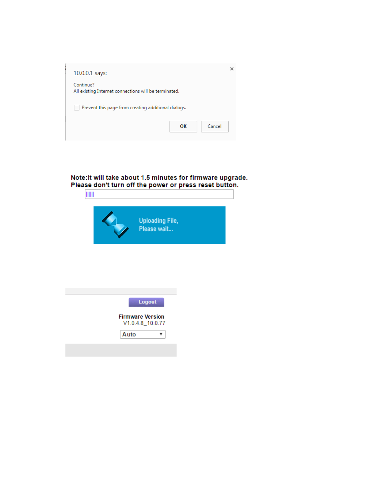
□ On the pop up widow selected OK
□ Wait as the firmware is updated
□ Once the firmware is updated the router will reset you will have to log back in using the admin
user and keepass password for the router. Once logged in verify that the firmware version has
been up dated to V1.0.4.8_10.0.77 in the upper right hand corner.

SG360-ISM-004 | REV F
73
9. Wireless Adaptor Firmware update
□ Connect the Ethernet cable to the Adapter’s Ethernet port. Connect the other end of the cable
to the Tool Laptop’s Ethernet port.
□ Open the Network properties by clicking: Start->Control Panel-> Network and Internet>View
network status and tasks. Then click Change Adapter Settings.
□ Select the Local Area Connection (LAN), right click it and select Properties. Select Internet
Protocol Version 4 (TCP/IPv4) and double-click it, or click on Properties.
□ Click on “Use the following IP address” to change the laptop’s IP address to 10.0.0.200 with
subnet 255.255.255.0. Click “OK”. Click “Close”. Click “No” for “Local Network” restart box.
□ Open the web browser on the Tool Laptop and navigate to the following address: http://
10.0.0.52. (Note: the web browser must be Google Chrome v10 or later, Mozilla Firefox V3.6 or
later; or Internet Explorer v9 or later. If using Google Chrome, click “Never” when the save
password box appears.). The login page will open. Enter the login info and password found in
Keepass
□ Update the firmware to the latest version before continuing. Navigate to the thumb drive select
AWK1131A_1.12_Build_171031018.rom. Select the button “Firmware Upgrade and Restart”.

SG360-ISM-004 | REV F
74
After the device reboots, login with the Keepass username and password and insure that the
firmware now reflects the latest build.
SG360-ISM-004 | REV F
75
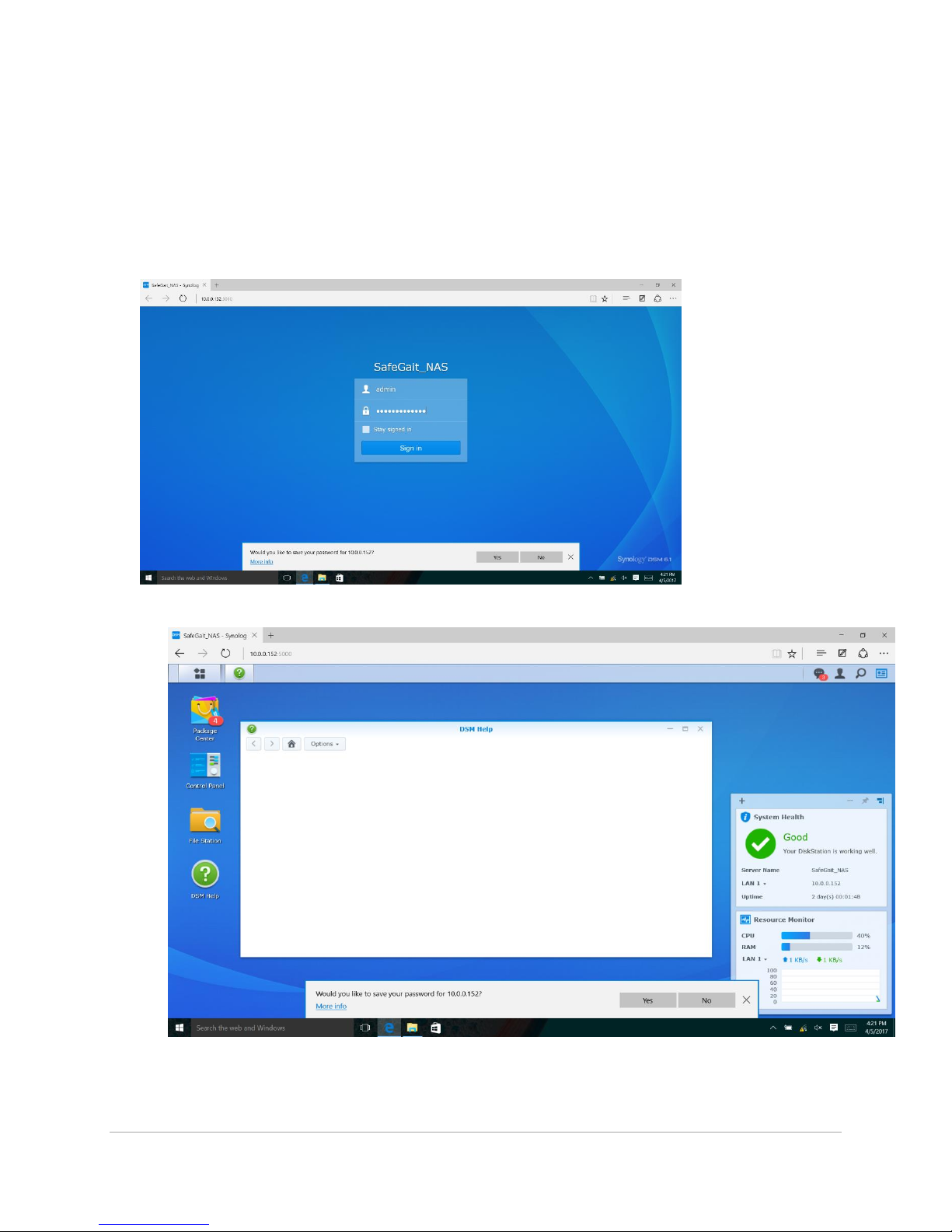
10. NAS Firmware update
□ Open a web browser and navigate to 10.0.0.152
□ Log into NAS using the administrator (admin) account using the passwords found in Keepass.
□ Click on control panel on the left side of the screen
□ Click on Update & Restore under the control panel menu

SG360-ISM-004 | REV F
76

SG360-ISM-004 | REV F
77
□ Click on Manual DSM update
□ Click the browse button on the pop up window.
□ Navigate to the SafeGait® thumb drive -> NAS firmware -> DSM_RS214_15047

SG360-ISM-004 | REV F
78
Horizontal Linear Bearing Replacement:
1. Follow the procedure for removing the Actuator from the rail.
2. Remove M6x80 screws from horizontal drive
3. Slide pressure drive wheel carriage off of linear bearing
4. Remove springs and washers from assembly
5. Remove (2) DRIVE SPRING BLOCK one on each side of the Friction Wheel. Pull (8) LOCKWASHER
M5 HIGH COLLAR and (8) SHCS M5X30.

SG360-ISM-004 | REV F
79
6. Remove (8) SHCS M3X20 and (8) LOCK WASHER, HIGH COLLAR, M3, ZINC PLATE. Remove
bearings off the rail. Remove (6) SHCS M3X14 from linear rails.
7. Remove the (2) 6MM X 12MM shoulder bolts from the pressure drive wheel block. Remove (2)
TROLLEY GUIDE WHEEL UPPER ASSEMBLY one on each Drive Guide Block. Remove (4) SPRING
WHEEL SPACER one on each side of each Guide Wheel. Take (2) SHOULDER BOLT 6MM X
12MM and apply (1) drop of Vibra-Tite VC-3 threadlocker to each. Drag the drop of
threadlocker along the length of the thread. Set aside and allow to dry a minimum of 10
minutes before using in the assembly
8. Remove (8) SHCS M3X20 and (8) LOCK WASHER, HIGH COLLAR, M3, ZINC PLATE that connect
the pressure drive block to the bearing.

SG360-ISM-004 | REV F
80
9. Attach (2) DRYLIN T RAIL, 110 MM LONG, TS-04-15-110 one on each side of the large cutout in
the center of the Plate. Secure with (6) SHCS M3X14 and (6) LOCK WASHER, HIGH COLLAR, M3,
ZINC PLATE. Tighten screws securely using the 2.5mm Hex Bit. Use the Vernier Calipers to set
the position of the second rail to the first. Measure at both ends to insure it is parallel. The
measurement at each end must be within .005”. Tighten screws securely using the 2.5mm Hex
Bit. Install (4) DRYLIN T SHUTTLE, TW-04-15 (9-0-02076), two on each Drive Linear Rail.
Carriages must slide freely on the rails.
10. Take (1) HORIZONTAL DRIVE CORE ASSEMBLY and place it on the two Drive Linear Carriages
closest to the operator. Secure with (8) SHCS M3X20 and (8) LOCK WASHER, HIGH COLLAR, M3,
ZINC PLATE. Do not fully tighten. Slide the Drive Core Assembly up against the edge of the Plate
cutout to align the assembly to the previously aligned rails. While in this position, tighten
screws securely using the 2.5mm Hex Bit. Slide the Drive Core Assembly back and forth on the
Rail to confirm free movement. If binding is noted, repeat alignment process.
11. Attach (2) DRIVE SPRING BLOCK one on each side of the Friction Wheel. Secure with (8)
LOCKWASHER M5 HIGH COLLAR and (8) SHCS M5X30. Tighten screws securely to fully
compress the lock washers using the 4mm Hex Bit. The Block must be flush to the Drive Core
surface; no gap allowed.

SG360-ISM-004 | REV F
81
12. On the remaining carriage blocks, attach (2) DRIVE GUIDE BLOCK one on each side of
the Friction Wheel. Secure with (8) SHCS M3X20 and (8) LOCK WASHER, HIGH COLLAR,
M3, ZINC PLATE. Tighten screws securely using the 2.5mm Hex Bit. Slide guide blocks
on to bearing rails. Install (2) SHCS M6X80 FULL THREAD, one each through the Drive
Core Assembly ears. Do not thread into Guide Blocks at this time.
13. Insert (3) WASHER LARGE DIAMETER #8 two into the Drive Spring Block and one into the Drive
Guide Block. Install (1) DIE SPRING 2" LG into the drive spring block. Slide the Guide Block
towards the Spring Block to trap the Die Spring. Repeat the above steps for other side using (3)
WASHER LARGE DIAMETER #8 and (1) DIE SPRING 2" LG. Do not thread the M6x80 screws into
Guide Blocks at this time.
14. Install (2) TROLLEY GUIDE WHEEL UPPER ASSEMBLY one into each Drive Guide Block. When
assembling, install (4) SPRING WHEEL SPACER one on each side of each Guide Wheel. Secure
with the (2) 6MM X 12MM shoulder bolts previously set aside, one through each Block and
Guide Wheel. Tighten securely using the 3mm Hex Bit.
15. Follow procedure to install the Actuator on the rail.

SG360-ISM-004 | REV F
82
4 Pole Hanger Clamp:
1. Using condutix conductor bar removal tool loosen conductor bars from clip
2. Loosen two M4x6 and slide clip out of rail
3. Replace clip and tighten M4x6 with M3 Allen key
4. Replace conductor bars.
WARNING: Arc flash is possible during power-up after service if the conductor
shoes are not installed in the correct conductor bars.
DANGER: Power system down and lock out power panel prior to working on
conductor bars or clips. Failure to comply may result in injury or death!

SG360-ISM-004 | REV F
83
Conductor Shoe Replacement:
(Note: single conductor shoe starting with Actuator serial number 9101200C-0001)
1. Remove power cables from the back of the conductor shoes.
2. Remove mounting screws to remove conductor shoe assembly from bracket.
3. Install new shoe assembly on bracket and secure with previously removed screws.
4. Install power cables on the back of the shoe. NOTE: install L1 on the top shoe, L2 on the
second shoe, L3 on the third shoe and GND to the bottom (green) shoe.
WARNING: Arc flash is possible during power-up after service if the conductor
shoes are not installed in the correct conductor bars.
 Loading...