

Page 1
Adjustable Armrest Kit
5144
New Hope, MN 55428
Visit us on the web:
www.safcoproducts.com
CODE
A
Armrest Bracket 1 5143-54
B
Left Armrest 1 5144-02
C
Bolt 4 5143-22
D
Washer 4 5143-21
E
Right Armrest 1 5144-03
F
Screw, Phillips Pan Head 4 5143-27
(for seats with PU (flat) bottom)
Screw, Plastite 4 5143-28
G
(for seats with PLASTIC (ribbed) bottom)
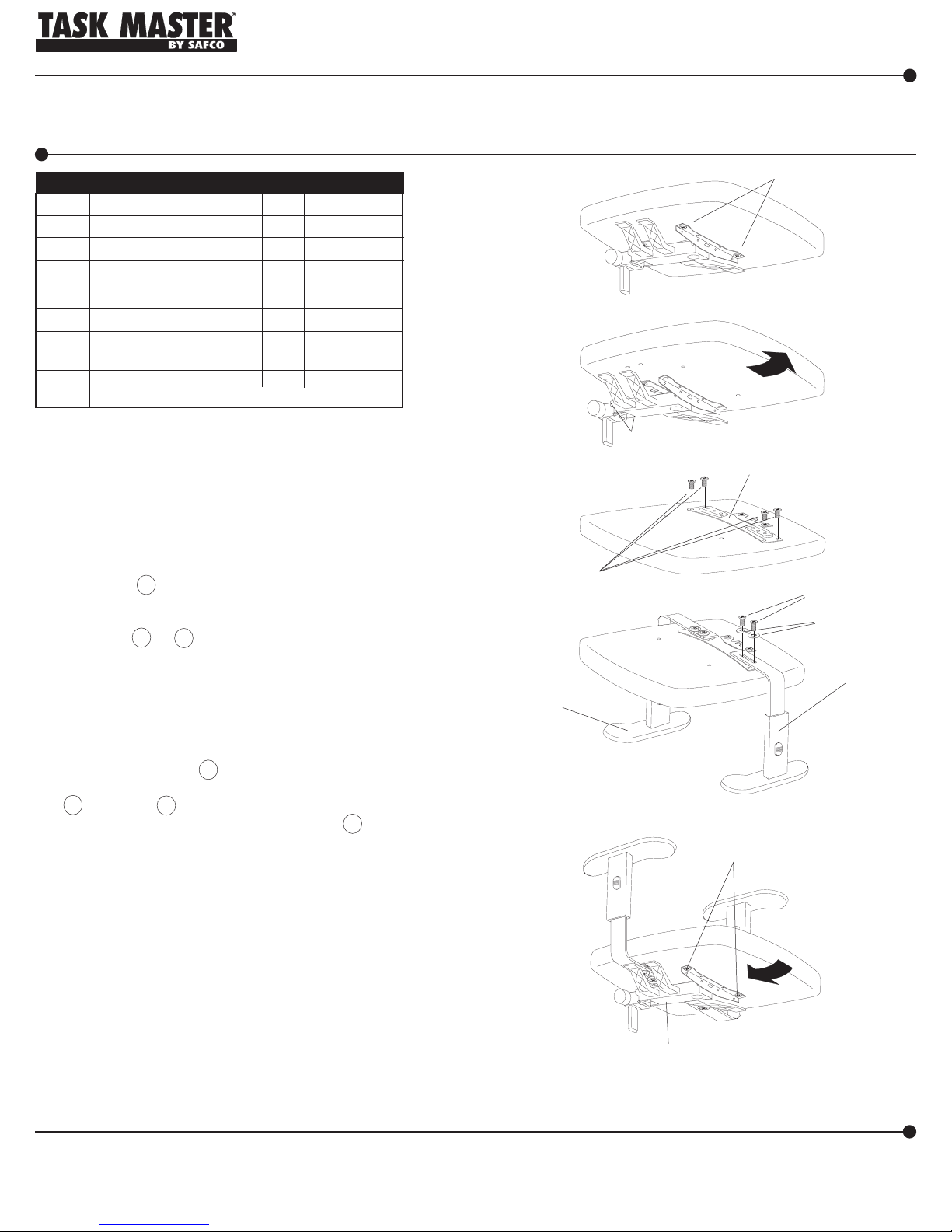
Remove the two screws at the front of the control mecha-
1
nism under the seat. IMPORTANT: save the screws for
later use.
If you can slide the seat forward and up to release it from
2
the control mechanism, do so; if not, remove the remaining
two screws at the back of the control mechanism.
IMPORTANT: save the screws for later use.
Mount the A Armrest Bracket, with the notched side facing
3
the back of the seat bottom (straddling the seat plate if
there is one). The armrest assembly comes with two types
of screws F or G ; match the screw to be used with
screws saved from Step 1 that fastened the control to the
seat. Alternately tighten each screw until securely fastened. NOTE: if a pneumatic or electric screwdriver is
used, make sure it is adjusted to not exceed 50 inchpounds of torque at 90 PSI to reduce the chance of stripping the holes.
Align the slot in the B Left Armrest with the holes in the
4
raised portion of the armrest bracket, and attach with
C Bolts and D Washers. Slide armrest to desired width,
then tighten bolts securely. Repeat with E Right Armrest.
Place the seat back onto the control mechanism; if the seat
5
has a seat plate, slide the seat backward until the prongs of
the seat plate engage the control mechanism. Align the
two front holes of the control mechanism with the holes in
the seat, and use the two screws saved in Step 1. If you
removed two screws in Step 2, replace them now. Alternately tighten all screws until securely fastened.
DESCRIPTION
PRODUCT WARRANTY CARD is available online at: www.safcoproducts.com
PARTS LISTPARTS LIST
PARTS LIST
PARTS LISTPARTS LIST
ASAS
AS
ASAS
QTY.
SEMBLSEMBL
SEMBL
SEMBLSEMBL
PART NO.
Y Y
Y
Y Y
INSTRUCTIONSINSTRUCTIONS
INSTRUCTIONS
INSTRUCTIONSINSTRUCTIONS
1
2
(OR REMOVE AND
SAVE SCREWS)
3
OR
FG
SCREWS
4
B
5
REPLACE
SCREWS
REMOVE AND
SAVE SCREWS
A
C
D
E
Please note: Fasteners should be checked
periodically and tightened as necessary.
Thank you for purchasing this Safco product. Due to
continual upgrading of our products, photographs or
illustrations may not reflect the actual (exact) appearance
of product.
5144-37MP: 1 of 3: 2/04 For questions or concerns, please call the Safco Consumer Hot Line 1-800-664-0042
available Monday-Friday 8:00 AM to 4:30 PM (Central Time) (English-speaking operators)
REPLACE SCREWS
OR
HOOK PRONGS INTO
MECHANISM
Page 2
ENSEMBLE D’ACCOUDOIR RÉGLABLE
5144
New Hope, MN 55428
S’il vous plaît visiter-nous sur l’Internet :
www.safcoproducts.com
PARTS LISTPARTS LIST
PARTS LIST
PARTS LISTPARTS LIST
CODE
A
Support d’accoudoir 1 5143-54
B
Bras gauche d’accoudoir 1 5144-02
C
Boulon 4 5143-22
D
Rondelle 4 5143-21
E
Bras droit d’accoudoir 1 5144-03
F
Vis, Phillips cuvette tête 4 5143-27
(pour sièges avec PU (plat) fond)
Vis, Plastite 4 5143-28
G
(pour sièges avec le PLASTIQUE (
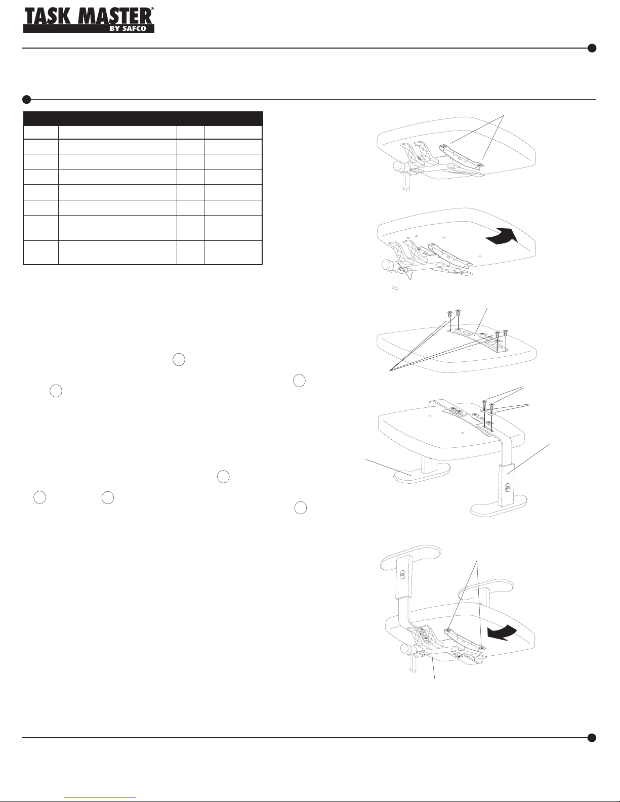
Enlevez les deux vis au devant du mécanisme du contrôle sous le
1
siège. IMPORTANT : gardez les vis pour usage plus tardif.
Si vous pouvez glisser le siège au devant et alors ascendant le
2
dégager du mécanisme du contrôle, faites donc; si pas, enlevez le
restant deux vis au dos du mécanisme du contrôle. IMPORTANT :
gardez les vis pour usage plus tardif.
DESCRIPTION
à côtes
INSTRUCTIONS DE MONTINSTRUCTIONS DE MONT
INSTRUCTIONS DE MONT
INSTRUCTIONS DE MONTINSTRUCTIONS DE MONT
Le formulaire d’inscription de garantie du produit est disponible à : www.safcoproducts.com
QTY.
) fond)
PART NO.
1
2
3
(OU ENLEVEZ ET
GARDEZ LES VIS)
AGEAGE
AGE
AGEAGE
ENLEVEZ ET
GARDEZ LES VIS
A
Attachez le Support d’Accoudoir A , avec le côté encoché qui fait
3
face au dos du fond du siège (enfourchez la plaque du siège si on
existe). L’assemblée d’accoudoir vient avec deux types de vis F
ou G . Égalez le vis être utilisé avec les vis a retenu d’instruction 1
que précédemment a attaché le contrôle au siège. Serrez chaque
vis en alternant d’un à l’autre jusqu’à ce qu’ils soient bien attachés.
NOTEZ : si un tournevis pneumatique ou électrique est utilisé,
assurez-vous il est ajusté pour ne pas dépasser livres de 50 pouces
de moment de rotation à 90 PSI (livres par pouce du carré) réduire
la possibilité de ruiner les fil du trou.
Alignez la rainure dans l’Accoudoir Gauche B avec les trous dans
4
la portion levé du support d’accoudoir, et attache avec les Boulons
C et Rondelles D . Glissez accoudoir à largeur désirée, alors
serrez des verrous solidement. Répétez avec Accoudoir Droit E .
Remplacez le siège sur le mécanisme du contrôle. Si le siège a une
5
plaque du siège, glissez le siège jusqu’à les dents de la plaque du
siège en arrière engagez le mécanisme du contrôle. Alignez les
deux trous du devant du mécanisme du contrôle avec les trous
dans le siège, et utilisez les deux vis sauvés dans instruction 1. Si
vous aviez enlevé deux vis dans instruction 2, remplacez-les
maintenant. Alternativement serrez tous les vis jusqu’à a attaché
solidement. Alignez les deux trous du devant du mécanisme du
contrôle avec les trous dans le siège, et utilisez deux vis fournis
l’Assemblée d’Accoudoir. Serrez tous les vis en alternant d’un à
l’autre jusqu’à ce qu’ils soient bien attachés.
FG
4
B
5
OU
VIS
C
D
E
REMPLACEZ LES VIS
Noter S.V.P. : Il faut vérifier les vis et les boulons de temps en
temps et les serrer s’il y a lieu.
Merci d’avoir acheté ce produit Safco. L’amélioration de nos produits se
poursuit sans cesse, et il se peut donc que les photographies ou les
illustrations ne correspondent pas (dans tous les détails) à l’apparence
du produit.
5144-37MP: 2 of 3: 2/04
Pour toute question ou tout problème, veuillez communiquer avec l’Assistance téléphonique à la clientèle
Safco au 1-800-664-0042 du lundi au vendredi, de 8H00 à 16H30 (Heure centrale) (Opérateurs de langue anglaise)
REMPLACEZ LES VIS OU
ACCROCHEZ LES DENTS
DANS LE MÉCANISME
Page 3

JUEGO DE DESCANSABRAZOS AJUSTABLE
5144
New Hope, MN 55428
Por favor visítenos en la Internet:
www.safcoproducts.com
PARTS LISTPARTS LIST
PARTS LIST
PARTS LISTPARTS LIST
CODE
A
Soporte para el descansabrazo 1 5143-54
B
Descansabrazos izquierdo 1 5144-02
C
Perno 4 5143-22
D
Arandelas 4 5143-21
E
Descansabrazos derecho 1 5144-03
F
Tornillo, Phillips Cazuela Cabeza
(para los asientos con PU (plano) el fondo)
Tornillo, Plastite 4 5143-28
G
(para los asientos con PLÁSTICO (rebordes) el fondo)
Remueva los dos tornillos al frente del mecanismo del mando bajo el
1
asiento. IMPORTANTE: retenga los tornillos para después uso.
Si usted puede resbalar el asiento al frente y entonces hacia arriba
2
para desasirlo del mecanismo del mando, haga para que; en caso
negativo, remueva los dos tornillos restantes al trasero del mecanismo
del mando. IMPORTANTE: retenga los tornillos para después uso.
DESCRIPTION
INSTRUCCIONES DE ENSAMBLAJEINSTRUCCIONES DE ENSAMBLAJE
INSTRUCCIONES DE ENSAMBLAJE
INSTRUCCIONES DE ENSAMBLAJEINSTRUCCIONES DE ENSAMBLAJE
El formulario de Registro de Garantía de Productos está disponible a: www.safcoproducts.com
PART NO.
QTY.
4 5143-27
1
2
3
REMUEVA Y AHORRE
LOS TORNILLOS
(O REMUEVA Y AHORRE
LOS TORNILLOS)
A
Ate el descansabrazo anaquel A , con el lado escotado que enfrenta el
3
trasero del fondo del asiento (la montura el plato del asiento si uno
existe). La asamblea del brazo viene con dos tipos de tornillos F o
G . Empareje el tornillo a ser usado con los tornillos retuvo de
instrucción 1 que previamente ató el mando al asiento. Aprete cada
tornillo alternando de uno al otro hasta que ellos se aten bien. LA
NOTA: si un destornillador neumático o eléctrico se usa, asegúrese se
ajusta para no exceder 50 pulgada-libra de torsión a 90 PSI (las libras
por pulgada cuadrada) para reducir la oportunidad de despojar los
agujeros.
Alinee la ranura en el Descansabrazos Izquierdo B con los agujeros
4
en la porción levantada del anaquel del descansabrazos, y ata con los
Pernos C y Arandelas D . El descansabrazos de la Diapositiva a la
anchura deseada, entonces aprete los pernos firmemente. Repita con
el descansabrazos Derecho E .
Reemplace el asiento hacia el mecanismo del mando. Si el asiento
5
tiene un plato del asiento, resbale el asiento hacia atrás hasta los
dientes del plato del asiento comprometa el mecanismo del mando.
Encuadre los dos agujeros del frente del mecanismo del mando con
los agujeros en el asiento, y use los dos tornillos retenidos en
instrucción 1. Si usted quitara dos tornillos en instrucción 2,
reemplácelos ahora. Alternadamente aprete todos los tornillos
firmemente hasta ató. Encuadre los dos agujeros del frente del
mecanismo del mando con los agujeros en el asiento, y use dos
tornillos proporcionados con la Asamblea del Descansabrazos. Aprete
todos los tornillos alternando de uno al otro hasta que ellos se aten
bien.
Aviso: Revise los tornillos periódicamente y apriételos
cuando sea necesario.
Muchas gracias por comprar este producto Safco. Debido a que
continuamente actualizamos y mejoramos nuestros productos,
la apariencia real (exacta) del producto podría ser distinta a las
fotografías o ilustraciones.
FG
O
TORNILLOS
4
B
5
REEMPLACE LOS TORNILLOS
O ENGANCHE LOS DIENTES
EN EL MECANISMO
C
D
E
REEMPLACE LOS
TORNILLOS
5144-37MP: 3 of 3: 2/04
Para dudas o preguntas, favor de llamar a Línea directa para el cliente de Safco 1-800-664-0042
Disponible lunes-viernes de 8:00 AM a 4:30 PM (Hora Central) (Operadores que hablan inglés)
 Loading...