

Page 1
4900 Industry Drive
Central Point, OR 97502
Visit us on the web:
www.ergoindemand.com
TASK MASTER® INDUSTRIAL CHAIR
(17” - 35” Range)
ASAS
AS
ASAS
TOOLS REQUIRED: 1/2" CRESCENT OR SOCKET WRENCH; SCREWDRIVER; RUBBER MALLET
SEMBLSEMBL
SEMBL
SEMBLSEMBL
Y Y
Y
Y Y
INSTRUCTIONSINSTRUCTIONS
INSTRUCTIONS
INSTRUCTIONSINSTRUCTIONS
5120
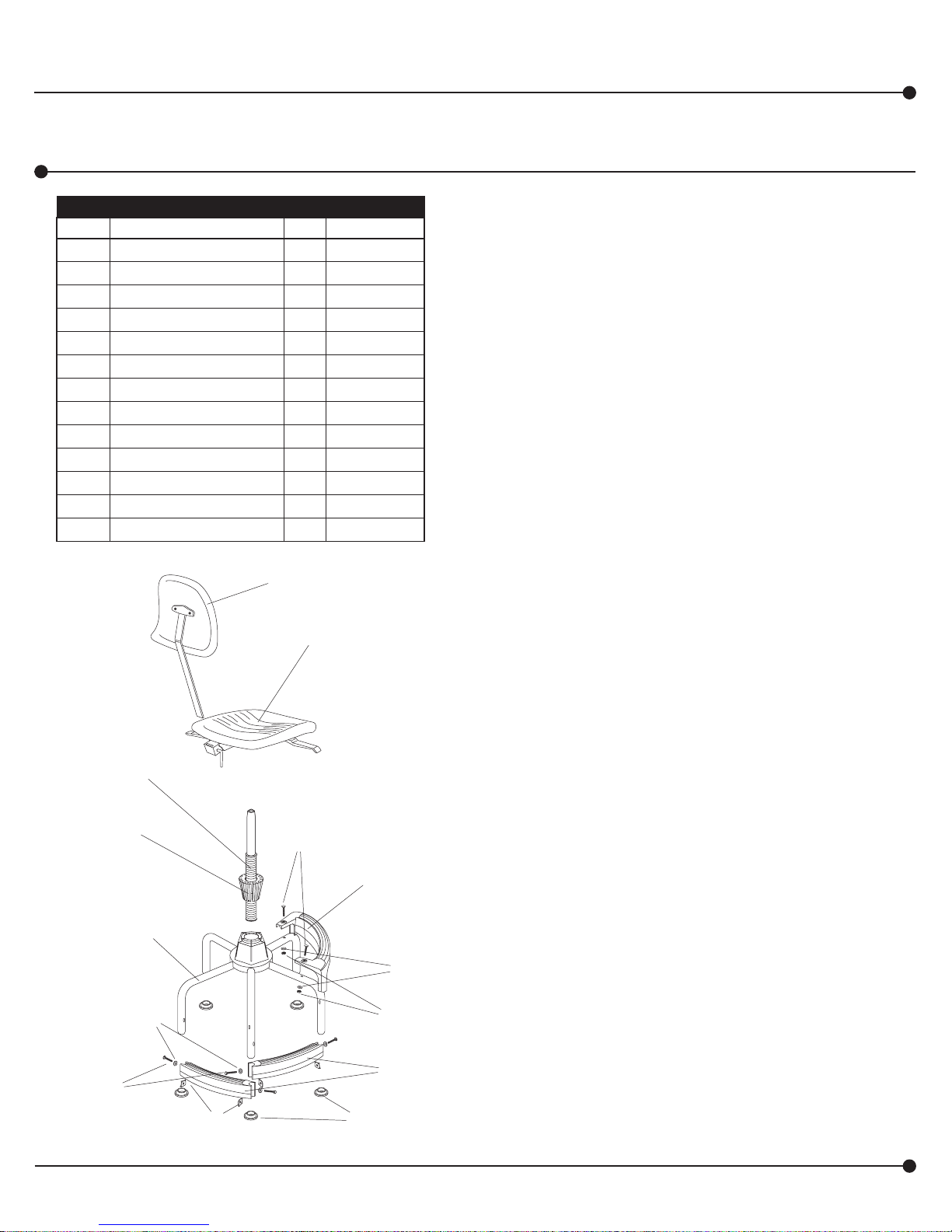
PARTS LISTPARTS LIST
PARTS LIST
PARTS LISTPARTS LIST
CODE
Base 1 5101-04
A
Q
Lower Footrest 2 5101-06
B
Q
Footrest Nut 4 5101-24
C
Q
Flat Washer 6 5147-31
D
Q
Hex Bolt 4 5101-23
E
Q
Glide 5 5101-25
F
Q
Upper Footrest 1 5118-06
G
Q
Carriage Bolt (Black) 2 5118-23
H
Q
Locking Nut 2 5118-24
I
Q
Tapered Bushing (on K) 1 5101-05
J
Q
Wavetube Assembly 1 5101-11
K
Q
Seat Assembly 1 5113-01BL
L
Q
Back Assembly 1 5113-02BL
M
Q
DESCRIPTION
M
QQ
Q
QQ
QTY.
L
QQ
Q
QQ
PART NO.
Check all parts against Parts List before beginning assembly.
Allow all parts to warm to room temperature prior to assembly.
Locate the HIGHER set of mounting holes on the side of the legs
1
of the (A) Base. From the bottom, slide a (B) Lower Footrest (with
the curved front facing out) up between those legs until the holes
in the footrest line up with those in the legs. Place a (C) Footrest
Nut inside the footrest, with the cupped side matching the curve
of the footrest end. Insert a (D) Flat Washer on to (E) Hex Bolt
through the hole in the base leg and the footrest, and thread it into
the footrest nut. Attach the other end of the footrest the same
way. Now tighten bolts alernately with a wrench, until both sides
are evenly tight. Do not overtighten.
Mount the second (B) Lower Footrest into the LOWER set of
2
mounting holes on the legs, using the same procedure as before.
Install a (F) Glide onto each of the legs of the base. The glides
3
should fit snugly, so place a glide under a leg and tap the leg into
it with a rubber mallet. Be sure the leg is inserted completely into
the glide for proper stability. (HINT: Glides are easier to install if
they are slightly expanded. Use a blow dryer or warm water,
drying thoroughly, to expand glides.)
Position the (G) Upper Footrest over the holes on the tops of two
4
of the base legs. Insert a (H) Carriage Bolt (Black) through each of
the footrest holes and through the legs. Add (D) Flat Washer and
fasten with (I) Locking Nuts on the underside of the legs; tighten
alternately with a wrench, until both sides are evenly tight. Do not
overtighten.
K
QQ
Q
QQ
J
QQ
Q
QQ
A
QQ
Q
QQ
D
QQ
Q
QQ
E
QQ
Q
QQ
C
QQ
Q
QQ
Registered U.S. Patents 5,836,555; D381,823
5120-37MP: 1 of 6;
Rev. 4: 11/06 (8004.04)
H
QQ
Q
QQ
The (J) Tapered Bushing should come preassembled on (K)
5
Wavetube (contact Ergo if it is not). Spread the tapered bushing
slightly (it has a split side) and slide to about halfway down
wavetube. Insert the wavetube assembly, wave surface first, into
the central hub of the base; slide it down until the tapered bushing
pops inside the hub and nests securely.
G
QQ
Q
QQ
D
QQ
Q
QQ
I
QQ
Q
QQ
B
QQ
Q
QQ
F
QQ
Q
QQ
For questions or concerns, please call
available Monday-Friday 8:00 AM to 4:30 PM (Central Time) (English-speaking operators)
Install the (L) Seat Assembly by aligning the hole on the underside
6
with the shaft of the wavetube assembly; push down firmly on seat.
Insert the stem of the (M) Back Assembly into the slot at the back
7
of the seat. Use a screwdriver to depress the push button at the
bottom of the stem and slide until the stem goes all the way
through the slot and sticks out the other side about 2". It may be
necessary to rotate the lever at the back of seat assembly
clockwise so stem will slide all the way through the slot. Rotate
the lever counterclockwise to lock the stem.
Make the final chair adjustments following the instructions on the
8
reverse side.
Ergo In Demand at 1-800-888-6024
Page 2
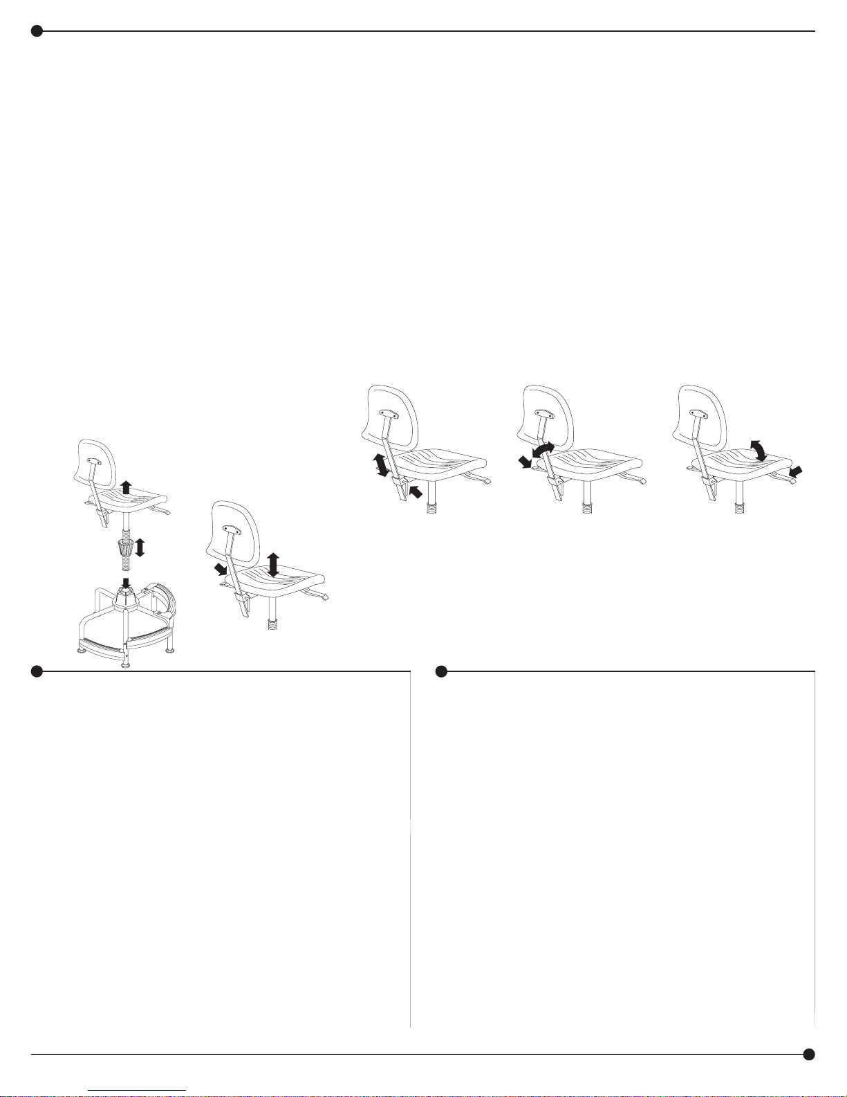
CHAIR ADJUSTMENT INSTRUCTIONS
To maximize the ergonomic benefits of this chair, it is essential to understand how the controls function and how they affect your posture.
ADJUST THE
HEIGHT RANGE:
The wavetube gives the
chair an extra 10" of height
adjustment, providing a total
seat height range of 17" to
35". Determine the
appropriate range for the
task or tasks at hand. Place
a foot on the chair base and
lift the seat with a sharp
pull. The upper chair
assembly will disconnect
from the base. Spread the
tapered bushing and move
it along the wavetube to the
desired position (toward the
seat for lower height range,
toward the open end for
higher ranges). Do not let
any part of the bushing
extend beyond either end
of the wavetube.
ADJUST THE
FINAL HEIGHT:
The front lever under the
seat on the left side
pneumatically adjusts the
height of the seat over a
range of about 8". The
proper height should be
determined by a
combination of variables:
the height of the work
surface, the task to be
performed and your body
size. Typically, the chair
should be high enough so
your arms form a 90o angle
at the elbow or slightly
greater. This allows for
better circulation in the
shoulders and neck area
and also reduces the
amount of fatigue in the
forearms and hands. The
feet should lie flat on the
ground or footrest. To help
insure good posture,
maintain a 90o angle at the
bend of the knees.
ADJUST THE
BACK HEIGHT:
The backrest height
adjustment lever is behind
and below the seat. By
sliding the backrest
assembly up or down, you
adjust the height of the back,
which has a lumbar support
curve to it. Sit centered on
the seat. The curve in the
backrest should fit into the
small of your back. This will
reduce the pressure on the
spinal discs, especially in
the lumbar area.
ADJUST THE
BACK ANGLE:
The back angle adjustment
lever is the rear one on the
left side, under the seat.
The 22o angle adjustment
of the backrest is especially
critical for work tasks that
require leaning forward. Lift
the lever and allow the
surface of the backrest to
support the upper body
weight by positioning it to
the natural curve of the
spine. Press down on the
lever to lock into place. The
backrest hinge should tilt
freely, to help prevent
twisting of the spine.
ADJUST THE
SEAT ANGLE:
The seat angle adjustment
lever is the one on the right
side, under the seat. The
seat tilt is important for work
tasks that require leaning
forward. The 10o tilt allows
you to lean forward without
extra pressure under the
thighs. Lift the lever and
shift your weight forward
until you find a
comfortable position, then
release the lever to lock
into place.
MAINTENANCE
The pneumatic lift in the Cylinder is
permanently lubricated at the factory and
needs no further lubrication. NEVER
LUBRICATE THE PNEUMATIC LIFT. Do not
remove clip from bottom of Cylinder. Contact
Ergo immediately if clip is missing or
damaged. Clean polyurethane seat and back
with soap and water. To repair small cuts in
polyurethane, apply a few drops of quickdrying glue into the cut and press the sides
together until the glue sets.
5120-37MP: 2 of 6; Rev. 4: 11/06 (8004.04)
GENERAL SAFETY INSTRUCTIONS
Do not stand on seat.
Chair must be on level surface to ensure proper
stability.
Only use chair when fully assembled.
Never use chair if it does not perform according
to this sheet or warranty may be void.
Immediately report any problems to Ergo and
always give the manufacturer's date code
information from the label under the seat.
CAUTION: Allow for optimum support. Never try
to position Tapered Bushing below the retaining
ring at the bottom of the Wavetube. Always leave
at least 1/2" clearance between the bottom of the
Wavetube and the floor.
Ergo In Demand, Inc., Central Point, OR 97502
Page 3

4900 Industry Drive
Central Point, OR 97502
S’il vous plaît visiter-nous sur l’Internet :
www.ergoindemand.com
TASK MASTER® CHAISE INDUSTRIELLE
(GAMME DE HAUTEURS DE 43 À 89 CM [17 À 35 PO])
INSTRUCTIONS DE MONTINSTRUCTIONS DE MONT
INSTRUCTIONS DE MONT
INSTRUCTIONS DE MONTINSTRUCTIONS DE MONT
OUTILS REQUIS : CLÉ À DOUILLE OU À MOLETTE 1/2 PO ; TOURNEVIS; MAILLET À TÊTE EN CAOUTCHOUC.
5120
AGEAGE
AGE
AGEAGE
CODE
ALPHABÉTIQUE
A Base 1 5101-04
Q
B Repose-pieds bas 1 5101-06
Q
C Écrou de repose-pieds 2 5101-24
Q
D Rondelle plate 4 5147-31
Q
E Boulon hexagonal 2 5101-23
Q
F Glissière 5 5101-25
Q
G Repose-pieds haut 1 5118-06
Q
H Boulon de carrosserie (noir) 2 5118-23
Q
I Contre-écrou 2 5118-24
Q
J
Q
Q
Q
Q
Brevet américain enregistré 5,836,555 ; D381,823
Manchon conique
K Ensemble de tube à filets ondulés 1 5101-11
L Ensemble de siège 1 5120-01BL
M Ensemble de dossier 1 5113-02BL
K
J
A
E
LISTE DES PIÈCES
DESCRIPTION
D
C
(sur K)
M
QTÉ.
1 5101-05
L
H
No DE PIÈCE
G
D
I
B
F
Avant de commencer le montage, vérifier toutes les pièces à l’aide
de la liste des pièces. Permettre à toutes les pièces d’atteindre la
température de la pièce avant de faire le montage.
Repérer la série HAUTE des trous de montage qui se trouvent sur les
1
côtés des pieds de la base (A) . En commençant par le bas, glisser un
repose-pieds bas (B) (avec la partie courbe vers l’avant) entre deux
pieds et le soulever jusqu’à ce que les trous du repose-pieds soient
alignés avec les trous des pieds. Mettre un écrou de repose-pieds (C)
à l’intérieur du repose-pieds, de sorte que la partie courbe de l’écrou
épouse la partie courbe de l’extrémité du repose-pieds. Glisser une
rondelle plate (D) sur le boulon hexagonal (E) , insérer le boulon dans
le trou du pied de la base et dans le trou du repose-pied, puis le visser
dans l’écrou du repose-pieds. Fixer l’autre extrémité du repose-pieds
de la même manière. Serrer les boulons peu à peu à l’aide d’une clé,
en passant de l’un à l’autre successivement jusqu’à ce qu’ils soient
bloqués également. Ne pas serrer les boulons trop fort.
Monter le deuxième repose-pieds bas (B) sur la série BASSE des trous
2
de montage qui se trouvent sur les pieds, en suivant le procédé décrit cidessus.
Installer une glissière (F) sur chacun des pieds de la base. Les
3
glissières devraient s’ajuster solidement aux pieds. Pour l’installation,
mettre une glissière au-dessous d’un pied, puis rentrer le pied dans la
glissière en le tapant avec un maillet à tête en caoutchouc. Vérifier que
le pied est inséré complètement dans la glissière, pour assurer une
bonne stabilité. (CONSEIL : Les glissières sont plus faciles à installer si
elles sont légèrement dilatées. Pour dilater les glissières, les chauffer à
l’aide d’un séchoir à air chaud, ou bien les tremper dans de l’eau
chaude, puis les essuyer avec soin.)
Positionner le repose-pieds haut (G) vis-à-vis des trous qui se trouvent
4
sur le haut de deux pieds de la base. Passer un boulon de carrosserie
(H) (noir) à travers chacun des trous du repose-pieds et à travers les
trous des pieds. Ajouter une rondelle plate (D) et attacher le reposepieds sur le dessous des pieds à l’aide des contre-écrous (I) . Serrer
les deux boulons de carrosserie peu à peu à l’aide d’une clé, en
passant de l’un à l’autre successivement jusqu’à ce qu’ils soient
bloqués également des deux côtés. Ne pas serrer les boulons trop fort.
Le manchon conique (J) devrait être déjà monté sur le tube à filets
5
ondulés (K) (communiquer avec Ergo si ce n’est pas le cas). Écarter
légèrement le manchon conique (il a une fente sur un côté), puis le
glisser à peu près au milieu de la partie ondulée du tube. Insérer
l’ensemble du tube et du manchon dans le moyeu central de la base,
avec la surface ondulée du manchon vers le bas. Glisser le manchon
vers le bas jusqu’à ce que le manchon conique rentre dans le moyeu et
s’y loge solidement.
Installer l’ensemble de siège (L) en alignant le trou du dessous avec
6
l’arbre de l’ensemble de tube à filets ondulés. Appuyer vigoureusement
sur le siège.
Insérer la tige de l’assemblée arrière (M) dans la rainure au dos du
7
siège. Utiliser un tournevis déprimer le bouton de la poussée à fond de
tige et le glisser jusqu’à la tige traverse complètement la rainure et
étend à travers l’autre côté approximativement 5 cm 2 (po). Ce peut être
nécessaire de tourner le levier au dos de l’assemblée du siège comme
les aiguilles d’une montre afin que la tige glisse complètement à
travers la rainure. Tourner le levier pour fixer la tige dans le sens
inverse des aiguilles d'une montre.
Faire les derniers règlements de la chaise en suivant les instructions au
8
verso.
5120-37MP: 3 of 6;
Rev. 4: 11/06 (8004.04)
Pour toute question ou tout problème, veuillez communiquer avec l’Assistance téléphonique à la clientèle
Ergo au 1-800-888-6024 du lundi au vendredi, de 8H00 à 16H30 (Heure du Pacifique) (Opérateurs de langue anglaise)
Page 4

INSTRUCTIONS DE RÉGLAGE DE LA CHAISE
Pour profiter au maximum des avantages ergonomiques de cette chaise, il est indispensable de savoir comment les commandes
fonctionnent et comment elles influencent votre posture.
POUR RÉGLER LA
GAMME DES
HAUTEURS :
Le tube à filets ondulés
permet un réglage
supplémentaire de la
hauteur de 25 cm (10 po).
La gamme complète des
hauteurs du siège est donc
de 43 à 89 cm (17 à 35
po). Déterminer la gamme
qui convient à la tâche ou
aux tâches à exécuter.
Mettre un pied sur la base
du tabouret, puis soulever
le siège en le tirant
brusquement vers le haut.
L’ensemble supérieur du
tabouret se détachera de
la base. Écarter le
manchon conique et le
déplacer sur le tube à filets
ondulés jusqu’à l’endroit
voulu (rapprocher le
manchon du siège pour
une gamme de hauteurs
plus basse, et de
l’extrémité ouverte pour les
gammes plus élevées). Ne
pas permettre à une partie
quelconque du manchon
de dépasser une extrémité
du tube à filets ondulés.
POUR RÉGLER LE SIÈGE
À LA HAUTEUR
DÉFINITIVE :
Le levier de devant sous
le siège sur le côté
gauche ajuste la hauteur
du siège sur une gamme
d’environ 20 cm (8 po). Il
faut déterminer la hauteur
appropriée du siège en
tenant compte de
plusieurs variables : la
hauteur de la surface de
travail, la tâche à
exécuter et la grandeur
de votre corps.
Normalement, la chaise
devrait se trouver à une
hauteur telle que vos bras
forment un angle de 90
degrés ou un peu plus au
coude. Cette posture
assure une meilleure
circulation aux épaules et
au cou, et réduit la fatigue
des avant-bras et des
mains. Les pieds
devraient être plantés
solidement sur le sol ou
sur le repose-pieds. Pour
assurer une bonne
posture, maintenir un
angle de 90 degrés aux
genoux.
POUR RÉGLER
LA HAUTEUR DU
DOSSIER :
Le levier de réglage de la
hauteur du dossier se
trouve derrière le siège et
en dessous. On peut
glisser l’ensemble de
dossier vers le haut ou
vers le bas pour régler la
hauteur du dossier, qui
est courbe pour assurer
un support lombaire. Pour
régler la hauteur du
dossier, il faut s’asseoir
avec le corps bien centré
sur le siège. La courbe du
dossier devrait épouser le
creux des reins pour
réduire la pression sur les
disques vertébraux,
surtout au niveau de la
région lombaire.
POUR RÉGLER L’ANGLE
DU DOSSIER :
Le levier de l’ajustement
de l’angle du dos est
l’arrière on sur le côté
gauche, en dessous le
siège. Le 22o ajustement
de l’angle du dossier-lit est
particulièrement critique
pour tâches du travail qui
exigent la tendance en
avant. Soulever le levier
et permettre à la surface
du dossier-lit de supporter
le poids du corps
supérieur en le plaçant à
la courbe naturelle de la
colonne vertébrale.
Presser le levier pour fixer
dans position vers le bas.
La charnière de dossier-lit
devrait incliner librement,
aider préviennent tordre
de la colonne vertébrale.
POUR RÉGLER
L’ANGLE DU SIÈGE :
Le levier du réglage pour
l’angle du siège est
localisé le côté à droite,
au-dessous du siège.
L’inclinaison du siège est
un facteur important
dans l’exécution des
tâches qui obligent une
personne à se pencher
vers l’avant. L’inclinaison
de 10 degrés permet de
se pencher vers l’avant
sans augmenter la
pression sous les
cuisses. Soulever le
levier et déplacer le
poids du corps vers
l’avant pour trouver une
posture confortable,
puis lâcher le levier pour
bloquer le siège.
ENTRETIEN
L’élévateur pneumatique du cylindre a reçu un graissage
permanent à l’usine, et n’a pas besoin d’être graissé. NE
JAMAIS GRAISSER L’ÉLÉVATEUR PNEUMATIQUE. Ne
pas enlever la bague sur le dessous du cylindre, et
communiquer avec Ergo immédiatement si la bague
manque ou est endommagée. Nettoyer le siège et le
dossier en polyuréthanne avec du savon et de l’eau. Pour
réparer les petites coupures dans le polyuréthanne, mettre
quelques gouttes d’une colle à séchage rapide dans la
coupure, puis presser les côtés ensemble jusqu’à la colle
prenne.
5120-37MP: 4 of 6; Rev. 4: 11/06 (8004.04)
CONSIGNES GÉNÉRALES DE SÉCURITÉ
Ne pas se mettre debout sur le siège.
Le tabouret doit se trouver sur une surface plane, pour
assurer une bonne stabilité.
N’utiliser le tabouret que lorsqu’il est complètement monté.
Vérifier les dispositifs d’attache de temps en temps, et les
bloquer solidement au besoin.
Ne jamais utiliser la chaise si elle ne fonctionne pas selon
les indications de la présente feuille; autrement, la garantie
risque d’être nulle et sans effet.
Rapporter tout problème à Ergo immédiatement, en citant
toujours le code de date du fabricant, qui figure sur
l’étiquette au-dessous du siège.
AVERTISSEMENT : Assurer un soutien optimal. Ne
jamais essayer de positionner le manchon conique audessous de la bague de maintien qui se trouve sur le
bas du tube à filets ondulés. Laisser toujours un
écartement d’au moins 1,2 cm (1/2 po) entre le bas du
tube à filets ondulés et le plancher.
Ergo In Demand, Inc., Central Point, OR 97502
Page 5

4900 Industry Drive
Central Point, OR 97502
Por favor visítenos en la
Internet:
www.ergoindemand.com
TASK MASTER® SILLA INDUSTRIAL
(RANGO DE ALTURA DE 48 A 68 CM [19-27"])
INSTRUCCIONES DE ENSAMBLAJEINSTRUCCIONES DE ENSAMBLAJE
INSTRUCCIONES DE ENSAMBLAJE
INSTRUCCIONES DE ENSAMBLAJEINSTRUCCIONES DE ENSAMBLAJE
HERRAMIENTAS REQUERIDAS: LLAVE DE TUERCAS DE BOCA TUBULAR O DE MEDIA LUNA DE 1/2"; DESTORNILLADOR; MAZO DE GOMA
5120
CLAVE
ALFABÉTICA
A Base 1 5101-04
Q
B
Q
Q
Q
Q
Q
Q
Q
Q
Q
Q
Q
Q
Patente 5,836,555; D381,823 registrade en EE.UU.
Apoyo para los pies inferior
C Tuerca para el apoyo para los pies 2 5101-24
D Roldana plana 4 5147-31
E Perno hexagonal 2 5101-23
F Deslizador 5 5101-25
G
Apoyo para los pies superior
H Tornillo de carruaje (negro) 2 5118-23
I Tuerca de seguridad 2 5118-24
J Casquillo cónico (colocado en K) 1 5101-05
K Tubo ondulado 1 5101-11
L Asiento 1 5120-01BL
M Respaldo 1 5113-02BL
K
J
A
E
LISTA DE PIEZAS
DESCRIPCIÓN
D
CANT.
NO. DE PIEZA
1 5101-06
1 5118-06
M
L
H
G
D
I
B
C
F
Antes de empezar a ensamblar, por favor verifique que estén
incluidas todas las piezas en la lista. Antes de ensamblar,
permita que la temperatura de las piezas alcance la temperatura
ambiente.
Localice los orificios de montaje SUPERIORES de las patas de la
1
base, (A) . Desde abajo, deslice el primer apoyo para los pies
inferior, (B) , (con la curva hacia afuera) entre esas patas hasta que
los orificios del apoyo para los pies queden alineados con los
orificios de las patas. Coloque una tuerca, (C) , en el interior del
apoyo para los pies con el lado curvo hacia la curva. Inserte una
roldana plana, (D) , en el perno hexagonal, (E) . Colóquelo a través
del orificio de la pata y del apoyo para los pies y atorníllelo en la
tuerca. Fije el otro extremo del apoyo para los pies de la misma
manera. Ahora apriete los pernos con la llave alternando entre
ellos hasta que queden igual de apretados. No apriete demasiado.
Instale el segundo apoyo para los pies inferior, (B) , en los orificios
2
de montaje INFERIORES de las patas siguiendo las instrucciones
arriba mencionadas.
Coloque un deslizador, (F) , en cada una de las patas de la base.
3
Los deslizadores deben quedar ajustados, por lo que será
necesario colocar un deslizador bajo cada una de las patas y
golpear suavemente con el mazo de goma. Para que la silla se
mantenga estable, asegúrese de que los deslizadores queden
bien insertados en las patas. (SUGERENCIA: Es más fácil colocar
los deslizadores cuando se encuentran un tanto expandidos. Para
expandirlos, utilice una secadora de pelo o agua tibia y seque
completamente).
Coloque el apoyo para los pies superior, (G) , sobre los orificios
4
localizados en la parte superior de dos de las patas. Inserte un
perno de carroza, (H) , (negro) en cada orificio atravesando el
apoyo y la pata. Coloque la roldana plana, (D) , y atornille las
tuercas de seguridad, (I) , por la parte inferior de las patas. Apriete
con la llave alternando entre los pernos hasta que queden al
mismo nivel. No apriete demasiado.
El casquillo cónico, (J) , debe venir instalado desde la fábrica en el
5
tubo ondulado, (K) , (de no ser así, comuníquese con Ergo). Abra
ligeramente el casquillo (tiene un corte vertical) y deslícelo hasta
aproximadamente la mitad del tubo ondulado. Inserte el tubo por el
extremo de las ondulaciones en el orificio central de la base y
deslícelo hacia abajo hasta que el casquillo cónico quede
insertado en forma segura dentro del orificio central.
Instale el asiento, (L) , alineando el orificio de su cara inferior con
6
el tubo ondulado y empujando firmemente el asiento hacia abajo.
Inserte el tallo de la asamblea trasera (M) en la ranura al trasero
7
del asiento. Use un destornillador para deprimir el botón al fondo
de tallo y resbalarlo hasta el tallo pasa completamente por la
ranura y se extiende a través del otro lado aproximadamente 5 cm
(2"). Puede ser necesario rodar a la izquierda la palanca al trasero
de la asamblea del asiento para que el tallo resbalara
completamente a través de la ranura. Ruede a la derecha la
palanca afianzar el tallo.
8
Para hacer los ajustes finales, siga las instrucciones que se
encuentran al reverso de esta hoja.
5120-37MP: 5 of 6;
Rev. 4: 11/06 (8004.04)
Para dudas o preguntas, favor de llamar a Línea directa para el cliente de Ergo 1-800-888-6024
Disponible lunes-viernes de 8:00 AM a 4:30 PM (Operadores que hablan inglés)
Page 6

INSTRUCCIONES PARA AJUSTAR LA SILLA
Para aumentar al máximo los beneficios ergonómicos de esta silla, es muy importante que entienda el funcionamiento de los controles y
la manera en que afectan su postura.
AJUSTE DEL RANGO
DE ALTURA:
El tubo ondulado aumenta
el rango de altura de la
silla 25 cm (10"), lo que
ofrece un rango de altura
total de 43 a 89 cm (17-35").
Determine la altura
adecuada para la tarea a
realizar. Coloque un pie
sobre la base de la silla y
levante el asiento tirando
rápida y fuertemente para
desprender la parte
superior de la silla. Abra el
casquillo cónico y
deslícelo sobre el tubo
ondulado hasta llegar a la
altura deseada (hacia el
asiento si se desea más
bajo o hacia el extremo
abierto si se desea más
alto). El casquillo no debe
sobrepasar los extremos
del tubo ondulado.
AJUSTE DE LA ALTURA
FINAL DESEADA:
La palanca que se
encuentra bajo el asiento,
del lado izquierdo (es la
que está más alejada del
respaldo), ajusta
neumáticamente la altura
en un rango de aproximadamente 20 cm (8"). La
altura adecuada se debe
determinar usando una
serie de variables tales
como la altura de la
superficie de trabajo, la
tarea a realizar y el
tamaño de su cuerpo.
Normalmente, la silla se
debe colocar a una altura
que permita que sus
brazos se doblen en un
ángulo de 90° o un poco
mayor. Esto permite una
mejor circulación de la
sangre en los hombros y
el cuello y reduce la fatiga
en los antebrazos y las
manos. Los pies deben
descansar sobre el
apoyo para los pies o el
piso. Para una buena
postura, mantenga las
rodillas dobladas en un
ángulo de 90°.
AJUSTE DE LA ALTURA
DEL RESPALDO:
La palanca para ajustar la
altura del respaldo se
encuentra bajo la parte
posterior del asiento.
Ajuste la altura del
respaldo deslizándolo
hacia arriba o hacia
abajo. El respaldo tiene
una curva que sirve de
soporte para la región
lumbar. Siéntese en el
centro de la silla de
manera que la curva
coincida con la parte
inferior de su espalda.
Esto reducirá la presión
en los discos vertebrales,
especialmente los
lumbares.
AJUSTE DEL ÁNGULO
DEL RESPALDO:
La palanca para ajustar el
ángulo del respaldo se
encuentra bajo el asiento,
del lado izquierdo. Es la
que está más cercana al
respaldo. El respaldo se
puede ajustar a un ángulo
de 22°; esto es
especialmente importante
si se trabaja inclinado
hacia adelante. Jale la
palanca hacia arriba para
liberar el respaldo de
manera que su superficie
siga la curva natural de la
columna vertebral y apoye
el peso de la parte
superior del cuerpo . Para
mantener esta posición,
empuje la palanca hacia
abajo. La bisagra del
respaldo se debe inclinar
libremente para ayudar a
evitar torceduras de la
columna.
AJUSTE DEL ÁNGULO
DEL ASIENTO:
La palanca para ajustar
el ángulo del asiento se
encuentra bajo el
asiento, del lado
derecho. La inclinación
del asiento es importante
cuando se llevan a cabo
tareas que requieren
que el cuerpo se incline
hacia adelante. Inclinar
el asiento a 10° permite
moverse hacia adelante
sin ejercer presión
adicional debajo de los
muslos. Jale la palanca
hacia arriba e inclínese
hacia adelante hasta
que quede en una
posición cómoda. Suelte
la palanca para
mantener esta posición.
MANTENIMIENTO
El elevador neumático del cilindro viene con lubricación
permanente desde la fábrica y no requiere lubricación
adicional. NUNCA LUBRIQUE EL ELEVADOR
NEUMÁTICO. No retire la pinza del extremo inferior del
cilindro. Si falta o se daña esta pinza, comuníquese con
Ergo inmediatamente. Limpie el asiento de poliuretano
con agua y jabón. Para reparar pequeñas rasgaduras
en el poliuretano, aplique unas cuantas gotas de
pegamento de secado rápido en la rasgadura y junte
las orillas hasta que seque el pegamento.
INSTRUCCIONES GENERALES DE SEGURIDAD
No se pare en el asiento.
La silla debe estar sobre una superficie nivelada para
proporcionar la estabilidad adecuada.
Utilice la silla sólo cuando esté completamente
ensamblada.
Revise periódicamente todos los tornillos y apriételos
nuevamente si es necesario.
Nunca utilice la silla si no funciona de acuerdo con las
indicaciones contenidas en esta hoja o se podría anular
la garantía.
Informe inmediatamente a Ergo acerca de cualquier
problema y siempre proporcione la información del
código de fecha del fabricante que se encuentra en la
etiqueta bajo el asiento.
PRECAUCIÓN: Obtenga el mayor soporte. Nunca trate
de colocar el casquillo cónico a un nivel más bajo
que el anillo de retención que se encuentra en el
extremo inferior del tubo ondulado. Siempre deje
por lo menos 1.2 cm (1/2") de espacio entre la parte
inferior del tubo ondulado y el piso.
5120-37MP: 6 of 6; Rev. 4: 11/06 (8004.04)
Ergo In Demand, Inc., Central Point, OR 97502
 Loading...