

Page 1
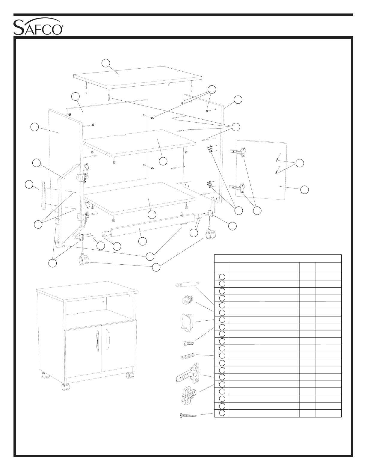
Mobile Machine Stand
ASSEMBLY INSTRUCTIONS
MODEL
NUMBER
1850
D
A
B
Q
I
S
J
T
H
L
K
N
G
M
ASSEMBLED UNIT
MODEL 1850
For questions or concerns, please call
Safco Consumer Hot Line 1-800-664-0042
available Monday-Friday 8:00 AM to 4:30 PM (Central Time)
(English-speaking operators)
TOOLS REQUIRED: Short Handled
Phillips Screwdriver; Hammer or Mallet
(Two People Recommended)
F
C
E
T
R
P
O
G
L
Sort and count your parts!
PARTS LIST
LETTER
CODE
A
Back Panel 1 1850-01
B
Left Side Panel 1 1850-03
C
Right Side Panel 1 1850-04
D
Top Panel 1 1850-05
E
Screw Post 16 HFFMFB
F
Locking Cam 16 HFFMFC
G
Caster Bracket 4 1854-10
H
Machine Screw, 5/8”L 8 1850-22
I
Fixed Shelf 1 1850-06
J
Bottom Panel 1 1850-02
K
Kick Panel 1 1850-07
L
Wood Dowel 4 H8MMDWL
M
Swivel Caster with Brake 2 8917-24
N
Swivel Caster without Brake 2 8917-25
O
Hinge 4 8919-16
P
Hinge Mount Plate 4 8919-14
Q
Left Door Panel 1 1850-08
R
Right Door Panel 1 1850-09
S
Handle 2 8962-31
T
Long Screw, 1”L 4 1850-23
DESCRIPTION
When ordering replacement parts,
please specify color.
QTY.
PART NO.
1850-37: 1 of 4; 06/02
Safco Products Company, New Hope, MN 55428
Page 2
IMPORTANT
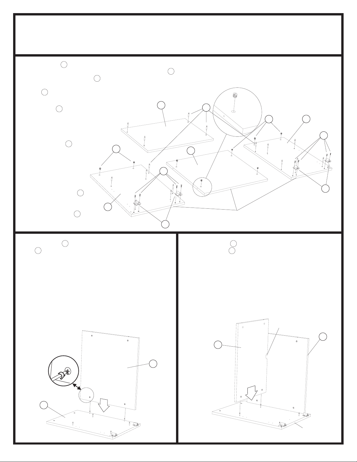
Locate the A Back Panel and lay it down on a smooth,
1
clean surface with the large holes facing up. Lay the B
Left Side Panel and the C Right Side Panel at the left and
right sides of the Back Panel with the holes facing up. Place
the D Top Panel at the finished end (put the surface with
four small holes upward).
Insert six E Screw Posts into
the small holes in the left
and right Side Panels.
Insert four more Screw
Posts into the Top
Panel. Insert F Locking
Cams into the LARGE
holes of the Back Panel
and upper end of the
Side Panels with the
arrows pointing
toward the nearest SIDE
edge. Fasten two G
Caster Brackets to the
bottom end of each side
panel using two H 5/8”
Machine Screws each.
READ and FOLLOW these instructions carefully!
CHECK ALL PACKAGING - there may be parts in it!
SORT and COUNT your parts - compare with the list below. If you find problems,
refer to the Product Warranty Registration form included with this product.
F
B
D
H
G
E
F
A
UNFINISHED
EDGES
C
H
G
Raise the A Back Panel so it is perpendicular to the
2
B Left Side Panel. Align the two Screw Posts at the
back end of the Side Panel with the corresponding
holes on the Back Panel. With the arrows on the
Locking Cams pointing toward the Screw Posts,
guide the Screw Posts into the holes and fasten by
turning each of the engaged cams CLOCKWISE as
far as they can turn.
IMPORTANT: to prevent possible damage during
assembly, a second person should help keep the
back panel supported in its upright position (or prop
upright with appropriate materials).
B
Position the I Fixed Shelf with the Cord Cutout
3
toward the A Back Panel, and the side with cams
toward the bottom end of the side panel. Align the
two Screw Posts on the Left Side Panel with the
corresponding holes on the edge of the Fixed Shelf.
With the arrows on the Locking Cams pointing
toward the Screw Posts, insert the Screw Posts and
secure by turning each of the engaged cams
CLOCKWISE as far as they can turn.
CORD
CUTOUT
A
I
A
1850-37: 2 of 4; 06/02
BOTTOM
END
Safco Products Company, New Hope, MN 55428
Page 3
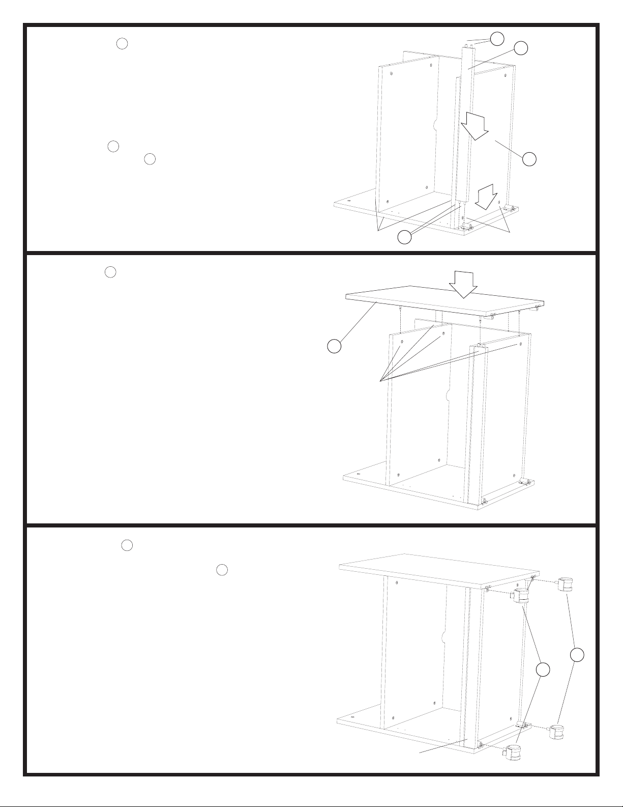
Position the J Bottom Panel so the
4
finished edge is at the front and with the
arrows on the Locking Cams pointing
toward the Screw Posts, insert the Screw
Posts into the holes on the bottom end of
the Right Side Panel and fasten by turning
the engaged cams CLOCKWISE as far as
they can turn.
Insert four L Wood Dowels into the holes
on the ends of the K Kick Panel. Insert the
Kick Panel into the Left Side Panel as
shown.
L
K
J
Raise the C Right Side Panel so it is
5
perpendicular to the work surface. Align
the Screw Posts with the corresponding
holes on the Back Panel, Bottom Panel and
Fixed Shelf (also guide the Wood Dowels
on the Kick Panel into the side panel), then
fasten by turning each of the engaged
cams CLOCKWISE as far as they can turn.
FRONT;
FINISHED EDGES
C
CAMS
L
CAMS
Push the two M Swivel Casters with Brakes
6
into the sockets of the Caster Brackets at
the front of the unit. Push the two N
Swivel Casters without Brakes into the
caster brackets near the back of the unit.
1850-37: 3 of 4; 06/02
N
M
FRONT
Safco Products Company, New Hope, MN 55428
Page 4
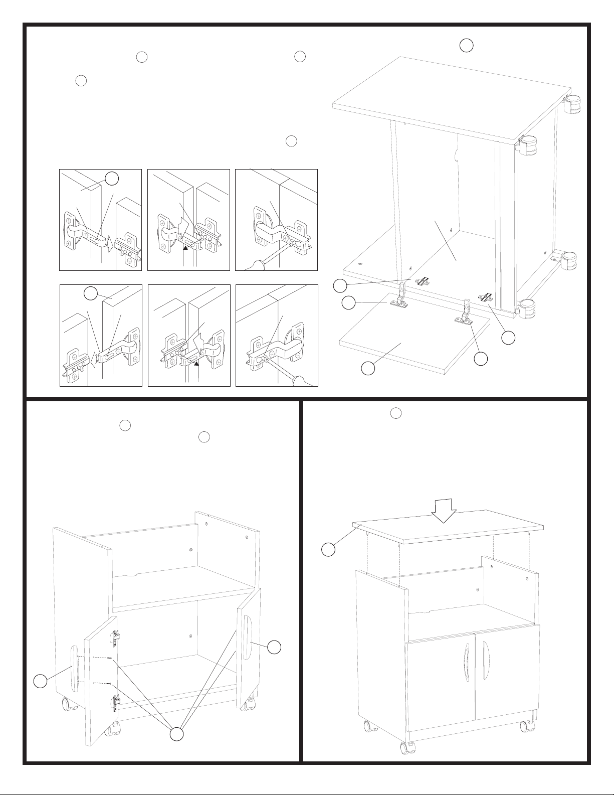
Carefully lay the unit on its left side. Using a soft hammer
7
or mallet, tap the O Hinges into the recesses on the Q
Left Door Panel. Use the pre-installed screws to fasten
the P Hinge Mount Plates into the pre-drilled holes on
the Left Side Panel. If the Hinge and Mount came in
separate pieces, bend the arms of the Hinges and insert
the slots of the arms over the Hinge Mount Plate set
screws. Adjust door position and tighten the set screws.
Turn the unit onto its right side, and repeat with the R
Right Door Panel.
R RIGHT DOOR PANEL
NOT SHOWN
Q
SLOT
ARM
SET
SCREW
R
ARM
With two people, carefully stand the unit upright.
8
Fasten one S Door Handle to the outer side of
SLOT
SET
SCREW
the Left Door Panel using two T Long Screws.
Fasten the other Door Handle to the outer side of
the Right Door Panel with two more Long Screws.
If necessary, center the Door Panels by adjusting
the set screws on the Door Hinges as needed.
TIGHTEN
SET
SCREW
TIGHTEN
SET
SCREW
LEFT
SIDE
PANEL
P
O
P
O
Q
Lower the D Top Panel down onto the side panels.
9
Guide the Screw Posts into the holes on the upper
edges of the side panels. Fasten by turning each of
the engaged cams CLOCKWISE until they stop.
Prevent the assembled unit from rolling by activating the brakes on the Swivel Casters with Brakes.
S
1850-37: 4 of 4; 06/02
D
S
T
Safco Products Company, New Hope, MN 55428
 Loading...