

Page 1
(1)
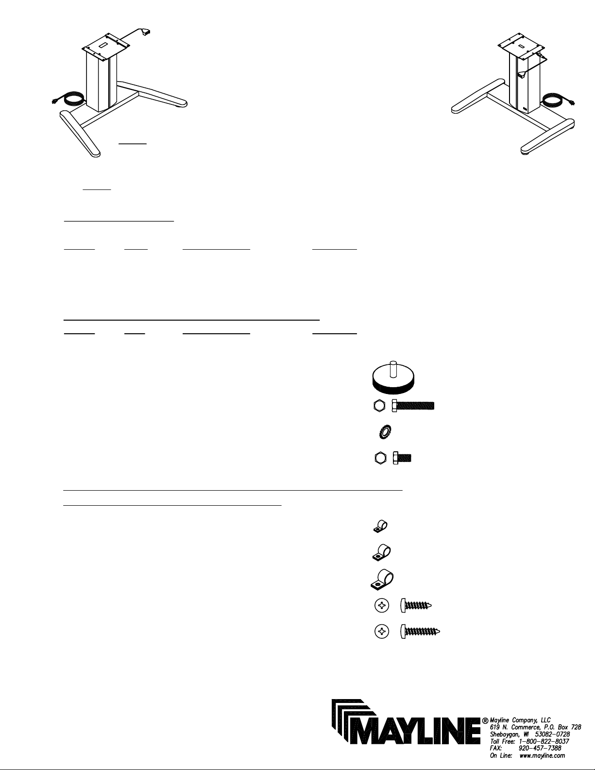
ASSEMBLY INSTRUCTIONS
for 'E' Series VariTask
NOTE: Install base so Power Plug
is easily accessible
NOTE: Bases shown with optional trim panel
NOTE: Please count and inspect all pieces before disposing of any carton or packing materials.
COMPONENTS:
REF. # QTY. DESCRIPTION PART No.
1 1 BASE ASSEMBLY CALL**
2 1 COLUMN ASSEMBLY A7641**
3 1 TOP PLATE B7052
HARDWARE BAG (PART No. A7642)
REF. # QTY DESCRIPTION PART No.
E1 1 SWITCH w/ Screws Z480*
E2 4 GLIDE Q607*
E3 4 1/4"-20 x 1 3/4" HEX SCREW D38*
E4 8 1/4" LOCK WASHER W29*
E5 4 1/4"-28 x 1/2" HEX SCREW X314*
When ordering components, specific color and/or size information may be required.
Contact a Mayline Customer Service Representative. 1-800-822-8037
*for individual item, order that part number
The following hardware is included for the proper attachment of a
Work Surface and for cable management:
** Denotes Color Code
E6 1 1/8" CABLE CLAMP F690*
E7 1 3/16" CABLE CLAMP F600*
E8 2 3/8" CABLE CLAMP F189*
E9 4 #10 x 3/4" SCREW X11*
E10 6 #10 x 1" SCREW X12*
Page 2
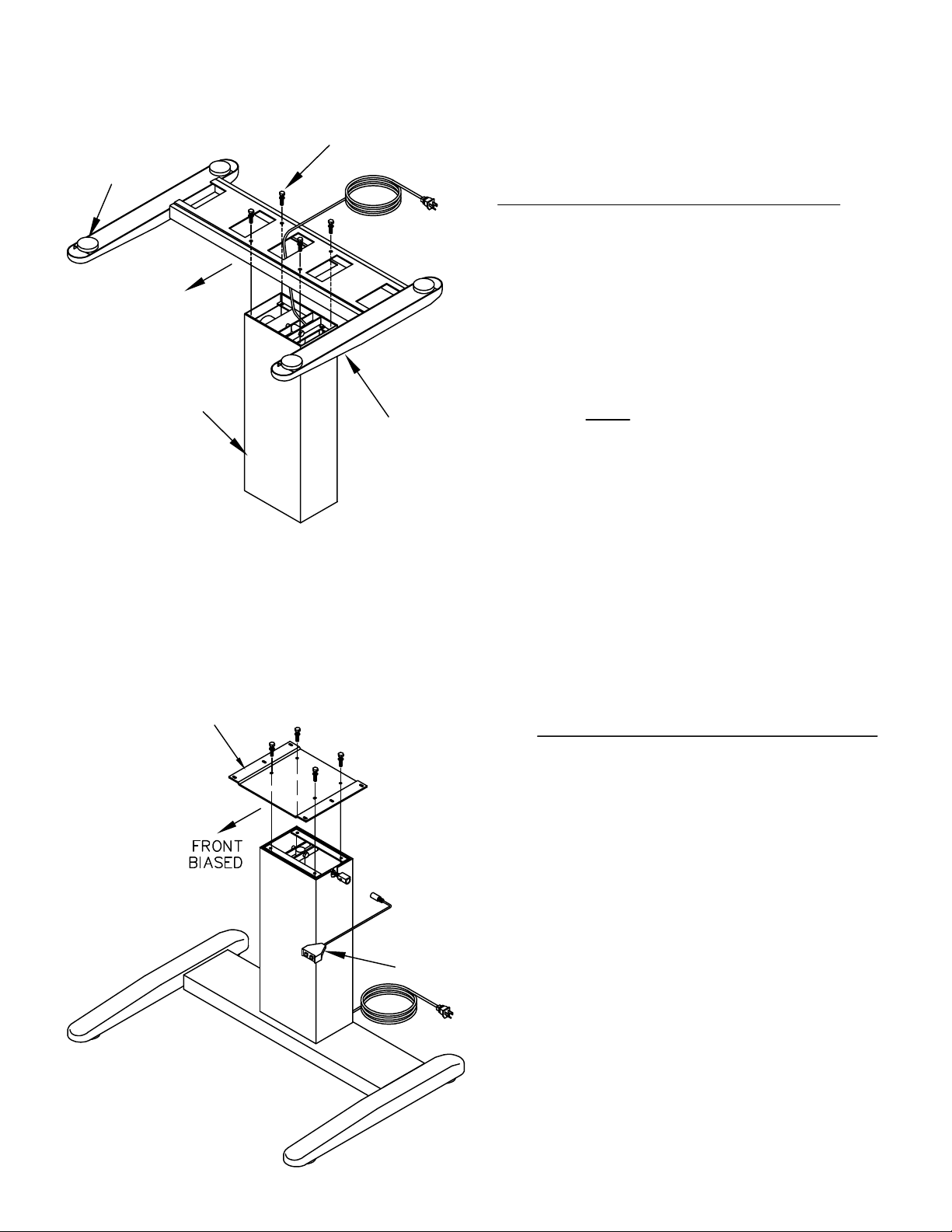
Glide (E2)
(2)
FRONT
Column (2)
Hex Head Screw (E3)
Lock Washer (E4)
MOUNTING BASE LEGS to COLUMN
1. Place Column Assembly (2) on end with Power Cord up.
2. Turn the Base Legs (1) upside-down and position the
front of the base legs toward the front of the column.
3. Carefully feed Power Cord through center opening in the
base and through center opening in bottom.
4. Position large opening in base over column and lower
into place. NOTE: Do Not pinch Power Cord.
Base Legs (1)
5. Fasten base with four 1/4-20 x 1 3/4 Hex Head Screw (E3)
and four 1/4 Lock Washer (E4).
6. Install Glides (E2) into Base Legs.
Top Plate (3)
MOUNTING TOP PLATE to COLUMN
7. Turn Column/Base upright and install Top Plate (3).
8. Place Top Plate (3) in a front biased position. (See
"Position of Top Plate" next page) Secure with four 1/4-28
x
1/2 Screws (E5) and four 1/4 Lock Washers (E4).
9. Connect Switch Assembly (E1) to Wiring Harness
extending from the Column side.
Switch Assembly (E1)
Page 3

(3)
NOTE:
For OPTIMUM knee space
under various top sizes or for
mounting accessory items to top,
you may be required to reposition
the Top Plate depending upon
the application.
Weight distribution on various
size tops, as it effects stability, is
the responsibility of the installer.
Centered
TOP PLATE POSITION #2: (Centered)
POSITION OF TOP PLATE
Lock Washer (E4)
Hex Screw (E5)
Top Plate (3)
Front
Biased
TOP PLATE POSITION #1: (Standard Position)
Column (2)
Locking Caster
Front
TOP PLATE POSITION #3: (Rotated)
Rotated and
Centered
NOTE:
For Base Assemblies equipped with optional
Casters, install Locking Casters in the front
holes of the base.
Page 4

(4)
WORK SURFACE INSTALLATION PROCEDURE
Assembled
Power Base
Screw (E10)
FRONT
ATTENTION:
MAYLINE includes screws for the installation of a Work
Surface with a minimal thickness of 1 inch (25.4mm).
NOTE:
#10 X 3/4" Screws (E9) are provided for clamp
installation only.
#10 x 1" Screws (E10) are provided for Work
Surface attachment only.
1. Place work surface face down, onto a protected
surface.
2. Invert the Power Base so the Top Plate is down.
Position the front of the Power Base toward the front
of the work surface. Secure the Base using six #10
x 1" Screws (E10).
Screws Provided
with Control
FRONT
Screw (E9)
Clamp (E6)
3. Place Hand control in desired location along front
edge. Attach using screws provided with the control.
4. Various size clamps are provided to secure
excess cable to the work surface. Position Clamps
(E6 - E7 - E8) as needed and secure with #10 X 3/4"
Screws (E9).
5. Turn the completed unit to an upright postion.
 Loading...