

Page 1
an LDI Spaces Company
Minneapolis, MN 55428
www.safcoproducts.com
TASK MASTER® INDUSTRIAL CHAIR
(19” - 27” Range)
5113
ASSEMBLY INSTRUCTIONS
TOOLS REQUIRED: Standard Screwdriver
PRODUCT WARRANTY CARD is available online at: www.safcoproducts.com
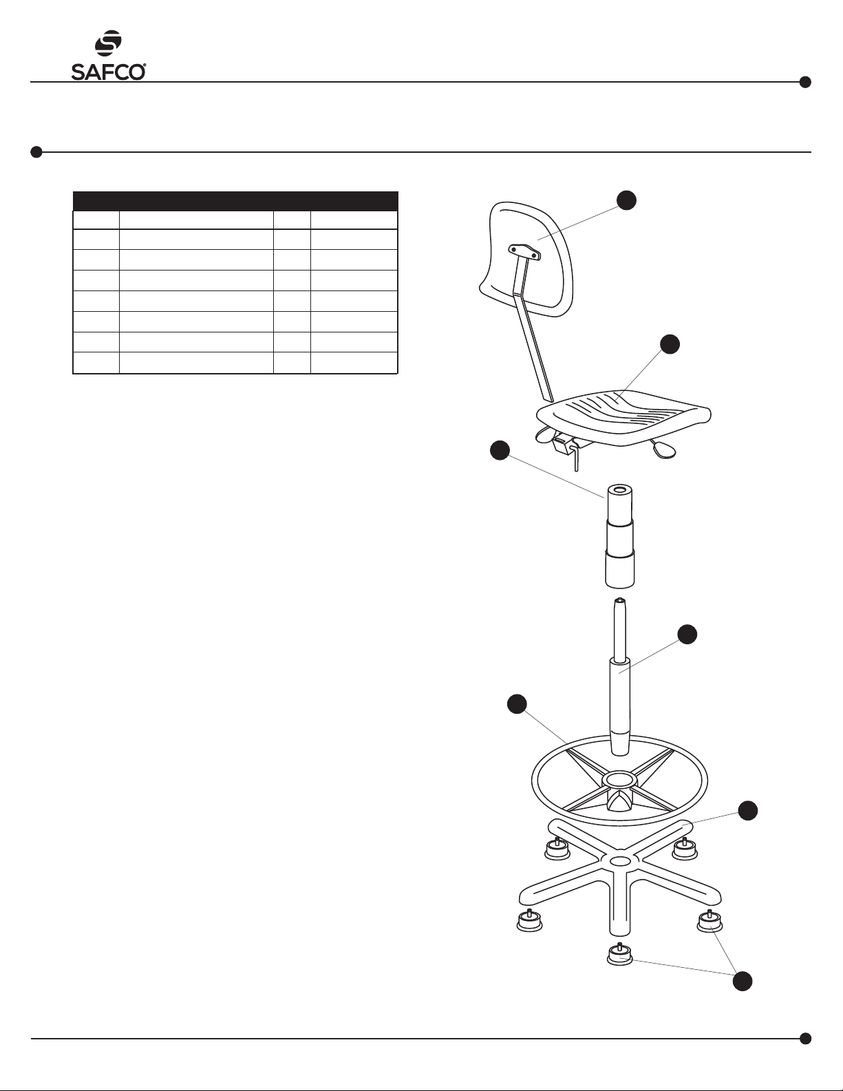
PARTS LIST
CODE DESCRIPTION
A
Glide 5 5110-75
B
Base 1 5105-04BL
C
Cylinder 1 5110-61
D
Foot Ring 1 5110-56
E
Dust Cover (3 pc set) 1 5110-64
F
Seat Assembly 1 5113-51BL
G
Back Assembly 1 5113-52BL
Check all parts against Parts List before beginning assembly. Allow all parts to warm to room
temperature prior to assembly.
Install a (A) Glide into each of the legs of the (B)
1
Base. Press fi rmly into place. Be sure the glide is
inserted completely into leg for proper stability.
Insert the (C) Cylinder into the base, tapered end
2
down. Secure the cylinder by applying a little downward pressure (CAUTION: When applying downward pressure, avoid plastic button at top of cylinder,
as pressure will release pneumatic lift)
QTY.
PART NO.
G
F
E
Slide (D) Foot Ring on to cylinder (ring side up), po-
3
sition at desired height. Turn knob to secure. Place
(E) Dust Cover over exposed cylinder.
Install the (F) Seat Assembly by aligning the hole
4
on the underside with the shaft of the cylinder; push
down fi rmly on seat.
Insert the stem of the (G) Back Assembly into the
5
slot at the back of the seat. Use a screwdriver to
depress the push button at the bottom of the stem
and slide until the stem goes all the way through the
slot and sticks out the other side about 2". It may
be necessary to rotate the lever at the back of seat
assembly clockwise so stem will slide all the way
through the slot. Rotate the lever counterclockwise to
lock the stem.
Make the fi nal chair adjustments following the instruc-
6
tions on the reverse side.
C
D
B
A
Registered U.S. Patent D381,823
100511337: 1 of 6; Rev A;
Rev Date 19-SEP-2016
For questions or concerns, please call the Safco Consumer Hot Line 1-800-664-0042
available Monday-Friday 7:30 AM to 5:00 PM (Central Time) (English-speaking operators)
Page 2
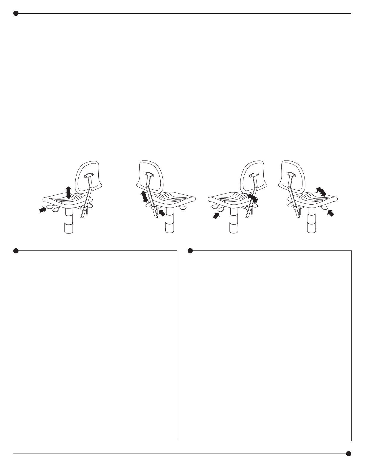
CHAIR ADJUSTMENT INSTRUCTIONS
To maximize the ergonomic benefi ts of this chair, it is essential to understand how the controls function and how they affect your posture.
ADJUST THE
HEIGHT RANGE:
The front lever under the seat on the left side
pneumatically adjusts the height of the seat over a
range of about 8". The proper height should
be determined by a combination of variables:
the height of the work surface, the task to be
performed and your body size. Typically, the chair
should be high enough so your arms form
o
angle at the elbow or slightly greater.
a 90
This allows for better circulation in the shoulders
and neck area and also reduces the amount of
fatigue in the forearms and hands. The feet should
lie fl at on the ground or footring. To help insure
good posture, maintain a 90o angle at the bend of
the knees.
ADJUST THE
BACK HEIGHT:
The backrest height
adjustment lever is behind
and below the seat. By sliding
the backrest assembly up or
down, you adjust the height
of the back, which has a
lumbar support curve to it.
Sit centered on the seat. The
curve in the backrest should
fi t into the small of your back.
This will reduce the pressure
on the spinal discs, especially
in the lumbar area.
ADJUST THE
BACK ANGLE:
The back angle adjustment
lever is the rear one on the
left side, under the seat. The
22o angle adjustment of the
backrest is especially critical
for work tasks that require
leaning forward. Pull up on
the lever and allow the surface
of the backrest to support
the upper body weight by
positioning it to
the natural curve of the spine.
Press down on the lever to
lock into place. The backrest
hinge should tilt freely, to help
prevent twisting of the spine.
ADJUST THE
SEAT ANGLE:
The seat angle adjustment
lever is the one on the right
side, under the seat. The
seat tilt is important for work
tasks that require leaning
foward. The 10o tilt allows you
to lean foward without extra
pressure under the thighs.
Lift the lever and shift your
weight forward until you fi nd
a comfortable position, then
release the lever to lock into
place.
MAINTENANCE
The pneumatic lift in the Cylinder is permanently
lubricated at the factory and needs no further
lubrication. NEVER LUBRICATE THE
PNEUMATIC LIFT. Do not remove clip from
bottom of Cylinder. Contact Safco immediately if
clip is missing or damaged. Clean polyurethane
seat and back with soap and water. To repair
small cuts in polyurethane, apply a few drops of
quick drying glue into the cut and press the sides
together until the glue sets.
GENERAL SAFETY INSTRUCTIONS
Do not stand on seat.
Chair must be on level surface to ensure proper
stability.
Only use chair when fully assembled.
Never use chair if it does not perform according
to this sheet or warranty may be void.
Immediately report any problems to Safco
and always give the manufacturer's date code
information from the label under the seat.
100511337: 2 of 6; Rev A; Rev Date 19-SEP-2016
Safco Products Company, New Hope, MN 55428
Page 3

TASK MASTER® CHAISE INDUSTRIELLE
(GAMME DE HAUTEURS DE 48 À 68 CM [19 À 27 PO])
an LDI Spaces Company
Minneapolis, MN 55428
www.safcoproducts.com
LISTE DES PIÈCES
CODE
ALPHABÉTIQUE
A
Glissière 5 5110-75
B
Base 1 5105-04BL
C
Cylindre 1 5110-61
D
Tube anti-poussière (3 pièces) 1 5110-56
E
Dust Cover (3 pc set) 1 5110-64
F
Ensemble de siège 1 5113-51BL
G
Ensemble de dossier 1 5113-52BL
Avant de commencer le montage, vérifier toutes les pièces à l’aide de la
liste des pièces. Permettre à toutes les pièces d’atteindre la température
de la pièce avant de faire le montage.
DESCRIPTION
INSTRUCTIONS DE MONTAGE
OUTILS REQUIS : Tournevis standard
Le formulaire d’inscription de garantie du produit est disponible à : www.safcoproducts.com
QTÉ.
No DE PIÈCE
5113
G
F
Installer une glissière (A) dans chacun des pieds de la base (B)
1
. Pousser la glissière pour la rentrer solidement en place. Vérifi er
que la glissière est insérée complètement dans le pied, pour assurer une bonne stabilité.
Insérer le cylindre (C) dans la base, avec le bout conique vers le
2
bas. Rentrer le cylindre dans la base en exerçant une légère pression vers le bas. (AVERTISSEMENT: En exerçant une pression
vers le bas, ne pas toucher le bouton en plastique sur le haut du
cylindre, car une pression sur le bouton déclenchera l’élévateur
pneumatique.)
Glisser l’anneau repose-pieds (D) sur le cylindre, avec l’anneau
3
vers le haut, et le positionner à la hauteur voulue. Tourner le bouton pour bloquer l’anneau. Glisser le tube anti-poussière (E) sur
le cylindre.
Installer l’ensemble de siège (F) en alignant le trou sur le des-
4
sous avec l’arbre de l’ensemble de cylindre. Pousser le siège
fermement vers le bas.
Insérer la tige de l’assemblée arrière (G) dans la rainure au dos
5
du siège. Utiliser un tournevis déprimer le bouton de la poussée
à fond de tige et le glisser jusqu’à la tige traverse complètement
la rainure et étend à travers l’autre côté approximativement 5 cm
2 (po). Ce peut être nécessaire de tourner le levier au dos de
l’assemblée du siège comme les aiguilles d’une montre afi n que
la tige glisse complètement à travers la rainure. Tourner le levier
pour fi xer la tige dans le sens inverse des aiguilles d'une montre.
E
C
D
B
Faire les derniers règlements de la chaise en suivant les instruc-
6
tions au verso.
100511337: 3 of 6; Rev A;
Rev Date 19-SEP-2016
Brevet américain enregistré D381,823
A
Pour toute question ou tout problème, veuillez communiquer avec l’Assistance téléphonique à la clientèle
Safco au 1-800-664-0042 du lundi au vendredi, de 7H30 à 17H00 (Heure centrale) (Opérateurs de langue anglaise)
Page 4

INSTRUCTIONS DE RÉGLAGE DE LA CHAISE
Pour profi ter au maximum des avantages ergonomiques de cette chaise, il est indispensable de savoir comment les commandes fonctionnent
et comment elles infl uencent votre posture.
POUR RÉGLER LA GAMME
DES HAUTEURS :
Le levier de devant sous le siège sur le
côté gauche ajuste la hauteur du siège
sur une gamme d’environ 20 cm (8 po).
Il faut déterminer la hauteur appropriée
du siège en tenant compte de plusieurs
variables: la hauteur de la surface de
travail, la tâche à exécuter et la grandeur
de votre corps. Normalement, la chaise
devrait se trouver à une hauteur telle que
vos bras forment un angle de 90 degrés
ou un peu plus au coude. Cette posture
assure une meilleure circulation aux
épaules et au cou, et réduit la fatigue des
avant-bras et des mains.
Les pieds devraient être plantés solidement sur le sol. Pour assurer une bonne
posture, maintenir un angle de 90 degrés
aux genoux.
POUR RÉGLER LA HAUTEUR
DU DOSSIER :
Le levier de réglage de la hauteur du dossier se trouve derrière
le siège et en dessous. On peut
glisser l’ensemble de dossier
vers le haut ou vers le bas pour
régler la hauteur du dossier, qui
est courbe pour assurer un support lombaire. Pour régler la hauteur du dossier, il faut s’asseoir
avec le corps bien centré sur
le siège. La courbe du dossier
devrait épouser le creux des
reins pour réduire la pression sur
les disques vertébraux, surtout
au niveau de la région lombaire.
POUR RÉGLER L’ANGLE
DU DOSSIER :
Le levier de l’ajustement de l’angle
du dos est l’arrière on sur le côté
gauche, en dessous le siège.
Le 22o ajustement de l’angle du
dossier-lit est particulièrement critique pour tâches du travail
qui exigent la tendance en avant.
Soulever le levier et permettre
à la surface du dossier-lit de supporter le poids du corps supérieur en
le plaçant à la
courbe naturelle de la colonne vertébrale. Presser le levier pour fi xer
dans position vers le bas.
La charnière de dossier-lit devrait
incliner librement, aider préviennent
tordre de la colonne vertébrale.
POUR RÉGLER L’ANGLE
DU SIÈGE :
Le levier du réglage pour
l’angle du siège est localisé
le côté à droite, au-dessous
du siège. L’inclinaison du
siège est un facteur important
dans l’exécution des tâches
qui obligent une personne
à se pencher vers l’avant.
L’inclinaison de 10 degrés permet de se pencher vers l’avant
sans augmenter la pression
sous les cuisses. Soulever le
levier et déplacer le poids du
corps vers l’avant pour trouver
une posture confortable, puis
lâcher le levier pour bloquer le
siège.
ENTRETIEN
L’élévateur pneumatique du cylindre a reçu un
graissage permanent à l’usine, et n’a pas besoin d’être graissé. NE JAMAIS GRAISSER
L’ÉLÉVATEUR PNEUMATIQUE. Ne pas enlever
la bague sur le dessous du cylindre, et communiquer avec Safco immédiatement si la bague
manque ou est endommagée. Nettoyer le siège
et le dossier en polyuréthanne avec du savon
et de l’eau. Pour réparer les petites coupures
dans le polyuréthanne, mettre quelques gouttes
d’une colle à séchage rapide dans la coupure,
puis presser les côtés ensemble jusqu’à la colle
prenne.
CONSIGNES GÉNÉRALES DE SÉCURITÉ
Ne pas se mettre debout sur le siège.
La chaise doit se trouver sur une surface
plane, pour assurer une bonne stabilité.
N’utiliser la chaise que lorsqu’elle est complètement montée.
Ne jamais utiliser la chaise si elle ne fonctionne
pas selon les indications de la présente feuille;
autrement, la garantie risque d’être nulle et
sans effet.
Rapporter tout problème à Safco immédiatement, en citant toujours le code de date du
fabricant, qui fi gure sur l’étiquette au-dessous
du siège.
100511337: 5 of 6; Rev A;
Rev Date 19-SEP-2016
Para dudas o preguntas, favor de llamar a Línea directa para el cliente de Safco 1-800-664-0042
Disponible lunes-viernes de 7:30 AM a 5:00 PM (Hora Central) (Operadores que hablan inglés)
Page 5

TASK MASTER® SILLA INDUSTRIAL
(RANGO DE ALTURA DE 48 A 68 CM [19-27"])
an LDI Spaces Company
Minneapolis, MN 55428
www.safcoproducts.com
LISTA DE PIEZAS
CLAVE
ALFABÉTICA
A
Deslizador 5 5110-75
B
Base 1 5105-04BL
C
Cilindro 1 5110-61
D
Anillo de apoyo para los pies 1 5110-56
E
Forro antipolvo (juego de 3 piezas) 1 5110-64
F
Asiento 1 5113-51BL
G
Respaldo 1 5113-52BL
Antes de empezar a ensamblar, por favor verifi que que
estén incluidas todas las piezas de la lista. Antes de ensamblar, permita que la temperatura de las piezas alcance la
temperatura ambiente.
DESCRIPCIÓN
INSTRUCCIONES DE ENSAMBLAJE
HERRAMIENTAS REQUERIDAS: El Destornillador Standard
El formulario de Registro de Garantía de Productos está disponible a: www.safcoproducts.com
CANT.
NO. DE PIEZA
5113
G
F
Instale los deslizadores, (A) , en cada una de las patas de la
1
base, (B) , y presione fi rmemente. Para que la silla se mantenga
estable, asegúrese de que los deslizadores queden insertados
completamente en las patas.
Inserte en la base el extremo cónico del cilindro, (C) . Asegúre-
2
lo presionando ligeramente hacia abajo. (PRECAUCIÓN:
Cuando presione hacia abajo evite tocar el botón de plástico
que se encuentra en la parte superior del cilindro, ya que esto
accionaría el elevador neumático).
Deslice el anillo de apoyo para los pies, (D) , en el cilindro (con
3
el anillo hacia arriba), colóquelo a la altura deseada y fíjelo
girando la perilla. Cubra el cilindro con el forro antipolvo, (E) .
Para instalar el asiento, (F) , alinee el orifi cio de la parte inferior
4
del asiento con el extremo superior del cilindro y empuje fi rme-
mente el asiento hacia abajo.
Inserte el tallo de la asamblea trasera (G) en la ranura al tra-
5
sero del asiento. Use un destornillador para deprimir el botón
al fondo de tallo y resbalarlo hasta el tallo pasa completamente
por la ranura y se extiende a través del otro lado aproximadamente 5 cm (2"). Puede ser necesario rodar a la izquierda la
palanca al trasero de la asamblea del asiento para que el tallo
resbalara completamente a través de la ranura. Ruede a la
derecha la palanca afi anzar el tallo.
E
C
D
B
Para hacer los ajustes fi nales, siga las instrucciones que se
6
encuentran al reverso de esta hoja.
100511337: 5 of 6; Rev A;
Rev Date 19-SEP-2016
A
Patente D381,823 registrade en EE.UU.
Para dudas o preguntas, favor de llamar a Línea directa para el cliente de Safco 1-800-664-0042
Disponible lunes-viernes de 7:30 AM a 5:00 PM (Hora Central) (Operadores que hablan inglés)
Page 6

INSTRUCCIONES PARA AJUSTAR LA SILLA
Para aumentar al máximo los benefi cios ergonómicos de esta silla, es muy importante que entienda el funcionamiento de los controles y la
manera en que afectan su postura.
AJUSTE DEL RANGO DE ALTURA:
La palanca que se encuentra bajo el
asiento, del lado izquierdo (es la que
está más alejada del respaldo), ajusta
neumáticamente la altura en un rango de
aproxima damente 20 cm (8"). La altura
adecuada se debe determinar usando una
serie de variables tales como la altura de
la superfi cie de trabajo, la tarea a realizar y
el tamaño de su cuerpo. Normalmente,
la silla se debe colocar a una altura que
permita que sus brazos se doblen en un
ángulo de 90° o un poco mayor. Esto permite una mejor circulación de la sangre en
los hombros y el cuello y reduce la fatiga
en los antebrazos y las manos. Los pies
deben descansar apoyados sobre el piso
o sobre el anillo de apoyo. Para ayudar a
asegurar una buena postura, mantenga las
rodillas dobladas en un ángulo de 90°.
AJUSTE DE LA ALTURA
DEL RESPALDO:
La palanca para ajustar la altura
del respaldo se encuentra
bajo la parte posterior del
asiento. Ajuste la altura del respaldo deslizándolo hacia arriba
o hacia abajo. El respaldo tiene
una curva que sirve de soporte
para la región lumbar. Siéntese
en el centro de la silla de manera
que la curva coincida con la
parte inferior de su espalda. Esto
reducirá la presión en los discos
vertebrales, especialmente los
lumbares.
AJUSTE DEL ÁNGULO
DEL RESPALDO:
La palanca para ajustar el ángulo del
respaldo se encuentra bajo
el asiento, del lado izquierdo.
Es la que está más cercana al respaldo. El respaldo se puede ajustar
a un ángulo de 22°; esto
es especialmente importante si se
trabaja inclinado hacia adelante.
Jale la palanca hacia arriba para
liberar el respaldo de manera que
su superfi cie siga la curva natural de
la columna vertebral y apoye
el peso de la parte superior del cuerpo. Para mantener esta posición,
empuje la palanca hacia abajo. La
bisagra del respaldo se debe inclinar
libremente para ayudar a evitar
torceduras de la columna.
AJUSTE DEL ÁNGULO
DEL ASIENTO:
La palanca para ajustar
el ángulo del asiento se encuentra bajo el asiento,
del lado derecho. Es la que
está más alejada del respaldo.
La inclinación del asiento es
importante cuando se llevan
a cabo tareas que requieren
que el cuerpo se incline hacia
adelante. Inclinar el asiento
a 10° permite moverse hacia
adelante sin ejercer presión
adicional debajo de los muslos.
Jale la palanca hacia arriba e
inclínese hacia adelante hasta
que quede en una posición
cómoda. Suelte
la palanca para
mantener esta
posición.
MANTENIMIENTO
El elevador neumático del cilindro viene con
lubricación permanente desde la fábrica y no
requiere lubricación adicional. NUNCA LU-
BRIQUE EL ELEVADOR NEUMÁTICO. No
retire la pinza del extremo inferior del cilindro.
Si falta o se daña esta pinza, comuníquese
con Safco inmediatamente. Limpie el asiento
de poliuretano con agua y jabón. Para reparar pequeñas rasgaduras en el poliuretano,
aplique unas cuantas gotas de pegamento
de secado rápido en la rasgadura y junte las
orillas hasta que seque el pegamento.
INSTRUCCIONES GENERALES DE SEGU-
RIDAD
No se pare en el asiento.
La silla debe estar sobre una superfi cie nivelada
para proporcionar la estabilidad adecuada.
Utilice la silla sólo cuando esté completamente
ensamblada.
Nunca utilice la silla si no funciona de acuerdo
con las indicaciones contenidas en esta hoja o
se podría anular la garantía.
Informe inmediatamente a Safco acerca de cualquier problema y siempre proporcione la información del código de fecha del fabricante que
se encuentra en la etiqueta bajo el asiento.
100511337: 6 of 6; Rev A; Rev Date 19-SEP-2016
Safco Products Company, New Hope, MN 55428
 Loading...