

Page 1
Plan Master
Height Adjustable Drafting Table
an LDI Spaces Company
Minneapolis, MN 55428
www.safcoproducts.com
PRODUCT WARRANTY REGISTRATION is available online at: www.safcoproducts.com
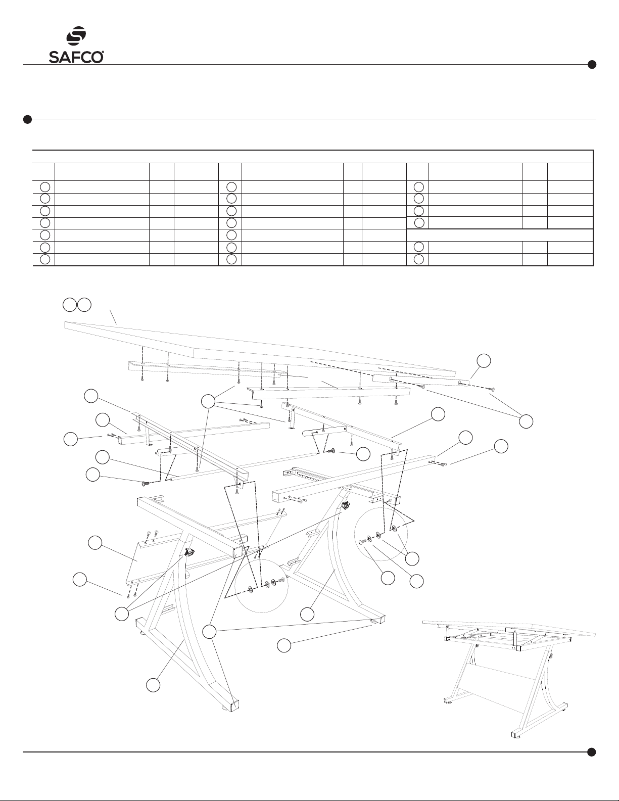
Tools required: Phillips screwdriver, hammer
(nail or pointed tool may be used to help start holes)
LETTER
CODE
A
Left Frame Assembly 1 3957-51BL
B
Right Frame Assembly 1 3957-52BL
C
Back Panel 1 3957-53BL
D
Horizontal Tube 2 3957-54BL
E
Lift Bar 1 3957-55BL
F
Left Support Channel 1 3957-60BL
G
Right Support Channel 1 3957-61BL
S
DESCRIPTION
TABLE TOP (SOLD SEPARATELY)
T
READ THESE INSTRUCTIONS BEFORE STARTING! FOLLOW THE ASSEMBLY PROCEDURES CAREFULLY.
PART NO.
QTY.
ASSEMBLY INSTRUCTIONS
PARTS LIST
LETTER
CODE
H
I
J
K
L
M
N
DESCRIPTION
Tube Plug
Large Flat Head Machine Screw
Long Pan Head Machine Screw
Pan Head Hi-Grip Screw
Nylon Spacer
Washer
Adjustment Knob, Black
8 3957-76BL
18 3957-79NC
4 3957-82NC
2 3957-71NC
2 3957-73BL
PART NO.
QTY.
2 3957-77NC
16 3957-78NC
LETTER
CODE
O
*Table Tops below sold & shipped separately
Drawing Board – 60" 1 3948*
Drawing Board – 48" 1 3951*
Leveler
P
Drawing Board Support Bar
Q
Pencil Bar
R
Short Pan Head Machine Screw
S
T
3957
DESCRIPTION QTY.
4 3957-75NC
2 3957-65BL
1 3957-83BL
2 3957-74NC
PART NO.
F
D
J
E
I
C
J
N
Adjustment Knob AT-
TENTION!
Do NOT loosen
until instruction num-
ber 9.
Q
P
K
G
K
D
I
J
L
R
M
B
H
O
A
100395737: 1 of 4; Rev A; Rev Date
05-JUL-2016
ASSEMBLED
UNIT
For questions or concerns, please call the Safco Consumer Hot Line 1-800-664-0042
available Monday-Friday 7:30 AM to 5:00 PM (Central Time) (English-speaking operators)
Page 2
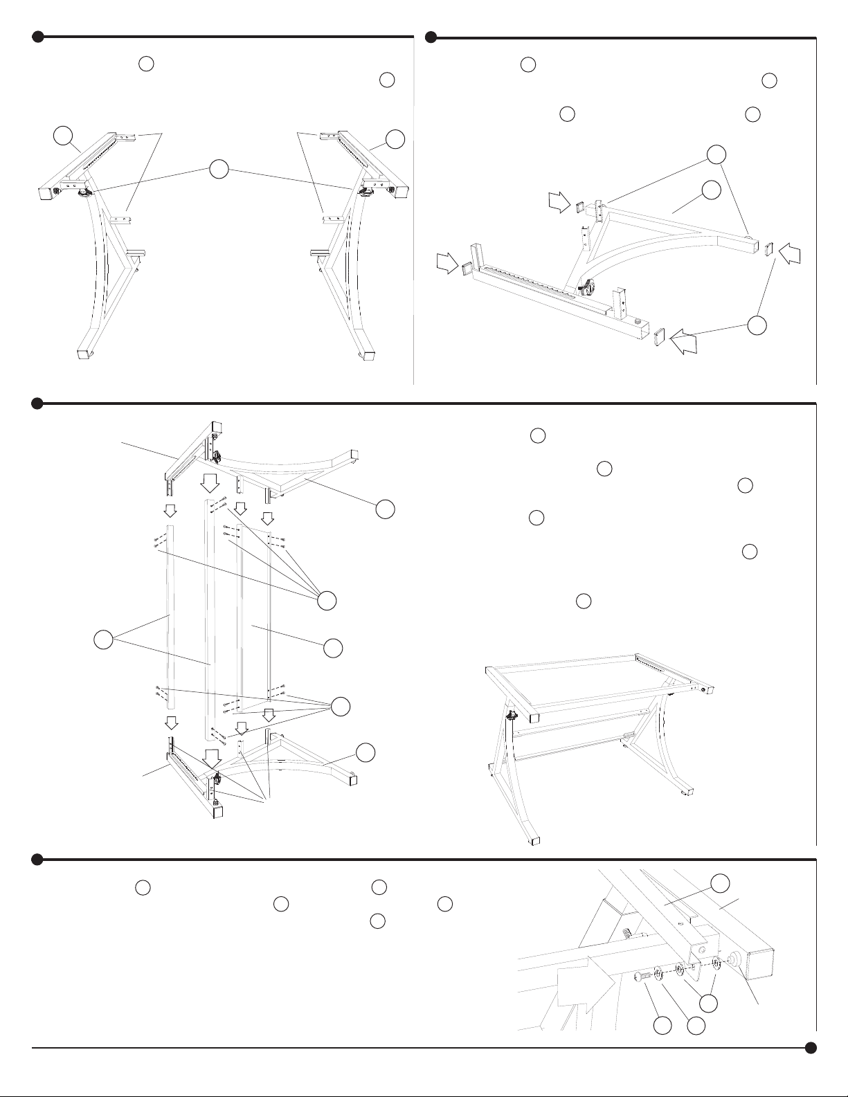
Locate the A Left Frame Assembly (the short chan-
1
nels will be on the right side of the frame), and the B
Right Frame Assembly (the short channels will be on
the left side of the frame).
A
SHORT CHANNELS
N
ATTENTION!
Do NOT
unscrew the
ADJUSTMENT
KNOBS
until the fi nal
instruction.
Place the A Left Frame Assembly on a protected
2
surface with the short channels upward. Insert the
H Tube Plugs if they are not already installed on the
tube ends. Insert the O Levelers. Repeat with the B
B
Right Frame Assembly.
O
A
H
3
OF RIGHT
ASSEMBLY
UPPER
END
FRAME
D
UPPER
END
OF LEFT
FRAME
ASSEMBLY
SHORT
CHANNELS
Insert the D Horizontal Tubes onto each of the short
channels along the upper end of the Left Frame Assembly. Attach using two J Long Pan Head Machine
Screws for each tube. Insert one end of the C Back
B
J
C
J
A
Panel onto the two lower short channels and attach
using four J Long Pan Head Machine Screws.
With the help of an assistant, carefully lift the B Right
Frame Assembly up and insert the short channels into
the open ends of the tube and back panel. Loosely
fasten using eight J Long Pan Head Machine Screws.
Carefully turn the assembled base upright.
Place one L Nylon Spacer on the pin. Insert the G Support
4
Channel onto the pin. Place one L Nylon Spacer and one M
Washer on the pin and fasten securely using one R Short Pan
Head Machine Screw. Repeat for the other support channel
and frame.
100395737: 2 of 4; Rev A; Rev Date 05-JUL-2016
G
Do Not
Overtighten.
L
M
R
Safco Products Company, New Hope, MN 55428
FRAME
HINGE
PIN
Page 3

5
Raise the G Right Support Channel and insert the channel pin into
the notched channel in the frame.
Repeat this procedure for the
F Left Support Channel.
CHANNEL
PIN
NOTCHED
CHANNEL
6
G
Attach the E Lift Bar to each channel arm through the countersunk holes using one I Large Flat Head Machine Screw at
each end.
F
E
G
I
CHANNEL
ARM
7
Prepare the Drawing Board.
Carefully open the Drawing Board
carton. Keep the Drawing Board in the
carton. Two people are required to lift
the assembled base onto the S or T
Drawing Board. Position the F and G
support channel assemblies located
on the base onto the drawing board.
Carefully center the frame from sideto-side and front-to-back. Fasten the
support channels to the drawing board
using K Pan Head Hi-Grip Screws
through each channel. Attach the Q
Pencil Bar to the front edge of the
drawing board using two K Pan Head
Hi-Grip Screws.
I
F
G
K
NOTE: if it is too diffi cult to get
the screws into the board, position
the base and use a hammer and nail
to carefully tap starter holes using the
channel holes as a guide. Then, fi nish
fastening the screws to the board.
Position the P Support Bars in between the left
8
and right support channels. The Support Bars must
be placed at least 8" in from the long edges. Attach
to the Drawing Board using four K Pan Head HiGrip Screws for each Support Bar.
When the frame is securely fastened to the
Drawing Board, turn the entire assembly upright.
100395737: 3 of 4; Rev A; Rev Date 05-JUL-2016
S or
T
Safco Products Company, New Hope, MN 55428
Q
K
P
Page 4

Lower the Drawing Board to the fl at
9
position by raising the E Lift Bar
upward with one hand while
easing the board downward
with the other hand. (see inset)
Loosen the N Adjustment Knobs
on both frames.
(ATTENTION: NEVER COMPLETELY
UNSCREW THE KNOBS!)
Standing at the FRONT of the table
(hinge pivot side), place your hands in
the center of the drawing board approximately 30 inches apart and press down
and away several times to insure proper
alignment of the telescoping tubes
within the end frames. When the movement is satisfactory, lock the drawing
board in its lowest position by tightening the knobs.
Finish tightening the eight machine
screws on the back panel, and the eight
screws that attach the D Horizontal
Tubes to the frame.
END
FRAME
HINGE
PIVOT
(FRONT)
N
INSET
LIFT BAR
OPERATING INSTRUCTIONS
Position the table in the location where
it is to be used and adjust the levelers
up or down to compensate for unlevel
fl oors.
TILT ADJUSTMENT
Automatic stops are built into the support channels for a minimum
7 degree tilt angle of the drawing
board. If a 7 degree tilt is desired,
simply lift the drawing board up
about 5". The stops will
automatically swing down into
position and rest on the frame.
If a fl at position is desired, each
stop can be swiveled off of the frame
towards the rear of the table. Be sure to
hold the drawing board up so you won’t
injure your fi ngers. (see inset in step 9)
Increase the tilt angle on the drawing
board by raising the Lift Bar and moving the pins at the ends of the channel
arms into the notched slots on the end
frames.
HEIGHT ADJUSTMENT
To elevate the entire work surface,
loosen the adjustment knobs, lift drawing board by its front edge to desired
height, then re-tighten the knobs (see
CHANNEL
ARM
NOTCHED
CHANNEL
LEVELERS
LIFT BAR
100395737: 4 of 4; Rev A; Rev Date 05-JUL-2016
Safco Products Company, New Hope, MN 55428
 Loading...